EP3287796B1 - Verfahren und vorrichtung zur kompensation eines erdschlusses - Google Patents
Verfahren und vorrichtung zur kompensation eines erdschlusses Download PDFInfo
- Publication number
- EP3287796B1 EP3287796B1 EP17174328.9A EP17174328A EP3287796B1 EP 3287796 B1 EP3287796 B1 EP 3287796B1 EP 17174328 A EP17174328 A EP 17174328A EP 3287796 B1 EP3287796 B1 EP 3287796B1
- Authority
- EP
- European Patent Office
- Prior art keywords
- ground fault
- determined
- winding
- operating
- compensation
- Prior art date
- Legal status (The legal status is an assumption and is not a legal conclusion. Google has not performed a legal analysis and makes no representation as to the accuracy of the status listed.)
- Active
Links
Images


Classifications
-
- H—ELECTRICITY
- H02—GENERATION; CONVERSION OR DISTRIBUTION OF ELECTRIC POWER
- H02H—EMERGENCY PROTECTIVE CIRCUIT ARRANGEMENTS
- H02H9/00—Emergency protective circuit arrangements for limiting excess current or voltage without disconnection
- H02H9/08—Limitation or suppression of earth fault currents, e.g. Petersen coil
-
- G—PHYSICS
- G01—MEASURING; TESTING
- G01R—MEASURING ELECTRIC VARIABLES; MEASURING MAGNETIC VARIABLES
- G01R31/00—Arrangements for testing electric properties; Arrangements for locating electric faults; Arrangements for electrical testing characterised by what is being tested not provided for elsewhere
- G01R31/08—Locating faults in cables, transmission lines, or networks
- G01R31/081—Locating faults in cables, transmission lines, or networks according to type of conductors
- G01R31/086—Locating faults in cables, transmission lines, or networks according to type of conductors in power transmission or distribution networks, i.e. with interconnected conductors
-
- G—PHYSICS
- G01—MEASURING; TESTING
- G01R—MEASURING ELECTRIC VARIABLES; MEASURING MAGNETIC VARIABLES
- G01R31/00—Arrangements for testing electric properties; Arrangements for locating electric faults; Arrangements for electrical testing characterised by what is being tested not provided for elsewhere
- G01R31/50—Testing of electric apparatus, lines, cables or components for short-circuits, continuity, leakage current or incorrect line connections
- G01R31/52—Testing for short-circuits, leakage current or ground faults
-
- H—ELECTRICITY
- H02—GENERATION; CONVERSION OR DISTRIBUTION OF ELECTRIC POWER
- H02H—EMERGENCY PROTECTIVE CIRCUIT ARRANGEMENTS
- H02H7/00—Emergency protective circuit arrangements specially adapted for specific types of electric machines or apparatus or for sectionalised protection of cable or line systems, and effecting automatic switching in the event of an undesired change from normal working conditions
- H02H7/26—Sectionalised protection of cable or line systems, e.g. for disconnecting a section on which a short-circuit, earth fault, or arc discharge has occured
-
- H—ELECTRICITY
- H01—ELECTRIC ELEMENTS
- H01F—MAGNETS; INDUCTANCES; TRANSFORMERS; SELECTION OF MATERIALS FOR THEIR MAGNETIC PROPERTIES
- H01F29/00—Variable transformers or inductances not covered by group H01F21/00
- H01F29/14—Variable transformers or inductances not covered by group H01F21/00 with variable magnetic bias
- H01F2029/143—Variable transformers or inductances not covered by group H01F21/00 with variable magnetic bias with control winding for generating magnetic bias
Definitions
- the invention relates to a method for compensating an earth fault in a multiphase medium or high voltage network according to the preamble of claim 1 and a device for compensating the earth fault according to the preamble of an independent claim.
- an earth fault extinguishing coil also known as a Petersen coil
- a neutral point in the network is connected to an earth fault extinguishing coil.
- Known earth fault extinguishing coils are designed as plunger core coils.
- the inductance of the coil can be matched to the earth capacitance of the line sections of the network to be protected. This coordination and setting of the inductance takes place during normal operation of the network without an earth fault.
- a controllable quenching inductance for the inductive earth fault protection of high voltage networks known.
- a magnetic circuit with transverse magnetization of the iron core of the inductance is provided, the magnetomotive force of which is controllable or adjustable.
- the strength of the transverse magnetization of the respective length of the protected network is adapted in such a way that a desired degree of compensation is achieved.
- the object of the invention is therefore to develop or operate a device for compensating an earth fault in such a way that both normal operation and earth fault operation of the network are improved.
- WO 0215355 A1 discloses a method for the selective detection and location of high-resistance earth faults.
- a method for operating a device for compensating a ground fault in a polyphase medium or high voltage network comprising a compensation winding of a first magnetic circuit, and an inductance of the compensation winding being adjustable by means of a setting winding of a second magnetic circuit.
- At least one measured variable characterizing a potential earth fault is determined.
- At least one operating parameter of the setting winding is determined as a function of the at least one measured variable, the at least one operating parameter being determined in such a way as to operate the compensation winding at a ground fault operating point.
- An earth fault in the medium or high voltage network is determined. If the ground fault is determined, the setting winding is operated as a function of the at least one operating parameter in such a way that the compensation winding is at the ground fault operating point.
- the residual current at an earth fault location can be reduced significantly in a highly dynamic manner by superimposing the current caused by the earth fault operating point through the compensation winding.
- the earth fault operating point can be approached in the shortest possible time.
- the earth fault operating point in the second operating state is decoupled from an operating point in the first operating state.
- This decoupling is particularly advantageous in the case of high asymmetries in high-voltage networks, since there, in normal operation, the earth fault operating point in the sense of an ideal operating point would lead to permanently high displacement voltages and thus cannot be set. In particular, there is no need to weigh up between normal operation and the earth fault operating point when it comes to choosing the respective inductance to be set.
- the operating parameter of the setting winding is determined during the first operating mode before the earth fault is determined.
- the operating parameter of the setting winding is determined during the second operating mode after the earth fault event (68) has been determined.
- the operating parameter of the setting winding can be determined both before and after the earth fault has been determined, which enables an improved setting of the setting winding.
- a harmonic of a ground fault current is determined in the second operating mode.
- a compensation signal in phase opposition to the harmonic in the sense of a further operating parameter is determined.
- the adjustment winding is operated as a function of the at least one operating parameter and the compensation signal, so that the compensation winding in the Ground fault operating point reduces an amplitude of the harmonic of the ground fault current.
- the harmonic currents in the residual earth fault current are attenuated and the residual earth fault current is minimized.
- other harmonics can also be damped in this way, which leads to a further reduction in the earth fault current.
- the setting winding is operated in such a way that a periodic change takes place between the earth fault operating point and a pulse operating point.
- At least one further measured variable is determined at a measuring point located in a branch and remote from the device, a ground fault in the branch being determined as a function of the further measured variable. In this way, the location of the earth fault can be limited by the measuring point.
- a change in the medium or high voltage network is determined in the first operating mode.
- the at least one operating parameter is updated when the change is determined.
- the operating parameter is thus determined immediately following the change.
- the device is thus always adapted to the changed state of the medium or high voltage network.
- the setting winding is de-energized in the first operating mode. This advantageously saves energy when operating the device. In the first operating mode, measurements only need to be carried out to determine the earth fault operating point. A mechanical adjustment as with the well-known Petersen coil can thus be omitted.
- FIG. 1 shows in schematic form a device 2 for compensating an earth fault in a multiphase medium or high voltage network.
- a multiphase medium or high voltage network is to be understood as an alternating current network of medium or high voltage.
- the device 2 comprises a compensation winding 4 of a first magnetic circuit 6.
- the device is designed such that an inductance of the compensation winding 4 that is effective for the alternating current network can be set by means of a second magnetic circuit 8.
- the second magnetic circuit 8 comprises an adjusting winding 10, by means of which an effective reluctance of the first magnetic circuit 6 can be set. Reluctance is also known as magnetic resistance.
- the first magnetic circuit 6 and the second magnetic circuit 8 are coupled to one another by means of a ferromagnetic section 12.
- the compensation winding 4 has two connections 14 and 16.
- the adjustment winding 10 has connections 18 and 20.
- the compensation winding 4 is arranged with the connections 14 and 16 between a star point of the network and earth.
- the setting winding 10 is operated with a current source, the current source being, for example, a dynamically controlled one Direct current source or a phase synchronous alternating current source can act, and wherein the current source generates a control current.
- the power source is in Figure 2 explained in more detail.
- an alternating magnetic field 22 is thus formed in the first magnetic circuit 6.
- an essentially constant magnetic field 24 is formed in the second magnetic circuit 8.
- the setting winding 10 can also be operated in such a way that a variable magnetic field 24 is formed in the second magnetic circuit.
- the coupling section 12 comprises Weiss domains which are magnetizable areas of a ferromagnetic substance.
- the Weiss areas can now be influenced both by the magnetic field 22 and by the magnetic field 24. If the control current through the setting winding 10 is increased, the stronger magnetic field 24 influences an increased number of Weiss areas in the first magnetic circuit 6, in particular in the coupling section 12, according to the course of the magnetic field 24.
- the Weiss areas of the first magnetic circuit 6 influenced according to the magnetic field 24 thereby change their orientation and the behavior with respect to the alternating field 22 accordingly.
- the resulting reluctance in the first magnetic circuit 6 increases by increasing the control current through the setting coil 10 Magnetic resistance or the reluctance in the first magnetic circuit 6 has the consequence that the inductance connected to the compensation winding 4 decreases. The same applies to reducing the reluctance. This results in the adjustability of the Compensation winding 4 coupled inductance by means of the adjustability of the second magnetic circuit 8.
- Figure 2 shows in schematic form how the device 2 for compensating a ground fault in a polyphase medium or high voltage network 26 can be arranged.
- the greatly simplified equivalent circuit shown shows how the device 2 is connected with the connection 14 to a star point 28 of a transformer 31, with the connection 16 to earth 30 and with the connections 18 and 20 to the power source 32.
- the network-side windings 34a, 34b and 34c of the transformer 31 are shown.
- the network-side windings 34 are assigned to respective phases 36.
- the consumers of the network 26 are arranged in the direction of the arrow 38.
- the earth capacitances 38 are shown between the individual phases 36 and earth 30.
- the existing parallel resonant circuit consisting of the compensation winding 4 and the earth capacitances 38a and 38b of the fault-free conductors is decisive for the level of a ground fault current Ie.
- the fault location in the equivalent circuit diagram shown is thus between phase 36c and earth 30.
- the medium or high voltage network 26 shown represents a compensated network in which, for example, arc earth faults automatically extinguish.
- the operation of the network 26 can therefore be maintained even in the event of a permanent earth fault.
- the network is preferably operated in an overcompensated manner in that the inductance of the compensation winding 4 is selected to be smaller than an ideal inductance for the compensation winding 4 corresponding to the capacitance 30 for the parallel resonant circuit of the second magnetic circuit 8 adjustable in such a way that the earth fault current Ie can be essentially compensated by means of the compensation winding 4.
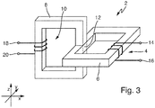
- Figure 3 shows the device 2 in a schematic three-dimensional view.
- the second magnetic circuit 8 is arranged at least in the area of the coupling section 12 essentially in a perpendicular plane of the first magnetic circuit 6 through the coupling section 12. This arrangement ensures that the magnetic field of the second magnetic circuit 8, in particular in the coupling region 12, is coupled essentially or mainly orthogonally to the alternating magnetic field in the first magnetic circuit 6.
- the first magnetic circuit 6 is aligned in an xy plane and the second magnetic circuit 8 is aligned in an xz plane.
- the arrangement according to the perpendicular plane includes, for example, any rotation or arrangement of the second magnetic circuit 8 in an xz plane.
- the arrangement of the second magnetic circuit 8 in the perpendicular plane of the first magnetic circuit 6 by the coupling section 12 includes any rotation of the FIG Figure 3 through the coupling area 12 and extending in the z-direction section of the second magnetic circuit 8 in the xz-plane.
- the other regions of the second magnetic circuit 8 that differ from the aforementioned section can, however, be oriented as desired, as long as the function of the second magnetic circuit 8 is maintained.
- one of the magnetic circuits 6 or 8 can also have an interruption, for example in the form of an air gap.
- one of the magnetic circuits 6 or 8 can also be equipped with a plunger core.
- multi-leg designs of the magnetic circuits 6 and 8 are also conceivable. It is therefore explicitly stated that the Figure 3 different designs are conceivable in order to carry out the methods explained in this description.
- Figure 4 shows in schematic form a further device 40 for compensating a ground fault.
- the device 40 comprises the one previously working according to the transducer principle Figures 1 to 3 explained device 2.
- the device 2 can be connected in parallel to further adjustable or non-adjustable inductances in order to provide a total inductance adapted to the case of an earth fault.
- a measuring element 42 is designed to determine a measured variable UNE which characterizes a potential earth fault and which represents a displacement voltage, the potential earth fault not yet having to be present when determining the measured variable UNE.
- the measured variable UNE is fed to a computing unit 44, which comprises a processor 46 and a memory element 48 connected to the processor 46.
- a computer program which is designed to carry out the method steps described here is stored on the memory element 48 to execute.
- measured variables determined such as the measured variable UNE, can be stored on the storage element 48.
- other or additional measured variables than the measured variable UNE can be evaluated in order to detect the potential earth fault.
- the phase currents and / or phase voltages of the field of the device 2 or other fields can be used to determine the potential earth fault.
- An operating parameter iSteuer (t) of the setting winding 10, which represents a potentially time-variant control current, is determined as a function of the at least one measured variable UNE by means of the arithmetic unit 44 in order to operate the compensation winding 4 at a ground fault operating point.
- other or additional measured variables can be evaluated than the measured variable UNE in order to determine the operating parameter iControl (t) by means of the arithmetic unit 44.
- the phase currents and / or phase voltages of the field of the device 2 or other fields can be used.
- the determination of the measured variable UNE and the determination of the operating parameter iSteuer (t) can be carried out both in a first and in a second operating mode, the first operating mode being characterized in that the medium or high voltage network 26 is in normal operation, with in normal operation there is no earth fault.
- the arithmetic unit 44 is designed to determine an earth fault in the medium or high voltage network 26, or the earth fault is determined in a further unit, not shown, and fed to the arithmetic unit 44. If the earth fault occurs now on, the device 40 changes to a second operating mode.
- the setting winding 10 is operated as a function of the at least one operating parameter iSteuer (t) in such a way that the compensation winding 4 is at the earth fault operating point.
- the operating parameter iControl (t) is fed to the current source 32, in particular to power electronics assigned to the current source 32.
- the operation of the compensation winding 4 in the earth fault operating point makes it possible to compensate for the capacitive current generated by an earth fault, for example, by the inductive current flowing in phase opposition by means of the compensation winding 4, and to minimize the harmonic currents.
- the ground fault operating point of the compensation winding 4 thus includes at least keeping the effective inductance constant in the event of a ground fault.
- the earth fault operating point can also include a variation over time of the inductance effective at the neutral point by means of the compensation winding 4. Consequently, the earth fault operating point is determined by the operating parameter iControl (t), which optionally includes an additional compensation signal for damping harmonics.
- Figure 5 shows a schematic flow diagram 50.
- the at least one measured variable UNE characterizing the potential earth fault is determined by means of the measuring element 42.
- the at least one operating parameter iSteuer (t) of the setting winding 10 is determined by means of the computing unit 44 as a function of the at least one measured variable UNE.
- the compensation signal is also determined, which, in addition to a starting point for the setting winding, provides a time-variant signal for compensating for harmonics.
- the case of an earth fault in the medium or high voltage network 26 is determined by means of the arithmetic unit 44.
- a step 58 when the earth fault is determined, the setting winding 10 is operated by means of the direct current source 32 as a function of the at least one operating parameter iSteuer (t), which includes the compensation signal, in such a way that the compensation winding 4 is in the earth fault operating point .
- variable currents can also be impressed on the setting winding with the direct current source 32. This is in part essential for the methods disclosed in this description. Reference is made here to the following explanations regarding the compensation signal.
- the direct current source 32 can also generate alternating currents, which is why it can generally also be referred to as a current source.
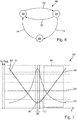
- Figure 6 shows a schematic state transition diagram 60.
- a third operating mode 66 is shown in the first operating mode 62.
- the medium or high voltage network 26 is in normal operation without a ground fault.
- the device 40 switches to the second operating mode 64 in order to compensate for the earth fault.
- an earth fault location is carried out, which is shown in FIG Figure 10 is explained in more detail. If the ground fault location can be carried out successfully in the third operating mode 66 and if, for example, the ground fault is successfully rectified due to the ground fault location, a change is made back to the first operating mode 62 in a rectification case 74.
- Figure 7 shows a schematic displacement voltage-residual current detuning diagram 80.
- a profile 82 of an amount of an earth fault residual current IR and a profile 84 of the measured variable UNE in the form of the displacement voltage are plotted against a detuning V.
- the detuning V relates to a ratio between the basic oscillation reactive current component of the residual earth fault current IR and the capacitive current effective at the earth fault point. For a value of V equal to zero, there is ideal compensation for the earth fault. For V less than zero, the medium or high voltage network 26 is overcompensated. For V greater than 0, the medium or high voltage network 26 is undercompensated.
- I. R. I. wr 2 + I. L. - I. CE 2 + ⁇ v I. v 2 + I. u
- An active residual current IWR results from the ohmic losses in the event of a single-pole earth fault.
- the coil current IL is the inductive earth fault current and the capacitive earth fault current is marked ICE.
- the harmonic components of the earth fault current are marked with Iv.
- the operating parameter iControl (t) is determined in the first operating mode 62 in such a way that the compensation winding 4 can be operated at an earth fault operating point 90.
- the earth fault operating point 90 can in particular be referred to as the ideal operating point, since the earth fault residual current IR is minimal here.
- the term IL-ICE is minimized or tends towards zero at the earth fault operating point 90.
- the compensation winding 4 is operated, for example, at a normal operating point 91, so that the setting winding is in the de-energized state.
- An example is an operating range 86 of a plunger core coil according to the prior art and taking into account a maximum residual earth fault current IR shown.
- the plunger core coil automatically adjusts itself to a corresponding inductance, which effects compensation in the event of a ground fault. If an earth fault occurs, the inductance of the plunger coil is not changed based on normal operation. In addition, the ground fault operating point 90 cannot be reached in the first operating mode 62 with the plunger core coil according to the prior art.
- the inductance of the compensation winding 4 is briefly changed and the displacement voltage is evaluated in terms of the measured variable UNE.
- Operating point 90 is determined as a function of the displacement voltage. Of course, other measured variables can also be used to determine the earth fault operating point 90.
- a first threshold 92 for the displacement voltage must not be exceeded permanently.
- a second threshold 94 also not being allowed to be exceeded briefly. This results in a range 96 of detuning V around V equal to zero, in which the high-voltage network 26 may not be operated even for a short time in its normal operation. This means, in particular for a plunger core coil, that it must not be operated at operating point 90 due to its essentially fixed or non-dynamically changeable inductance.
- the device 40 allows the high-voltage network 26 to be operated without current in the first operating mode 62 and then, in the event of an earth fault, to approach the previously determined earth fault operating point 90 by energizing the setting winding 10 and at operating point 90 by means of a time-variant operating parameter for the setting winding 10 To dampen harmonics.
- the approach to the ground fault operating point 90 can of course also be transferred to the case of a medium-voltage network 26.
- Figure 8 shows a schematic voltage-inductance-time diagram 100.
- the measured variable UNE is at a first level U1 according to a curve 102, to a second level at a point in time tV due to a change in the medium or high voltage network 26 Voltage level U2 to drop.
- a change in the medium-voltage or high-voltage network is therefore determined at the point in time tV in the first operating mode 62.
- a first inductance L1 is specified for the compensation winding 4 according to a curve 104 and the device 40 is operated accordingly.
- the setting winding 10 can also be de-energized. It goes without saying, however, that the setting winding 10 can also be supplied with current in order to achieve the inductance L1.
- a second inductance L2 is determined for the case of an earth fault 68 as a function of the measured variable UNE or as a function of a further measured variable. If the aforementioned change is determined at the point in time tV, a third inductance L3 for the event of an earth fault is determined in a period T2 following the first period T1. In the second time period T2, the compensation winding 4 dwells at the first inductance L1.
- the ground fault case 68 is determined at a point in time tES and the device 40 is operated in such a way that, in the second operating mode 64, the compensation winding 4 is set to the third inductance L3 according to the curve 104.
- the earth fault is therefore compensated for in a third time period T3.
- the change in the inductance L1 of the compensation winding 4 towards the inductance L3 is part of a change in the operating point at the point in time tES.
- the inductance L3 can be changed over time in the time period T3 in order to dampen harmonics, for example.
- Figure 9 shows in one embodiment the medium or high voltage network 26, the device 40 being represented schematically by means of the device 2, the computing unit 44 and the measuring element 42.
- Branches A, B and C are shown in which the respective currents I and voltages U are measured and made available to the arithmetic unit 44.
- the arithmetic unit 44 determines one or more harmonics of the earth fault current from the supplied variables, the harmonics according to FIG Equation 1 can be represented by the term ⁇ v I v 2 .
- the arithmetic unit 44 determines a compensation signal in phase opposition to the respective harmonic in the sense of a further operating parameter.
- a number of anti-phase compensation signals is determined according to the number of detected harmonics.
- a respective one of the anti-phase compensation signals comprises a corresponding frequency in the sense of a multiple of the network frequency, an amplitude and a phase.
- the anti-phase compensation signal is understood to be a signal which, introduced into the medium or high voltage network via the corresponding operation of the setting winding 10, has an anti-phase effect on the harmonic to be reduced.
- the frequencies and phases of the compensation signal and the harmonic to be reduced can differ.
- the anti-phase compensation signals are converted into a corresponding current signal and can thus be added to the operating parameter iControl (t) that has already been determined.
- the arithmetic unit 44 thus operates the setting winding 10 by means of the direct current source 32 as a function of the at least one operating parameter UNE and the compensation signal in such a way that the compensation winding 4 reduces an amplitude of the harmonic of the fault current at the earth fault operating point 90.
- the ground fault operating point 90 thus includes a setting of a time-variant inductance of the compensation winding 4, this inductance Includes frequency components with a multiple of the network frequency of the medium or high voltage network 26.
- the compensation winding 4 can also be determined as a function of the network variables Ua to Uc and / or Ia to Ic without taking the operating parameter UNE into account.
- the function 1 / L is selected in such a way that individual harmonics can be specifically generated in the sense of amplitude modulation. If, for example, a cosine-shaped curve is selected, a combination of individual frequency components according to equation 3 can be specifically generated according to the addition theorem.
- a modulation function according to equation 4 results, taking into account a stationary inductance L1, ie for a fundamental component.
- L. 1 L. 1 + A. 4th ⁇ cos 4th ⁇ t - ⁇ 4th
- the control current iControl (t) comprises a direct current component iDC and the compensation signal for operating the setting winding 10 and results from equation 5.
- the compensation signal is shown on the right-hand side of the direct current component iDC.
- Figure 10 shows in schematic form an earth fault location method which is carried out by means of the device 40.
- the operating parameter iControl (t) is varied in such a way that a pulse pattern 110 is formed in the medium or high voltage network 26. In Figure 7 this would correspond to a periodic deviation from the ideal earth fault operating point 90, at which the residual current IR is minimized, and a short-term setting of a pulse operating point 112.
- the setting winding 10 is controlled by means of a corresponding time-variant operating parameter iControl (t) operated in such a way that a periodic change takes place between the earth fault operating point 90 and the pulse operating point 112.
- a corresponding measuring point 114a, 114b and 114c is located at each of the branches 116a, 116b and 116c.
- branch 116c it is established at measuring point 114c that the sum of all phase currents is not constant due to the pronounced pulse pattern 110, whereby branch 116c includes the earth fault.
- the measuring point 114c is transmitted this deviation, for example, to the device 4 or a higher-level reporting point, with which fault location and reporting is carried out.
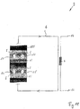
- FIG 11 shows a schematic view of the device 2 in an alternative embodiment.
- Second magnetic circuits 8 run within the first magnetic circuit 6 through respective coupling sections 12.
- the second magnetic circuits 8 are generated with the aid of setting windings 10 passed through a core material 110 of the first magnetic circuit 8 and cause a virtual, adjustable air gap in relation to the first magnetic one Circuit 6.
- the core material 110, together with the magnetic circuit 6, is part of the inductance 4, so there is only one iron core.
- the inductance of the compensation winding 4 can thus be adjusted by means of the setting winding 10 of a respective magnetic circuit.
Landscapes
- Physics & Mathematics (AREA)
- General Physics & Mathematics (AREA)
- Testing Of Short-Circuits, Discontinuities, Leakage, Or Incorrect Line Connections (AREA)
- Emergency Protection Circuit Devices (AREA)
Description
- Die Erfindung betrifft ein Verfahren zur Kompensation eines Erdschlusses in einem mehrphasigen Mittel- oder Hochspannungsnetz nach dem Oberbegriff des Anspruchs 1 sowie eine Vorrichtung zur Kompensation des Erdschlusses nach dem Oberbegriff eines nebengeordneten Anspruches.
- Es ist bekannt, dass insbesondere bei ausgedehnten Mittel- und Hochspannungsnetzen die Erdkapazität auf unerwünscht hohe Werte ansteigt, die bei einem Erdschluss im Netz zu einem hohen Erdschlussstrom führen. Um diesen Erdschlussstrom zu reduzieren wird in der Praxis eine Erdschlusslöschspule, auch Petersenspule genannt, an einen Sternpunkt des Netzes angeschlossen. Diese Erdschlusslöschspulen sind derart ausgestaltet, dass sie Erdschlussströme kompensieren.
- Bekannte Erdschlusslöschspulen sind als Tauchkernspulen ausgebildet. Durch ein Verstellen des Luftspaltes des Magnetkreises der Tauchkernspule mit Hilfe einer entsprechenden Verstellmechanik kann die Induktivität der Spule auf die Erdkapazität der zu schützenden Leitungsabschnitte des Netzes abgestimmt werden. Diese Abstimmung und Einstellung der Induktivität geschieht während des Normalbetriebs des Netzes ohne vorhandenen Erdschluss.
- Darüber hinaus ist aus der
DE 702 814 A eine regelbare Löschinduktivität für den induktiven Erdschlussschutz von Hochspannungsnetzen bekannt. Es ist ein den Eisenkern der Induktivität quermagnetisierender Magnetkreis vorgesehen, dessen magnetomotorische Kraft regelbar bzw. einstellbar ist. Die Stärke der Quermagnetisierung der jeweiligen Länge des geschützten Netzes ist derart angepasst, dass ein gewünschter Kompensationsgrad erreicht wird.
Aufgabe der Erfindung ist es daher, eine Vorrichtung zur Kompensation eines Erdschlusses derart weiterzubilden bzw. zu betreiben, dass sowohl ein Normalbetrieb als auch ein Erdschlussbetrieb des Netzes verbessert werden. -
WO 0215355 A1 - Die der Erfindung zu Grunde liegende Aufgabe wird durch ein Verfahren nach dem Anspruch 1 sowie durch eine Vorrichtung nach einem nebengeordneten Anspruch gelöst. Vorteilhafte Weiterbildungen sind in den Unteransprüchen angegeben. Für die Erfindung wichtige Merkmale finden sich ferner in der nachfolgenden Beschreibung und in den Zeichnungen, wobei die Merkmale sowohl in Alleinstellung als auch in unterschiedlichen Kombinationen für die Erfindung wichtig sein können, ohne dass hierauf nochmals explizit hingewiesen wird.
- Es wird ein Verfahren zum Betreiben einer Vorrichtung zur Kompensation eines Erdschlusses in einem mehrphasigen Mittel- oder Hochspannungsnetz vorschlagen, wobei die Vorrichtung eine Kompensationswicklung eines ersten magnetischen Kreises umfasst, und wobei mittels einer Einstellwicklung eines zweiten magnetischen Kreises eine Induktivität der Kompensationswicklung einstellbar ist.
- Zumindest eine einen potentiellen Erdschluss charakterisierende Messgröße wird ermittelt. Zumindest ein Betriebsparameter der Einstellwicklung wird in Abhängigkeit von der zumindest einen Messgröße ermittelt, wobei der zumindest eine Betriebsparameter derart ermittelt wird, um die Kompensationswicklung in einem Erdschluss-Betriebspunkt zu betreiben. Ein Erdschlussfall in dem Mittel- oder Hochspannungsnetz wird ermittelt. Wenn der Erdschlussfall ermittelt wird, wird die Einstellwicklung in Abhängigkeit von dem zumindest einen Betriebsparameter derart betrieben, so dass sich die Kompensationswicklung in dem Erdschluss-Betriebspunkt befindet.
- So kann auf hochdynamische Art und Weise der Reststrom an einer Erdschluss-Fehlerstelle durch Überlagerung mit dem durch den Erdschluss-Betriebspunkt bedingten Strom durch die Kompensationswicklung wesentlich reduziert werden. Insbesondere kann ausgehend von einem Normalbetrieb des Mittel- oder Hochspannungsnetzes in kürzester Zeit der Erdschluss-Betriebspunkt angefahren werden.
- Darüber hinaus findet eine Entkopplung des Erdschluss-Betriebspunktes in dem zweiten Betriebszustand von einem Betriebspunkt in dem ersten Betriebszustand statt. Diese Entkopplung ist insbesondere bei hohen Asymmetrien in Hochspannungsnetzen vorteilhaft, da dort im Normalbetrieb der Erdschluss-Betriebspunkt im Sinne eines idealen Betriebspunkts zu dauerhaft großen Verlagerungsspannungen führen würde und somit nicht einstellbar ist. Insbesondere muss keine Abwägung zwischen dem Normalbetrieb und dem Erdschluss-Betriebspunkt erfolgen, was die Wahl der jeweilig einzustellenden Induktivität betrifft.
- In einer vorteilhaften Ausführungsform wird der Betriebsparameter der Einstellwicklung während der ersten Betriebsart vor der Ermittlung des Erdschlussfalls ermittelt.
- In einer weiteren vorteilhaften Ausführungsform wird der Betriebsparameter der Einstellwicklung während der zweiten Betriebsart nach der Ermittlung des Erdschlussfalls (68) ermittelt. Selbstverständlich kann die Ermittlung des Betriebsparameters der Einstellwicklung sowohl vor als auch nach der Ermittlung des Erdschlussfalls erfolgen, was eine verbesserte Einstellung der Einstellwicklung ermöglicht.
- In einer vorteilhaften Ausführungsform wird in der zweiten Betriebsart eine Oberschwingung eines Erdschlussstromes ermittelt. Ein zu der Oberschwingung gegenphasiges Kompensationssignal im Sinne eines weiteren Betriebsparameters wird ermittelt. Die Einstellwicklung wird in Abhängigkeit von dem zumindest einen Betriebsparameter und dem Kompensationssignal derart betrieben, so dass die Kompensationswicklung in dem Erdschluss-Betriebspunkt eine Amplitude der Oberschwingung des Erdschlussstromes reduziert.
- Durch die Aufprägung des Kompensationssignals wird vorteilhaft erreicht, dass die Oberschwingungsströme im Erdschlussreststrom gedämpft werden und der Erdschlussreststrom minimiert wird. Selbstverständlich können auf diese Art und Weise auch weitere Oberschwingungen gedämpft werden, was zu einer weiteren Reduktion des Erdschlussstroms führt.
- In einer dritten Betriebsart wird gemäß einem Beispiel der Beschreibung die Einstellwicklung derart betrieben, dass ein periodischer Wechsel zwischen dem Erdschluss-Betriebspunkt und einem Puls-Betriebspunkt stattfindet. Dadurch wird vorteilhaft eine Pulsortung des Erdschlussfehlers ermöglicht. Gleichzeitig wird hierdurch die Schritt- und Berührspannung minimiert, da sich der Erdschluss-Betriebspunkt wie bei einer konventionellen Pulsation mittels zur Spule parallelen, schaltbaren Kapazitäten nicht im überkompensierten Bereich befinden muss.
- In einem Beispiel der Beschreibung wird an einem von der Vorrichtung entfernten, in einem Abzweig befindlichen Messpunkt zumindest eine weitere Messgröße ermittelt, wobei ein Erdschluss in dem Abzweig in Abhängigkeit von der weiteren Messgröße ermittelt wird. So kann durch den Messpunkt der Ort des Erdschlusses eingegrenzt werden.
- In einer vorteilhaften Weiterbildung des Verfahrens wird in der ersten Betriebsart eine Veränderung in dem Mittel- oder Hochspannungsnetz ermittelt. Der zumindest eine Betriebsparameter wird aktualisiert, wenn die Veränderung ermittelt wird. Es findet somit eine auf die Veränderung folgende unmittelbare Ermittlung des Betriebsparameters statt. Im Falle eines Erdschlusses ist die Vorrichtung damit stets an den veränderten Zustand des Mittel-oder Hochspannungsnetzes angepasst.
- In einer vorteilhaften Ausführungsform ist in der ersten Betriebsart die Einstellwicklung unbestromt. Hierdurch wird vorteilhaft Energie bei dem Betrieb der Vorrichtung eingespart. In der ersten Betriebsart müssen lediglich Messungen zur Ermittlung des Erdschluss-Betriebspunkts durchgeführt werden. Eine mechanische Verstellung wie bei der bekannten Petersenspule kann somit entfallen.
- Ein weiterer Aspekt der Erfindung betrifft die Vorrichtung zur Kompensation eines Erdschlusses in einem mehrphasigen Mittel- oder Hochspannungsnetz mit einer Kompensationswicklung eines ersten magnetischen Kreises, wobei mittels einer Einstellwicklung eines zweiten magnetischen Kreises eine Induktivität der Kompensationswicklung einstellbar ist. Die Vorrichtung umfasst:
- Mittel, um in einer ersten Betriebsart der Vorrichtung zumindest eine einen potentiellen Erdschluss charakterisierende Messgröße zu ermitteln,
- Mittel, um in der ersten Betriebsart zumindest einen Betriebsparameter der Einstellwicklung in Abhängigkeit von der zumindest einen Messgröße zu ermitteln, wobei der zumindest eine Betriebsparameter derart ermittelt wird, um die Kompensationswicklung in einem Erdschluss-Betriebspunkt zu betreiben,
- Mittel, um einen Erdschlussfall in dem Mittel- oder Hochspannungsnetz zu ermitteln, und
- Mittel, um, wenn der Erdschlussfall ermittelt wird, in einer zweiten Betriebsart der Vorrichtung die Einstellwicklung in Abhängigkeit von dem zumindest einen Betriebsparameter derart zu betreiben, so dass sich die Kompensationswicklung in dem Erdschluss-Betriebspunkt befindet. So können die Oberschwingungsströme im Erdschlussreststrom gedämpft werden.
- Weitere Merkmale, Anwendungsmöglichkeiten und Vorteile der Erfindung ergeben sich aus der nachfolgenden Beschreibung von Ausführungsbeispielen der Erfindung, die in den Figuren der Zeichnung dargestellt sind. Es werden für funktionsäquivalente Größen und Merkmale in allen Figuren auch bei unterschiedlichen Ausführungsformen die gleichen Bezugszeichen verwendet. In der Zeichnung zeigen:
- Figuren 1 und 4
- in schematischer Form eine Vorrichtung zur Kompensation eines Erdschlusses;
- Figuren 2 und 9
- ein ein schematisch dargestelltes Netzersatzschaltbild;
- Figur 3
- die Vorrichtung zur Kompensation des Erdschlusses in schematischer Form;
- Figur 5
- ein schematisches Ablaufdiagramm;
- Figur 6
- ein schematisches Zustands-Übergangs-Diagramm;
- Figur 7
- ein schematisches Verlagerungsspannung-Reststrom-Verstimmungs-Diagramm;
- Figur 8
- ein schematisches Spannungs-Induktivitäts-Zeit-Diagramm;
- Figur 10
- in schematischer Form ein Erdschluss-Ortungsverfahren; und
- Figur 11
- in schematischer Ansicht die Vorrichtung zur Kompensation eines Erdschlusses in einer alternativen Ausführungsform.
-
Figur 1 zeigt in schematischer Form eine Vorrichtung 2 zur Kompensation eines Erdschlusses in einem mehrphasigen Mittel- oder Hochspannungsnetz. Unter einem mehrphasigen Mittel- oder Hochspannungsnetz ist ein Wechselstromnetz der Mittel- oder Hochspannung zu verstehen. Die Vorrichtung 2 umfasst eine Kompensationswicklung 4 eines ersten magnetischen Kreises 6. Die Vorrichtung ist derart ausgebildet, dass mittels eines zweiten magnetischen Kreises 8 eine für das Wechselstromnetz wirksame Induktivität der Kompensationswicklung 4 einstellbar ist. Zur Einstellung der Induktivität der Kompensationswicklung 4 umfasst der zweite magnetische Kreis 8 eine Einstellwicklung 10, mittels derer eine wirksame Reluktanz des ersten magnetischen Kreises 6 einstellbar ist. Die Reluktanz wird auch als magnetischer Widerstand bezeichnet. Der erste magnetische Kreis 6 und der zweite magnetische Kreis 8 sind mittels eines ferromagnetischen Abschnitts 12 miteinander gekoppelt. Die Kompensationswicklung 4 hat zwei Anschlüsse 14 und 16. Die Einstellwicklung 10 hat Anschlüsse 18 und 20. - Die Kompensationswicklung 4 wird mit den Anschlüssen 14 und 16 zwischen einem Sternpunkt des Netzes und Erde angeordnet. Die Einstellwicklung 10 wird mit einer Stromquelle betrieben, wobei es sich bei der Stromquelle beispielsweise um eine dynamisch gesteuerte Gleichstromquelle oder um eine phasensynchrone Wechselstromquelle handeln kann, und wobei die Stromquelle einen Steuerstrom erzeugt. Die Stromquelle wird in
Figur 2 näher erläutert. Mithin bildet sich im Erdschlussfall in dem ersten magnetischen Kreis 6 ein magnetisches Wechselfeld 22 aus. Nach einem entsprechenden Einschwingvorgang bildet sich nach dem Einschalten der mit der Einstellwicklung 10 verbundenen Stromquelle in dem zweiten magnetischen Kreis 8 ein im Wesentlichen konstantes Magnetfeld 24 aus. Selbstverständlich kann die Einstellwicklung 10 auch derart betrieben werden, dass sich ein veränderliches magnetisches Feld 24 in den zweiten magnetischen Kreis ausbildet.
Der Koppelabschnitt 12 umfasst weisssche Bezirke, die magnetisierbare Bereiche eines ferromagnetischen Stoffes sind. Die weissschen Bezirke sind nun sowohl von dem Magnetfeld 22 als auch von dem Magnetfeld 24 beeinflussbar. Erhöht man den Steuerstrom durch die Einstellwicklung 10, werden durch das stärkere Magnetfeld 24 eine erhöhte Anzahl von weissschen Bezirken in dem ersten magnetischen Kreis 6, insbesondere in dem Koppelabschnitt 12, gemäß dem Verlauf des Magnetfelds 24 beeinflusst. Die gemäß dem Magnetfeld 24 beeinflussten weissschen Bezirke des ersten magnetischen Kreises 6 ändern dadurch entsprechend ihre Ausrichtung und das Verhalten gegenüber dem Wechselfeld 22. Mithin steigt durch eine Erhöhung des Steuerstroms durch die Einstellspule 10 die resultierende Reluktanz in dem ersten magnetischen Kreis 6. Eine Steigerung des magnetischen Widerstands bzw. der Reluktanz in dem ersten magnetischen Kreis 6 hat zur Folge, dass die mit der Kompensationswicklung 4 verbundene Induktivität sinkt. Entsprechendes gilt für ein Herabsetzen der Reluktanz. Somit ergibt sich die Einstellbarkeit der mit der Kompensationswicklung 4 gekoppelten Induktivität mittels der Einstellbarkeit des zweiten magnetischen Kreises 8. -
Figur 2 zeigt in schematischer Form, wie die Vorrichtung 2 zur Kompensation eines Erdschlusses in einem mehrphasigen Mittel- oder Hochspannungsnetz 26 anordenbar ist. Das gezeigte stark vereinfachte Ersatzschaltbild zeigt, wie die Vorrichtung 2 mit dem Anschluss 14 an einem Sternpunkt 28 eines Transformators 31, mit dem Anschluss 16 an Erde 30 und mit den Anschlüssen 18 und 20 an der Stromquelle 32 angeschlossen ist. Aus Übersichtsgründen sind nur die netzseitigen Wicklungen 34a, 34b und 34c des Transformators 31 gezeigt. Die netzseitigen Wicklungen 34 sind jeweiligen Phasen 36 zugeordnet. In Richtung des Pfeils 38 sind die Verbraucher des Netzes 26 angeordnet. Gemäß dem inFigur 2 gezeigten Ersatzschaltbild sind zwischen den einzelnen Phasen 36 und Erde 30 die Erdkapazitäten 38 dargestellt. Maßgebend für die Höhe eines Erdschlussstromes Ie ist der bestehende Parallelschwingkreis aus der Kompensationswicklung 4 und den Erdkapazitäten 38a und 38b der fehlerfreien Leiter. Die Fehlerstelle im gezeigten Ersatzschaltbild befindet sich somit zwischen der Phase 36c und Erde 30. - Das gezeigte Mittel- bzw. Hochspannungsnetz 26 stellt ein kompensiertes Netz dar, in dem beispielsweise Lichtbogen-Erdschlüsse selbstständig verlöschen. Mithin kann der Betrieb des Netzes 26 auch bei einem Dauer-Erdschluss aufrechterhalten werden. Bevorzugterweise wird das Netz überkompensiert betrieben, indem die Induktivität der Kompensationswicklung 4 kleiner gewählt wird als eine der Kapazität 30 entsprechende für den Parallelschwingkreis ideale Induktivität für die Kompensationswicklung 4. Mithin ist die Induktivität der Kompensationswicklung 4 mittels des zweiten magnetischen Kreises 8 derart einstellbar, so dass der Erdschlussstrom Ie mittels der Kompensationswicklung 4 im Wesentlichen kompensierbar ist.
-
Figur 3 zeigt in schematischer dreidimensionaler Ansicht die Vorrichtung 2. Der zweite magnetische Kreis 8 ist zumindest im Bereich des Koppelabschnitts 12 im Wesentlichen in einer Lotebene des ersten magnetischen Kreises 6 durch den Koppelabschnitt 12 angeordnet. Durch diese Anordnung wird sichergestellt, dass das Magnetfeld des zweiten magnetischen Kreises 8, insbesondere in dem Koppelbereich 12, im Wesentlichen bzw. hauptsächlich orthogonal zu dem magnetischen Wechselfeld in dem ersten magnetischen Kreis 6 eingekoppelt wird. Vorliegend ist der erste magnetische Kreis 6 in einer xy-Ebene ausgerichtet und der zweite magnetische Kreis 8 ist in einer xz-Ebene ausgerichtet. - In Bezug auf die
Figur 3 sollen im Folgenden weitere Ausführungsbeispiele der Anordnung des ersten und zweiten magnetischen Kreises 6, 8 zueinander erläutert werden. So können beispielsweise mehrere zweite magnetische Kreise 8 an dem ersten magnetischen Kreis 6 angeordnet werden. - Die Anordnung gemäß der Lotebene umfasst beispielsweise eine beliebige Drehung oder Anordnung des zweiten magnetischen Kreises 8 in einer xz-Ebene. Darüber hinaus umfasst die Anordnung des zweiten magnetischen Kreises 8 in der Lotebene des ersten magnetischen Kreises 6 durch den Koppelabschnitt 12 eine beliebige Drehung des in
Figur 3 durch den Koppelbereich 12 verlaufenden und in z-Richtung verlaufenden Abschnitts des zweiten magnetischen Kreises 8 in der xz-Ebene. Die übrigen von dem vorgenannten Abschnitt abweichenden Bereiche des zweiten magnetischen Kreises 8 können hingegen beliebig orientiert sein, soweit die Funktion des zweiten magnetischen Kreises 8 aufrechterhalten wird. - Selbstverständlich kann einer der magnetischen Kreise 6 oder 8 auch eine Unterbrechung, beispielsweise in Form eines Luftspalts, aufweisen. Selbstverständlich kann einer der magnetischen Kreise 6 oder 8 auch mit einem Tauchkern ausgestattet sein. Selbstverständlich sind auch mehrschenklige Ausführungen der magnetischen Kreise 6 und 8 denkbar. Mithin wird explizit darauf verwiesen, dass von der
Figur 3 abweichende Ausführungen denkbar sind, um die in dieser Beschreibung erläuterten Verfahren durchzuführen. -
Figur 4 zeigt in schematischer Form eine weitere Vorrichtung 40 zur Kompensation eines Erdschlusses. Die Vorrichtung 40 umfasst die nach dem Transduktor-Prinzip arbeitende zuvor zu denFiguren 1 bis 3 erläuterte Vorrichtung 2. Selbstverständlich kann die Vorrichtung 2 parallel zu weiteren verstellbaren oder nicht-verstellbaren Induktivitäten geschaltet werden, um eine auf den Erdschlussfall abgestimmte Gesamtinduktivität bereitzustellen. - Ein Messglied 42 ist dazu ausgebildet, eine einen potentiellen Erdschluss charakterisierende Messgröße UNE, welche eine Verlagerungsspannung darstellt, zu ermitteln, wobei der potentielle Erdschluss bei der Ermittlung der Messgröße UNE noch nicht vorliegen muss. Die Messgröße UNE wird einer Recheneinheit 44 zugeführt, welche einen Prozessor 46 und ein mit dem Prozessor 46 verbundenes Speicherelement 48 umfasst. Auf dem Speicherelement 48 ist ein Computerprogramm abgespeichert, welches dazu ausgebildet ist, die hier beschriebenen Verfahrensschritte auszuführen. Des Weiteren können auf dem Speicherelement 48 ermittelte Messgrößen wie beispielsweise die Messgröße UNE abgespeichert werden. Selbstverständlich können andere oder weitere Messgrößen als die Messgröße UNE ausgewertet werden, um den potentiellen Erdschluss zu detektieren. Beispielsweise können die Phasen-Ströme und/oder Phasen-Spannungen des Feldes der Vorrichtung 2 oder weiterer Felder zur Ermittlung des potentiellen Erdschlusses herangezogen werden.
- Ein Betriebsparameter iSteuer(t) der Einstellwicklung 10, welcher einen potentiell zeitvarianten Steuerstrom darstellt, wird in Abhängigkeit von der zumindest einen Messgröße UNE mittels der Recheneinheit 44 ermittelt, um die Kompensationswicklung 4 in einem Erdschluss-Betriebspunkt zu betreiben. Selbstverständlich können andere oder weitere Messgrößen als die Messgröße UNE ausgewertet werden, um den Betriebsparameter iSteuer(t) mittels Recheneinheit 44 zu ermitteln. Beispielsweise können die Phasen-Ströme und/oder Phasen-Spannungen des Feldes der Vorrichtung 2 oder weiterer Felder herangezogen werden. Die Ermittlung der Messgröße UNE und die Ermittlung des Betriebsparameters iSteuer(t) kann sowohl in einer ersten als auch in einer zweiten Betriebsart durchgeführt werden, wobei sich die erste Betriebsart dadurch gekennzeichnet, dass sich das Mittel- oder Hochspannungsnetz 26 in einem Normalbetrieb befindet, wobei in dem Normalbetrieb kein Erdschluss vorhanden ist.
Die Recheneinheit 44 ist dazu ausgebildet, einen Erdschlussfall in dem Mittel- oder Hochspannungsnetz 26 zu ermitteln oder aber es wird der Erdschlussfall in einer weiteren, nicht gezeigten Einheit ermittelt und der Recheneinheit 44 zugeführt. Tritt nun der Erdschlussfall ein, so wechselt die Vorrichtung 40 in eine zweite Betriebsart. - In der zweiten Betriebsart wird die Einstellwicklung 10 in Abhängigkeit von dem zumindest einen Betriebsparameter iSteuer(t) derart betrieben, sodass sich die Kompensationswicklung 4 in dem Erdschluss-Betriebspunkt befindet. Der Betriebsparameter iSteuer(t) wird der Stromquelle 32, insbesondere einer der Stromquelle 32 zugeordneten Leistungselektronik zugeführt. Der Betrieb der Kompensationswicklung 4 in dem Erdschluss-Betriebspunkt ermöglicht es, den durch einen Erdschluss erzeugten beispielsweise kapazitiven Strom durch den mittels der Kompensationswicklung 4 eingestellten gegenphasig fließenden beispielsweise induktiven Strom zu kompensieren und die Oberschwingungsströme zu minimieren.
- Der Erdschluss-Betriebspunkt der Kompensationswicklung 4 umfasst somit zumindest ein Konstanthalten der wirksamen Induktivität in dem Erdschlussfall. Darüber hinaus kann der Erdschluss-Betriebspunkt auch eine zeitliche Variation der mittels der Kompensationswicklung 4 am Sternpunkt wirksamen Induktivität umfassen. Folglich wird der Erdschluss-Betriebspunkt durch den Betriebsparameter iSteuer(t), welcher optional ein zusätzliches Kompensationssignal zur Dämpfung von Oberschwingungen umfasst, bestimmt.
-
Figur 5 zeigt ein schematisches Ablaufdiagramm 50. In dem Schritt 52 wird mittels des Messgliedes 42 die zumindest eine den potentiellen Erdschluss charakterisierende Messgröße UNE ermittelt. In einem Schritt 54 wird der zumindest eine Betriebsparameter iSteuer(t) der Einstellwicklung 10 in Abhängigkeit von der zumindest einen Messgröße UNE mittels der Recheneinheit 44 ermittelt. In dem Schritt 54 erfolgt auch die Ermittlung des Kompensationssignals, welches neben einem Aufpunkt für die Einstellwicklung ein zeitvariantes Signal zur Kompensation von Oberschwindungen bereitstellt. In einem Schritt 56 wird der Erdschlussfall in dem Mittel- oder Hochspannungsnetz 26 mittels der Recheneinheit 44 ermittelt. In einem Schritt 58 wird, wenn der Erdschlussfall ermittelt wird, mittels der Gleichstromquelle 32 die Einstellwicklung 10 in Abhängigkeit von dem zumindest einen Betriebsparameter iSteuer(t), welches das Kompensationssignal umfasst, derart betrieben, sodass sich die Kompensationswicklung 4 in dem Erdschluss-Betriebspunkt befindet. - Selbstverständlich lassen sich mit der Gleichstromquelle 32 auch veränderliche Ströme auf die Einstellwicklung einprägen. Dies ist für die in dieser Beschreibung offenbarten Verfahren teilweise unerlässlich. Es sei hierbei auf die nachfolgenden Ausführungen zu dem Kompensationssignal verwiesen. D. h. die Gleichstromquelle 32 kann auch Wechselströme erzeugen, weshalb sie allgemein auch als Stromquelle bezeichenbar ist.
-
Figur 6 zeigt ein schematisches Zustands-Übergangs-Diagramm 60. Neben der ersten Betriebsart 62 und der zweiten Betriebsart 64 ist eine dritte Betriebsart 66 gezeigt. In der ersten Betriebsart 62 befindet sich das Mittel- oder Hochspannungsnetz 26 in einem Normalbetrieb ohne Erdschluss. In dem Erdschlussfall 68 wechselt die Vorrichtung 40 in die zweite Betriebsart 64, um den Erdschluss zu kompensieren. - Wird beispielsweise unter Zuhilfenahme weiterer Messgrößen festgestellt, dass der Erdschluss selbstständig erloschen ist, was beispielsweise bei einem Blitzeinschlag im Bereich einer Freileitung vorkommt, so wird in diesem Selbstlöschungsfall 70 zurück in die erste Betriebsart 62 gewechselt. Wird in der zweiten Betriebsart 64 jedoch festgestellt, dass es zu keiner Selbstlöschung kommt, wird von einem permanenten Erdschluss, wie es beispielsweise bei einem Baggerangriff an eine Phase einer Erdleitung vorkommen kann, so wird ausgehend von der zweiten Betriebsart 64 in einem Permanenterdschlussfall 72 in die dritte Betriebsart 66 gewechselt.
- In der dritten Betriebsart 66 wird eine Erdschlussortung durchgeführt, was in
Figur 10 näher erläutert ist. Kann in der dritten Betriebsart 66 die Erdschlussortung erfolgreich durchgeführt werden und kommt es beispielsweise aufgrund der Erdschlussortung zu einer erfolgreichen Behebung des Erdschlusses, so wird in einem Behebungsfall 74 zurück in die erste Betriebsart 62 gewechselt. -
Figur 7 zeigt ein schematisches Verlagerungsspannung-Reststrom-Verstimmungs-Diagramm 80. Ein Verlauf 82 eines Betrags eines Erdschluss-Reststromes IR sowie ein Verlauf 84 der Messgröße UNE in Form der Verlagerungsspannung sind über einer Verstimmung V aufgetragen. Die Verstimmung V betrifft ein Verhältnis zwischen dem Grundschwingungs-Blindstromanteil des Erdschluss-Reststroms IR und dem an der Erdschlussstelle wirksamen kapazitiven Strom. Für einen Wert von V gleich Null liegt eine ideale Kompensation des Erdschlusses vor. Für V kleiner Null ist das Mittel- oder Hochspannungsnetz 26 überkompensiert. Für V größer 0 ist das Mittel- oder Hochspannungsnetz 26 unterkompensiert. Es ist inFigur 7 der Fall des Hochspannungsnetzes 26 gezeigt, der sich von dem Fall eines Mittelspannungsnetzes durch die hohe Verlagerungsspannung im Bereich der Verstimmung von Null unterscheidet. Davon abgesehen lässt sich der inFigur 7 erläuterte Betrieb ohne weiteres auch auf das Mittelspannungsnetz 26 übertragen. - Der Betrag des Erdschluss-Reststroms IR ergibt sich nach der nachfolgenden Gleichung 1:

- Ein Wirkreststrom IWR ergibt sich aus den ohmschen Verlusten bei einem einpoligen Erdschluss. Der Spulenstrom IL ist der induktive Erdschlussstrom und der kapazitive Erdschlussstrom ist mit ICE gekennzeichnet. Mit Iv sind die Oberschwingungsanteile des Erdschlussstromes gekennzeichnet. Des Weiteren ergibt sich im Erdschlussfall ein Unsymmetriestrom Iu.
- In Abhängigkeit von der den potentiellen Erdschluss charakterisierenden Messgröße UNE wird in der ersten Betriebsart 62 der Betriebsparameter iSteuer(t) derart ermittelt, dass die Kompensationswicklung 4 in einem Erdschluss-Betriebspunkt 90 betreibbar ist. Der Erdschluss-Betriebspunkt 90 ist insbesondere als idealer Betriebspunkt bezeichenbar, da hier der Erdschluss-Reststroms IR minimal wird. Insbesondere wird in dem Erdschluss-Betriebspunkt 90 der Term IL-ICE minimiert bzw. geht gegen Null. In der ersten Betriebsart 62 wird die Kompensationswicklung 4 beispielsweise in einem Normal-Betriebspunkt 91 betrieben, so dass sich die Einstellwicklung im stromlosen Zustand befindet.
- Beispielhaft ist ein Betriebsbereich 86 einer Tauchkernspule nach dem Stand der Technik und unter Berücksichtigung eines maximalen Erdschluss-Reststroms IR gezeigt. In diesem Betriebsbereich 86 stellt sich die Tauchkernspule selbstständig auf eine entsprechende Induktivität ein, welche im Fall des Erdschlusses eine Kompensation bewirkt. Tritt nun der Erdschlussfall ein, so wird die Induktivität der Tauchkernspule ausgehend von dem Normalbetrieb nicht verändert. Darüber hinaus lässt sich mit der Tauchkernspule nach dem Stand der Technik der Erdschluss-Betriebspunkt 90 in der ersten Betriebsart 62 nicht erreichen.
- In der ersten Betriebsart 62 der Vorrichtung 40, d.h. während des Normalbetriebs des Mittel- oder Hochspannungsnetzes 26, wird die Induktivität der Kompensationswicklung 4 kurzzeitig verändert und die Verlagerungsspannung im Sinne der Messgröße UNE ausgewertet. In Abhängigkeit von der Verlagerungsspannung wird der Betriebspunkt 90 ermittelt. Selbstverständlich können auch weitere Messgrößen zur Ermittlung des Erdschluss-Betriebspunkts 90 verwendet werden.
- In dem Hochspannungsnetz 26 ergibt sich aufgrund Asymmetrien im Netz bzw. aufgrund Beeinflussung anderer Energieversorgungsnetze, d.h. aufgrund unterschiedlicher Leiter-Erd-Kapazitäten und aufgrund von parallel geführten Leitungen, ein hohes Verlagerungsspannungs-Maximum. Deshalb darf eine erste Schwelle 92 für die Verlagerungsspannung nicht dauerhaft überschritten werden. Es ist jedoch möglich, die erste Schwelle 92 kurzzeitig zu Messzwecken zu überschreiten, wobei eine zweite Schwelle 94 auch kurzzeitig nicht überschritten werden darf. Damit ergibt sich ein Bereich 96 der Verstimmung V um V gleich Null herum, in welchem das Hochspannungsnetz 26 in seinem Normalbetrieb auch kurzzeitig nicht betrieben werden darf. Mithin ergibt sich insbesondere für eine Tauchkernspule, dass diese aufgrund ihrer im Wesentlichen festen bzw. nicht dynamisch veränderbaren Induktivität nicht in dem Betriebspunkt 90 betrieben werden darf.
- Die Vorrichtung 40 hingegen erlaubt es, das Hochspannungsnetz 26 in der ersten Betriebsart 62 unbestromt zu betreiben und anschließend in einem Erdschlussfall durch eine Bestromung der Einstellwicklung 10 den vorab ermittelten Erdschluss-Betriebspunkt 90 anzufahren und in dem Betriebspunkt 90 durch einen zeitvarianten Betriebsparameter für die Einstellwicklung 10 Oberschwingungen zu dämpfen . Selbstverständlich lässt sich das Anfahren des Erdschluss-Betriebspunktes 90 auch auf den Fall eines Mittelspannungsnetzes 26 übertragen.
-
Figur 8 zeigt ein schematisches Spannungs-Induktivitäts-Zeit-Diagramm 100. In einem ersten Zeitraum T1 befindet sich die Messgröße UNE gemäß einem Verlauf 102 auf einem ersten Niveau U1, um aufgrund einer Änderung in dem Mittel-oder Hochspannungsnetz 26 zu einem Zeitpunkt tV auf ein zweites Spannungsniveau U2 abzusinken. Mithin wird zu dem Zeitpunkt tV in der ersten Betriebsart 62 eine Veränderung in dem Mittel- oder Hochspannungsnetz ermittelt.
Während der ersten Betriebsart wird für die Kompensationswicklung 4 eine erste Induktivität L1 gemäß einem Verlauf 104 vorgegeben und die Vorrichtung 40 entsprechend betrieben. Zur Vorgabe der ersten Induktivität L1 kann die Einstellwicklung 10 auch unbestromt sein. Selbstverständlich ist aber auch eine Bestromung der Einstellwicklung 10 zum Erreichen der Induktivität L1 denkbar. - Des Weiteren wird während der ersten Betriebsart in dem ersten Zeitraum T1 eine zweite Induktivität L2 für den Erdschlussfall 68 in Abhängigkeit von der Messgröße UNE oder in Abhängigkeit von einer weiteren Messgröße ermittelt. Wenn die vorgenannte Veränderung zu dem Zeitpunkt tV festgestellt wird, wird in einem auf den ersten Zeitraum T1 folgenden Zeitraum T2 eine dritte Induktivität L3 für den Erdschlussfall ermittelt. Im zweiten Zeitraum T2 verweilt die Kompensationswicklung 4 bei der ersten Induktivität L1.
- Der Erdschlussfall 68 wird zu einem Zeitpunkt tES ermittelt und die Vorrichtung 40 wird derart betrieben, dass in der zweiten Betriebsart 64 die Kompensationswicklung 4 gemäß dem Verlauf 104 auf die dritte Induktivität L3 eingestellt wird. Mithin findet in einem dritten Zeitraum T3 eine Kompensation des Erdschlusses statt. Die Veränderung der Induktivität L1 der Kompensationswicklung 4 hin zu der Induktivität L3 ist Teil einer Veränderung des Betriebspunktes zu dem Zeitpunkt tES. Weitergehend kann die Induktivität L3 in dem Zeitraum T3 zeitlich verändert werden, um beispielsweise Oberschwingungen zu dämpfen.
-
Figur 9 zeigt in einer Ausführungsform das Mittel- oder Hochspannungsnetz 26, wobei die Vorrichtung 40 schematisch mittels der Vorrichtung 2, der Recheneinheit 44 und dem Messglied 42 repräsentiert wird. Es sind Abzweige A, B und C gezeigt, bei denen jeweilige Ströme I und Spannungen U gemessen und der Recheneinheit 44 zur Verfügung gestellt werden. Tritt nun der Erdschlussfall 68 in dem Abzweig A ein, so ermittelt die Recheneinheit 44 aus den zugeführten Größen eine oder mehrere Oberschwingungen des Erdfehlerstroms, wobei die Oberschwingungen gemäß der Gleichung 1 durch den Term ∑ vIv 2 repräsentiert werden. Die Recheneinheit 44 ermittelt ein zu der jeweiligen Oberschwingung gegenphasiges Kompensationssignal im Sinne eines weiteren Betriebsparameters. Entsprechend der Anzahl der detektierten Oberschwingungen wird eine Anzahl von gegenphasigen Kompensationssignalen ermittelt. Ein jeweiliges der gegenphasigen Kompensationssignale umfasst eine entsprechende Frequenz im Sinne eines Vielfachen der Netzfrequenz, eine Amplitude und eine Phase. Diese Parameter des jeweiligen Kompensationssignals werden von der Recheneinheit 44 mittels eines geeigneten Reglermodells ermittelt. - Unter dem gegenphasigen Kompensationssignal wird ein Signal verstanden, welches, über den entsprechenden Betrieb der Einstellwicklung 10 in das Mittel- oder Hochspannungsnetz eingebracht, eine gegenphasige Wirkung auf die zu reduzierende Oberschwingung hat. Folglich können sich Frequenzen und Phasen des Kompensationssignals und der zu reduzierenden Oberschwingung unterscheiden.
- Die gegenphasigen Kompensationssignale werden in ein entsprechendes Stromsignal gewandelt und können damit zu dem bereits ermittelten Betriebsparameter iSteuer(t) hinzuaddiert werden. Die Recheneinheit 44 betreibt damit die Einstellwicklung 10 mittels der Gleichstromquelle 32 in Abhängigkeit von dem zumindest einen Betriebsparameter UNE und dem Kompensationssignal derart, sodass die Kompensationswicklung 4 in dem Erdschluss-Betriebspunkt 90 eine Amplitude der Oberschwingung des Fehlerstroms reduziert. Der Erdschluss-Betriebspunkt 90 umfasst damit eine Einstellung einer zeitvarianten Induktivität der Kompensationswicklung 4, wobei diese Induktivität Frequenzanteile mit einem mehrfachen der Netzfrequenz des Mittel-oder Hochspannungsnetzes 26 umfasst. Selbstverständlich kann die Kompensationswicklung 4 auch in Abhängigkeit von den Netzgrößen Ua bis Uc und/oder Ia bis Ic ohne Berücksichtigung des Betriebsparameters UNE ermittelt werden.
- Durch eine den Betrieb der Einstellwicklung 10 mithilfe des Kompensationssignals werden Oberschwingungsströme im Erdschlussreststrom gedämpft.
- Wird eine sinusförmige Wechselspannung angesetzt, so ergibt sich der Spulenstrom beispielsweise nach Gleichung 2.

- Die Funktion 1/L wird so gewählt, dass sich einzelne Harmonische im Sinne der Amplitudenmodulation gezielt erzeugen lassen. Wählt man beispielsweise einen kosinusförmigen Verlauf, so lässt sich gemäß dem Additionstheorem eine Kombination einzelner Frequenzanteile nach Gleichung 3 gezielt erzeugen.

- Soll der Spulenstrom beispielsweise Anteile der dritten und fünften Harmonischen aufweisen, ergibt sich unter Berücksichtigung einer stationären Induktivität L1, d. h. für einen Grundschwingungsanteil, eine Modulationsfunktion nach Gleichung 4. Folglich werden mit einem Kompensationssignal mit einer ersten Frequenz Störschwingungen zweiter Frequenzen gedämpft.

- Der Steuerstrom iSteuer(t) umfasst einen Gleichstromanteil iDC sowie das Kompensationssignal zum Betrieb der Einstellwicklung 10 und ergibt sich nach Gleichung 5. Das Kompensationssignal ist rechterhand von dem Gleichstromanteil iDC gezeigt.

-
Figur 10 zeigt in schematischer Form ein Erdschluss-Ortungsverfahren, welches mittels der Vorrichtung 40 ausgeführt wird. Vorliegend wird der Betriebsparameter iSteuer(t) derart variiert, dass sich ein Pulsmuster 110 in dem Mittel- oder Hochspannungsnetz 26 ausbildet. InFigur 7 entspräche dies einem periodischen Abweichen von dem idealen Erdschluss-Betriebspunkt 90, in welchem der Reststrom IR minimiert wird, und einem kurzfristigen Einstellen eines Puls-Betriebspunkts 112. Damit wird in der dritten Betriebsart 66 die Einstellwicklung 10 mittels eines entsprechenden zeitvarianten Betriebsparameters iSteuer(t) derart betrieben, dass ein periodischer Wechsel zwischen dem Erdschluss-Betriebspunkt 90 und dem Puls-Betriebspunkt 112 stattfindet. - An jedem der Abzweige 116a, 116b und 116c befindet sich ein entsprechender Messpunkt 114a, 114b und 114c. In dem Abzweig 116c wird an dem Messpunkt 114c festgestellt, dass die Summe aller Phasenströme aufgrund des ausgeprägten Pulsmusters 110 nicht konstant ist, womit der Abzweig 116c den Erdschluss umfasst. Die Messstelle 114c übermittelt diese Abweichung beispielsweise an die Vorrichtung 4 oder eine übergeordnete Meldestelle, womit eine Fehlerortung und -meldung durchgeführt ist.
-
Figur 11 zeigt in schematischer Ansicht die Vorrichtung 2 in einer alternativen Ausführungsform. Zweite magnetische Kreise 8 verlaufen innerhalb des ersten magnetischen Kreises 6 durch jeweilige Koppelabschnitte 12. Die zweiten magnetischen Kreise 8 werden mithilfe von durch ein Kernmaterial 110 des ersten magnetischen Kreises 8 geführten Einstellwicklungen 10 erzeugt und bewirken einen virtuellen, einstellbaren Luftspalt in Bezug zu dem ersten magnetischen Kreis 6. Das Kernmaterial 110 ist mit dem Magnetkreis 6 Bestandteil der Induktivität 4, es gibt also nur einen Eisenkern. Damit ist mittels der Einstellwicklung 10 eines jeweiligen magnetischen Kreises die Induktivität der Kompensationswicklung 4 einstellbar.
Claims (12)
- Ein Verfahren zum Betreiben einer Vorrichtung (40) zur Kompensation eines Erdschlusses in einem mehrphasigen Mittel- oder Hochspannungsnetz (26) mit einer Kompensationswicklung (4) eines ersten magnetischen Kreises (8), wobei mittels einer Einstellwicklung (10) eines zweiten magnetischen Kreises (8) eine Induktivität der Kompensationswicklung (4) einstellbar ist, und wobei der erste magnetische Kreis (6) und der zweite magnetische Kreis (8) mittels eines ferromagnetischen Abschnitts (12) miteinander gekoppelt sind, wobei- zumindest eine einen potentiellen Erdschluss charakterisierende Messgröße (UNE) ermittelt wird,- zumindest ein Betriebsparameter (iSteuer(t)) der Einstellwicklung (10) in Abhängigkeit von der zumindest einen Messgröße (UNE) ermittelt wird, wobei der zumindest eine Betriebsparameter (iSteuer(t)) derart ermittelt wird, um die Kompensationswicklung (4) in einem Erdschluss-Betriebspunkt (90) zu betreiben, und- ein Erdschlussfall (68) in dem Mittel- oder Hochspannungsnetz (26) ermittelt wird, dadurch gekennzeichnet,- dass eine Oberschwingung eines Erdschlussstromes (Ie) ermittelt wird,- dass ein zu der Oberschwingung gegenphasiges Kompensationssignal ermittelt wird, und- dass die Einstellwicklung (10) in Abhängigkeit von dem zumindest einen Betriebsparameter (iSteuer(t)) und dem Kompensationssignal derart betrieben wird, so dass die Kompensationswicklung (4) in dem Erdschluss-Betriebspunkt (90) eine Amplitude der Oberschwingung des Erdschlussstromes (Ie) reduziert.
- Das Verfahren nach dem Anspruch 1,- wobei, wenn der Erdschlussfall (68) ermittelt wird, die Einstellwicklung (10) in Abhängigkeit von dem zumindest einen Betriebsparameter (iSteuer(t)) derart betrieben wird, so dass sich die Kompensationswicklung (4) in dem Erdschluss-Betriebspunkt (90) befindet.
- Das Verfahren nach dem Anspruch 2, wobei der Betriebsparameter (iSteuer(t)) der Einstellwicklung (10) während einer ersten Betriebsart (62) vor der Ermittlung des Erdschlussfalls (68) ermittelt wird.
- Das Verfahren nach dem Anspruch 2 oder 3, wobei der Betriebsparameter (iSteuer(t)) der Einstellwicklung (10) während der zweiten Betriebsart (64) nach der Ermittlung des Erdschlussfalls (68) ermittelt wird.
- Das Verfahren nach dem Anspruch 1,- wobei die Oberschwingung des Erdschlussstromes (Ie) während der ersten Betriebsart (62) ermittelt wird.
- Das Verfahren nach dem Anspruch 1,- wobei die Oberschwingung des Erdschlussstromes (Ie) während der zweiten Betriebsart (64) ermittelt wird.
- Das Verfahren nach einem der vorstehenden Ansprüche, wobei in der ersten Betriebsart (62) eine Veränderung in dem Mittel- oder Hochspannungsnetz (26) ermittelt wird, und wobei der zumindest eine Betriebsparameter (iSteuer(t)) aktualisiert wird, wenn die Veränderung ermittelt wird.
- Das Verfahren nach einem der vorstehenden Ansprüche,- wobei in der ersten Betriebsart (62) die Einstellwicklung (10) unbestromt ist.
- Das Verfahren nach einem der vorstehenden Ansprüche,- wobei, wenn der Erdschlussfall (68) ermittelt wird, die Einstellwicklung (10) in Abhängigkeit von dem zumindest einen Betriebsparameter (iSteuer(t)) derart betrieben wird, so dass der vorab ermittelte Erdschluss-Betriebspunkt (90) angefahren wird.
- Eine Vorrichtung (40) zur Kompensation eines Erdschlusses in einem mehrphasigen Mittel- oder Hochspannungsnetz (26) mit einer Kompensationswicklung (4) eines ersten magnetischen Kreises (8), wobei mittels einer Einstellwicklung (10) eines zweiten magnetischen Kreises (8) eine Induktivität der Kompensationswicklung (4) einstellbar ist, wobei der erste magnetische Kreis (6) und der zweite magnetische Kreis (8) mittels eines ferromagnetischen Abschnitts (12) miteinander gekoppelt sind, wobei die Vorrichtung weiterhin umfasst:- Mittel (42), um zumindest eine einen potentiellen Erdschluss charakterisierende Messgröße (UNE) zu ermitteln,- Mittel (44), um zumindest einen Betriebsparameter (iSteuer(t)) der Einstellwicklung (10) in Abhängigkeit von der zumindest einen Messgröße (UNE) zu ermitteln, wobei der zumindest eine Betriebsparameter (iSteuer(t)) derart ermittelt wird, um die Kompensationswicklung (4) in einem Erdschluss-Betriebspunkt (90) zu betreiben,- Mittel (44), um einen Erdschlussfall (68) in dem Mittel- oder Hochspannungsnetz (26) zu ermitteln, dadurch gekennzeichnet, dass die Vorrichtung weiterhin umfasst- Mittel, um eine Oberschwingung eines Erdschlussstromes (Ie) zu ermitteln,- Mittel, um ein zu der Oberschwingung gegenphasiges Kompensationssignal zu ermitteln, und- Mittel, um die Einstellwicklung (10) in Abhängigkeit von dem zumindest einen Betriebsparameter (iSteuer(t)) und dem Kompensationssignal derart zu betreiben, sodass die Kompensationswicklung (4) in dem Erdschluss-Betriebspunkt (90) eine Amplitude der Oberschwingung des Erdschlussstromes (Ie) reduziert.
- Die Vorrichtung (40) nach dem Anspruch 10 umfassend:- Mittel (44), um, wenn der Erdschlussfall (68) ermittelt wird, die Einstellwicklung (10) in Abhängigkeit von dem zumindest einen Betriebsparameter (iSteuer(t)) derart zu betreiben, so dass sich die Kompensationswicklung (4) in dem Erdschluss-Betriebspunkt (90) befindet.
- Die Vorrichtung (40) nach dem Anspruch 10 oder 11, welche dazu ausgebildet ist, das Verfahren nach einem der Ansprüche 2 bis 9 auszuführen.
Priority Applications (1)
| Application Number | Priority Date | Filing Date | Title |
|---|---|---|---|
| PL17174328T PL3287796T3 (pl) | 2016-06-06 | 2017-06-02 | Sposób i urządzenie do kompensacji zwarcia doziemnego |
Applications Claiming Priority (1)
| Application Number | Priority Date | Filing Date | Title |
|---|---|---|---|
| DE102016110420.5A DE102016110420A1 (de) | 2016-06-06 | 2016-06-06 | Verfahren und Vorrichtung zur Kompensation eines Erdschlusses |
Publications (3)
| Publication Number | Publication Date |
|---|---|
| EP3287796A2 EP3287796A2 (de) | 2018-02-28 |
| EP3287796A3 EP3287796A3 (de) | 2018-06-20 |
| EP3287796B1 true EP3287796B1 (de) | 2021-03-03 |
Family
ID=59030797
Family Applications (1)
| Application Number | Title | Priority Date | Filing Date |
|---|---|---|---|
| EP17174328.9A Active EP3287796B1 (de) | 2016-06-06 | 2017-06-02 | Verfahren und vorrichtung zur kompensation eines erdschlusses |
Country Status (3)
| Country | Link |
|---|---|
| EP (1) | EP3287796B1 (de) |
| DE (1) | DE102016110420A1 (de) |
| PL (1) | PL3287796T3 (de) |
Families Citing this family (3)
| Publication number | Priority date | Publication date | Assignee | Title |
|---|---|---|---|---|
| FI130596B (en) | 2019-02-04 | 2023-11-30 | Ensto Oy | Apparatus and procedure for using an electrical network |
| EP3907840A1 (de) * | 2020-05-08 | 2021-11-10 | Siemens Aktiengesellschaft | Verfahren und vorrichtung zur kompensation einer auf einem dreiphasigen spannungsversorgungsnetz auftretenden leitungsstörung |
| US11411389B1 (en) * | 2021-03-15 | 2022-08-09 | General Electric Technology Gmbh | Systems and methods for a controlled dynamic MHO distance characteristic |
Family Cites Families (11)
| Publication number | Priority date | Publication date | Assignee | Title |
|---|---|---|---|---|
| DE702814C (de) | 1938-08-02 | 1941-02-17 | Bbc Brown Boveri & Cie | Regelbare Loeschinduktivitaet fuer den induktiven |
| DE2711629C2 (de) * | 1977-03-17 | 1978-12-07 | Gossen Gmbh, 8520 Erlangen | Verfahren und Schaltungsanordnung zum Orten von Dauererdschlüssen in Drehstromnetzen |
| DE4413649C2 (de) * | 1994-04-20 | 1998-07-16 | Eberle A Gmbh | Meßverfahren und Schaltungsanordnung zur Ortung von Dauererdschlüssen |
| DE4429310C2 (de) * | 1994-08-18 | 1998-01-15 | Eberle A Gmbh | Verfahren und Vorrichtung zur Ortung von Erdschlüssen in Drehstromnetzen |
| DE19525417C2 (de) * | 1995-07-12 | 2000-03-23 | Starkstrom Geraetebau Gmbh | Anordnung zur Erdschluß-Stromkompensation eines mehrphasigen elektrischen Leitungsnetzes |
| AT411937B (de) * | 2000-08-11 | 2004-07-26 | Adaptive Regelsysteme Ges M B | Verfahren und vorrichtung zur erkennung und ortung von hochohmigen einpoligen erdfehlern |
| DE10146294C1 (de) * | 2001-09-19 | 2003-07-17 | Edc Gmbh | Abstimmung einer Erdschlusslöschspule auch während des Erdschlusses |
| DE10215025A1 (de) * | 2002-04-03 | 2003-10-16 | Kries Energietechnik Gmbh & Co | Verfahren und Vorrichtung zur Erkennung und/oder Ortung von Erdschlüssen und Kurzschlüssen in Drehstromnetzen |
| DE102007017543B4 (de) * | 2006-04-10 | 2012-12-13 | Technische Universität Graz | Verfahren zur Entfernungsortung von Erdschlüssen |
| AT509837B1 (de) * | 2010-02-25 | 2013-06-15 | Oebb Infrastruktur Ag | Vorrichtung zur fehlerstromreduktion |
| CZ308721B6 (cs) * | 2014-08-28 | 2021-03-24 | Ege, Spol.S R.O. | Způsob a zařízení pro automatické nastavení plynule a/nebo diskrétně laditelné zhášecí tlumivky v kompenzované síti elektrické soustavy |
-
2016
- 2016-06-06 DE DE102016110420.5A patent/DE102016110420A1/de not_active Withdrawn
-
2017
- 2017-06-02 PL PL17174328T patent/PL3287796T3/pl unknown
- 2017-06-02 EP EP17174328.9A patent/EP3287796B1/de active Active
Non-Patent Citations (1)
| Title |
|---|
| None * |
Also Published As
| Publication number | Publication date |
|---|---|
| DE102016110420A1 (de) | 2017-12-07 |
| EP3287796A3 (de) | 2018-06-20 |
| PL3287796T3 (pl) | 2021-09-13 |
| EP3287796A2 (de) | 2018-02-28 |
Similar Documents
| Publication | Publication Date | Title |
|---|---|---|
| EP2622615B1 (de) | Anordnung und verfahren zur kompensation eines magnetischen gleichflusses in einem transformatorkern | |
| DE69332697T2 (de) | Verfahren und Vorrichtung zur Feststellung eines Erdschlusswiderstandes in einem Elektrofahrzeug | |
| DE19930412C1 (de) | Aktiv abgeschirmte supraleitende Magnetanordnung mit Feldstörungskompensation | |
| DE102007049667B4 (de) | Anordnung und Verfahren zur Kompensation eines Fehlerstromes bei einem Erdschluss | |
| EP3663783B1 (de) | Magnetfeld-messvorrichtung und verfahren zur erfassung eines lokalisierungsstroms in einem verzweigten wechselstrom-stromversorgungssystem | |
| DE3208133A1 (de) | Elektromagnetisches lager mit redundanzeigenschaften | |
| EP1065513B1 (de) | Aktiv abgeschirmte supraleitende Magnetanordnung mit Feldstörungskompensation | |
| DE19532149A1 (de) | Verfahren und Vorrichtung zur Korrektur einer Flußrichtung eines Modellflusses einer geberlosen, feldorientiert betriebenen Drehfeldmaschine bis zur Frequenz Null | |
| EP3287796B1 (de) | Verfahren und vorrichtung zur kompensation eines erdschlusses | |
| DE112015003484B4 (de) | Energie-Umwandlungsvorrichtung | |
| EP1182463B1 (de) | Dimensionierung zusätzlicher Strompfade zur Optimierung des Störverhaltens einer supraleitenden Magnetanordnung | |
| DE10241966A1 (de) | Supraleitende Magnetanordnung und Verfahren | |
| DE69329326T2 (de) | Verfahren und Vorrichtung zum Messen der Anpassung und Fehlanpassung der Kompensation eines Stromversorgungsnetzes | |
| EP4409311B1 (de) | Indirektes kalibrierverfahren für ein elektromagnetisches induktionsverfahren und messanordnung zur durchführung des verfahrens | |
| DE2731453C3 (de) | Erdschlußdetektor | |
| EP2362514B1 (de) | Vorrichtung zur Fehlerstromreduktion | |
| DE102008037831B4 (de) | Verfahren zum Betreiben eines Fehlerstromschutzschalters sowie Fehlerstromschutzschalter | |
| EP1182462B1 (de) | Dimensionierung einer Magnetanordnung mit einem zusätzlichen stromführenden Spulensystem | |
| DE2103340B2 (de) | Verfahren und Vorrichtung zur Fein stabilisierung der magnetischen Feld starke eines Kernresonanzspektrometers | |
| DE69114479T2 (de) | Lagedetektor. | |
| EP2169797B1 (de) | Verfahren und messvorrichtung zur messung eines ausgangsstroms einer getakteten halbbrueckenschaltung | |
| AT524958B1 (de) | Verfahren zur Ermittlung von Netzparametern zur Regelung einer Petersen-Spule | |
| DE1463139A1 (de) | Anzeigevorrichtung fuer einen Belastungszustand eines Stromkreises | |
| DE968624C (de) | Schutzeinrichtung in Mehrphasennetzen mit Kurzschlussfortschaltung | |
| EP2428773B1 (de) | Phasenanaloger Wegsensor |
Legal Events
| Date | Code | Title | Description |
|---|---|---|---|
| PUAI | Public reference made under article 153(3) epc to a published international application that has entered the european phase |
Free format text: ORIGINAL CODE: 0009012 |
|
| STAA | Information on the status of an ep patent application or granted ep patent |
Free format text: STATUS: THE APPLICATION HAS BEEN PUBLISHED |
|
| AK | Designated contracting states |
Kind code of ref document: A2 Designated state(s): AL AT BE BG CH CY CZ DE DK EE ES FI FR GB GR HR HU IE IS IT LI LT LU LV MC MK MT NL NO PL PT RO RS SE SI SK SM TR |
|
| AX | Request for extension of the european patent |
Extension state: BA ME |
|
| PUAL | Search report despatched |
Free format text: ORIGINAL CODE: 0009013 |
|
| AK | Designated contracting states |
Kind code of ref document: A3 Designated state(s): AL AT BE BG CH CY CZ DE DK EE ES FI FR GB GR HR HU IE IS IT LI LT LU LV MC MK MT NL NO PL PT RO RS SE SI SK SM TR |
|
| AX | Request for extension of the european patent |
Extension state: BA ME |
|
| RIC1 | Information provided on ipc code assigned before grant |
Ipc: G01R 31/11 20060101ALI20180516BHEP Ipc: H01F 29/14 20060101ALI20180516BHEP Ipc: H02H 7/26 20060101ALI20180516BHEP Ipc: G01R 31/08 20060101ALI20180516BHEP Ipc: G01R 31/02 20060101AFI20180516BHEP Ipc: H02H 9/08 20060101ALI20180516BHEP |
|
| STAA | Information on the status of an ep patent application or granted ep patent |
Free format text: STATUS: REQUEST FOR EXAMINATION WAS MADE |
|
| 17P | Request for examination filed |
Effective date: 20181022 |
|
| RBV | Designated contracting states (corrected) |
Designated state(s): AL AT BE BG CH CY CZ DE DK EE ES FI FR GB GR HR HU IE IS IT LI LT LU LV MC MK MT NL NO PL PT RO RS SE SI SK SM TR |
|
| STAA | Information on the status of an ep patent application or granted ep patent |
Free format text: STATUS: EXAMINATION IS IN PROGRESS |
|
| 17Q | First examination report despatched |
Effective date: 20200416 |
|
| REG | Reference to a national code |
Ref country code: DE Ref legal event code: R079 Ref document number: 502017009541 Country of ref document: DE Free format text: PREVIOUS MAIN CLASS: G01R0031020000 Ipc: G01R0031520000 |
|
| GRAP | Despatch of communication of intention to grant a patent |
Free format text: ORIGINAL CODE: EPIDOSNIGR1 |
|
| STAA | Information on the status of an ep patent application or granted ep patent |
Free format text: STATUS: GRANT OF PATENT IS INTENDED |
|
| RIC1 | Information provided on ipc code assigned before grant |
Ipc: H02H 7/26 20060101ALI20201019BHEP Ipc: H02H 9/08 20060101ALI20201019BHEP Ipc: G01R 31/08 20200101ALI20201019BHEP Ipc: H01F 29/14 20060101ALI20201019BHEP Ipc: G01R 31/52 20200101AFI20201019BHEP Ipc: G01R 31/11 20060101ALI20201019BHEP |
|
| INTG | Intention to grant announced |
Effective date: 20201103 |
|
| GRAS | Grant fee paid |
Free format text: ORIGINAL CODE: EPIDOSNIGR3 |
|
| GRAA | (expected) grant |
Free format text: ORIGINAL CODE: 0009210 |
|
| STAA | Information on the status of an ep patent application or granted ep patent |
Free format text: STATUS: THE PATENT HAS BEEN GRANTED |
|
| AK | Designated contracting states |
Kind code of ref document: B1 Designated state(s): AL AT BE BG CH CY CZ DE DK EE ES FI FR GB GR HR HU IE IS IT LI LT LU LV MC MK MT NL NO PL PT RO RS SE SI SK SM TR |
|
| REG | Reference to a national code |
Ref country code: GB Ref legal event code: FG4D Free format text: NOT ENGLISH |
|
| REG | Reference to a national code |
Ref country code: AT Ref legal event code: REF Ref document number: 1367793 Country of ref document: AT Kind code of ref document: T Effective date: 20210315 Ref country code: CH Ref legal event code: EP |
|
| REG | Reference to a national code |
Ref country code: DE Ref legal event code: R096 Ref document number: 502017009541 Country of ref document: DE |
|
| REG | Reference to a national code |
Ref country code: CH Ref legal event code: NV Representative=s name: DREISS PATENTANWAELTE PARTG MBB, DE Ref country code: IE Ref legal event code: FG4D Free format text: LANGUAGE OF EP DOCUMENT: GERMAN |
|
| REG | Reference to a national code |
Ref country code: LT Ref legal event code: MG9D |
|
| PG25 | Lapsed in a contracting state [announced via postgrant information from national office to epo] |
Ref country code: FI Free format text: LAPSE BECAUSE OF FAILURE TO SUBMIT A TRANSLATION OF THE DESCRIPTION OR TO PAY THE FEE WITHIN THE PRESCRIBED TIME-LIMIT Effective date: 20210303 Ref country code: HR Free format text: LAPSE BECAUSE OF FAILURE TO SUBMIT A TRANSLATION OF THE DESCRIPTION OR TO PAY THE FEE WITHIN THE PRESCRIBED TIME-LIMIT Effective date: 20210303 Ref country code: GR Free format text: LAPSE BECAUSE OF FAILURE TO SUBMIT A TRANSLATION OF THE DESCRIPTION OR TO PAY THE FEE WITHIN THE PRESCRIBED TIME-LIMIT Effective date: 20210604 Ref country code: NO Free format text: LAPSE BECAUSE OF FAILURE TO SUBMIT A TRANSLATION OF THE DESCRIPTION OR TO PAY THE FEE WITHIN THE PRESCRIBED TIME-LIMIT Effective date: 20210603 Ref country code: BG Free format text: LAPSE BECAUSE OF FAILURE TO SUBMIT A TRANSLATION OF THE DESCRIPTION OR TO PAY THE FEE WITHIN THE PRESCRIBED TIME-LIMIT Effective date: 20210603 Ref country code: LT Free format text: LAPSE BECAUSE OF FAILURE TO SUBMIT A TRANSLATION OF THE DESCRIPTION OR TO PAY THE FEE WITHIN THE PRESCRIBED TIME-LIMIT Effective date: 20210303 |
|
| REG | Reference to a national code |
Ref country code: NL Ref legal event code: MP Effective date: 20210303 |
|
| PG25 | Lapsed in a contracting state [announced via postgrant information from national office to epo] |
Ref country code: LV Free format text: LAPSE BECAUSE OF FAILURE TO SUBMIT A TRANSLATION OF THE DESCRIPTION OR TO PAY THE FEE WITHIN THE PRESCRIBED TIME-LIMIT Effective date: 20210303 Ref country code: RS Free format text: LAPSE BECAUSE OF FAILURE TO SUBMIT A TRANSLATION OF THE DESCRIPTION OR TO PAY THE FEE WITHIN THE PRESCRIBED TIME-LIMIT Effective date: 20210303 Ref country code: SE Free format text: LAPSE BECAUSE OF FAILURE TO SUBMIT A TRANSLATION OF THE DESCRIPTION OR TO PAY THE FEE WITHIN THE PRESCRIBED TIME-LIMIT Effective date: 20210303 |
|
| PG25 | Lapsed in a contracting state [announced via postgrant information from national office to epo] |
Ref country code: NL Free format text: LAPSE BECAUSE OF FAILURE TO SUBMIT A TRANSLATION OF THE DESCRIPTION OR TO PAY THE FEE WITHIN THE PRESCRIBED TIME-LIMIT Effective date: 20210303 |
|
| PG25 | Lapsed in a contracting state [announced via postgrant information from national office to epo] |
Ref country code: SM Free format text: LAPSE BECAUSE OF FAILURE TO SUBMIT A TRANSLATION OF THE DESCRIPTION OR TO PAY THE FEE WITHIN THE PRESCRIBED TIME-LIMIT Effective date: 20210303 Ref country code: EE Free format text: LAPSE BECAUSE OF FAILURE TO SUBMIT A TRANSLATION OF THE DESCRIPTION OR TO PAY THE FEE WITHIN THE PRESCRIBED TIME-LIMIT Effective date: 20210303 |
|
| PG25 | Lapsed in a contracting state [announced via postgrant information from national office to epo] |
Ref country code: PT Free format text: LAPSE BECAUSE OF FAILURE TO SUBMIT A TRANSLATION OF THE DESCRIPTION OR TO PAY THE FEE WITHIN THE PRESCRIBED TIME-LIMIT Effective date: 20210705 Ref country code: RO Free format text: LAPSE BECAUSE OF FAILURE TO SUBMIT A TRANSLATION OF THE DESCRIPTION OR TO PAY THE FEE WITHIN THE PRESCRIBED TIME-LIMIT Effective date: 20210303 Ref country code: SK Free format text: LAPSE BECAUSE OF FAILURE TO SUBMIT A TRANSLATION OF THE DESCRIPTION OR TO PAY THE FEE WITHIN THE PRESCRIBED TIME-LIMIT Effective date: 20210303 Ref country code: IS Free format text: LAPSE BECAUSE OF FAILURE TO SUBMIT A TRANSLATION OF THE DESCRIPTION OR TO PAY THE FEE WITHIN THE PRESCRIBED TIME-LIMIT Effective date: 20210703 |
|
| REG | Reference to a national code |
Ref country code: DE Ref legal event code: R097 Ref document number: 502017009541 Country of ref document: DE |
|
| PLBE | No opposition filed within time limit |
Free format text: ORIGINAL CODE: 0009261 |
|
| STAA | Information on the status of an ep patent application or granted ep patent |
Free format text: STATUS: NO OPPOSITION FILED WITHIN TIME LIMIT |
|
| PG25 | Lapsed in a contracting state [announced via postgrant information from national office to epo] |
Ref country code: MC Free format text: LAPSE BECAUSE OF FAILURE TO SUBMIT A TRANSLATION OF THE DESCRIPTION OR TO PAY THE FEE WITHIN THE PRESCRIBED TIME-LIMIT Effective date: 20210303 Ref country code: DK Free format text: LAPSE BECAUSE OF FAILURE TO SUBMIT A TRANSLATION OF THE DESCRIPTION OR TO PAY THE FEE WITHIN THE PRESCRIBED TIME-LIMIT Effective date: 20210303 Ref country code: AL Free format text: LAPSE BECAUSE OF FAILURE TO SUBMIT A TRANSLATION OF THE DESCRIPTION OR TO PAY THE FEE WITHIN THE PRESCRIBED TIME-LIMIT Effective date: 20210303 Ref country code: ES Free format text: LAPSE BECAUSE OF FAILURE TO SUBMIT A TRANSLATION OF THE DESCRIPTION OR TO PAY THE FEE WITHIN THE PRESCRIBED TIME-LIMIT Effective date: 20210303 |
|
| 26N | No opposition filed |
Effective date: 20211206 |
|
| GBPC | Gb: european patent ceased through non-payment of renewal fee |
Effective date: 20210603 |
|
| PG25 | Lapsed in a contracting state [announced via postgrant information from national office to epo] |
Ref country code: SI Free format text: LAPSE BECAUSE OF FAILURE TO SUBMIT A TRANSLATION OF THE DESCRIPTION OR TO PAY THE FEE WITHIN THE PRESCRIBED TIME-LIMIT Effective date: 20210303 |
|
| REG | Reference to a national code |
Ref country code: BE Ref legal event code: MM Effective date: 20210630 |
|
| PG25 | Lapsed in a contracting state [announced via postgrant information from national office to epo] |
Ref country code: LU Free format text: LAPSE BECAUSE OF NON-PAYMENT OF DUE FEES Effective date: 20210602 |
|
| PG25 | Lapsed in a contracting state [announced via postgrant information from national office to epo] |
Ref country code: IT Free format text: LAPSE BECAUSE OF FAILURE TO SUBMIT A TRANSLATION OF THE DESCRIPTION OR TO PAY THE FEE WITHIN THE PRESCRIBED TIME-LIMIT Effective date: 20210303 Ref country code: IE Free format text: LAPSE BECAUSE OF NON-PAYMENT OF DUE FEES Effective date: 20210602 Ref country code: GB Free format text: LAPSE BECAUSE OF NON-PAYMENT OF DUE FEES Effective date: 20210603 |
|
| PG25 | Lapsed in a contracting state [announced via postgrant information from national office to epo] |
Ref country code: IS Free format text: LAPSE BECAUSE OF FAILURE TO SUBMIT A TRANSLATION OF THE DESCRIPTION OR TO PAY THE FEE WITHIN THE PRESCRIBED TIME-LIMIT Effective date: 20210703 Ref country code: FR Free format text: LAPSE BECAUSE OF NON-PAYMENT OF DUE FEES Effective date: 20210630 |
|
| PG25 | Lapsed in a contracting state [announced via postgrant information from national office to epo] |
Ref country code: BE Free format text: LAPSE BECAUSE OF NON-PAYMENT OF DUE FEES Effective date: 20210630 |
|
| PG25 | Lapsed in a contracting state [announced via postgrant information from national office to epo] |
Ref country code: HU Free format text: LAPSE BECAUSE OF FAILURE TO SUBMIT A TRANSLATION OF THE DESCRIPTION OR TO PAY THE FEE WITHIN THE PRESCRIBED TIME-LIMIT; INVALID AB INITIO Effective date: 20170602 |
|
| PG25 | Lapsed in a contracting state [announced via postgrant information from national office to epo] |
Ref country code: CY Free format text: LAPSE BECAUSE OF FAILURE TO SUBMIT A TRANSLATION OF THE DESCRIPTION OR TO PAY THE FEE WITHIN THE PRESCRIBED TIME-LIMIT Effective date: 20210303 |
|
| P01 | Opt-out of the competence of the unified patent court (upc) registered |
Effective date: 20230809 |
|
| PG25 | Lapsed in a contracting state [announced via postgrant information from national office to epo] |
Ref country code: MK Free format text: LAPSE BECAUSE OF FAILURE TO SUBMIT A TRANSLATION OF THE DESCRIPTION OR TO PAY THE FEE WITHIN THE PRESCRIBED TIME-LIMIT Effective date: 20210303 |
|
| PG25 | Lapsed in a contracting state [announced via postgrant information from national office to epo] |
Ref country code: TR Free format text: LAPSE BECAUSE OF FAILURE TO SUBMIT A TRANSLATION OF THE DESCRIPTION OR TO PAY THE FEE WITHIN THE PRESCRIBED TIME-LIMIT Effective date: 20210303 |
|
| PG25 | Lapsed in a contracting state [announced via postgrant information from national office to epo] |
Ref country code: MT Free format text: LAPSE BECAUSE OF FAILURE TO SUBMIT A TRANSLATION OF THE DESCRIPTION OR TO PAY THE FEE WITHIN THE PRESCRIBED TIME-LIMIT Effective date: 20210303 |
|
| PGFP | Annual fee paid to national office [announced via postgrant information from national office to epo] |
Ref country code: PL Payment date: 20250522 Year of fee payment: 9 |
|
| PGFP | Annual fee paid to national office [announced via postgrant information from national office to epo] |
Ref country code: AT Payment date: 20250623 Year of fee payment: 9 |
|
| PGFP | Annual fee paid to national office [announced via postgrant information from national office to epo] |
Ref country code: CZ Payment date: 20250527 Year of fee payment: 9 |
|
| PGFP | Annual fee paid to national office [announced via postgrant information from national office to epo] |
Ref country code: DE Payment date: 20250815 Year of fee payment: 9 |
|
| PGFP | Annual fee paid to national office [announced via postgrant information from national office to epo] |
Ref country code: CH Payment date: 20250701 Year of fee payment: 9 |