EP3288046A1 - Spulenvorrichtung - Google Patents
Spulenvorrichtung Download PDFInfo
- Publication number
- EP3288046A1 EP3288046A1 EP16185586.1A EP16185586A EP3288046A1 EP 3288046 A1 EP3288046 A1 EP 3288046A1 EP 16185586 A EP16185586 A EP 16185586A EP 3288046 A1 EP3288046 A1 EP 3288046A1
- Authority
- EP
- European Patent Office
- Prior art keywords
- coil
- coil device
- cooling plate
- cooling
- windings
- Prior art date
- Legal status (The legal status is an assumption and is not a legal conclusion. Google has not performed a legal analysis and makes no representation as to the accuracy of the status listed.)
- Granted
Links
Images


Classifications
-
- H—ELECTRICITY
- H01—ELECTRIC ELEMENTS
- H01F—MAGNETS; INDUCTANCES; TRANSFORMERS; SELECTION OF MATERIALS FOR THEIR MAGNETIC PROPERTIES
- H01F27/00—Details of transformers or inductances, in general
- H01F27/08—Cooling; Ventilating
- H01F27/10—Liquid cooling
-
- H—ELECTRICITY
- H01—ELECTRIC ELEMENTS
- H01F—MAGNETS; INDUCTANCES; TRANSFORMERS; SELECTION OF MATERIALS FOR THEIR MAGNETIC PROPERTIES
- H01F27/00—Details of transformers or inductances, in general
- H01F27/28—Coils; Windings; Conductive connections
- H01F27/2876—Cooling
-
- H—ELECTRICITY
- H01—ELECTRIC ELEMENTS
- H01F—MAGNETS; INDUCTANCES; TRANSFORMERS; SELECTION OF MATERIALS FOR THEIR MAGNETIC PROPERTIES
- H01F27/00—Details of transformers or inductances, in general
- H01F27/28—Coils; Windings; Conductive connections
- H01F27/32—Insulating of coils, windings, or parts thereof
-
- H—ELECTRICITY
- H01—ELECTRIC ELEMENTS
- H01F—MAGNETS; INDUCTANCES; TRANSFORMERS; SELECTION OF MATERIALS FOR THEIR MAGNETIC PROPERTIES
- H01F37/00—Fixed inductances not covered by group H01F17/00
Definitions
- the invention relates to a coil device according to the preamble of claim 1.
- a plurality of coil devices such as choke coils, which are wound from several layers of an insulated conductor known. Due to the electrical stress of a coil device occur thermal losses, for example, within the windings of the coil device or in its coil core, which is formed for example of iron on. Typically, the individual windings of the coil device are electrically isolated from each other by the introduction of an insulating material. Here, a sufficiently good heat dissipation of the coil device is ensured. A preferred cooling or cooling of the coil device or its winding layers is dimensioned contact, so that the predetermined space can be optimally utilized.
- a cooling plate is introduced into the coil device, which in particular must be electrically insulated from a yoke of a winding of the coil device.
- a cooling plate in particular a metallic cooling plate, within the coil device has the disadvantage that due to the magnetic fields occurring electrical currents are induced in this, leading to losses (ohmic losses due to eddy currents).
- Waveguides are known from the prior art, which are used for the windings of the coil device. By the waveguides can be passed a coolant, which warms the coil device.
- Plastic cooling bags are known with a Y-structure, which can be introduced into the coil device or one of its windings. In order to increase the thermal conductivity between the windings of the coil device and said Y-structure, these are at least partially embedded in a resin, so that air pockets can be reduced or at best prevented. Furthermore, it is known to completely shed coil devices, in particular choke coils, so that an improved internal thermal conductivity is achieved.
- the present invention is based on the object to provide a coil device with improved cooling.
- the coil device for a power converter comprises a cooling plate and a plurality N of coil windings, wherein the cooling plate is thermally coupled to at least one end face of one of the coil windings.
- the coil device has at least two coil windings.
- the cooling channel extends around each of the two coil windings. This advantageously ensures improved cooling of the coil windings.
- the end face of the coil winding is particularly preferred, since this typically has a sufficiently large area and is thus particularly well suited for the heat dissipation of the coil windings.
- the inventive symmetrical design of the coil device which is given by the spatial arrangement of the coil windings at an angle of 2 ⁇ / N , results in an electromagnetically advantageous arrangement, which is especially preferred for cooling the coil device.
- the cooling plate and its cooling channel can be produced, for example, by means of a regenerative method, in particular a 3D printing.
- the cooling channel is suitable for receiving a coolant, for example water, in particular a fluoroketone, for cooling or heat dissipation of the coil device.
- a coolant for example water, in particular a fluoroketone
- the coolant provided for the cooling is electrically non-conductive.
- a further advantage of the present invention is that all coil windings of the coil device are cooled by means of a common cooling channel.
- the cooling channel extends at least partially around each of the coil windings. This makes it possible to achieve a mechanically advantageous and compact design of the coil device.
- the mechanical stability of the coil device is improved by the cooling plate.
- the coil device can be pressed by means of the cooling plate or by means of a plurality of cooling plates, so that the weight of the coil device according to the invention can be reduced and additional space can be saved.
- the coil device comprises exactly three coil windings.
- the three coil windings correspond to the three known phases of the three-phase alternating current.
- a coil device is provided for each phase of the three-phase alternating current.
- the coil device according to the invention can thus be provided for a power converter, in particular a converter.
- the extension of the cooling channel takes place such that it extends as long as possible and as close as possible to the coil windings.
- the cooling of the coil device by means of the cooling plate is advantageously improved.
- this further improves the cooling of the coil device, in particular its coil windings.
- the cross section of the cooling channel in the region of the coil winding is increased.
- the cooling plate is triangular or triangular in shape.
- the geometric shape or the geometric configuration of the cooling plate is adapted to exactly three coil windings.
- space can be saved advantageously.
- the corners of the triangular or triangular-shaped formed cooling plate are rounded, so that further space can be saved.
- the cooling plate has three side edges, wherein the cooling channel extends along two side edges of the three side edges.
- the heat is advantageously discharged via at least two of the side edges to the surroundings of the cooling plate.
- the flow and the return for the cooling channel and / or further mechanical, electrical, thermal and / or fluidic connections for the coil device can advantageously be provided.
- the cooling plate has at least one recess, in particular a slot.
- the heat dissipation of the coil device and the cooling plate is advantageously improved.
- the efficiency of an electric machine comprising, for example, the coil device is improved.
- the recess is star-shaped or star-shaped.
- the recess is formed from a plurality of slots, wherein the slots, starting from a common center, extend in a star-like manner in different directions.
- the cooling channel extends like a lug between the slots.
- this improves the cooling of the cooling plate and achieves a reduction of eddy currents. This is the case because increased by the tab-like extension of the cooling channel its length and thus more heat can be transmitted.
- the cooling plate is arranged on winding cores of the coil windings, wherein a winding core facing side surface of the cooling plate has an electrically insulating layer or coating.
- the cooling plate is constructed at least in two parts.
- the first part of the cooling plate, which comprises the cooling channel, is made of aluminum and / or copper, for example, that is, a metallic and highly thermally conductive material is formed.
- a second part of the cooling plate is formed by means of the electrically insulating layer or coating.
- the cooling plate can thereby be electrically insulated from live parts of the coil device.
- an electrically insulating thermal interface material can be provided for the electrically insulating layer.
- TIM electrically insulating thermal interface material
- a cost-effective construction of the coil device is made possible, in which the guide of a coolant in the metallic part of the cooling plate (first part) is arranged and the electrically insulating components of the cooling plate, that is, the electrically insulating layer formed by simple end plates without contacting and contouring are.
- a side surface of the cooling plate facing away from the winding core has an electrically insulating layer or coating.
- the winding cores and the coil windings of the coil device can be insulated from a yoke, in particular an iron yoke.
- the cooling plate made of aluminum, copper, stainless steel or copper ferrite or a mixture thereof is formed.
- the cooling plate may comprise further materials or substances, for example plastics, in particular PPS or a ceramic, for example aluminum nitride.
- plastics in particular PPS or a ceramic, for example aluminum nitride.
- the mentioned Metallic materials that is, aluminum, copper, stainless steel or copper-nickel ferrite advantageously have a high thermal conductivity, so that the thermal heat dissipation of the coil device or the cooling plate is improved.
- each of the coil windings on a contacting element for electrical contacting wherein each of the contacting elements is at least partially surrounded by the cooling channel.
- this further improves the cooling of the coil device and of the cooling plate.
- the contacting elements are also at least partially cooled by the cooling channel which at least partially surrounds them.
- the contacting elements are in this case designed as copper tabs, in particular as bent copper tabs.
- this improves the electrical contacting of the coil device and increases the thermal conductivity of the contacting elements.
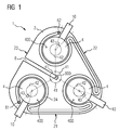
- FIG. 1 is a schematic plan view of the coil device 1 according to the invention shown.
- the coil device 1 comprises a cooling plate 2, which has a cooling channel 24.
- the cooling channel 24 is designed and provided for guiding a coolant, for example water or a fluid, which in particular comprises a fluoroketone.
- the cooling channel 24 has a flow 61 and a return 62.
- the cooling plate 2 of the coil device 1 is formed like a triangle.
- the cooling plate 2 has three side edges 21, 22, 23, which form the sides of an imaginary isosceles triangle.
- the corners of the imaginary isosceles triangle are here rounded, so space is saved.
- eddy currents within the cooling plate 2 can be reduced by the rounded corners.
- a recess 8 which is formed as a slot, is provided.
- the slot 8, which is elongated extends from a center 800 of the cooling plate 2, in particular a center of symmetry of the cooling plate 2, to the third side edge 23 of the cooling plate 2. Furthermore, the recess 8 lies between two sections of the cooling channel 24.
- the coil device 1 has three coil windings 4, which in the illustrated figure in its cross section circular are formed. Furthermore, the coil windings 4 have an end face 400 which is formed, for example, by an end face of a winding core, which is assigned to the respective coil winding 4.
- the coil windings 4 are arranged symmetrically to each other.
- the coil windings 4 are spatially offset by the angle 41 of 2 ⁇ / 3 to each other.
- the angle 41 refers to the common center 800.
- the coil windings 4 are arranged substantially in the region of the rounded corners of the triangular-type cooling plate 2.
- the cooling channel 24 extends at least partially along the coil windings 4.
- the cooling channel 24 preferably extends approximately completely along the coil windings 4. In other words, the coil windings 4 are surrounded by the cooling channel 24 up to an angle 43.
- the cooling channel extends at least over an angle 42 of at least 5 ⁇ / 3, in particular of at least 11 ⁇ / 3, more preferably of 2 ⁇ about the respective coil winding 4.
- the angle 43 leads to a recess of an angular range of the coil winding 4, the is not surrounded by the cooling channel 24 and corresponds to the angle 43. In other words, an angle sum formed from the angle 42 and the angle 43 has the value 2 ⁇ .
- the angle range, which corresponds to the angle 43 can be provided for an electrical contacting by means of contacting elements 10, in particular by means of a bent copper tab.
- a preferred heat dissipation of the coil devices 4 is advantageously made possible by means of the cooling plate 2.
- the mechanical stability of the coil device 1 is increased and improved by the cooling plate 2.
- space and weight can be saved. In other words is made possible by the cooling plate 2, a compression of the coil device 1.
- the said compression of the cooling plate 2 with the end faces 400 of the coil devices 4 is facilitated.
- FIG. 2 shows a plan view of a coil device 1 according to the invention, which is comparable to the in FIG. 1 is shown coil device. In other words, that can be under FIG. 1 Said on FIG. 2 applied and transmitted.
- the coil device 1 in FIG. 2 has a T-shaped or T-shaped cooling plate 2.
- FIG. 2 shows FIG. 2 A more complex arrangement and extension of the cooling channel 24. This extends meandering within the cooling plate 2 to the coil devices 4.
- An advantage of the meandering arrangement of the cooling channel 24 is that thereby the cooling of the cooling plate 2 and thus the coil device 1 is improved.
- the flow 61 and the return 62 of the cooling channel 24 can be arranged in a common region of the cooling plate 2, so that their fluidic contacting is simplified.
- FIG. 1 includes the coil device in FIG. 2 a recess 8 which extends radially outward from a center 800.
- a circular recess is provided within the center 800.
- FIG. 3 a further plan view of a coil device 1 according to the invention is shown. This shows FIG. 3 essentially the same elements as before FIG. 1 and or FIG. 2 ,
- FIG. 3 unlike the FIGS. 1 and / or 2 a star-shaped or star-shaped cooling plate 2.
- the cooling plate 2 in turn has a cooling channel 24, which extends at least partially around the coil windings 4 of the coil devices 1.
- the flow 61 and return 62 of the cooling channel 24 are arranged within a common area, so that their fluidic contact is facilitated and improved.
- the coil device 1 has a recess 8, which is formed star-like or star-shaped.
- this has a plurality of elongated slots 81 which extend from the common center 800 in different directions.
- This significantly reduces the formation of eddy currents.
- One of the slots 81 is in this case arranged between the flow 61 and the return 62 of the cooling channel 24. In other words, the lead 61 and the return 62 are spaced by one of the slots 81.
- the dashed lines correspond to an alternative extent of the cooling channel 24.
- the cooling channel 24 extends in the manner of a tab between in each case two adjacent slots 81. This advantageously improves the cooling of the coil apparatus.
- the coil device 1 contacting elements 10, in particular copper tabs, which are arranged between the coil devices 4 and the cooling channel 24.
- the cooling channel 24 extends along the contacting elements 10, so that they are cooled by the cooling channel 24 or by a coolant, which is arranged within the cooling channel 24 or flows through it.
- FIG. 4 is a side sectional view of a portion of a coil device 1 according to the invention shown.
- one of the coil devices 4 and the cooling plate 24 can be seen in the illustrated section.
- an electrically insulating coating 14 is arranged or applied. This is used for electrical insulation of the cooling plate 24 with respect to the voltage-carrying components of the coil winding 4.
- the electrical insulating material or the insulating coating 14 for example, from a little water-absorbing plastic, in particular PPS, or a ceramic, such as aluminum nitride, be formed.
- an arrangement by means of a silicone layer is advantageous because unevenness of the coil winding 4 and / or the cooling plate 24 can be compensated.
- a further electrically insulating layer or coating 16 is attached on a side facing away from the coil winding 4 of the cooling plate 2.
- the electrically insulating layer 14 may be formed from a plastic which absorbs little water, for example PPS, or from a ceramic, for example aluminum nitrite.
- the further electrically insulating layer 16 is provided for electrical insulation with respect to an iron yoke 12 of the coil device 1.
Landscapes
- Engineering & Computer Science (AREA)
- Power Engineering (AREA)
- Coils Of Transformers For General Uses (AREA)
Abstract
Description
- Die Erfindung betrifft eine Spulenvorrichtung gemäß dem Oberbegriff des Patentanspruches 1.
- Aus dem Stand der Technik ist eine Mehrzahl von Spulenvorrichtungen, beispielsweise Drosselspulen, die aus mehreren Lagen eines isolierten Leiters gewickelt werden, bekannt. Aufgrund der elektrischen Beanspruchung einer Spulenvorrichtung treten thermische Verluste, beispielsweise innerhalb der Wicklungen der Spulenvorrichtung oder in ihrem Spulenkern, der beispielsweise aus Eisen gebildet ist, auf. Typischerweise werden die einzelnen Wicklungen der Spulenvorrichtung durch die Einbringung eines Isolationsmaterials elektrisch voneinander isoliert. Hierbei ist eine ausreichend gute Entwärmung der Spulenvorrichtung sicherzustellen. Eine bevorzugte Entwärmung oder Kühlung der Spulenvorrichtung beziehungsweise ihrer Wicklungslagen ist kontaktdimensioniert, sodass der vorgegebene Bauraum möglichst optimal ausgenutzt werden kann. Hierzu wird beispielsweise eine Kühlplatte in die Spulenvorrichtung eingebracht, die insbesondere gegenüber einem Joch einer Wicklung der Spulenvorrichtung elektrisch isoliert werden muss. Die Einbringung einer Kühlplatte, insbesondere einer metallischen Kühlplatte, innerhalb der Spulenvorrichtung hat jedoch den Nachteil, dass aufgrund der auftretenden Magnetfelder elektrische Ströme in dieser induziert werden, die zu Verlusten führen (ohmsche Verluste durch Wirbelströme).
- Weiterhin sind aus dem Stand der Technik Wasserkühlungen bekannt, die insbesondere für Drosselspulen verwendet werden, und auf einer Einbringung von metallischen Kühlkörpern in die Spulenvorrichtung basieren.
- Aus dem Stand der Technik sind Hohlleiter bekannt, die für die Wicklungen der Spulenvorrichtung eingesetzt werden. Durch die Hohleiter kann ein Kühlmittel geführt werden, das die Spulenvorrichtung entwärmt.
- Aus der
DE 10 2012 217 607 A1 sind Kühltaschen aus Kunststoff mit einer Y-Struktur bekannt, die in die Spulenvorrichtung oder einer ihrer Wicklungen eingebracht werden kann. Um die thermische Leitfähigkeit zwischen den Wicklungen der Spulenvorrichtung und der genannten Y-Struktur zu erhöhen, werden diese wenigstens zum Teil in einem Harz eingebettet, sodass Lufteinschlüsse vermindert oder bestenfalls verhindert werden können. Weiterhin ist es bekannt Spulenvorrichtungen, insbesondere Drosselspulen, vollständig zu vergießen, sodass eine verbesserte interne thermische Leitfähigkeit erreicht wird. - Aus der
EP 2977996 A1 ist eine Drosselspule eines Stromrichters bekannt, die eine hohlzylindrische Spulenwicklung aufweist an deren Deckfläche eine Kühlplatte thermisch angebunden ist. Hierbei besteht der Nachteil, dass sich innerhalb der Kühlplatte Wirbelströme ausbilden, die zu Verlusten führen. Weiterhin hat sich herausgestellt, dass eine Kühlung der Kühlplatte zu ihrer Entwärmung technisch schwierig ist. - Der vorliegenden Erfindung liegt die Aufgabe zu Grunde, eine Spulenvorrichtung mit einer verbesserten Kühlung bereitzustellen.
- Die Aufgabe wird durch eine Spulenvorrichtung mit den Merkmalen des unabhängigen Patentanspruches 1 gelöst. In den abhängigen Patentansprüchen sind vorteilhafte Ausgestaltungen und Weiterbildungen der Erfindung angegeben.
- Die erfindungsgemäße Spulenvorrichtung für einen Stromrichter, umfasst eine Kühlplatte und eine Mehrzahl N von Spulenwicklungen, wobei die Kühlplatte mit wenigstens einer Stirnseite einer der Spulenwicklungen thermisch gekoppelt ist. Erfindungsgemäß sind die Spulenwicklungen räumlich um einen Winkel von 2π/N (= 360°/N) versetzt zueinander angeordnet und die Kühlplatte weist einen Kühlkanal auf, der sich wenigstens teilweise um jede der Spulenwicklungen erstreckt.
- Mit anderen Worten weist die Spulenvorrichtung wenigstens zwei Spulenwicklungen auf. Hierbei erstreckt sich der Kühlkanal um jede der zwei Spulenwicklungen. Dadurch wird vorteilhafterweise eine verbesserte Entwärmung der Spulenwicklungen sichergestellt. Hierbei ist besonders die Stirnseite der Spulenwicklung bevorzugt, da diese typischerweise eine ausreichend große Fläche aufweist und somit besonders gut für die Entwärmung der Spulenwicklungen geeignet ist.
- Durch den erfindungsgemäßen symmetrischen Aufbau der Spulenvorrichtung, der durch die räumliche Anordnung der Spulenwicklungen in einem Winkel von 2π/N gegeben ist, ergibt sich eine elektromagnetisch vorteilhafte Anordnung, die insbesondere auch für die Kühlung der Spulenvorrichtung besonders bevorzugt ist.
- Die Kühlplatte sowie ihr Kühlkanal können beispielsweise mittels eines regenerativen Verfahrens, insbesondere eines 3D-Drucks, gefertigt sein. Weiterhin ist der Kühlkanal dazu geeignet ein Kühlmittel, beispielsweise Wasser, insbesondere ein Fluorketon, zur Kühlung oder Entwärmung der Spulenvorrichtung aufzunehmen. Besonders bevorzugt ist das für die Kühlung vorgesehene Kühlmittel elektrisch nicht leitend. Dadurch können vorteilhafterweise Wirbelströme innerhalb der Kühlplatte verringert werden.
- Ein weiterer Vorteil der vorliegenden Erfindung ist, dass alle Spulenwicklungen der Spulenvorrichtung mittels eines gemeinsamen Kühlkanals entwärmt werden. Hierbei erstreckt sich erfindungsgemäß der Kühlkanal wenigstens teilweise um jede der Spulenwicklungen. Dadurch lässt sich eine mechanisch vorteilhafte und kompakte Bauweise der Spulenvorrichtung erreichen. Weiterhin wird durch die Kühlplatte die mechanische Stabilität der Spulenvorrichtung verbessert. Beispielsweise kann die Spulenvorrichtung mittels der Kühlplatte oder mittels einer Mehrzahl von Kühlplatten verpresst werden, sodass sich das Gewicht der erfindungsgemäßen Spulenvorrichtung verringert und zusätzlich Bauraum eingespart werden kann.
- Gemäß einer besonders vorteilhaften Ausgestaltung der Erfindung umfasst die Spulenvorrichtung genau drei Spulenwicklungen.
- Dadurch wird eine besonders bevorzugte symmetrische Ausgestaltung der Spulenvorrichtung bereitgestellt. Insbesondere entsprechen die drei Spulenwicklungen den drei bekannten Phasen des Drei-Phasen-Wechselstromes. Mit anderen Worten ist für jede Phase des Drei-Phasen-Wechselstromes eine Spulenvorrichtung vorgesehen. Die erfindungsgemäße Spulenvorrichtung kann somit für einen Stromrichter, insbesondere einen Umrichter, vorgesehen sein.
- Weiterhin erfolgt hierbei die Erstreckung des Kühlkanals derart, dass dieser sich möglichst lange und möglichst nahe um die Spulenwicklungen erstreckt. Dadurch wird vorteilhafterweise die Entwärmung der Spulenvorrichtung mittels der Kühlplatte verbessert.
- Besonders bevorzugt ist es hierbei, wenn sich der Kühlkanal über einen Winkel von wenigstens 5π/3 (=300°), insbesondere von 11π/6 (= 330°), besonders bevorzugt von 2π (= 360°), um die jeweilige Spulenwicklung erstreckt.
- Mit anderen Worten ergibt sich bevorzugt ein Winkelbereich von höchstens π/3 (=60°), insbesondere von höchstens π/6 (=30°), um die Spulenwicklung, in welchem der Kühlkanal diese nicht umschließt. Vorteilhafterweise wird dadurch die Entwärmung der Spulenvorrichtung, insbesondere ihrer Spulenwicklungen, weiter verbessert.
- In einer bevorzugten Ausgestaltung der Erfindung ist der Querschnitt des Kühlkanals im Bereich der Spulenwicklung vergrößert.
- Durch den vergrößerten Querschnitt des Kühlkanals im Bereich der Spulenwicklung kann vorteilhafterweise mehr Wärme von den Spulenwicklungen abgeführt werden. Insgesamt wird dadurch die Entwärmung der Spulenvorrichtung beziehungsweise der Spulenwicklungen weiter verbessert.
- Gemäß einer vorteilhaften Ausgestaltung der Erfindung ist die Kühlplatte dreiecksartig oder dreiecksförmig ausgebildet.
- Vorteilhafterweise ergibt sich dadurch eine symmetrische Ausgestaltung der Kühlplatte, die besonders für genau drei Spulenwicklungen von Vorteil ist. Somit ist die geometrische Form beziehungsweise die geometrische Ausgestaltung der Kühlplatte an genau drei Spulenwicklungen angepasst. Dadurch kann vorteilhafterweise Bauraum eingespart werden. Insbesondere ist es hierbei vorgesehen, dass die Ecken der dreiecksartigen oder dreiecksförmigen ausgebildeten Kühlplatte abgerundet sind, sodass weiterer Bauraum eingespart werden kann.
- Hierbei ist es besonders bevorzugt, wenn die Kühlplatte drei Seitenränder aufweist, wobei sich der Kühlkanal entlang zwei Seitenrändern der drei Seitenränder erstreckt.
- Dadurch wird vorteilhafterweise die Wärme über wenigstens zwei der Seitenränder an die Umgebung der Kühlplatte abgegeben. An dem weiteren Seitenrand, an welchem sich der Kühlkanal nicht erstreckt, können vorteilhafterweise der Vorlauf und der Rücklauf für den Kühlkanal und/oder weitere mechanische, elektrische, thermische und/oder fluidische Anschlüsse für die Spulenvorrichtung vorgesehen sein.
- In einer vorteilhaften Ausgestaltung der Erfindung weist die Kühlplatte wenigstens eine Aussparung, insbesondere einen Schlitz, auf.
- Vorteilhafterweise können dadurch das Auftreten von Wirbelströmen und deren Auswirkungen verringert werden. Hierdurch wird vorteilhafterweise die Entwärmung der Spulenvorrichtung sowie der Kühlplatte verbessert. Weiterhin wird die Effizienz einer elektrischen Maschine, die beispielsweise die Spulenvorrichtung umfasst, verbessert.
- Hierbei ist es besonders bevorzugt, wenn die Aussparung sternenartig oder sternenförmig ausgebildet ist.
- Dadurch wird eine besonders vorteilhafte Verminderung von Wirbelströmen innerhalb der Kühlplatte erreicht.
- Weiterhin ist es hierbei bevorzugt, wenn die Aussparung aus einer Mehrzahl von Schlitzen gebildet ist, wobei sich die Schlitze, ausgehend von einem gemeinsamen Zentrum, sternenartig in verschiedene Richtungen erstrecken.
- Gemäß einer besonders bevorzugten Ausgestaltung der Erfindung erstreckt sich hierbei der Kühlkanal laschenartig zwischen den Schlitzen.
- Vorteilhafterweise wird dadurch die Entwärmung der Kühlplatte verbessert sowie eine Verminderung von Wirbelströmen erreicht. Das ist deshalb der Fall, da durch die laschenartige Erstreckung des Kühlkanals seine Länge vergrößert und somit mehr Wärme übertragen werden kann.
- In einer weiteren vorteilhaften Ausgestaltung der Erfindung ist die Kühlplatte an Wicklungskernen der Spulenwicklungen angeordnet, wobei eine den Wicklungskernen zugewandte Seitenfläche der Kühlplatte eine elektrisch isolierende Schicht oder Beschichtung aufweist.
- Mit anderen Worten ist die Kühlplatte wenigstens zweiteilig aufgebaut. Der erste Teil der Kühlplatte, der den Kühlkanal umfasst, ist beispielsweise aus Aluminium und/oder Kupfer, das heißt einem metallischen und gut wärmeleitenden Material gebildet. Ein zweiter Teil der Kühlplatte ist mittels der elektrisch isolierenden Schicht beziehungsweise Beschichtung gebildet. Hierzu ist es von Vorteil Noryl und/oder Ryton für die elektrisch isolierende Schicht oder die Beschichtung vorzusehen. Vorteilhafterweise kann dadurch die Kühlplatte gegenüber spannungsführenden Teilen der Spulenvorrichtung elektrisch isoliert werden.
- Weiterhin kann für die elektrisch isolierende Schicht ein elektrisch isolierendes Thermal-Interface-Material (TIM) vorgesehen sein. Zudem ist die Verwendung von wenigwasseraufnehmenden Kunststoffen, insbesondere von PPS oder einer Keramik, beispielsweise Aluminiumnitrit, von Vorteil. Dadurch wird insgesamt ein kosteneffizienter Aufbau der Spulenvorrichtung ermöglicht, bei dem die Führung eines Kühlmittels im metallischen Teil der Kühlplatte (erster Teil) angeordnet ist und die elektrisch isolierenden Bauteile der Kühlplatte, das heißt die elektrisch isolierende Schicht, durch einfache Abschlussplatten ohne Kontaktierung und Konturierung ausgebildet sind.
- Hierbei ist es bevorzugt wenn, beispielsweise wie vorstehend ausgeführt, eine dem Wicklungskern abgewandte Seitenfläche der Kühlplatte eine elektrisch isolierende Schicht oder Beschichtung aufweist.
- Dadurch können die Wicklungskerne sowie die Spulenwicklungen der Spulenvorrichtung gegenüber einem Joch, insbesondere einem Eisenjoch, isoliert werden.
- Gemäß einer vorteilhaften Ausgestaltung der Erfindung ist die Kühlplatte aus Aluminium, Kupfer, Edelstahl oder Kupfernickelferrit oder einer Mischung hieraus gebildet.
- Hierbei kann die Kühlplatte weitere Materialien oder Stoffe umfassen, beispielsweise Kunststoffe, insbesondere PPS oder eine Keramik, beispielsweise Aluminiumnitrid. Die genannten metallischen Werkstoffe, das heißt Aluminium, Kupfer, Edelstahl oder Kupfernickelferrit weisen vorteilhafterweise eine hohe Wärmeleitfähigkeit auf, sodass die thermische Entwärmung der Spulenvorrichtung beziehungsweise der Kühlplatte verbessert wird.
- In einer vorteilhaften Weiterbildung der Erfindung weist jede der Spulenwicklungen ein Kontaktierungselement zur elektrischen Kontaktierung auf, wobei jedes der Kontaktierungselemente wenigstens teilweise vom Kühlkanal umgeben ist.
- Vorteilhafterweise wird dadurch die Entwärmung der Spulenvorrichtung sowie der Kühlplatte weiter verbessert. Insbesondere werden hierdurch die Kontaktierungselemente ebenso durch den Kühlkanal, der diese wenigstens teilweise umgibt, wenigstens teilweise entwärmt.
- Bevorzugt sind die Kontaktierungselemente hierbei als Kupferlaschen, insbesondere als gebogene Kupferlaschen, ausgebildet.
- Vorteilhafterweise wird dadurch die elektrische Kontaktierung der Spulenvorrichtung verbessert sowie die thermische Leitfähigkeit der Kontaktierungselemente erhöht.
- Weitere Vorteile, Merkmale und Einzelheiten der Erfindung ergeben sich aus den im Folgenden beschriebenen Ausführungsbeispielen sowie anhand der Zeichnungen. Dabei zeigen schematisiert:
- Figur 1
- eine schematische Draufsicht einer erfindungsgemäßen Spulenvorrichtung mit einer dreiecksartigen Kühlplatte;
- Figur 2
- eine weitere schematische Draufsicht einer erfindungsgemäßen Spulenvorrichtung, wobei eine Kühlplatte der Spulenvorrichtung T-förmig ausgebildet ist;
- Figur 3
- eine weitere Draufsicht einer erfindungsgemäßen Spulenvorrichtung, wobei hierbei die Kühlplatte sternenartig ausgebildet ist;
- Figur 4
- eine seitliche Darstellung einer erfindungsgemäßen Spulenvorrichtung.
- Gleichartige, gleichwertige oder gleichwirkende Elemente können in den Figuren mit denselben Bezugszeichen versehen sein.
- In
Figur 1 ist eine schematische Draufsicht der erfindungsgemäßen Spulenvorrichtung 1 dargestellt. Hierbei umfasst die Spulenvorrichtung 1 eine Kühlplatte 2, die einen Kühlkanal 24 aufweist. Der Kühlkanal 24 ist zur Führung eines Kühlmittels, beispielsweise von Wasser oder eines Fluids, das insbesondere ein Fluorketon umfasst, ausgebildet und vorgesehen. Hierzu weist der Kühlkanal 24 einen Vorlauf 61 sowie einen Rücklauf 62 auf. - Die Kühlplatte 2 der Spulenvorrichtung 1 ist dreiecksartig ausgebildet. Hierbei weist die Kühlplatte 2 drei Seitenränder 21, 22, 23 auf, die die Seiten eines gedachten gleichschenkligen Dreieckes ausbilden. Die Ecken des gedachten gleichschenkligen Dreieckes sind hierbei abgerundet, sodass Bauraum eingespart wird. Zudem können durch die abgerundeten Ecken Wirbelströme innerhalb der Kühlplatte 2 verringert werden.
- Zur weiteren Verringerung von Wirbelströmen ist eine Aussparung 8, die als Schlitz ausgebildet ist, vorgesehen. Hierbei erstreckt sich der Schlitz 8, der länglich ausgebildet ist, von einem Zentrum 800 der Kühlplatte 2, insbesondere einem Symmetriezentrum der Kühlplatte 2, zum dritten Seitenrand 23 der Kühlplatte 2. Weiterhin liegt die Aussparung 8 zwischen zwei Abschnitten des Kühlkanals 24.
- Die Spulenvorrichtung 1 weist drei Spulenwicklungen 4 auf, die in der dargestellten Figur in ihrem Querschnitt kreisförmig ausgebildet sind. Weiterhin weisen die Spulenwicklungen 4 eine Stirnseite 400 auf, die beispielsweise durch eine Stirnseite eines Wicklungskerns, der der jeweiligen Spulenwicklung 4 zugeordnet ist, ausgebildet ist.
- Die Spulenwicklungen 4 sind symmetrisch zueinander angeordnet. Hierbei weisen die Spulenwicklungen 4 einen Winkel 41 von 2π/3 (=120°) zueinander auf. Mit anderen Worten sind die Spulenwicklungen 4 räumlich um den Winkel 41 von 2π/3 versetzt zueinander angeordnet. Hierbei bezieht sich der Winkel 41 auf das gemeinsame Zentrum 800. Mit anderen Worten sind die Spulenwicklungen 4 im Wesentlichen im Bereich der abgerundeten Ecken der dreiecksartigen Kühlplatte 2 angeordnet.
- Der Kühlkanal 24 erstreckt sich wenigstens teilweise entlang der Spulenwicklungen 4. Bevorzugt erstreckt sich der Kühlkanal 24 annähernd vollständig entlang der Spulenwicklungen 4. Mit anderen Worten sind die Spulenwicklungen 4 bis auf einen Winkel 43 von dem Kühlkanal 24 umgeben. Entsprechend dem Winkel 43 erstreckt sich der Kühlkanal wenigstens über einen Winkel 42 von wenigstens 5π/3, insbesondere von wenigstens 11π/3, besonders bevorzugt von 2π um die jeweilige Spulenwicklung 4. Der Winkel 43 führt zu einer Aussparung eines Winkelbereiches der Spulenwicklung 4, der nicht von dem Kühlkanal 24 umgeben ist und dem Winkel 43 entspricht. Mit anderen Worten weist eine aus dem Winkel 42 und dem Winkel 43 gebildete Winkelsumme den Wert 2π auf. Der Winkelbereich, der dem Winkel 43 entspricht, kann für eine elektrische Kontaktierung mittels Kontaktierungselementen 10, insbesondere mittels einer gebogenen Kupferlasche, vorgesehen sein.
- Durch den Verlauf des Kühlkanals 24 wird vorteilhafterweise eine bevorzugte Entwärmung der Spulenvorrichtungen 4 mittels der Kühlplatte 2 ermöglicht. Zudem wird durch die Kühlplatte 2 die mechanische Stabilität der Spulenvorrichtung 1 erhöht und verbessert. Weiterhin kann durch ein Zusammendrücken der Spulenvorrichtung 1, beispielsweise mittels der Kühlplatte 2, Bauraum und Gewicht eingespart werden. Mit anderen Worten wird durch die Kühlplatte 2 eine Verpressung der Spulenvorrichtung 1 ermöglicht. Zudem wird die genannte Verpressung der Kühlplatte 2 mit den Stirnseiten 400 der Spulenvorrichtungen 4 erleichtert.
-
Figur 2 zeigt eine Draufsicht einer erfindungsgemäßen Spulenvorrichtung 1, die vergleichbar mit der inFigur 1 dargestellten Spulenvorrichtung ist. Mit anderen Worten kann das unterFigur 1 Gesagte aufFigur 2 angewandt und übertragen werden. - Die Spulenvorrichtung 1 in
Figur 2 weist eine T-artige oder T-förmige Kühlplatte 2 auf. Zudem zeigtFigur 2 eine komplexere Anordnung und Erstreckung des Kühlkanals 24. Dieser erstreckt sich mäanderartig innerhalb der Kühlplatte 2 um die Spulenvorrichtungen 4. Ein Vorteil der mäanderartigen Anordnung des Kühlkanal 24 ist, dass dadurch die Entwärmung der Kühlplatte 2 und somit der Spulenvorrichtung 1 verbessert wird. Zudem können der Vorlauf 61 sowie der Rücklauf 62 des Kühlkanals 24 in einem gemeinsamen Bereich der Kühlplatte 2 angeordnet werden, sodass deren fluidische Kontaktierung vereinfacht wird. - Wie bereits in
Figur 1 weist die Spulenvorrichtung inFigur 2 eine Aussparung 8 auf, die sich von einem Zentrum 800 radial nach außen erstreckt. Hierbei ist eine kreisförmige Aussparung innerhalb des Zentrums 800 vorgesehen. Dadurch wird ein Aufstecken der Kühlplatte 2 auf eine gemeinsame Achse, die zur Anordnung der Spulenvorrichtungen 4 vorgesehen ist, ermöglicht. Weiterhin wird dadurch eine Verpressung der Kühlplatte 2 mit den Stirnseiten 400 der Spulenvorrichtungen 4 erleichtert. - In
Figur 3 ist eine weitere Draufsicht einer erfindungsgemäßen Spulenvorrichtung 1 dargestellt. Hierbei zeigtFigur 3 im Wesentlichen die gleichen Elemente wie bereitsFigur 1 und/oderFigur 2 . -
Figur 3 weist im Unterschied zu denFiguren 1 und/oder 2 eine sternenartig oder sternenförmig ausgebildete Kühlplatte 2 auf. Vorteilhafterweise kann dadurch weiterer Bauraum eingespart werden. Die Kühlplatte 2 weist wiederum einen Kühlkanal 24 auf, der sich wenigstens teilweise um die Spulenwicklungen 4 der Spulenvorrichtungen 1 erstreckt. Hierbei sind der Vorlauf 61 sowie Rücklauf 62 des Kühlkanals 24 innerhalb eines gemeinsamen Bereiches angeordnet, sodass deren fluidische Kontaktierung erleichtert und verbessert wird. - Die Spulenvorrichtung 1 weist eine Aussparung 8 auf, die sternenartig oder sternenförmig ausgebildet ist. Hierzu weist diese eine Mehrzahl von länglichen Schlitzen 81 auf, die sich von dem gemeinsamen Zentrum 800 in verschiedene Richtungen erstrecken. Vorteilhafterweise wird dadurch die Ausbildung von Wirbelströmen deutlich verringert. Einer der Schlitze 81 ist hierbei zwischen dem Vorlauf 61 und dem Rücklauf 62 des Kühlkanals 24 angeordnet. Mit anderen Worten sind der Vorlauf 61 und der Rücklauf 62 durch einen der Schlitze 81 beabstandet.
- Die gestrichelten Linien entsprechen einer alternativen Erstreckung des Kühlkanals 24. Hierbei erstreckt sich der Kühlkanal 24 laschenartig zwischen jeweils zwei benachbarten Schlitze 81. Dadurch wird vorteilhafterweise die Entwärmung der Spulenvorrichtung verbessert.
- Weiterhin weist die Spulenvorrichtung 1 Kontaktierungselemente 10, insbesondere Kupferlaschen, auf, die zwischen den Spulenvorrichtungen 4 und dem Kühlkanal 24 angeordnet sind. Hierbei erstreckt sich der Kühlkanal 24 entlang der Kontaktierungselemente 10, sodass diese durch den Kühlkanal 24 beziehungsweise durch ein Kühlmittel, welches innerhalb des Kühlkanals 24 angeordnet ist oder diesen durchströmt, gekühlt werden.
- In
Figur 4 ist eine seitliche Schnittdarstellung eines Teils einer erfindungsgemäßen Spulenvorrichtung 1 dargestellt. - Hierbei ist im dargestellten Schnitt eine der Spulenvorrichtungen 4 sowie die Kühlplatte 24 zu erkennen. Auf einer der Spulenwicklung 4 zugewandten Seite der Kühlplatte 24 ist eine elektrisch isolierende Beschichtung 14 angeordnet oder aufgebracht. Diese dient zur elektrischen Isolierung der Kühlplatte 24 gegenüber den spannungstragenden Bauteilen der Spulenwicklung 4. Hierbei kann das elektrische isolierende Material beziehungsweise die isolierende Beschichtung 14 beispielsweise aus einem wenig wasseraufnehmenden Kunststoff, insbesondere PPS, oder einer Keramik, beispielsweise Aluminiumnitrit, gebildet sein. Weiterhin ist eine Anordnung mittels einer Silikonschicht von Vorteil, da dadurch Unebenheiten der Spulenwicklung 4 und/oder der Kühlplatte 24 ausgeglichen werden können.
- Auf einer der Spulenwicklung 4 abgewandten Seite der Kühlplatte 2 ist eine weitere elektrisch isolierende Schicht oder Beschichtung 16 angebracht. Wie bereits die elektrisch isolierende Schicht 14 kann diese aus einem wenig wasseraufnehmenden Kunststoff, beispielsweise PPS, oder einer Keramik, beispielsweise Aluminiumnitrit, gebildet sein. Die weitere elektrisch isolierende Schicht 16 ist zur elektrischen Isolierung gegenüber einem Eisenjoch 12 der Spulenvorrichtung 1 vorgesehen.
- Obwohl die Erfindung im Detail durch die bevorzugten Ausführungsbeispiele näher illustriert und beschrieben wurde, so ist die Erfindung nicht durch die offenbarten Beispiele eingeschränkt oder andere Variationen können vom Fachmann hieraus abgeleitet werden, ohne den Schutzumfang der Erfindung zu verlassen.
Claims (15)
- Spulenvorrichtung (1) für einen Stromrichter, umfassend eine Kühlplatte (2) und eine Mehrzahl N von Spulenwicklungen (4), wobei die Kühlplatte (2) mit wenigstens einer Stirnseite (400) einer der Spulenwicklungen (4) thermisch gekoppelt ist, dadurch gekennzeichnet, dass die Spulenwicklungen (4) räumlich um einen Winkel (41) von 2π/N versetzt zueinander angeordnet sind, und die Kühlplatte (2) einen Kühlkanal (24) aufweist, der sich wenigstens teilweise um jede der N Spulenwicklungen (4) erstreckt.
- Spulenvorrichtung (1) gemäß Anspruch 1, dadurch gekennzeichnet, dass diese genau drei Spulenwicklungen (4) umfasst.
- Spulenvorrichtung (1) gemäß Anspruch 1 oder 2, dadurch gekennzeichnet, dass sich der Kühlkanal (6) über einen Winkel (42) von wenigstens 5π/3, insbesondere von wenigstens 11π/6, besonders bevorzugt von 2π, um die jeweilige Spulenwicklung (4) erstreckt.
- Spulenvorrichtung (1) gemäß einem der vorhergehenden Ansprüche, dadurch gekennzeichnet, dass der Querschnitt des Kühlkanals (24) im Bereich der Spulenwicklungen (4) vergrößert ist.
- Spulenvorrichtung (1) gemäß einem der vorhergehenden Ansprüche, dadurch gekennzeichnet, dass die Kühlplatte (2) dreiecksartig oder dreiecksförmig ausgebildet ist.
- Spulenvorrichtung (1) gemäß Anspruch 5, dadurch gekennzeichnet, dass die Kühlplatte (2) drei Seitenränder (21, 22, 23) aufweist, wobei sich der Kühlkanal (24) entlang zwei Seitenrändern (21, 22) der drei Seitenränder (21, 22, 23) erstreckt.
- Spulenvorrichtung (1) gemäß einem der vorhergehenden Ansprüche, dadurch gekennzeichnet, dass die Kühlplatte (2) wenigstens eine Aussparung (8), insbesondere einen Schlitz, aufweist.
- Spulenvorrichtung (1) gemäß Anspruch 7, dadurch gekennzeichnet, dass die Aussparung (8) sternenartig oder sternenförmig ausgebildet ist.
- Spulenvorrichtung (1) gemäß Anspruch 8, dadurch gekennzeichnet, dass die Aussparung (8) aus einer Mehrzahl von Schlitzen (81) gebildet ist, wobei sich die Schlitze (81) ausgehend von einem gemeinsamen Zentrum (800) sternenartig in verschiedene Richtungen erstrecken.
- Spulenvorrichtung (1) gemäß Anspruch 9, dadurch gekennzeichnet, dass sich der Kühlkanal (24) laschenartig zwischen den Schlitzen (81) erstreckt.
- Spulenvorrichtung (1) gemäß einem der vorhergehenden Ansprüche, dadurch gekennzeichnet, dass die Kühlplatte (2) an Wicklungskernen der Spulenwicklungen (4) angeordnet ist, wobei eine den Wicklungskernen zugewandte Seitenfläche der Kühlplatte (2) eine elektrisch isolierende Schicht (14) oder Beschichtung aufweist.
- Spulenvorrichtung (1) gemäß Anspruch 11, dadurch gekennzeichnet, dass eine den Wicklungskernen abgewandte Seitenfläche der Kühlplatte (2) eine elektrisch isolierende Schicht (16) oder Beschichtung aufweist.
- Spulenvorrichtung (1) gemäß einem der vorhergehenden Ansprüche, dadurch gekennzeichnet, dass die Kühlplatte (2) aus Aluminium, Kupfer, Edelstahl oder Kupfer-Nickel-Ferrit oder einer Mischung hieraus gebildet ist.
- Spulenvorrichtung (1) gemäß einem der vorhergehenden Ansprüche, dadurch gekennzeichnet, dass jede der Spulenwicklungen (4) ein Kontaktierungselement (10) zur elektrischen Kontaktierung aufweist, wobei jedes der Kontaktierungselemente (10) wenigstens teilweise vom Kühlkanal (24) umgeben ist.
- Spulenvorrichtung (1) gemäß Anspruch 14, dadurch gekennzeichnet, dass die Kontaktierungselemente (10) als Kupferlaschen ausgebildet sind.
Priority Applications (5)
| Application Number | Priority Date | Filing Date | Title |
|---|---|---|---|
| EP16185586.1A EP3288046B1 (de) | 2016-08-25 | 2016-08-25 | Spulenvorrichtung |
| EP17752092.1A EP3455863A1 (de) | 2016-08-25 | 2017-08-08 | Spulenvorrichtung |
| CN201780051258.6A CN109643600B (zh) | 2016-08-25 | 2017-08-08 | 线圈装置 |
| PCT/EP2017/070011 WO2018036805A1 (de) | 2016-08-25 | 2017-08-08 | Spulenvorrichtung |
| US16/327,096 US11443882B2 (en) | 2016-08-25 | 2017-08-08 | Coil device |
Applications Claiming Priority (1)
| Application Number | Priority Date | Filing Date | Title |
|---|---|---|---|
| EP16185586.1A EP3288046B1 (de) | 2016-08-25 | 2016-08-25 | Spulenvorrichtung |
Publications (2)
| Publication Number | Publication Date |
|---|---|
| EP3288046A1 true EP3288046A1 (de) | 2018-02-28 |
| EP3288046B1 EP3288046B1 (de) | 2021-04-14 |
Family
ID=56800207
Family Applications (2)
| Application Number | Title | Priority Date | Filing Date |
|---|---|---|---|
| EP16185586.1A Active EP3288046B1 (de) | 2016-08-25 | 2016-08-25 | Spulenvorrichtung |
| EP17752092.1A Withdrawn EP3455863A1 (de) | 2016-08-25 | 2017-08-08 | Spulenvorrichtung |
Family Applications After (1)
| Application Number | Title | Priority Date | Filing Date |
|---|---|---|---|
| EP17752092.1A Withdrawn EP3455863A1 (de) | 2016-08-25 | 2017-08-08 | Spulenvorrichtung |
Country Status (4)
| Country | Link |
|---|---|
| US (1) | US11443882B2 (de) |
| EP (2) | EP3288046B1 (de) |
| CN (1) | CN109643600B (de) |
| WO (1) | WO2018036805A1 (de) |
Cited By (1)
| Publication number | Priority date | Publication date | Assignee | Title |
|---|---|---|---|---|
| WO2020101905A1 (en) * | 2018-11-12 | 2020-05-22 | Carrier Corporation | Cooled transformer for an energy storage device |
Families Citing this family (2)
| Publication number | Priority date | Publication date | Assignee | Title |
|---|---|---|---|---|
| EP3288046B1 (de) | 2016-08-25 | 2021-04-14 | Siemens Aktiengesellschaft | Spulenvorrichtung |
| DE102020200306A1 (de) * | 2020-01-13 | 2021-07-15 | Zf Friedrichshafen Ag | Kühlkörper, Leistungsmodulzusammenstellung und Wechselrichter |
Citations (5)
| Publication number | Priority date | Publication date | Assignee | Title |
|---|---|---|---|---|
| EP1564762A2 (de) * | 2004-02-13 | 2005-08-17 | ABB Oy | Flüssigkeitsgekühlte Drosselspule |
| WO2009143643A1 (de) * | 2008-05-27 | 2009-12-03 | Ids Holding Ag | Wassergekühlte drossel |
| US20110267161A1 (en) * | 2007-08-22 | 2011-11-03 | Ctm Magnetics, Inc. | Method and apparatus for cooling an annular inductor |
| DE102012217607A1 (de) | 2012-09-27 | 2014-03-27 | Siemens Aktiengesellschaft | Vorrichtung zum Kühlen |
| EP2977996A1 (de) | 2014-07-21 | 2016-01-27 | Siemens Aktiengesellschaft | Drosselspule eines Stromrichters |
Family Cites Families (23)
| Publication number | Priority date | Publication date | Assignee | Title |
|---|---|---|---|---|
| SU838773A1 (ru) | 1979-09-13 | 1981-06-15 | Предприятие П/Я А-7809 | Устройство дл охлаждени обмотокТРАНСфОРМАТОРА |
| JP3119995B2 (ja) | 1994-05-11 | 2000-12-25 | アクトロニクス株式会社 | 静止誘導機器巻線の冷却構造 |
| US6157282A (en) * | 1998-12-29 | 2000-12-05 | Square D Company | Transformer cooling method and apparatus therefor |
| US9437361B2 (en) * | 2008-08-25 | 2016-09-06 | Seiden Mfg. Co., Ltd. | Three-phase high frequency transformer |
| JP5685815B2 (ja) * | 2009-03-16 | 2015-03-18 | Tdk株式会社 | トランスおよびスイッチング電源装置 |
| EP2467860A4 (de) * | 2009-08-18 | 2013-01-09 | Panacis Inc | Integrierter planarer mehrphasen-transformator |
| CN201466976U (zh) | 2009-08-20 | 2010-05-12 | 石新春 | 一体化高频整流装置 |
| FI20095996A0 (fi) | 2009-09-30 | 2009-09-30 | Trafotek Oy | Menetelmä käämin jäähdyttämiseksi, käämin jäähdytysjärjestelmä ja nestejäähdytetty käämi |
| CN101707119B (zh) * | 2009-11-27 | 2012-03-28 | 中国电力科学研究院 | 一种新型直流换流阀饱和电抗器 |
| NO330773B1 (no) * | 2009-12-18 | 2011-07-11 | Vetco Gray Scandinavia As | Transformator |
| BRPI1100186B1 (pt) * | 2011-02-02 | 2020-03-31 | Siemens Aktiengesellschaft | Transformador de distribuição a seco |
| CN202258680U (zh) * | 2011-08-02 | 2012-05-30 | 广东海鸿变压器有限公司 | 油浸式立体卷铁心非晶合金变压器 |
| EP2775488A4 (de) * | 2011-10-31 | 2015-07-08 | Hitachi Ltd | Reaktor, transformator und leistungswandlervorrichtung damit |
| CN202523520U (zh) * | 2012-04-13 | 2012-11-07 | 成都隆强科技有限公司 | 一种水冷式高频变压器 |
| US20150084732A1 (en) * | 2012-05-03 | 2015-03-26 | Abb Technology Ltd. | Method, mold and system for manufacturing a transformer coil |
| DE102012207557A1 (de) * | 2012-05-07 | 2013-11-07 | Wobben Properties Gmbh | Dreiphasige Drossel |
| US9299488B2 (en) * | 2013-10-04 | 2016-03-29 | Hamilton Sundstrand Corporation | Magnetic devices with integral cooling channels |
| EP2863403B1 (de) * | 2013-10-18 | 2016-03-30 | ABB Technology AG | Transformator |
| CN104575991B (zh) * | 2015-01-13 | 2017-10-03 | 黄志峰 | 一种高频水冷变压器 |
| CN204537811U (zh) | 2015-05-08 | 2015-08-05 | 孙欣 | 一种半导体制冷干式变压器 |
| CN204596582U (zh) * | 2015-06-02 | 2015-08-26 | 夏弗纳电磁兼容(上海)有限公司 | 用于水冷电抗器或变压器的冷却结构、电力系统及其元件 |
| CN204884782U (zh) | 2015-08-28 | 2015-12-16 | 湘潭电机股份有限公司 | 一种新型液冷磁性元件管路布局结构 |
| EP3288046B1 (de) | 2016-08-25 | 2021-04-14 | Siemens Aktiengesellschaft | Spulenvorrichtung |
-
2016
- 2016-08-25 EP EP16185586.1A patent/EP3288046B1/de active Active
-
2017
- 2017-08-08 EP EP17752092.1A patent/EP3455863A1/de not_active Withdrawn
- 2017-08-08 WO PCT/EP2017/070011 patent/WO2018036805A1/de not_active Ceased
- 2017-08-08 US US16/327,096 patent/US11443882B2/en active Active
- 2017-08-08 CN CN201780051258.6A patent/CN109643600B/zh not_active Expired - Fee Related
Patent Citations (5)
| Publication number | Priority date | Publication date | Assignee | Title |
|---|---|---|---|---|
| EP1564762A2 (de) * | 2004-02-13 | 2005-08-17 | ABB Oy | Flüssigkeitsgekühlte Drosselspule |
| US20110267161A1 (en) * | 2007-08-22 | 2011-11-03 | Ctm Magnetics, Inc. | Method and apparatus for cooling an annular inductor |
| WO2009143643A1 (de) * | 2008-05-27 | 2009-12-03 | Ids Holding Ag | Wassergekühlte drossel |
| DE102012217607A1 (de) | 2012-09-27 | 2014-03-27 | Siemens Aktiengesellschaft | Vorrichtung zum Kühlen |
| EP2977996A1 (de) | 2014-07-21 | 2016-01-27 | Siemens Aktiengesellschaft | Drosselspule eines Stromrichters |
Cited By (1)
| Publication number | Priority date | Publication date | Assignee | Title |
|---|---|---|---|---|
| WO2020101905A1 (en) * | 2018-11-12 | 2020-05-22 | Carrier Corporation | Cooled transformer for an energy storage device |
Also Published As
| Publication number | Publication date |
|---|---|
| WO2018036805A1 (de) | 2018-03-01 |
| EP3455863A1 (de) | 2019-03-20 |
| EP3288046B1 (de) | 2021-04-14 |
| CN109643600B (zh) | 2021-06-25 |
| US11443882B2 (en) | 2022-09-13 |
| US20190180907A1 (en) | 2019-06-13 |
| CN109643600A (zh) | 2019-04-16 |
Similar Documents
| Publication | Publication Date | Title |
|---|---|---|
| DE69811564T3 (de) | Wechselstromgenerator für Kraftfahrzeuge | |
| EP3459160B1 (de) | Wassergekühlte generatorleiste mit kühlkanal-abstandsraum | |
| DE69732321T2 (de) | Hocheffiziente Induktionskochstelle | |
| DE69512605T2 (de) | Induktions-Kochmulde | |
| EP2637176B1 (de) | Giessharztransformator | |
| DE102017222635A1 (de) | Stator und Elektromaschine mit Kühlsystem | |
| DE102022114854A1 (de) | Verdrängerkörper für einen Rotor und entsprechend ausgebildeter Rotor | |
| DE102011082045A1 (de) | Drossel und zugehöriges Herstellungsverfahren | |
| CH698904A2 (de) | Wassergekühlte Drossel. | |
| DE3836415A1 (de) | Elektromagnetische vorrichtung mit kuehleinrichtung | |
| DE102018116031A1 (de) | Elektromotor mit zu Statornuten beabstandeten elektrischen Leitern | |
| EP3288046B1 (de) | Spulenvorrichtung | |
| WO2018145807A1 (de) | Wicklung einer elektrischen maschine mit gesteigertem füllgrad | |
| DE102011007334A1 (de) | Flüssigkeitsgekühlte induktive Komponente | |
| DE29780444U1 (de) | Vorrichtung zum Erden isolierter Leiter in einer elektrischen Maschine | |
| EP3179485A1 (de) | Hochleistungskoaxialkabel | |
| DE102018206512A1 (de) | Elektrische Maschine und hybridelektrisches Luftfahrzeug | |
| EP3618236A2 (de) | Permanenterregte elektrische maschine | |
| DE102014224393A1 (de) | Spule für eine elektrische Maschine zum Anordnen um einen ein elektrisches Feld führenden Kern und Verfahren zur Herstellung einer entsprechenden Spule | |
| EP2751814B1 (de) | Transformator und zugehöriges herstellungsverfahren | |
| DE102017218451A1 (de) | Stator und elektrische Maschine mit Stator | |
| EP3127202B1 (de) | Vorrichtung zur leitung elektrischen gleichstroms | |
| EP2977996A1 (de) | Drosselspule eines Stromrichters | |
| DE102019103285A1 (de) | Verfahren und Stator zu einer optimierten Nutgrundisolation | |
| WO2014048726A1 (de) | Vorrichtung zum kühlen |
Legal Events
| Date | Code | Title | Description |
|---|---|---|---|
| PUAI | Public reference made under article 153(3) epc to a published international application that has entered the european phase |
Free format text: ORIGINAL CODE: 0009012 |
|
| STAA | Information on the status of an ep patent application or granted ep patent |
Free format text: STATUS: THE APPLICATION HAS BEEN PUBLISHED |
|
| AK | Designated contracting states |
Kind code of ref document: A1 Designated state(s): AL AT BE BG CH CY CZ DE DK EE ES FI FR GB GR HR HU IE IS IT LI LT LU LV MC MK MT NL NO PL PT RO RS SE SI SK SM TR |
|
| AX | Request for extension of the european patent |
Extension state: BA ME |
|
| STAA | Information on the status of an ep patent application or granted ep patent |
Free format text: STATUS: REQUEST FOR EXAMINATION WAS MADE |
|
| 17P | Request for examination filed |
Effective date: 20180719 |
|
| RBV | Designated contracting states (corrected) |
Designated state(s): AL AT BE BG CH CY CZ DE DK EE ES FI FR GB GR HR HU IE IS IT LI LT LU LV MC MK MT NL NO PL PT RO RS SE SI SK SM TR |
|
| GRAP | Despatch of communication of intention to grant a patent |
Free format text: ORIGINAL CODE: EPIDOSNIGR1 |
|
| STAA | Information on the status of an ep patent application or granted ep patent |
Free format text: STATUS: GRANT OF PATENT IS INTENDED |
|
| INTG | Intention to grant announced |
Effective date: 20210112 |
|
| GRAS | Grant fee paid |
Free format text: ORIGINAL CODE: EPIDOSNIGR3 |
|
| GRAA | (expected) grant |
Free format text: ORIGINAL CODE: 0009210 |
|
| STAA | Information on the status of an ep patent application or granted ep patent |
Free format text: STATUS: THE PATENT HAS BEEN GRANTED |
|
| AK | Designated contracting states |
Kind code of ref document: B1 Designated state(s): AL AT BE BG CH CY CZ DE DK EE ES FI FR GB GR HR HU IE IS IT LI LT LU LV MC MK MT NL NO PL PT RO RS SE SI SK SM TR |
|
| REG | Reference to a national code |
Ref country code: GB Ref legal event code: FG4D Free format text: NOT ENGLISH |
|
| REG | Reference to a national code |
Ref country code: CH Ref legal event code: EP |
|
| REG | Reference to a national code |
Ref country code: DE Ref legal event code: R096 Ref document number: 502016012801 Country of ref document: DE |
|
| REG | Reference to a national code |
Ref country code: IE Ref legal event code: FG4D Free format text: LANGUAGE OF EP DOCUMENT: GERMAN |
|
| REG | Reference to a national code |
Ref country code: AT Ref legal event code: REF Ref document number: 1383167 Country of ref document: AT Kind code of ref document: T Effective date: 20210515 |
|
| REG | Reference to a national code |
Ref country code: LT Ref legal event code: MG9D |
|
| REG | Reference to a national code |
Ref country code: NL Ref legal event code: MP Effective date: 20210414 |
|
| PG25 | Lapsed in a contracting state [announced via postgrant information from national office to epo] |
Ref country code: LT Free format text: LAPSE BECAUSE OF FAILURE TO SUBMIT A TRANSLATION OF THE DESCRIPTION OR TO PAY THE FEE WITHIN THE PRESCRIBED TIME-LIMIT Effective date: 20210414 Ref country code: NL Free format text: LAPSE BECAUSE OF FAILURE TO SUBMIT A TRANSLATION OF THE DESCRIPTION OR TO PAY THE FEE WITHIN THE PRESCRIBED TIME-LIMIT Effective date: 20210414 Ref country code: FI Free format text: LAPSE BECAUSE OF FAILURE TO SUBMIT A TRANSLATION OF THE DESCRIPTION OR TO PAY THE FEE WITHIN THE PRESCRIBED TIME-LIMIT Effective date: 20210414 Ref country code: HR Free format text: LAPSE BECAUSE OF FAILURE TO SUBMIT A TRANSLATION OF THE DESCRIPTION OR TO PAY THE FEE WITHIN THE PRESCRIBED TIME-LIMIT Effective date: 20210414 Ref country code: BG Free format text: LAPSE BECAUSE OF FAILURE TO SUBMIT A TRANSLATION OF THE DESCRIPTION OR TO PAY THE FEE WITHIN THE PRESCRIBED TIME-LIMIT Effective date: 20210714 |
|
| PG25 | Lapsed in a contracting state [announced via postgrant information from national office to epo] |
Ref country code: GR Free format text: LAPSE BECAUSE OF FAILURE TO SUBMIT A TRANSLATION OF THE DESCRIPTION OR TO PAY THE FEE WITHIN THE PRESCRIBED TIME-LIMIT Effective date: 20210715 Ref country code: IS Free format text: LAPSE BECAUSE OF FAILURE TO SUBMIT A TRANSLATION OF THE DESCRIPTION OR TO PAY THE FEE WITHIN THE PRESCRIBED TIME-LIMIT Effective date: 20210814 Ref country code: LV Free format text: LAPSE BECAUSE OF FAILURE TO SUBMIT A TRANSLATION OF THE DESCRIPTION OR TO PAY THE FEE WITHIN THE PRESCRIBED TIME-LIMIT Effective date: 20210414 Ref country code: NO Free format text: LAPSE BECAUSE OF FAILURE TO SUBMIT A TRANSLATION OF THE DESCRIPTION OR TO PAY THE FEE WITHIN THE PRESCRIBED TIME-LIMIT Effective date: 20210714 Ref country code: PL Free format text: LAPSE BECAUSE OF FAILURE TO SUBMIT A TRANSLATION OF THE DESCRIPTION OR TO PAY THE FEE WITHIN THE PRESCRIBED TIME-LIMIT Effective date: 20210414 Ref country code: PT Free format text: LAPSE BECAUSE OF FAILURE TO SUBMIT A TRANSLATION OF THE DESCRIPTION OR TO PAY THE FEE WITHIN THE PRESCRIBED TIME-LIMIT Effective date: 20210816 Ref country code: RS Free format text: LAPSE BECAUSE OF FAILURE TO SUBMIT A TRANSLATION OF THE DESCRIPTION OR TO PAY THE FEE WITHIN THE PRESCRIBED TIME-LIMIT Effective date: 20210414 Ref country code: SE Free format text: LAPSE BECAUSE OF FAILURE TO SUBMIT A TRANSLATION OF THE DESCRIPTION OR TO PAY THE FEE WITHIN THE PRESCRIBED TIME-LIMIT Effective date: 20210414 |
|
| REG | Reference to a national code |
Ref country code: DE Ref legal event code: R097 Ref document number: 502016012801 Country of ref document: DE |
|
| PG25 | Lapsed in a contracting state [announced via postgrant information from national office to epo] |
Ref country code: SK Free format text: LAPSE BECAUSE OF FAILURE TO SUBMIT A TRANSLATION OF THE DESCRIPTION OR TO PAY THE FEE WITHIN THE PRESCRIBED TIME-LIMIT Effective date: 20210414 Ref country code: SM Free format text: LAPSE BECAUSE OF FAILURE TO SUBMIT A TRANSLATION OF THE DESCRIPTION OR TO PAY THE FEE WITHIN THE PRESCRIBED TIME-LIMIT Effective date: 20210414 Ref country code: EE Free format text: LAPSE BECAUSE OF FAILURE TO SUBMIT A TRANSLATION OF THE DESCRIPTION OR TO PAY THE FEE WITHIN THE PRESCRIBED TIME-LIMIT Effective date: 20210414 Ref country code: DK Free format text: LAPSE BECAUSE OF FAILURE TO SUBMIT A TRANSLATION OF THE DESCRIPTION OR TO PAY THE FEE WITHIN THE PRESCRIBED TIME-LIMIT Effective date: 20210414 Ref country code: CZ Free format text: LAPSE BECAUSE OF FAILURE TO SUBMIT A TRANSLATION OF THE DESCRIPTION OR TO PAY THE FEE WITHIN THE PRESCRIBED TIME-LIMIT Effective date: 20210414 Ref country code: RO Free format text: LAPSE BECAUSE OF FAILURE TO SUBMIT A TRANSLATION OF THE DESCRIPTION OR TO PAY THE FEE WITHIN THE PRESCRIBED TIME-LIMIT Effective date: 20210414 Ref country code: ES Free format text: LAPSE BECAUSE OF FAILURE TO SUBMIT A TRANSLATION OF THE DESCRIPTION OR TO PAY THE FEE WITHIN THE PRESCRIBED TIME-LIMIT Effective date: 20210414 |
|
| PLBE | No opposition filed within time limit |
Free format text: ORIGINAL CODE: 0009261 |
|
| STAA | Information on the status of an ep patent application or granted ep patent |
Free format text: STATUS: NO OPPOSITION FILED WITHIN TIME LIMIT |
|
| 26N | No opposition filed |
Effective date: 20220117 |
|
| REG | Reference to a national code |
Ref country code: CH Ref legal event code: PL |
|
| PG25 | Lapsed in a contracting state [announced via postgrant information from national office to epo] |
Ref country code: MC Free format text: LAPSE BECAUSE OF FAILURE TO SUBMIT A TRANSLATION OF THE DESCRIPTION OR TO PAY THE FEE WITHIN THE PRESCRIBED TIME-LIMIT Effective date: 20210414 |
|
| REG | Reference to a national code |
Ref country code: BE Ref legal event code: MM Effective date: 20210831 |
|
| GBPC | Gb: european patent ceased through non-payment of renewal fee |
Effective date: 20210825 |
|
| PG25 | Lapsed in a contracting state [announced via postgrant information from national office to epo] |
Ref country code: LI Free format text: LAPSE BECAUSE OF NON-PAYMENT OF DUE FEES Effective date: 20210831 Ref country code: CH Free format text: LAPSE BECAUSE OF NON-PAYMENT OF DUE FEES Effective date: 20210831 |
|
| PG25 | Lapsed in a contracting state [announced via postgrant information from national office to epo] |
Ref country code: IS Free format text: LAPSE BECAUSE OF FAILURE TO SUBMIT A TRANSLATION OF THE DESCRIPTION OR TO PAY THE FEE WITHIN THE PRESCRIBED TIME-LIMIT Effective date: 20210814 Ref country code: LU Free format text: LAPSE BECAUSE OF NON-PAYMENT OF DUE FEES Effective date: 20210825 Ref country code: AL Free format text: LAPSE BECAUSE OF FAILURE TO SUBMIT A TRANSLATION OF THE DESCRIPTION OR TO PAY THE FEE WITHIN THE PRESCRIBED TIME-LIMIT Effective date: 20210414 |
|
| PG25 | Lapsed in a contracting state [announced via postgrant information from national office to epo] |
Ref country code: IE Free format text: LAPSE BECAUSE OF NON-PAYMENT OF DUE FEES Effective date: 20210825 Ref country code: GB Free format text: LAPSE BECAUSE OF NON-PAYMENT OF DUE FEES Effective date: 20210825 Ref country code: BE Free format text: LAPSE BECAUSE OF NON-PAYMENT OF DUE FEES Effective date: 20210831 |
|
| REG | Reference to a national code |
Ref country code: AT Ref legal event code: MM01 Ref document number: 1383167 Country of ref document: AT Kind code of ref document: T Effective date: 20210825 |
|
| PG25 | Lapsed in a contracting state [announced via postgrant information from national office to epo] |
Ref country code: AT Free format text: LAPSE BECAUSE OF NON-PAYMENT OF DUE FEES Effective date: 20210825 |
|
| PG25 | Lapsed in a contracting state [announced via postgrant information from national office to epo] |
Ref country code: HU Free format text: LAPSE BECAUSE OF FAILURE TO SUBMIT A TRANSLATION OF THE DESCRIPTION OR TO PAY THE FEE WITHIN THE PRESCRIBED TIME-LIMIT; INVALID AB INITIO Effective date: 20160825 |
|
| PG25 | Lapsed in a contracting state [announced via postgrant information from national office to epo] |
Ref country code: CY Free format text: LAPSE BECAUSE OF FAILURE TO SUBMIT A TRANSLATION OF THE DESCRIPTION OR TO PAY THE FEE WITHIN THE PRESCRIBED TIME-LIMIT Effective date: 20210414 |
|
| PGFP | Annual fee paid to national office [announced via postgrant information from national office to epo] |
Ref country code: IT Payment date: 20230828 Year of fee payment: 8 |
|
| PGFP | Annual fee paid to national office [announced via postgrant information from national office to epo] |
Ref country code: FR Payment date: 20230822 Year of fee payment: 8 |
|
| PGFP | Annual fee paid to national office [announced via postgrant information from national office to epo] |
Ref country code: DE Payment date: 20231019 Year of fee payment: 8 |
|
| PG25 | Lapsed in a contracting state [announced via postgrant information from national office to epo] |
Ref country code: MK Free format text: LAPSE BECAUSE OF FAILURE TO SUBMIT A TRANSLATION OF THE DESCRIPTION OR TO PAY THE FEE WITHIN THE PRESCRIBED TIME-LIMIT Effective date: 20210414 |
|
| PG25 | Lapsed in a contracting state [announced via postgrant information from national office to epo] |
Ref country code: MT Free format text: LAPSE BECAUSE OF FAILURE TO SUBMIT A TRANSLATION OF THE DESCRIPTION OR TO PAY THE FEE WITHIN THE PRESCRIBED TIME-LIMIT Effective date: 20210414 |
|
| REG | Reference to a national code |
Ref country code: DE Ref legal event code: R119 Ref document number: 502016012801 Country of ref document: DE |
|
| PG25 | Lapsed in a contracting state [announced via postgrant information from national office to epo] |
Ref country code: DE Free format text: LAPSE BECAUSE OF NON-PAYMENT OF DUE FEES Effective date: 20250301 |
|
| PG25 | Lapsed in a contracting state [announced via postgrant information from national office to epo] |
Ref country code: IT Free format text: LAPSE BECAUSE OF NON-PAYMENT OF DUE FEES Effective date: 20240825 |
|
| PG25 | Lapsed in a contracting state [announced via postgrant information from national office to epo] |
Ref country code: FR Free format text: LAPSE BECAUSE OF NON-PAYMENT OF DUE FEES Effective date: 20240831 |
|
| PG25 | Lapsed in a contracting state [announced via postgrant information from national office to epo] |
Ref country code: TR Free format text: LAPSE BECAUSE OF FAILURE TO SUBMIT A TRANSLATION OF THE DESCRIPTION OR TO PAY THE FEE WITHIN THE PRESCRIBED TIME-LIMIT Effective date: 20210414 |