EP3288120A1 - Contact enfichable - Google Patents
Contact enfichable Download PDFInfo
- Publication number
- EP3288120A1 EP3288120A1 EP17185677.6A EP17185677A EP3288120A1 EP 3288120 A1 EP3288120 A1 EP 3288120A1 EP 17185677 A EP17185677 A EP 17185677A EP 3288120 A1 EP3288120 A1 EP 3288120A1
- Authority
- EP
- European Patent Office
- Prior art keywords
- plug
- section
- coating
- conductor
- silver
- Prior art date
- Legal status (The legal status is an assumption and is not a legal conclusion. Google has not performed a legal analysis and makes no representation as to the accuracy of the status listed.)
- Granted
Links
Images


Classifications
-
- H—ELECTRICITY
- H01—ELECTRIC ELEMENTS
- H01R—ELECTRICALLY-CONDUCTIVE CONNECTIONS; STRUCTURAL ASSOCIATIONS OF A PLURALITY OF MUTUALLY-INSULATED ELECTRICAL CONNECTING ELEMENTS; COUPLING DEVICES; CURRENT COLLECTORS
- H01R13/00—Details of coupling devices of the kinds covered by groups H01R12/70 or H01R24/00 - H01R33/00
- H01R13/02—Contact members
- H01R13/03—Contact members characterised by the material, e.g. plating, or coating materials
-
- C—CHEMISTRY; METALLURGY
- C10—PETROLEUM, GAS OR COKE INDUSTRIES; TECHNICAL GASES CONTAINING CARBON MONOXIDE; FUELS; LUBRICANTS; PEAT
- C10M—LUBRICATING COMPOSITIONS; USE OF CHEMICAL SUBSTANCES EITHER ALONE OR AS LUBRICATING INGREDIENTS IN A LUBRICATING COMPOSITION
- C10M2219/00—Organic non-macromolecular compounds containing sulfur, selenium or tellurium as ingredients in lubricant compositions
- C10M2219/08—Thiols; Sulfides; Polysulfides; Mercaptals
-
- C—CHEMISTRY; METALLURGY
- C23—COATING METALLIC MATERIAL; COATING MATERIAL WITH METALLIC MATERIAL; CHEMICAL SURFACE TREATMENT; DIFFUSION TREATMENT OF METALLIC MATERIAL; COATING BY VACUUM EVAPORATION, BY SPUTTERING, BY ION IMPLANTATION OR BY CHEMICAL VAPOUR DEPOSITION, IN GENERAL; INHIBITING CORROSION OF METALLIC MATERIAL OR INCRUSTATION IN GENERAL
- C23C—COATING METALLIC MATERIAL; COATING MATERIAL WITH METALLIC MATERIAL; SURFACE TREATMENT OF METALLIC MATERIAL BY DIFFUSION INTO THE SURFACE, BY CHEMICAL CONVERSION OR SUBSTITUTION; COATING BY VACUUM EVAPORATION, BY SPUTTERING, BY ION IMPLANTATION OR BY CHEMICAL VAPOUR DEPOSITION, IN GENERAL
- C23C22/00—Chemical surface treatment of metallic material by reaction of the surface with a reactive liquid, leaving reaction products of surface material in the coating, e.g. conversion coatings, passivation of metals
- C23C22/02—Chemical surface treatment of metallic material by reaction of the surface with a reactive liquid, leaving reaction products of surface material in the coating, e.g. conversion coatings, passivation of metals using non-aqueous solutions
-
- H—ELECTRICITY
- H01—ELECTRIC ELEMENTS
- H01R—ELECTRICALLY-CONDUCTIVE CONNECTIONS; STRUCTURAL ASSOCIATIONS OF A PLURALITY OF MUTUALLY-INSULATED ELECTRICAL CONNECTING ELEMENTS; COUPLING DEVICES; CURRENT COLLECTORS
- H01R13/00—Details of coupling devices of the kinds covered by groups H01R12/70 or H01R24/00 - H01R33/00
- H01R13/02—Contact members
- H01R13/04—Pins or blades for co-operation with sockets
-
- H—ELECTRICITY
- H01—ELECTRIC ELEMENTS
- H01R—ELECTRICALLY-CONDUCTIVE CONNECTIONS; STRUCTURAL ASSOCIATIONS OF A PLURALITY OF MUTUALLY-INSULATED ELECTRICAL CONNECTING ELEMENTS; COUPLING DEVICES; CURRENT COLLECTORS
- H01R43/00—Apparatus or processes specially adapted for manufacturing, assembling, maintaining, or repairing of line connectors or current collectors or for joining electric conductors
- H01R43/16—Apparatus or processes specially adapted for manufacturing, assembling, maintaining, or repairing of line connectors or current collectors or for joining electric conductors for manufacturing contact members, e.g. by punching and by bending
Definitions
- the invention relates to a plug contact, a method for producing such a plug contact and a connector system with such a plug contact.
- Plug contacts e.g. Flat or round plug in connector interfaces or connector systems to which a socket contact or a mating connector to be plugged, are often coated with a contact surface.
- the surface is coated in a plug-in portion of a plug-in contact designed as an electrical conductor with a noble metal.
- coatings of tin (Sn) are also established in addition to noble metal coatings (for example with gold (Au) or silver (Ag)).
- a plug contact with a coated surface to reduce the insertion force is from the DE 102 24 693 A1 known.
- Silver may corrode or "tarnish" upon exposure to ambient air, eg through sulfur-containing compounds from the ambient air. This can lead to a clearly visible optical change (“start-up”). It is possible to protect (passivate) the contact surfaces with organic thiols (compounds with a -SH group). This passivation can block sulfur-containing compounds from entering the surface, thereby preventing reaction with the silver.
- Organic (alkyl) thiols also have a very good lubricating effect, which significantly reduces the insertion forces of the socket contact on the plug contact or on the flat blade and a cold welding in derogation. This can also be used, for example, in gold-plated or coated with other metals ladders.
- the thiols may e.g. as aliphatic hydrocarbons, linear aliphatic hydrocarbons, or as alkanes having a terminal thiol group instead of an H atom.
- they can have self-organizing properties and form so-called self-assembled monolayers ("self-assembled monolayers", SAM).
- the thiol group -SH at the end of a linear aliphatic hydrocarbon chain (e.g., C18H37-SH: "octadecylthiol” (ODT)) adsorbs on the silver surface because sulfur (S) and silver (Ag) have strong binding affinity.
- the attached filamentary hydrocarbon chains align parallel to each other and perpendicular to the silver surface. This leads to a self-assembled monolayer of octadecylthiol (ODT), since the largest possible docking of sulfur via a thiol-metal bond to silver represents the most energetically favorable state.
- Self-assembled ODT monolayers are formed by solutions or vapors of the ODT which precipitate on the silver surface with the terminal thiol terminus of the C18 hydrocarbon chain of the thread-like ODT molecule on the metallic silver surface. This creates a closed ODT monolayer.
- the surface adsorption reduces the energy of the free silver surface.
- the high binding energy of the chemisorbed thiol group to the silver stabilizes the resulting monolayer and the van der Waals interaction between the parallel arranged hydrocarbon chains leads to a dense packing, which in turn reduces the free energy of individual thread molecules. As a result, the densely packed ODT monolayer grows on the silver surface.
- SAM self-assembled monolayers
- the invention is based on the recognition that organic thiols can migrate or diffuse very strongly on the coated parts. These properties enable them to occupy the entire surface of the plug-in contact within a short time.
- the presence of the organic material, in particular a SAM, on the electrical conductor in a connection section that represents a connection geometry to an electrical or electronic component may be undesirable. Because the frictional force-reducing properties of the SAM can e.g. cause the electrical connection of the connection portion to an electrical lead, e.g. is hampered by wire bonding (friction welding).
- a selective application of the organic material with the thiol group only on the plug-in area of the conductor is indeed possible. Due to the migration or diffusion of the organic material and the endeavor to achieve an energy minimum, however, even with selective application after a short time, the connecting section may also be covered with a SAM.
- a plug-in contact which, in the plug-in area, has a coating e.g. from a precious metal or tin or similar wherein the coating is covered by an organic material having a thiol group and, at the same time, preventing the organic material from advancing along the surface of the conductor to its connecting portion by a diffusion process over time.
- a plug contact with an electrical conductor for insertion into a mating connector comprises a plug-in section for insertion along a plug-in direction into the mating plug.
- the conductor further comprises a connecting portion facing away from the plug portion for electrically conductive connection to an electrical or electronic component.
- the conductor further includes a barrier portion disposed along a direction of extension of the conductor between the plug portion and the connection portion.
- the plug portion has on the surface a first coating of a noble metal or tin.
- a second coating of a first material is applied to the first coating.
- the first material is an organic material containing at least one thiol group.
- the barrier section has a silver coating on the surface. On the silver coating of the barrier portion, a second material different from the first material is applied, which forms a chemical compound with the silver coating.
- the silver coating of the barrier portion may be identical to the first coating of the male portion.
- the conductor can be formed from the plug-in section into the barrier section and possibly even as far as the connection section with a uniform coating, which can be made of silver, for example.
- the plug portion may also have a coating other than silver. In principle, even in the mating area a non-precious metal coating may be provided, e.g. made of tin.
- the conductor may be formed, for example, as a metallic conductor. It may be formed, for example, in the manner of a contact blade or a contact pin. It may, for example, have an elongated extension.
- An elongated extension means that along the direction of extent of the conductor at least five times, preferably at least ten times as long as in the extending transversely to the direction of extension dimensions.
- the proposed plug-in contact advantageously has the effect that in the plug-in section the insertion forces are significantly reduced by the coating by means of the first material and, at the same time, depending on the coating material, corrosion or "tarnishing" of the first coating is prevented.
- a migration process or Diffusion process of the organic material along the surface of the conductor from the plug portion to the connecting portion effectively interrupted.
- the surface is chemically or electrochemically modified by the application of the second material such that the organic material in an energetic view there runs against a potential barrier, so that the migration process or diffusion process is prevented.
- the electrochemical potential changes in such a way that at the given temperatures (in particular room temperature) the kinetic energy in connection with the energy gains due to a change of position to another position or to an electrochemically viewed other surface are no longer sufficient to cause the Barrier section with the changed there surface to overcome.
- This advantageously has the effect that a defined surface is present in the connection section, on which, for example, a wire bond connection (ie a friction welding process) can be carried out without problems.
- connection portion may have a coating which is particularly suitable for the connection process to be selected in order to complete this connection process e.g. to firmly connect a cable or an electric wire to the connecting portion.
- the second material completely encloses the conductor in the barrier section.
- the barrier portion of the second material may be circumferentially applied around the direction of extension of the conductor on the surface. It is crucial that there are no continuous paths between the male portion and the connecting portion, which do not lead across the barrier section.
- a sublimation process can be used.
- the plug contact may be brought to an elevated temperature (for example more than 50 ° C or more than 100 ° C).
- the process may e.g. also take place under ambient conditions, e.g. even in the presence of water vapor in the air.
- suitable conditions such reaction of the desired material, e.g. of iodine, sulfur, etc., with the silver coating done.
- the barrier region extends along the direction of extension of the conductor over a length of at least 1 mm, preferably over a length of at least 2 mm and most preferably over a length of at least 3 mm. This advantageously ensures that even if some non-saturated silver atoms remain on the surface of the barrier section, migration or diffusion of the organic material from the plug-in section to the connection section is effectively prevented.
- an electrical line is electrically conductively attached to the connecting portion.
- the plug contact can be flexibly connected to an electrical or electronic component.
- the electrical line is connected by a bond with the connecting portion.
- the electrical lead may be implemented as an aluminum wire or as a gold wire.
- Such a bond can be made on a large scale with a short cycle time without sacrificing e.g. to generate the temperature stress occurring in conventional welding.
- the conductor is formed as a stamped and bent part.
- the conductor or the plug contact can be provided, for example, as a contact blade in a flat design or as a contact pin in a round design.
- the plug contact may be flat or have one or more kinks along its extension direction.
- the conductor has an elongated extension.
- the plug portion is disposed at a first end of the conductor.
- the connecting section is arranged at a second end of the conductor remote from the first end.
- the proposed method advantageously provides a plug-in contact which, on the one hand, can be plugged together with a mating plug in a particularly low-friction manner in the plug-in section.
- the insertion force is particularly advantageously reduced by the coating with the first material.
- the first coating may be protected against corrosion or "tarnishing" by the coating with the first material.
- the coating of the barrier portion with the second material provides an electrochemical barrier against a migration process or a diffusion process of the first material from the plug portion to the connection portion. In this way, advantageously, the connectivity of the connection portion of the electrical conductor is maintained.
- the connection section is thereby particularly advantageously in a defined state which, for example, enables reliable bonding by means of a wire bonding process.
- an electrical connector system comprises a plug contact according to the above description, it further comprises a mating plug, in which the plug contact is plugged with its plug portion for establishing an electrical connection along a plug-in direction.
- the electrical connector system further includes an electrical line which is electrically connected to the connecting portion of the plug-in contact.
- the connection of the electrical line to the connecting portion may be a bonding connection, for example.
- the electrical connector system advantageously has a particularly low insertion force when plugging or unplugging plug-in contact and mating connector. Furthermore, the connectivity between electrical line and connecting section is always in a defined state, so that, for example, a process-based bonding process is possible.
- Fig. 1 shows an example of an electrical connector system 50, which comprises a plug contact 1, a mating connector 20 and an electrical line 10.
- the plug-in contact 1 is inserted with a plug-in section 3 for producing an electrical connection in the mating connector 20.
- the plug-in section 3 is electrically contacted, for example, with contact lamellae 21 or contact springs 21 arranged inside the mating connector 20.
- the mating connector 20 is electrically connected to an electrical or electronic device 30 by means of a connecting line 31. This may be, for example, a control unit, an actuator or other components.
- the plug contact 1 has an electrical conductor 2, which may be formed, for example, as a stamped and bent part.
- the electrical conductor 2 may be a sheet metal part or a metal part.
- the conductor 2 comprises a plug-in section 3 for insertion along an insertion direction E into the mating connector 20. It further comprises a connection section 4 facing away from the plug-in section 3 for electrically conductive connection to an electrical or electronic component 40.
- the plug portion 3 is arranged at a first end 2a of the conductor 2, the connecting portion 4 is at a second end 2b of the conductor 2.
- the second end 2b is remote from the first end 2a.
- an electrical line 10 is electrically conductively connected to the plug contact 1 in the connecting section 4 or on the connecting section 4.
- the connection of the electrical line 10 to the connecting section 4 can be represented, for example, by means of a bonding-wire connection.
- a bonding wire for example, an aluminum wire or a gold wire can be used.
- the electrical or electronic component 40 may be, for example, a control unit, a sensor, an actuator or another component. A training as a circuit board is possible.
- a barrier section 5 is arranged between the plug-in section 3 and the connecting section 4.
- the plug-in section 3 of the conductor 2 has on its surface a first coating 6 of a noble metal.
- the first coating may be formed of gold, silver, platinum, palladium, etc.
- a second coating 7 made of a first material 7a is applied to the first coating 6, that is, to the noble metal coating.
- the first material 7a is an organic material which contains at least one thiol group (-SH).
- the first material 7a is an aliphatic hydrocarbon, especially a linear aliphatic hydrocarbon. It can, for. Example, be an alkane having an SH group at one of its ends instead of an H atom.
- the second coating of the first material 7a may be formed as a "self-assembled monolayer" (SAM). In other words, it is a self-organized monolayer of the molecules of the organic material. For example, this may be ODT (C18H37-SH). However, other materials having an SH group are also possible.
- the barrier section 5 has a silver coating 8 on its surface. It should be understood that the silver coating 8 is disposed on the surface of the conductor 2. On the silver coating 8 of the barrier portion 5, a second material 9 different from the first material 7a is applied, which forms a chemical compound with the silver coating 8. In other words, the surface of the silver coating facing the outside environment is chemical or electrochemically modified. In the outer environment, therefore, no free ends of silver atoms are more directed, but the outward facing (chemical (ends of the silver coating compounds of silver assign.) This results in a completely different from the pure silver coating 8 electrochemical potential. In this way, a migration process or diffusion process of the first material 7a from the plug-in section 3 in the direction of the connection section 4 by means of the barrier section 5 is effectively prevented.
- FIG. 2 shows in an enlarged view a plug contact 1 similar to the plug contact FIG. 1 , In contrast to the plug contact 1 off FIG. 1 is the plug contact 1 of FIG. 2 provided with two creases.
- the illustrated schematic cross-section shows in the connecting portion 4, the bond of the electric wire 10 in more detail.
- the plug-in section 3 is arranged at the first end 2a of the conductor (on the left in the figure).
- the connecting portion 4 is arranged at the second end 2b of the conductor 2 (on the right in the figure).
- the second end 2b is remote from the first end 2a.
- the barrier section 5 is arranged in the figure between the two ends 2a, 2b.
- the connecting section 4 has a third coating 4 a, which may be different from the first coating 6 of the plug-in section 3.
- the third coating 4 a may, for example, be designed to optimize or simplify the bonding process for the electrical line 10. This surface may vary depending on the bonding wire (e.g., Al or Au or Cu) e.g. Comprise aluminum or nickel or a layer sequence of Cu / Pd / Au.
- the SAM which represents the second coating 7 with the first material 7a, schematically shown elevated and lifted.
- the first material consisting, for example, of C18H37-SH, by means of its thiol group, faces the first coating 6, which comprises a noble metal or also tin.
- the alkane chain protrudes from the surface to the outside. Due to its kinetic energy and the energetic ratios of the surface energy of the first coating 6, the SAM is formed on the first coating 6 on its own.
- the first coating 6 may comprise, for example, silver, gold, palladium, platinum, etc.
- the first coating can also comprise tin or be formed from tin.
- the second material 9 is applied to the silver coating 8, which is applied directly or indirectly to the electrical conductor 2. This saturates the otherwise assigning surface silver atoms and thereby causes a completely different electrochemical potential.
- the barrier section 5 extends along the direction of extension of the conductor 2 (extension direction corresponds in this case to the insertion direction E) over a length L. This length L extends over at least 1 mm, preferably over at least 2 mm, very preferably over at least 3 mm. This takes into account the fact that the saturation of the surface assigning silver atoms may not be completely ensured by the second material 9.
- the length L of the barrier section 5 effectively suppresses migration or diffusion of the first material 7a from the plug-in section 3 to the connection section 4.
- the second material 9 covers the conductor 2 circumferentially. In other words, there is no path from the plug portion 3 to the connection portion 4, which does not extend beyond the barrier portion 5. This effectively prevents migration or migration or diffusion of the organic molecules of the first material 7a towards the connection section 4.
- the second material 9 may, for example, be a compound of silver with at least one element from the 6th main group. Thus, it may be, for example, a compound of silver with oxygen, silver with sulfur, silver with selenium or silver with tellurium. Alternatively or additionally, the second material 9 may be a compound of silver with at least one element of the 7th main group, for example silver with chlorine or silver with fluorine or silver with iodine or silver with bromine.
- the second material 9 may be elemental sulfur.
- the second material 9 may be elemental iodine.
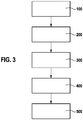
- FIG. 3 schematically illustrates the steps of a method for producing a plug contact after the FIGS. 1 and 2
- a first step 100 is a electrical conductor 2 provided with a plug-in section 3, a connecting portion 4 and a barrier portion 5 arranged therebetween.
- a noble metal for example silver, gold, platinum, palladium, etc.
- the barrier section or the surface of the barrier section 5 is coated with silver.
- a fourth step the now existing silver surface of the barrier section 5 is coated with a second material 9 or a second material 9 is applied to the silver surface of the barrier section 5.
- the second material 9 enters into a chemical bond with the silver coating.
- the surface of the plug-in section 3 is coated with a first material 7a.
- the first coating 7 of the plug-in section 3 is coated with a first material 7a.
- the first material 7a is an organic material containing at least one thiol group.
- the plug contact can be used for example as a male connector or as a pink contact in electrical connectors or harness connectors.
Landscapes
- Connections Effected By Soldering, Adhesion, Or Permanent Deformation (AREA)
- Electroplating Methods And Accessories (AREA)
Applications Claiming Priority (1)
| Application Number | Priority Date | Filing Date | Title |
|---|---|---|---|
| DE102016215879.1A DE102016215879B3 (de) | 2016-08-24 | 2016-08-24 | Steckkontakt, Verfahren zur Herstellung eines solchen sowie elektrisches Steckverbindersystem |
Publications (2)
| Publication Number | Publication Date |
|---|---|
| EP3288120A1 true EP3288120A1 (fr) | 2018-02-28 |
| EP3288120B1 EP3288120B1 (fr) | 2019-03-06 |
Family
ID=59581772
Family Applications (1)
| Application Number | Title | Priority Date | Filing Date |
|---|---|---|---|
| EP17185677.6A Active EP3288120B1 (fr) | 2016-08-24 | 2017-08-10 | Contact enfichable et procédé pour son fabrication |
Country Status (2)
| Country | Link |
|---|---|
| EP (1) | EP3288120B1 (fr) |
| DE (1) | DE102016215879B3 (fr) |
Cited By (1)
| Publication number | Priority date | Publication date | Assignee | Title |
|---|---|---|---|---|
| CN110277668A (zh) * | 2018-03-13 | 2019-09-24 | 泰连德国有限公司 | 用于连接由铜和铝制成的电导体的触头针脚 |
Citations (6)
| Publication number | Priority date | Publication date | Assignee | Title |
|---|---|---|---|---|
| US5139890A (en) * | 1991-09-30 | 1992-08-18 | Olin Corporation | Silver-coated electrical components |
| WO1993006993A1 (fr) * | 1991-09-30 | 1993-04-15 | Olin Corporation | Alliages d'argent destines aux revetements de connecteurs electriques |
| US6627329B1 (en) * | 1998-06-29 | 2003-09-30 | Japan Aviation Electronics Industry | Plated materials and contacts for connectors made by using the same |
| DE10224693A1 (de) | 2002-06-04 | 2003-12-18 | Bosch Gmbh Robert | Verbundwerkstoff zur Herstellung einer elektrischen Kontaktfläche sowie Verfahren zur Erzeugung einer gleitfähigen und korrosionsarmen elektrischen Kontaktoberfläche |
| DE102005047843A1 (de) * | 2005-10-05 | 2007-04-12 | OTB Oberflächentechnik in Berlin GmbH & Co. | Passivierungs- und Schmiermittel für Gold-, Silber- und Kupferoberflächen und Verfahren zu seiner Anwendung |
| WO2007113182A1 (fr) * | 2006-03-31 | 2007-10-11 | Siemens Aktiengesellschaft | procédé pour appliquer des particules de brasure sur des surfaces de contact, particules de brasure convenant dans ce but et composants dotés de surfaces de contact |
Family Cites Families (4)
| Publication number | Priority date | Publication date | Assignee | Title |
|---|---|---|---|---|
| US20050233158A1 (en) * | 2001-07-27 | 2005-10-20 | Tour James M | Molecular electronic interconnects |
| JP4795466B2 (ja) * | 2007-06-29 | 2011-10-19 | 古河電気工業株式会社 | 金属材料、その製造方法、及びそれを用いた電気電子部品 |
| JP5464284B1 (ja) * | 2013-01-10 | 2014-04-09 | 株式会社オートネットワーク技術研究所 | コネクタ端子及びコネクタ端子の製造方法 |
| US8974259B2 (en) * | 2013-03-18 | 2015-03-10 | International Business Machines Corporation | Electrical connectors with encapsulated corrosion inhibitor |
-
2016
- 2016-08-24 DE DE102016215879.1A patent/DE102016215879B3/de not_active Expired - Fee Related
-
2017
- 2017-08-10 EP EP17185677.6A patent/EP3288120B1/fr active Active
Patent Citations (6)
| Publication number | Priority date | Publication date | Assignee | Title |
|---|---|---|---|---|
| US5139890A (en) * | 1991-09-30 | 1992-08-18 | Olin Corporation | Silver-coated electrical components |
| WO1993006993A1 (fr) * | 1991-09-30 | 1993-04-15 | Olin Corporation | Alliages d'argent destines aux revetements de connecteurs electriques |
| US6627329B1 (en) * | 1998-06-29 | 2003-09-30 | Japan Aviation Electronics Industry | Plated materials and contacts for connectors made by using the same |
| DE10224693A1 (de) | 2002-06-04 | 2003-12-18 | Bosch Gmbh Robert | Verbundwerkstoff zur Herstellung einer elektrischen Kontaktfläche sowie Verfahren zur Erzeugung einer gleitfähigen und korrosionsarmen elektrischen Kontaktoberfläche |
| DE102005047843A1 (de) * | 2005-10-05 | 2007-04-12 | OTB Oberflächentechnik in Berlin GmbH & Co. | Passivierungs- und Schmiermittel für Gold-, Silber- und Kupferoberflächen und Verfahren zu seiner Anwendung |
| WO2007113182A1 (fr) * | 2006-03-31 | 2007-10-11 | Siemens Aktiengesellschaft | procédé pour appliquer des particules de brasure sur des surfaces de contact, particules de brasure convenant dans ce but et composants dotés de surfaces de contact |
Non-Patent Citations (1)
| Title |
|---|
| FRANK SCHREIBER: "Structure and Growth of Self-Assembled Monolayers", PROGRESS IN SURFACE SCIENCE, 2000, pages 151 - 256, XP009143276, DOI: doi:10.1016/S0079-6816(00)00024-1 |
Cited By (1)
| Publication number | Priority date | Publication date | Assignee | Title |
|---|---|---|---|---|
| CN110277668A (zh) * | 2018-03-13 | 2019-09-24 | 泰连德国有限公司 | 用于连接由铜和铝制成的电导体的触头针脚 |
Also Published As
| Publication number | Publication date |
|---|---|
| EP3288120B1 (fr) | 2019-03-06 |
| DE102016215879B3 (de) | 2018-02-01 |
Similar Documents
| Publication | Publication Date | Title |
|---|---|---|
| DE102009047043A1 (de) | Lötfreie elektrische Verbindung | |
| DE102009042710A1 (de) | Crimpanschluss und Drahtfixierungsaufbau | |
| EP3066722A1 (fr) | Ensemble de liaison électrique | |
| DE102008061186B4 (de) | Elektronische Kontaktverbindung und Verfahren zur Herstellung einer elektrischen Kontaktverbindung | |
| EP3028344A1 (fr) | Borne de connexion électrique et procédé | |
| DE102014117410B4 (de) | Elektrisches Kontaktelement, Einpressstift, Buchse und Leadframe | |
| DE102008042824B4 (de) | Elektrischer Leiter und Verfahren zur Herstellung eines elektrischen Leiters | |
| EP3288120B1 (fr) | Contact enfichable et procédé pour son fabrication | |
| DE3817706A1 (de) | Klemmfeder | |
| WO2013087268A1 (fr) | Élément de contact et procédé de fabrication dudit élément de contact | |
| WO2019057713A1 (fr) | Contact torsadé pour un composant électrique et procédé de fabrication d'un contact torsadé | |
| DE102008043882A1 (de) | Leiterplattenanordnung zur Verbindung einer Wicklung mit einer Leiterplatte | |
| EP1363362B1 (fr) | Formage des fils électriques d'un câble plat | |
| DE19948037B4 (de) | Elektrisches Steckverbindungselement und -system | |
| DE10301227A1 (de) | Umformen von Leiterenden eines Flachbandkabels | |
| DE202013010545U1 (de) | Elektrisches Kontaktelement | |
| DE102006025661B4 (de) | Kontaktklemme zum Anschließen eines Litzenleiters an einen relativ dünnen Anschlussstift | |
| EP2425492B1 (fr) | Dispositif de connexion électrique | |
| DE102021100774A1 (de) | Elektrische Verbindungseinrichtung und Verfahren zu deren Herstellung | |
| DE102020133899A1 (de) | Steckverbinder und Verfahren zur Herstellung eines Steckverbinders | |
| BE1028912B1 (de) | Steckverbinder und Verfahren zur Herstellung eines Steckverbinders | |
| DE102015214873A1 (de) | Stecker mit Medienbarriere und Verfahren zur Herstellung eines Steckers | |
| DE3245781A1 (de) | Verfahren zum behandeln der oberflaeche eines elektrischen verbindungsorganes und nach dem verfahren hergestelltes verbindungsorgan | |
| DE102012220820A1 (de) | Elektrische Kontaktverbindung, insbesondere für ein Kraftfahrzeug | |
| DE102023106169A1 (de) | Klemmverbinder und steckverbinder mit einem klemmverbinder |
Legal Events
| Date | Code | Title | Description |
|---|---|---|---|
| PUAI | Public reference made under article 153(3) epc to a published international application that has entered the european phase |
Free format text: ORIGINAL CODE: 0009012 |
|
| STAA | Information on the status of an ep patent application or granted ep patent |
Free format text: STATUS: THE APPLICATION HAS BEEN PUBLISHED |
|
| AK | Designated contracting states |
Kind code of ref document: A1 Designated state(s): AL AT BE BG CH CY CZ DE DK EE ES FI FR GB GR HR HU IE IS IT LI LT LU LV MC MK MT NL NO PL PT RO RS SE SI SK SM TR |
|
| AX | Request for extension of the european patent |
Extension state: BA ME |
|
| STAA | Information on the status of an ep patent application or granted ep patent |
Free format text: STATUS: REQUEST FOR EXAMINATION WAS MADE |
|
| 17P | Request for examination filed |
Effective date: 20180828 |
|
| RBV | Designated contracting states (corrected) |
Designated state(s): AL AT BE BG CH CY CZ DE DK EE ES FI FR GB GR HR HU IE IS IT LI LT LU LV MC MK MT NL NO PL PT RO RS SE SI SK SM TR |
|
| REG | Reference to a national code |
Ref country code: DE Ref legal event code: R079 Ref document number: 502017000877 Country of ref document: DE Free format text: PREVIOUS MAIN CLASS: H01R0013030000 Ipc: C23C0022020000 |
|
| GRAP | Despatch of communication of intention to grant a patent |
Free format text: ORIGINAL CODE: EPIDOSNIGR1 |
|
| STAA | Information on the status of an ep patent application or granted ep patent |
Free format text: STATUS: GRANT OF PATENT IS INTENDED |
|
| RIC1 | Information provided on ipc code assigned before grant |
Ipc: H01R 13/04 20060101ALI20181019BHEP Ipc: H01R 13/03 20060101ALI20181019BHEP Ipc: C23C 22/02 20060101AFI20181019BHEP Ipc: H01R 43/16 20060101ALI20181019BHEP |
|
| INTG | Intention to grant announced |
Effective date: 20181122 |
|
| GRAS | Grant fee paid |
Free format text: ORIGINAL CODE: EPIDOSNIGR3 |
|
| GRAA | (expected) grant |
Free format text: ORIGINAL CODE: 0009210 |
|
| STAA | Information on the status of an ep patent application or granted ep patent |
Free format text: STATUS: THE PATENT HAS BEEN GRANTED |
|
| AK | Designated contracting states |
Kind code of ref document: B1 Designated state(s): AL AT BE BG CH CY CZ DE DK EE ES FI FR GB GR HR HU IE IS IT LI LT LU LV MC MK MT NL NO PL PT RO RS SE SI SK SM TR |
|
| REG | Reference to a national code |
Ref country code: GB Ref legal event code: FG4D Free format text: NOT ENGLISH |
|
| REG | Reference to a national code |
Ref country code: CH Ref legal event code: EP Ref country code: AT Ref legal event code: REF Ref document number: 1104668 Country of ref document: AT Kind code of ref document: T Effective date: 20190315 |
|
| REG | Reference to a national code |
Ref country code: DE Ref legal event code: R096 Ref document number: 502017000877 Country of ref document: DE |
|
| REG | Reference to a national code |
Ref country code: IE Ref legal event code: FG4D Free format text: LANGUAGE OF EP DOCUMENT: GERMAN |
|
| REG | Reference to a national code |
Ref country code: NL Ref legal event code: MP Effective date: 20190306 |
|
| REG | Reference to a national code |
Ref country code: LT Ref legal event code: MG4D |
|
| PG25 | Lapsed in a contracting state [announced via postgrant information from national office to epo] |
Ref country code: NO Free format text: LAPSE BECAUSE OF FAILURE TO SUBMIT A TRANSLATION OF THE DESCRIPTION OR TO PAY THE FEE WITHIN THE PRESCRIBED TIME-LIMIT Effective date: 20190606 Ref country code: FI Free format text: LAPSE BECAUSE OF FAILURE TO SUBMIT A TRANSLATION OF THE DESCRIPTION OR TO PAY THE FEE WITHIN THE PRESCRIBED TIME-LIMIT Effective date: 20190306 Ref country code: SE Free format text: LAPSE BECAUSE OF FAILURE TO SUBMIT A TRANSLATION OF THE DESCRIPTION OR TO PAY THE FEE WITHIN THE PRESCRIBED TIME-LIMIT Effective date: 20190306 Ref country code: LT Free format text: LAPSE BECAUSE OF FAILURE TO SUBMIT A TRANSLATION OF THE DESCRIPTION OR TO PAY THE FEE WITHIN THE PRESCRIBED TIME-LIMIT Effective date: 20190306 |
|
| PG25 | Lapsed in a contracting state [announced via postgrant information from national office to epo] |
Ref country code: LV Free format text: LAPSE BECAUSE OF FAILURE TO SUBMIT A TRANSLATION OF THE DESCRIPTION OR TO PAY THE FEE WITHIN THE PRESCRIBED TIME-LIMIT Effective date: 20190306 Ref country code: NL Free format text: LAPSE BECAUSE OF FAILURE TO SUBMIT A TRANSLATION OF THE DESCRIPTION OR TO PAY THE FEE WITHIN THE PRESCRIBED TIME-LIMIT Effective date: 20190306 Ref country code: RS Free format text: LAPSE BECAUSE OF FAILURE TO SUBMIT A TRANSLATION OF THE DESCRIPTION OR TO PAY THE FEE WITHIN THE PRESCRIBED TIME-LIMIT Effective date: 20190306 Ref country code: BG Free format text: LAPSE BECAUSE OF FAILURE TO SUBMIT A TRANSLATION OF THE DESCRIPTION OR TO PAY THE FEE WITHIN THE PRESCRIBED TIME-LIMIT Effective date: 20190606 Ref country code: GR Free format text: LAPSE BECAUSE OF FAILURE TO SUBMIT A TRANSLATION OF THE DESCRIPTION OR TO PAY THE FEE WITHIN THE PRESCRIBED TIME-LIMIT Effective date: 20190607 Ref country code: HR Free format text: LAPSE BECAUSE OF FAILURE TO SUBMIT A TRANSLATION OF THE DESCRIPTION OR TO PAY THE FEE WITHIN THE PRESCRIBED TIME-LIMIT Effective date: 20190306 |
|
| PG25 | Lapsed in a contracting state [announced via postgrant information from national office to epo] |
Ref country code: EE Free format text: LAPSE BECAUSE OF FAILURE TO SUBMIT A TRANSLATION OF THE DESCRIPTION OR TO PAY THE FEE WITHIN THE PRESCRIBED TIME-LIMIT Effective date: 20190306 Ref country code: AL Free format text: LAPSE BECAUSE OF FAILURE TO SUBMIT A TRANSLATION OF THE DESCRIPTION OR TO PAY THE FEE WITHIN THE PRESCRIBED TIME-LIMIT Effective date: 20190306 Ref country code: PT Free format text: LAPSE BECAUSE OF FAILURE TO SUBMIT A TRANSLATION OF THE DESCRIPTION OR TO PAY THE FEE WITHIN THE PRESCRIBED TIME-LIMIT Effective date: 20190706 Ref country code: RO Free format text: LAPSE BECAUSE OF FAILURE TO SUBMIT A TRANSLATION OF THE DESCRIPTION OR TO PAY THE FEE WITHIN THE PRESCRIBED TIME-LIMIT Effective date: 20190306 Ref country code: SK Free format text: LAPSE BECAUSE OF FAILURE TO SUBMIT A TRANSLATION OF THE DESCRIPTION OR TO PAY THE FEE WITHIN THE PRESCRIBED TIME-LIMIT Effective date: 20190306 Ref country code: ES Free format text: LAPSE BECAUSE OF FAILURE TO SUBMIT A TRANSLATION OF THE DESCRIPTION OR TO PAY THE FEE WITHIN THE PRESCRIBED TIME-LIMIT Effective date: 20190306 Ref country code: CZ Free format text: LAPSE BECAUSE OF FAILURE TO SUBMIT A TRANSLATION OF THE DESCRIPTION OR TO PAY THE FEE WITHIN THE PRESCRIBED TIME-LIMIT Effective date: 20190306 |
|
| PG25 | Lapsed in a contracting state [announced via postgrant information from national office to epo] |
Ref country code: SM Free format text: LAPSE BECAUSE OF FAILURE TO SUBMIT A TRANSLATION OF THE DESCRIPTION OR TO PAY THE FEE WITHIN THE PRESCRIBED TIME-LIMIT Effective date: 20190306 Ref country code: PL Free format text: LAPSE BECAUSE OF FAILURE TO SUBMIT A TRANSLATION OF THE DESCRIPTION OR TO PAY THE FEE WITHIN THE PRESCRIBED TIME-LIMIT Effective date: 20190306 |
|
| REG | Reference to a national code |
Ref country code: DE Ref legal event code: R097 Ref document number: 502017000877 Country of ref document: DE |
|
| PG25 | Lapsed in a contracting state [announced via postgrant information from national office to epo] |
Ref country code: IS Free format text: LAPSE BECAUSE OF FAILURE TO SUBMIT A TRANSLATION OF THE DESCRIPTION OR TO PAY THE FEE WITHIN THE PRESCRIBED TIME-LIMIT Effective date: 20190706 |
|
| PLBE | No opposition filed within time limit |
Free format text: ORIGINAL CODE: 0009261 |
|
| STAA | Information on the status of an ep patent application or granted ep patent |
Free format text: STATUS: NO OPPOSITION FILED WITHIN TIME LIMIT |
|
| PG25 | Lapsed in a contracting state [announced via postgrant information from national office to epo] |
Ref country code: DK Free format text: LAPSE BECAUSE OF FAILURE TO SUBMIT A TRANSLATION OF THE DESCRIPTION OR TO PAY THE FEE WITHIN THE PRESCRIBED TIME-LIMIT Effective date: 20190306 |
|
| 26N | No opposition filed |
Effective date: 20191209 |
|
| PG25 | Lapsed in a contracting state [announced via postgrant information from national office to epo] |
Ref country code: SI Free format text: LAPSE BECAUSE OF FAILURE TO SUBMIT A TRANSLATION OF THE DESCRIPTION OR TO PAY THE FEE WITHIN THE PRESCRIBED TIME-LIMIT Effective date: 20190306 |
|
| PG25 | Lapsed in a contracting state [announced via postgrant information from national office to epo] |
Ref country code: TR Free format text: LAPSE BECAUSE OF FAILURE TO SUBMIT A TRANSLATION OF THE DESCRIPTION OR TO PAY THE FEE WITHIN THE PRESCRIBED TIME-LIMIT Effective date: 20190306 |
|
| PG25 | Lapsed in a contracting state [announced via postgrant information from national office to epo] |
Ref country code: LU Free format text: LAPSE BECAUSE OF NON-PAYMENT OF DUE FEES Effective date: 20190810 Ref country code: MC Free format text: LAPSE BECAUSE OF FAILURE TO SUBMIT A TRANSLATION OF THE DESCRIPTION OR TO PAY THE FEE WITHIN THE PRESCRIBED TIME-LIMIT Effective date: 20190306 |
|
| REG | Reference to a national code |
Ref country code: BE Ref legal event code: MM Effective date: 20190831 |
|
| PG25 | Lapsed in a contracting state [announced via postgrant information from national office to epo] |
Ref country code: IE Free format text: LAPSE BECAUSE OF NON-PAYMENT OF DUE FEES Effective date: 20190810 |
|
| PG25 | Lapsed in a contracting state [announced via postgrant information from national office to epo] |
Ref country code: BE Free format text: LAPSE BECAUSE OF NON-PAYMENT OF DUE FEES Effective date: 20190831 |
|
| REG | Reference to a national code |
Ref country code: CH Ref legal event code: PL |
|
| PG25 | Lapsed in a contracting state [announced via postgrant information from national office to epo] |
Ref country code: LI Free format text: LAPSE BECAUSE OF NON-PAYMENT OF DUE FEES Effective date: 20200831 Ref country code: CH Free format text: LAPSE BECAUSE OF NON-PAYMENT OF DUE FEES Effective date: 20200831 |
|
| PG25 | Lapsed in a contracting state [announced via postgrant information from national office to epo] |
Ref country code: CY Free format text: LAPSE BECAUSE OF FAILURE TO SUBMIT A TRANSLATION OF THE DESCRIPTION OR TO PAY THE FEE WITHIN THE PRESCRIBED TIME-LIMIT Effective date: 20190306 |
|
| PG25 | Lapsed in a contracting state [announced via postgrant information from national office to epo] |
Ref country code: HU Free format text: LAPSE BECAUSE OF FAILURE TO SUBMIT A TRANSLATION OF THE DESCRIPTION OR TO PAY THE FEE WITHIN THE PRESCRIBED TIME-LIMIT; INVALID AB INITIO Effective date: 20170810 Ref country code: MT Free format text: LAPSE BECAUSE OF FAILURE TO SUBMIT A TRANSLATION OF THE DESCRIPTION OR TO PAY THE FEE WITHIN THE PRESCRIBED TIME-LIMIT Effective date: 20190306 |
|
| GBPC | Gb: european patent ceased through non-payment of renewal fee |
Effective date: 20210810 |
|
| PG25 | Lapsed in a contracting state [announced via postgrant information from national office to epo] |
Ref country code: MK Free format text: LAPSE BECAUSE OF FAILURE TO SUBMIT A TRANSLATION OF THE DESCRIPTION OR TO PAY THE FEE WITHIN THE PRESCRIBED TIME-LIMIT Effective date: 20190306 |
|
| PG25 | Lapsed in a contracting state [announced via postgrant information from national office to epo] |
Ref country code: GB Free format text: LAPSE BECAUSE OF NON-PAYMENT OF DUE FEES Effective date: 20210810 |
|
| REG | Reference to a national code |
Ref country code: AT Ref legal event code: MM01 Ref document number: 1104668 Country of ref document: AT Kind code of ref document: T Effective date: 20220810 |
|
| PG25 | Lapsed in a contracting state [announced via postgrant information from national office to epo] |
Ref country code: AT Free format text: LAPSE BECAUSE OF NON-PAYMENT OF DUE FEES Effective date: 20220810 |
|
| PGFP | Annual fee paid to national office [announced via postgrant information from national office to epo] |
Ref country code: IT Payment date: 20250829 Year of fee payment: 9 |
|
| PGFP | Annual fee paid to national office [announced via postgrant information from national office to epo] |
Ref country code: FR Payment date: 20250821 Year of fee payment: 9 |
|
| PGFP | Annual fee paid to national office [announced via postgrant information from national office to epo] |
Ref country code: DE Payment date: 20251021 Year of fee payment: 9 |