EP3288420B1 - Tiroir assemblable pour meuble, et procédé d'assemblage dudit tiroir - Google Patents
Tiroir assemblable pour meuble, et procédé d'assemblage dudit tiroir Download PDFInfo
- Publication number
- EP3288420B1 EP3288420B1 EP16719071.9A EP16719071A EP3288420B1 EP 3288420 B1 EP3288420 B1 EP 3288420B1 EP 16719071 A EP16719071 A EP 16719071A EP 3288420 B1 EP3288420 B1 EP 3288420B1
- Authority
- EP
- European Patent Office
- Prior art keywords
- side walls
- coupling
- rear wall
- drawer
- engagement means
- Prior art date
- Legal status (The legal status is an assumption and is not a legal conclusion. Google has not performed a legal analysis and makes no representation as to the accuracy of the status listed.)
- Active
Links
Images






Classifications
-
- A—HUMAN NECESSITIES
- A47—FURNITURE; DOMESTIC ARTICLES OR APPLIANCES; COFFEE MILLS; SPICE MILLS; SUCTION CLEANERS IN GENERAL
- A47B—TABLES; DESKS; OFFICE FURNITURE; CABINETS; DRAWERS; GENERAL DETAILS OF FURNITURE
- A47B88/00—Drawers for tables, cabinets or like furniture; Guides for drawers
- A47B88/90—Constructional details of drawers
- A47B88/944—Drawers characterised by the front panel
- A47B88/95—Drawers characterised by the front panel characterised by connection means for the front panel
-
- A—HUMAN NECESSITIES
- A47—FURNITURE; DOMESTIC ARTICLES OR APPLIANCES; COFFEE MILLS; SPICE MILLS; SUCTION CLEANERS IN GENERAL
- A47B—TABLES; DESKS; OFFICE FURNITURE; CABINETS; DRAWERS; GENERAL DETAILS OF FURNITURE
- A47B88/00—Drawers for tables, cabinets or like furniture; Guides for drawers
- A47B88/90—Constructional details of drawers
- A47B88/941—Drawers being constructed from two or more parts
-
- A—HUMAN NECESSITIES
- A47—FURNITURE; DOMESTIC ARTICLES OR APPLIANCES; COFFEE MILLS; SPICE MILLS; SUCTION CLEANERS IN GENERAL
- A47B—TABLES; DESKS; OFFICE FURNITURE; CABINETS; DRAWERS; GENERAL DETAILS OF FURNITURE
- A47B88/00—Drawers for tables, cabinets or like furniture; Guides for drawers
- A47B88/90—Constructional details of drawers
- A47B2088/902—Corner connectors for drawers
-
- A—HUMAN NECESSITIES
- A47—FURNITURE; DOMESTIC ARTICLES OR APPLIANCES; COFFEE MILLS; SPICE MILLS; SUCTION CLEANERS IN GENERAL
- A47B—TABLES; DESKS; OFFICE FURNITURE; CABINETS; DRAWERS; GENERAL DETAILS OF FURNITURE
- A47B88/00—Drawers for tables, cabinets or like furniture; Guides for drawers
- A47B88/90—Constructional details of drawers
- A47B88/944—Drawers characterised by the front panel
- A47B88/95—Drawers characterised by the front panel characterised by connection means for the front panel
- A47B2088/954—Drawers characterised by the front panel characterised by connection means for the front panel fastening the front panel by a sprung bolt, latch or lock-bolt
-
- A—HUMAN NECESSITIES
- A47—FURNITURE; DOMESTIC ARTICLES OR APPLIANCES; COFFEE MILLS; SPICE MILLS; SUCTION CLEANERS IN GENERAL
- A47B—TABLES; DESKS; OFFICE FURNITURE; CABINETS; DRAWERS; GENERAL DETAILS OF FURNITURE
- A47B2210/00—General construction of drawers, guides and guide devices
- A47B2210/02—Drawers with hollow lateral walls in two parts
Definitions
- the present invention relates to an assemblable drawer for furniture and a method for its assembly.
- front connectors and corner connectors respectively are used, which have parts for coupling which can be inserted in corresponding end openings of the rear and side walls so as to enable a simple and rapid assembly of the parts that make up the drawer.
- connection between the connectors and the walls of the drawer can occur by simple forced coupling of the parts.
- such type of forced coupling or engagement in the event of high stresses that are generated in particular when the drawer is full, can be insufficient to keep the drawer stably assembled.
- the connectors can be provided with tabs or other elastic retention means that can engage by snap action an adapted opening provided on the sides of the side walls and of the rear wall of the drawer.
- the aim of the present invention is to devise an assemblable drawer that has a rear wall and side walls made of metallic material but free from lateral openings, thus eliminating the need to carry out additional machining operations on those walls, so as to not further negatively affect the overall aesthetic appearance of the drawer, while at the same time ensuring a stable assembly of the drawer even in the event of high stresses.
- an object of the present invention is to devise an assemblable drawer for furniture that can be assembled in a simple and rapid manner.
- Another object of the present invention is to devise an assemblable drawer for furniture that is highly reliable, easily and practically implemented and low cost.
- an assemblable drawer for furniture comprising a pair of side walls, a rear wall, a bottom, and a front panel, characterized in that said side walls and said rear wall are provided with end openings which are adapted to allow the coupling of coupling means which in turn are adapted to be locked within said end openings by engagement means which can move for forced or shape coupling of such moveable engagement means in such end openings of such side walls and of such rear wall, wherein said moveable engagement means comprise at least one eccentric engagement element for the forced or shape coupling of said moveable engagement means in said end openings of said rear and side walls, and wherein said moveable engagement means for said corner and front connectors comprise screw means which can engage in said side walls and/or said rear wall.
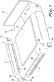
- the drawer according to the invention comprises a pair of side walls 2 and 3, a rear wall 4, a bottom 5 and a front wall 6.
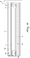
- the side walls are profiled walls made of metallic material that have hollow cross-sections that define end openings or cavities; the possibility is not ruled out however that the walls can instead be made of other materials, for example plastic materials, wood or the like.
- the end openings are provided in the side walls 2, 3 and in the rear wall 4.
- end openings of the side walls are designated by the reference numeral 7
- end openings of the rear wall are designated by the reference numeral 8.
- the side walls 2, 3 and the rear wall 4 have lateral surfaces that are extended according to a respective longitudinal axis, and according to a preferred embodiment of the invention these surfaces have no openings and/or machining; in particular there is no opening or protrusion whose axis extends at right angles to the longitudinal axis of the walls proper.
- coupling means are provided which are constituted by corner elements 10 which are provided at the coupling between the side walls 2 and 3 and the rear wall 4, and front connectors 11 which are provided for coupling the side walls 2 and 3 with the front wall 6.
- the front connectors 11 are engaged by the front coupling means 12 which are arranged to be integral with the wall of the front panel 6.
- the side walls 2 and 3 have grooves 15 which are adapted to allow the coupling of the bottom 5 of the drawer.
- the rear corner connectors 10 are coupled to the corner elements 16 which are inserted in the end cavities 8 of the rear wall 4 and in end cavities 18 of the side walls 2 and 3.
- corner connectors 10 are inserted in the end openings 7 of the side walls 2 and 3 on one side and in a central groove 20 of the rear wall 4 of the drawer according to a preferred embodiment of the invention.
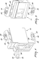
- the drawer In order to lock the coupling means (i.e. the corner elements 10 and the front elements 11), the drawer according to a preferred embodiment of the invention has moveable engagement means which have a control element for example in the form of a slotted head for a screwdriver.
- the moveable engagement means with control element preferably comprise eccentric engagement elements 25 which are rotatably moveable and, for the front connectors 11 and the parts of the corner connectors 10 that are to be inserted in the openings 7 of the side walls 2, 3, are in the form of screw means 25', for example trilobular screws, which when they are tightened, among other things, generate a pull for a firmer coupling of the parts;
- the head 26 is adapted to be rotated in an adapted seat defined in the corner connectors 10 (in this case designated by the reference numeral 27) and in the front connectors 11 (in this case the seat is designated by the reference numeral 28) and is conveniently shaped, for example with radial protrusions or beaks 26', so as to define a stroke limiting stop for the rotation of the engagement means.
- the head 26 is adapted to be rotated in such seats 27 and 28 and with their profile the screw means 25' bite the inner profile of the end openings 7 with regard to the corner connectors 10 and the front connectors 11.
- the moveable engagement means 25 comprise an eccentric engagement surface 30, with threading, which can engage an upper surface 20' of the central groove 20 of the rear wall 4; in this case also the head 26 is conveniently contoured, for example with a radial protrusion or beak 26', to define a stroke limiting stop for the rotation of the engagement means.
- the coupling means 12 of the front panel 6, for example in the form of elements that can be pre-mounted on the front panel 6, are adapted to allow the coupling thereof in the front connectors 11 once these have been coupled to the side walls 2 and 3.
- the coupling elements 12, so as to retain in a longitudinal direction have lateral grooves 12' that extend vertically to engage with internal protrusions 11' of the front connectors 11 by way of a sliding movement from the top downward shown in Figures 8 and 9 ; furthermore the coupling elements 12 have, on a rear side, an elastic retainer tooth 12" which can engage a transverse rib 11" in the front connector 11, so as to firmly retain the parts and allow an uncoupling thereof only if a preset and significant upward stress is applied to the front panel 6.
- the assemblable drawer according to the invention is assembled as follows: firstly the operator arranges the side walls 2, 3, the rear panel or rear wall 4, and the front panel 6, together with the bottom 5 of the drawer. At this point the operator couples the coupling means, in the form of the rear corner connectors 10 and the front connectors 11, within the side walls 2, 3, by tightening the coupling means within such walls with the moveable engagement means 25' and 30.
- the moveable engagement means cause an engagement, with forced and/or shape coupling, in the end openings of the side walls 2, 3 and in the central groove 20 of the rear wall 4.
- the operator applies the bottom panel 5 to the side walls by inserting it in the grooves 15 and finally he/she applies the front panel 6 by coupling the front coupling means 12 in the front connectors 11.
- the drawer according to the present invention fully achieves the set aim and objects, in that it makes it possible to be assembled in a simple and rapid manner, and it does not require lateral openings in the side walls of the drawer, making use instead of end openings that are substantially invisible to the user.
- the materials used may be any according to requirements and to the state of the art.
Landscapes
- Drawers Of Furniture (AREA)
- Furniture Connections (AREA)
Claims (8)
- Tiroir pouvant être assemblé (1) pour meuble, comprenant une paire de parois latérales (2, 3), une paroi arrière (4), un fond (5) et un panneau avant (6), lesdites parois latérales (2, 3) et ladite paroi arrière (4) étant prévues avec des ouvertures d'extrémité (7) qui sont adaptées pour permettre le couplage des moyens de couplage (10, 11) qui sont, à leur tour, adaptés pour être verrouillés dans lesdites ouvertures d'extrémité (7) par des moyens de mise en prise (25, 26, 27, 28) qui peuvent se déplacer pour le couplage forcé ou par complémentarité de forme desdits moyens de mise en prise mobiles dans lesdites ouvertures d'extrémité (7) desdites parois latérales (2, 3) et de ladite paroi arrière (4), dans lequel lesdits moyens de mise en prise mobiles comprennent au moins un élément de mise en prise excentrique (25, 30) pour le couplage forcé ou par complémentarité de forme desdits moyens de mise en prise mobiles dans lesdites ouvertures d'extrémité (7) desdites parois arrière et latérales, caractérisé en ce que lesdits moyens de mise en prise mobiles pour lesdits connecteurs de coin et avant comprennent des moyens de vis (25) qui peuvent se mettre en prise dans lesdites parois latérales (2, 3) et/ou ladite paroi arrière (4).
- Tiroir pouvant être assemblé selon la revendication 1, dans lequel lesdites parois latérales (2, 3) et ladite paroi arrière (4) sont prévues avec des surfaces latérales qui sont étendues selon leur axe d'extension longitudinal respectif, caractérisé en ce que lesdites surfaces latérales des parois latérales (2, 3) et de la paroi arrière (4) n'ont pas d'ouvertures et/ou d'usinage.
- Tiroir pouvant être assemblé selon une ou plusieurs des revendications précédentes, caractérisé en ce que lesdits moyens de couplage (10, 11) comprennent une paire de connecteurs de coin arrière (10) pour le couplage entre lesdites parois latérales (2, 3) et ladite paroi arrière (4) et une paire de connecteurs avant (11) pour le couplage dudit panneau avant (6) avec lesdites parois latérales (2, 3).
- Tiroir pouvant être assemblé selon une ou plusieurs des revendications précédentes, caractérisé en ce que lesdits connecteurs de coin arrière (10) sont prévus avec des sièges (29) pour loger lesdits moyens de mise en prise mobiles.
- Tiroir pouvant être assemblé selon une ou plusieurs des revendications précédentes, caractérisé en ce que lesdits connecteurs avant (11) sont dotés de sièges (28) pour loger lesdits moyens de mise en prise mobiles.
- Tiroir pouvant être assemblé selon une ou plusieurs des revendications précédentes, caractérisé en ce qu'il comprend des moyens de raccordement supplémentaires (16) qui sont adaptés pour permettre le couplage desdites parois latérales (2, 3) avec ladite paroi arrière (4) du tiroir.
- Tiroir pouvant être assemblé selon une ou plusieurs des revendications précédentes, caractérisé en ce qu'il comprend des premiers moyens de couplage avant (12) qui peuvent être fixés audit panneau avant (6) et peuvent être couplés avec lesdits connecteurs avant (11).
- Procédé pour assembler un tiroir pouvant être assemblé comprenant les étapes consistant à :- à partir d'une paire de parois latérales (2, 3), d'une paroi arrière (4), d'un fond (5) et d'un panneau avant (6) d'un tiroir, coupler des moyens de couplage (10, 11) dans des ouvertures d'extrémité (7) desdits parois latérales, pour le couplage desdites parois latérales (2, 3) avec ladite paroi arrière (4) du tiroir ;- verrouiller en place lesdits moyens de couplage au moyen des moyens de mise en prise mobiles (25, 30) qui sont adaptés pour permettre un couplage forcé ou par complémentarité de forme entre lesdits moyens de couplage (10, 11) et lesdites ouvertures d'extrémité (7) desdites parois latérales (2, 3) et de ladite paroi arrière (4) ;- appliquer ledit fond (5) sur lesdites parois latérales (2, 3) ;- fixer le panneau avant (6) sur lesdits moyens de couplage (10, 11) qui sont agencés à l'extrémité desdites parois latérales (2, 3) qui est adaptée pour être dirigée vers ledit panneau avant (6), dans lequel lesdits moyens de mise en prise mobiles comprennent au moins un élément de mise en prise excentrique (25, 30) pour le couplage forcé ou par complémentarité de forme desdits moyens de mise en prise mobiles dans lesdites ouvertures d'extrémité (7) desdites parois arrière et latérales, caractérisé en ce que lesdits moyens de mise en prise mobiles pour lesdits connecteurs de coin et avant comprennent des moyens de vis (25) qui peuvent se mettre en prise dans lesdites parois latérales (2, 3) et/ou ladite paroi arrière (4).
Priority Applications (1)
| Application Number | Priority Date | Filing Date | Title |
|---|---|---|---|
| SI201631021T SI3288420T1 (sl) | 2015-04-30 | 2016-04-27 | Sestavljiv predal za pohištvo in postopek za sestavljanje predala |
Applications Claiming Priority (2)
| Application Number | Priority Date | Filing Date | Title |
|---|---|---|---|
| ITMI20150617 | 2015-04-30 | ||
| PCT/EP2016/059373 WO2016174069A1 (fr) | 2015-04-30 | 2016-04-27 | Tiroir assemblable pour meuble, et procédé d'assemblage dudit tiroir |
Publications (2)
| Publication Number | Publication Date |
|---|---|
| EP3288420A1 EP3288420A1 (fr) | 2018-03-07 |
| EP3288420B1 true EP3288420B1 (fr) | 2020-09-16 |
Family
ID=53719825
Family Applications (1)
| Application Number | Title | Priority Date | Filing Date |
|---|---|---|---|
| EP16719071.9A Active EP3288420B1 (fr) | 2015-04-30 | 2016-04-27 | Tiroir assemblable pour meuble, et procédé d'assemblage dudit tiroir |
Country Status (9)
| Country | Link |
|---|---|
| US (1) | US20180132616A1 (fr) |
| EP (1) | EP3288420B1 (fr) |
| JP (1) | JP6770531B2 (fr) |
| CN (1) | CN107529888B (fr) |
| BR (1) | BR112017021968B8 (fr) |
| ES (1) | ES2834523T3 (fr) |
| SI (1) | SI3288420T1 (fr) |
| TW (1) | TWI690282B (fr) |
| WO (1) | WO2016174069A1 (fr) |
Families Citing this family (5)
| Publication number | Priority date | Publication date | Assignee | Title |
|---|---|---|---|---|
| AU2016259457A1 (en) * | 2016-11-18 | 2018-06-07 | PAYNE, Ian MR | Adjustable mounting system for attaching and aligning drawer fronts |
| US10874213B2 (en) | 2019-01-15 | 2020-12-29 | Tag Hardware Systems Ltd. | Drawer system |
| AT524493B1 (de) * | 2020-12-02 | 2024-10-15 | Blum Gmbh Julius | Verfahren zur manuellen und/oder maschinellen Herstellung einer doppelwandigen Schubladenzarge |
| AT526748B1 (de) * | 2022-11-21 | 2025-04-15 | Blum Gmbh Julius | Möbelbeschlag oder Baubeschlag |
| AT527377B1 (de) * | 2023-07-06 | 2026-04-15 | Blum Gmbh Julius | Schubladenseitenwand für eine Schublade |
Family Cites Families (26)
| Publication number | Priority date | Publication date | Assignee | Title |
|---|---|---|---|---|
| GB1189907A (en) * | 1967-10-16 | 1970-04-29 | Leslie William Llewelly Alston | Improvements in or relating to Drawers for Furniture |
| GB1410377A (en) * | 1972-12-08 | 1975-10-15 | Lb Plastics Ltd | Drawers |
| US4042288A (en) * | 1972-12-08 | 1977-08-16 | L. B. (Plastics) Limited | Extruded plastic panel drawers |
| GB1507498A (en) * | 1975-05-30 | 1978-04-12 | Swish Prod | Structural elements |
| GB1522598A (en) * | 1975-10-23 | 1978-08-23 | Swish Prod | Elements for drawers or like structures |
| GB8710004D0 (en) * | 1987-04-24 | 1987-06-03 | Lb Plastics Ltd | Drawers & drawer components |
| DE3931155A1 (de) * | 1989-09-19 | 1991-03-28 | Lautenschlaeger Kg Karl | Befestigungsanordnung fuer schubladen-frontblenden |
| IT1232630B (it) * | 1989-09-20 | 1992-02-28 | Sisco Sistem S A S Di Paola Ma | Cassetto con sponde in profilato di alluminio estruso. |
| DE3942897A1 (de) * | 1989-12-23 | 1991-06-27 | Grass Ag | Schublade |
| AT398265B (de) * | 1990-01-22 | 1994-11-25 | Blum Gmbh Julius | Befestigungsvorrichtung für die frontblende einer schublade |
| DE9001484U1 (de) * | 1990-02-09 | 1990-04-12 | Schüco International GmbH & Co, 4800 Bielefeld | Schubkasten mit aus Kunststoff- oder Metall-Profilen bestehenden Seitenzargen |
| DE4330919A1 (de) * | 1993-09-11 | 1995-03-16 | Lautenschlaeger Mepla Werke | Eck-Verbindungsbeschlag für Schubladen |
| ES2188603T3 (es) * | 1994-01-17 | 2003-07-01 | Blum Gmbh Julius | Herraje para la fijacion de una pared trasera de un cajon a elementos componentes del cajon. |
| DE19944642A1 (de) * | 1999-09-17 | 2001-03-22 | Hettich Paul Gmbh & Co | Befestigungsvorrichtung |
| DE20007411U1 (de) * | 2000-04-22 | 2001-08-23 | Ninkaplast GmbH, 32108 Bad Salzuflen | Zargenschubkasten mit Eckverbindern |
| JP4322034B2 (ja) * | 2003-03-31 | 2009-08-26 | コクヨ株式会社 | 部材の連結構造 |
| MY140411A (en) * | 2006-07-14 | 2009-12-31 | Harn Marketing Sdn Bhd | Drawer fitting |
| EP1932448B1 (fr) * | 2006-12-15 | 2010-04-14 | Harn Marketing Sdn. Bhd. | Ferrure de coin |
| DE202010007428U1 (de) * | 2010-05-31 | 2011-09-05 | Grass Gmbh | Verbindungsvorrichtung und Schublade mit einer Verbindungsvorrichtung |
| AT510781B1 (de) * | 2010-11-23 | 2014-08-15 | Blum Gmbh Julius | Möbelbeschlag zur frontblendenbefestigung |
| AT511062B1 (de) * | 2011-05-24 | 2012-09-15 | Blum Gmbh Julius | Befestigungsvorrichtung zum befestigen einer frontblende an einer schublade |
| AT511849B1 (de) * | 2011-10-17 | 2013-03-15 | Blum Gmbh Julius | Verbindungsvorrichtung zum verbinden zweier rechtwinklig anzuordnender schubladenwandteile |
| AT512236B1 (de) * | 2011-11-22 | 2015-10-15 | Blum Gmbh Julius | Befestigungsvorrichtung zum befestigen einer frontblende an einer schublade |
| DE202013011421U1 (de) * | 2013-12-20 | 2015-03-23 | Grass Gmbh | Schubladenfrontanbindungselnheit |
| CN107809927A (zh) * | 2015-06-15 | 2018-03-16 | 形橙产品开发公司 | 具有底板、两个侧壁、后壁以及挡板的抽屉 |
| DE202016102168U1 (de) * | 2016-04-25 | 2017-07-26 | Grass Gmbh | Vorrichtung zur Anbringung einer Rückwand an ein bewegbares Möbelteil |
-
2016
- 2016-04-27 EP EP16719071.9A patent/EP3288420B1/fr active Active
- 2016-04-27 US US15/569,810 patent/US20180132616A1/en not_active Abandoned
- 2016-04-27 ES ES16719071T patent/ES2834523T3/es active Active
- 2016-04-27 SI SI201631021T patent/SI3288420T1/sl unknown
- 2016-04-27 WO PCT/EP2016/059373 patent/WO2016174069A1/fr not_active Ceased
- 2016-04-27 CN CN201680024721.3A patent/CN107529888B/zh active Active
- 2016-04-27 JP JP2017556882A patent/JP6770531B2/ja active Active
- 2016-04-27 BR BR112017021968A patent/BR112017021968B8/pt active IP Right Grant
- 2016-04-28 TW TW105113249A patent/TWI690282B/zh active
Non-Patent Citations (1)
| Title |
|---|
| None * |
Also Published As
| Publication number | Publication date |
|---|---|
| SI3288420T1 (sl) | 2021-01-29 |
| BR112017021968B1 (pt) | 2021-03-23 |
| CN107529888B (zh) | 2020-02-21 |
| EP3288420A1 (fr) | 2018-03-07 |
| JP2018520716A (ja) | 2018-08-02 |
| CN107529888A (zh) | 2018-01-02 |
| BR112017021968B8 (pt) | 2021-04-20 |
| TWI690282B (zh) | 2020-04-11 |
| TW201707613A (zh) | 2017-03-01 |
| BR112017021968A2 (pt) | 2018-07-10 |
| JP6770531B2 (ja) | 2020-10-14 |
| ES2834523T3 (es) | 2021-06-17 |
| WO2016174069A1 (fr) | 2016-11-03 |
| US20180132616A1 (en) | 2018-05-17 |
Similar Documents
| Publication | Publication Date | Title |
|---|---|---|
| US12313105B2 (en) | Piece of furniture | |
| US20180132616A1 (en) | Assemblable drawer for furniture and method for assembling the drawer | |
| US10669716B2 (en) | Panels comprising a mechanical locking device and an assembled product comprising the panels | |
| CN108138825B (zh) | 用于家具和家居用品的部件的具有广泛可及性的接合装置 | |
| CN109196235A (zh) | 用于将家具及其他装饰物品中的第一面板与第二面板连接的紧凑型连接件 | |
| CN109154320B (zh) | 用于家具和家居用品的底部件的具有前部致动的隐藏式接合系统 | |
| EP3919760B1 (fr) | Assemblage destiné au raccord solide d'un premier et d'un second panneau de mobilier et d'autres articles d'ameublement | |
| US20120133253A1 (en) | Furniture kit | |
| KR20190063351A (ko) | 틀 프레임용 모서리 연결구의 프레임 고정장치 | |
| US20200085192A1 (en) | Multifunctional furniture module | |
| EP3153717B1 (fr) | Dispositif d'assemblage double réglable en hauteur pour panneau centrale est des pièces de meuble et des articles d'ameublement | |
| KR200460995Y1 (ko) | 억지 끼워 맞춤 결합식 도어패널 손잡이 | |
| KR200491824Y1 (ko) | 수납장용 랙 구조 | |
| EP3153719B1 (fr) | Combination d'un dispositif d'assemblage double et de trois panneaux pour panneau centrale de meuble et meuble correspondant | |
| JP2006204500A (ja) | 取手 | |
| KR20190103713A (ko) | 틀 프레임용 모서리 연결구의 프레임 고정장치 |
Legal Events
| Date | Code | Title | Description |
|---|---|---|---|
| STAA | Information on the status of an ep patent application or granted ep patent |
Free format text: STATUS: THE INTERNATIONAL PUBLICATION HAS BEEN MADE |
|
| PUAI | Public reference made under article 153(3) epc to a published international application that has entered the european phase |
Free format text: ORIGINAL CODE: 0009012 |
|
| STAA | Information on the status of an ep patent application or granted ep patent |
Free format text: STATUS: REQUEST FOR EXAMINATION WAS MADE |
|
| 17P | Request for examination filed |
Effective date: 20171123 |
|
| AK | Designated contracting states |
Kind code of ref document: A1 Designated state(s): AL AT BE BG CH CY CZ DE DK EE ES FI FR GB GR HR HU IE IS IT LI LT LU LV MC MK MT NL NO PL PT RO RS SE SI SK SM TR |
|
| AX | Request for extension of the european patent |
Extension state: BA ME |
|
| DAV | Request for validation of the european patent (deleted) | ||
| DAX | Request for extension of the european patent (deleted) | ||
| STAA | Information on the status of an ep patent application or granted ep patent |
Free format text: STATUS: EXAMINATION IS IN PROGRESS |
|
| 17Q | First examination report despatched |
Effective date: 20181127 |
|
| GRAP | Despatch of communication of intention to grant a patent |
Free format text: ORIGINAL CODE: EPIDOSNIGR1 |
|
| STAA | Information on the status of an ep patent application or granted ep patent |
Free format text: STATUS: GRANT OF PATENT IS INTENDED |
|
| INTG | Intention to grant announced |
Effective date: 20200325 |
|
| GRAS | Grant fee paid |
Free format text: ORIGINAL CODE: EPIDOSNIGR3 |
|
| GRAA | (expected) grant |
Free format text: ORIGINAL CODE: 0009210 |
|
| STAA | Information on the status of an ep patent application or granted ep patent |
Free format text: STATUS: THE PATENT HAS BEEN GRANTED |
|
| AK | Designated contracting states |
Kind code of ref document: B1 Designated state(s): AL AT BE BG CH CY CZ DE DK EE ES FI FR GB GR HR HU IE IS IT LI LT LU LV MC MK MT NL NO PL PT RO RS SE SI SK SM TR |
|
| REG | Reference to a national code |
Ref country code: GB Ref legal event code: FG4D |
|
| REG | Reference to a national code |
Ref country code: CH Ref legal event code: EP |
|
| REG | Reference to a national code |
Ref country code: DE Ref legal event code: R096 Ref document number: 602016044083 Country of ref document: DE |
|
| REG | Reference to a national code |
Ref country code: IE Ref legal event code: FG4D |
|
| REG | Reference to a national code |
Ref country code: AT Ref legal event code: REF Ref document number: 1313326 Country of ref document: AT Kind code of ref document: T Effective date: 20201015 |
|
| PG25 | Lapsed in a contracting state [announced via postgrant information from national office to epo] |
Ref country code: HR Free format text: LAPSE BECAUSE OF FAILURE TO SUBMIT A TRANSLATION OF THE DESCRIPTION OR TO PAY THE FEE WITHIN THE PRESCRIBED TIME-LIMIT Effective date: 20200916 Ref country code: BG Free format text: LAPSE BECAUSE OF FAILURE TO SUBMIT A TRANSLATION OF THE DESCRIPTION OR TO PAY THE FEE WITHIN THE PRESCRIBED TIME-LIMIT Effective date: 20201216 Ref country code: GR Free format text: LAPSE BECAUSE OF FAILURE TO SUBMIT A TRANSLATION OF THE DESCRIPTION OR TO PAY THE FEE WITHIN THE PRESCRIBED TIME-LIMIT Effective date: 20201217 Ref country code: SE Free format text: LAPSE BECAUSE OF FAILURE TO SUBMIT A TRANSLATION OF THE DESCRIPTION OR TO PAY THE FEE WITHIN THE PRESCRIBED TIME-LIMIT Effective date: 20200916 Ref country code: NO Free format text: LAPSE BECAUSE OF FAILURE TO SUBMIT A TRANSLATION OF THE DESCRIPTION OR TO PAY THE FEE WITHIN THE PRESCRIBED TIME-LIMIT Effective date: 20201216 Ref country code: FI Free format text: LAPSE BECAUSE OF FAILURE TO SUBMIT A TRANSLATION OF THE DESCRIPTION OR TO PAY THE FEE WITHIN THE PRESCRIBED TIME-LIMIT Effective date: 20200916 |
|
| REG | Reference to a national code |
Ref country code: NL Ref legal event code: MP Effective date: 20200916 |
|
| PG25 | Lapsed in a contracting state [announced via postgrant information from national office to epo] |
Ref country code: RS Free format text: LAPSE BECAUSE OF FAILURE TO SUBMIT A TRANSLATION OF THE DESCRIPTION OR TO PAY THE FEE WITHIN THE PRESCRIBED TIME-LIMIT Effective date: 20200916 Ref country code: LV Free format text: LAPSE BECAUSE OF FAILURE TO SUBMIT A TRANSLATION OF THE DESCRIPTION OR TO PAY THE FEE WITHIN THE PRESCRIBED TIME-LIMIT Effective date: 20200916 |
|
| REG | Reference to a national code |
Ref country code: LT Ref legal event code: MG4D |
|
| PG25 | Lapsed in a contracting state [announced via postgrant information from national office to epo] |
Ref country code: LT Free format text: LAPSE BECAUSE OF FAILURE TO SUBMIT A TRANSLATION OF THE DESCRIPTION OR TO PAY THE FEE WITHIN THE PRESCRIBED TIME-LIMIT Effective date: 20200916 Ref country code: SM Free format text: LAPSE BECAUSE OF FAILURE TO SUBMIT A TRANSLATION OF THE DESCRIPTION OR TO PAY THE FEE WITHIN THE PRESCRIBED TIME-LIMIT Effective date: 20200916 Ref country code: PT Free format text: LAPSE BECAUSE OF FAILURE TO SUBMIT A TRANSLATION OF THE DESCRIPTION OR TO PAY THE FEE WITHIN THE PRESCRIBED TIME-LIMIT Effective date: 20210118 Ref country code: RO Free format text: LAPSE BECAUSE OF FAILURE TO SUBMIT A TRANSLATION OF THE DESCRIPTION OR TO PAY THE FEE WITHIN THE PRESCRIBED TIME-LIMIT Effective date: 20200916 Ref country code: EE Free format text: LAPSE BECAUSE OF FAILURE TO SUBMIT A TRANSLATION OF THE DESCRIPTION OR TO PAY THE FEE WITHIN THE PRESCRIBED TIME-LIMIT Effective date: 20200916 |
|
| PG25 | Lapsed in a contracting state [announced via postgrant information from national office to epo] |
Ref country code: IS Free format text: LAPSE BECAUSE OF FAILURE TO SUBMIT A TRANSLATION OF THE DESCRIPTION OR TO PAY THE FEE WITHIN THE PRESCRIBED TIME-LIMIT Effective date: 20210116 Ref country code: AL Free format text: LAPSE BECAUSE OF FAILURE TO SUBMIT A TRANSLATION OF THE DESCRIPTION OR TO PAY THE FEE WITHIN THE PRESCRIBED TIME-LIMIT Effective date: 20200916 |
|
| REG | Reference to a national code |
Ref country code: ES Ref legal event code: FG2A Ref document number: 2834523 Country of ref document: ES Kind code of ref document: T3 Effective date: 20210617 Ref country code: DE Ref legal event code: R097 Ref document number: 602016044083 Country of ref document: DE |
|
| PG25 | Lapsed in a contracting state [announced via postgrant information from national office to epo] |
Ref country code: SK Free format text: LAPSE BECAUSE OF FAILURE TO SUBMIT A TRANSLATION OF THE DESCRIPTION OR TO PAY THE FEE WITHIN THE PRESCRIBED TIME-LIMIT Effective date: 20200916 |
|
| REG | Reference to a national code |
Ref country code: AT Ref legal event code: UEP Ref document number: 1313326 Country of ref document: AT Kind code of ref document: T Effective date: 20200916 |
|
| PLBE | No opposition filed within time limit |
Free format text: ORIGINAL CODE: 0009261 |
|
| STAA | Information on the status of an ep patent application or granted ep patent |
Free format text: STATUS: NO OPPOSITION FILED WITHIN TIME LIMIT |
|
| 26N | No opposition filed |
Effective date: 20210617 |
|
| PG25 | Lapsed in a contracting state [announced via postgrant information from national office to epo] |
Ref country code: DK Free format text: LAPSE BECAUSE OF FAILURE TO SUBMIT A TRANSLATION OF THE DESCRIPTION OR TO PAY THE FEE WITHIN THE PRESCRIBED TIME-LIMIT Effective date: 20200916 |
|
| PG25 | Lapsed in a contracting state [announced via postgrant information from national office to epo] |
Ref country code: MC Free format text: LAPSE BECAUSE OF FAILURE TO SUBMIT A TRANSLATION OF THE DESCRIPTION OR TO PAY THE FEE WITHIN THE PRESCRIBED TIME-LIMIT Effective date: 20200916 |
|
| GBPC | Gb: european patent ceased through non-payment of renewal fee |
Effective date: 20210427 |
|
| PG25 | Lapsed in a contracting state [announced via postgrant information from national office to epo] |
Ref country code: LU Free format text: LAPSE BECAUSE OF NON-PAYMENT OF DUE FEES Effective date: 20210427 |
|
| REG | Reference to a national code |
Ref country code: BE Ref legal event code: MM Effective date: 20210430 |
|
| PG25 | Lapsed in a contracting state [announced via postgrant information from national office to epo] |
Ref country code: LI Free format text: LAPSE BECAUSE OF NON-PAYMENT OF DUE FEES Effective date: 20210430 Ref country code: CH Free format text: LAPSE BECAUSE OF NON-PAYMENT OF DUE FEES Effective date: 20210430 Ref country code: GB Free format text: LAPSE BECAUSE OF NON-PAYMENT OF DUE FEES Effective date: 20210427 Ref country code: FR Free format text: LAPSE BECAUSE OF NON-PAYMENT OF DUE FEES Effective date: 20210430 |
|
| PG25 | Lapsed in a contracting state [announced via postgrant information from national office to epo] |
Ref country code: IE Free format text: LAPSE BECAUSE OF NON-PAYMENT OF DUE FEES Effective date: 20210427 |
|
| PG25 | Lapsed in a contracting state [announced via postgrant information from national office to epo] |
Ref country code: IS Free format text: LAPSE BECAUSE OF FAILURE TO SUBMIT A TRANSLATION OF THE DESCRIPTION OR TO PAY THE FEE WITHIN THE PRESCRIBED TIME-LIMIT Effective date: 20210116 |
|
| PG25 | Lapsed in a contracting state [announced via postgrant information from national office to epo] |
Ref country code: BE Free format text: LAPSE BECAUSE OF NON-PAYMENT OF DUE FEES Effective date: 20210430 |
|
| PG25 | Lapsed in a contracting state [announced via postgrant information from national office to epo] |
Ref country code: HU Free format text: LAPSE BECAUSE OF FAILURE TO SUBMIT A TRANSLATION OF THE DESCRIPTION OR TO PAY THE FEE WITHIN THE PRESCRIBED TIME-LIMIT; INVALID AB INITIO Effective date: 20160427 |
|
| P01 | Opt-out of the competence of the unified patent court (upc) registered |
Effective date: 20230515 |
|
| PG25 | Lapsed in a contracting state [announced via postgrant information from national office to epo] |
Ref country code: NL Free format text: LAPSE BECAUSE OF NON-PAYMENT OF DUE FEES Effective date: 20200923 Ref country code: CY Free format text: LAPSE BECAUSE OF FAILURE TO SUBMIT A TRANSLATION OF THE DESCRIPTION OR TO PAY THE FEE WITHIN THE PRESCRIBED TIME-LIMIT Effective date: 20200916 |
|
| PG25 | Lapsed in a contracting state [announced via postgrant information from national office to epo] |
Ref country code: MK Free format text: LAPSE BECAUSE OF FAILURE TO SUBMIT A TRANSLATION OF THE DESCRIPTION OR TO PAY THE FEE WITHIN THE PRESCRIBED TIME-LIMIT Effective date: 20200916 |
|
| PG25 | Lapsed in a contracting state [announced via postgrant information from national office to epo] |
Ref country code: MT Free format text: LAPSE BECAUSE OF FAILURE TO SUBMIT A TRANSLATION OF THE DESCRIPTION OR TO PAY THE FEE WITHIN THE PRESCRIBED TIME-LIMIT Effective date: 20200916 |
|
| PGFP | Annual fee paid to national office [announced via postgrant information from national office to epo] |
Ref country code: DE Payment date: 20250429 Year of fee payment: 10 |
|
| PGFP | Annual fee paid to national office [announced via postgrant information from national office to epo] |
Ref country code: ES Payment date: 20250505 Year of fee payment: 10 |
|
| PGFP | Annual fee paid to national office [announced via postgrant information from national office to epo] |
Ref country code: IT Payment date: 20250422 Year of fee payment: 10 |
|
| PGFP | Annual fee paid to national office [announced via postgrant information from national office to epo] |
Ref country code: AT Payment date: 20250402 Year of fee payment: 10 |
|
| PGFP | Annual fee paid to national office [announced via postgrant information from national office to epo] |
Ref country code: TR Payment date: 20250418 Year of fee payment: 10 |
|
| PGFP | Annual fee paid to national office [announced via postgrant information from national office to epo] |
Ref country code: CZ Payment date: 20250408 Year of fee payment: 10 |
|
| PGFP | Annual fee paid to national office [announced via postgrant information from national office to epo] |
Ref country code: PL Payment date: 20260331 Year of fee payment: 11 |
|
| PGFP | Annual fee paid to national office [announced via postgrant information from national office to epo] |
Ref country code: SI Payment date: 20260330 Year of fee payment: 11 |