EP3288465B1 - Vorrichtungsinterne fusion von optischer und inerter positionsverfolgung von ultraschallsonden - Google Patents
Vorrichtungsinterne fusion von optischer und inerter positionsverfolgung von ultraschallsonden Download PDFInfo
- Publication number
- EP3288465B1 EP3288465B1 EP16720692.9A EP16720692A EP3288465B1 EP 3288465 B1 EP3288465 B1 EP 3288465B1 EP 16720692 A EP16720692 A EP 16720692A EP 3288465 B1 EP3288465 B1 EP 3288465B1
- Authority
- EP
- European Patent Office
- Prior art keywords
- processor
- image data
- subject
- optical
- sensors
- Prior art date
- Legal status (The legal status is an assumption and is not a legal conclusion. Google has not performed a legal analysis and makes no representation as to the accuracy of the status listed.)
- Not-in-force
Links
- 230000003287 optical effect Effects 0.000 title claims description 83
- 239000000523 sample Substances 0.000 title claims description 69
- 238000002604 ultrasonography Methods 0.000 title claims description 69
- 230000004927 fusion Effects 0.000 title description 2
- 238000000034 method Methods 0.000 claims description 74
- 238000003384 imaging method Methods 0.000 claims description 40
- 230000008569 process Effects 0.000 claims description 20
- 230000033001 locomotion Effects 0.000 claims description 11
- 230000001575 pathological effect Effects 0.000 claims description 8
- 230000000007 visual effect Effects 0.000 claims description 8
- 238000009825 accumulation Methods 0.000 claims description 6
- 238000004891 communication Methods 0.000 claims description 6
- 238000012545 processing Methods 0.000 claims description 6
- 230000004807 localization Effects 0.000 claims description 5
- 238000013507 mapping Methods 0.000 claims description 5
- 238000003860 storage Methods 0.000 description 6
- 238000012285 ultrasound imaging Methods 0.000 description 6
- 238000010586 diagram Methods 0.000 description 5
- 238000004590 computer program Methods 0.000 description 4
- 230000008901 benefit Effects 0.000 description 3
- 210000003484 anatomy Anatomy 0.000 description 2
- 238000003745 diagnosis Methods 0.000 description 2
- 238000005516 engineering process Methods 0.000 description 2
- 230000010354 integration Effects 0.000 description 2
- 238000004519 manufacturing process Methods 0.000 description 2
- 239000000463 material Substances 0.000 description 2
- 238000005259 measurement Methods 0.000 description 2
- 238000002360 preparation method Methods 0.000 description 2
- 238000012552 review Methods 0.000 description 2
- 238000000926 separation method Methods 0.000 description 2
- 230000001427 coherent effect Effects 0.000 description 1
- 230000001419 dependent effect Effects 0.000 description 1
- 238000013461 design Methods 0.000 description 1
- 238000002059 diagnostic imaging Methods 0.000 description 1
- 230000007613 environmental effect Effects 0.000 description 1
- 238000012986 modification Methods 0.000 description 1
- 230000004048 modification Effects 0.000 description 1
- 230000002123 temporal effect Effects 0.000 description 1
- 238000012549 training Methods 0.000 description 1
- 238000012546 transfer Methods 0.000 description 1
Images




Classifications
-
- A—HUMAN NECESSITIES
- A61—MEDICAL OR VETERINARY SCIENCE; HYGIENE
- A61B—DIAGNOSIS; SURGERY; IDENTIFICATION
- A61B8/00—Diagnosis using ultrasonic, sonic or infrasonic waves
- A61B8/42—Details of probe positioning or probe attachment to the patient
- A61B8/4245—Details of probe positioning or probe attachment to the patient involving determining the position of the probe, e.g. with respect to an external reference frame or to the patient
-
- A—HUMAN NECESSITIES
- A61—MEDICAL OR VETERINARY SCIENCE; HYGIENE
- A61B—DIAGNOSIS; SURGERY; IDENTIFICATION
- A61B8/00—Diagnosis using ultrasonic, sonic or infrasonic waves
- A61B8/42—Details of probe positioning or probe attachment to the patient
- A61B8/4245—Details of probe positioning or probe attachment to the patient involving determining the position of the probe, e.g. with respect to an external reference frame or to the patient
- A61B8/4254—Details of probe positioning or probe attachment to the patient involving determining the position of the probe, e.g. with respect to an external reference frame or to the patient using sensors mounted on the probe
-
- A—HUMAN NECESSITIES
- A61—MEDICAL OR VETERINARY SCIENCE; HYGIENE
- A61B—DIAGNOSIS; SURGERY; IDENTIFICATION
- A61B8/00—Diagnosis using ultrasonic, sonic or infrasonic waves
- A61B8/44—Constructional features of the ultrasonic, sonic or infrasonic diagnostic device
- A61B8/4427—Device being portable or laptop-like
-
- A—HUMAN NECESSITIES
- A61—MEDICAL OR VETERINARY SCIENCE; HYGIENE
- A61B—DIAGNOSIS; SURGERY; IDENTIFICATION
- A61B8/00—Diagnosis using ultrasonic, sonic or infrasonic waves
- A61B8/46—Ultrasonic, sonic or infrasonic diagnostic devices with special arrangements for interfacing with the operator or the patient
- A61B8/467—Ultrasonic, sonic or infrasonic diagnostic devices with special arrangements for interfacing with the operator or the patient characterised by special input means
-
- A—HUMAN NECESSITIES
- A61—MEDICAL OR VETERINARY SCIENCE; HYGIENE
- A61B—DIAGNOSIS; SURGERY; IDENTIFICATION
- A61B8/00—Diagnosis using ultrasonic, sonic or infrasonic waves
- A61B8/48—Diagnostic techniques
- A61B8/483—Diagnostic techniques involving the acquisition of a 3D volume of data
-
- A—HUMAN NECESSITIES
- A61—MEDICAL OR VETERINARY SCIENCE; HYGIENE
- A61B—DIAGNOSIS; SURGERY; IDENTIFICATION
- A61B8/00—Diagnosis using ultrasonic, sonic or infrasonic waves
- A61B8/52—Devices using data or image processing specially adapted for diagnosis using ultrasonic, sonic or infrasonic waves
- A61B8/5215—Devices using data or image processing specially adapted for diagnosis using ultrasonic, sonic or infrasonic waves involving processing of medical diagnostic data
- A61B8/5238—Devices using data or image processing specially adapted for diagnosis using ultrasonic, sonic or infrasonic waves involving processing of medical diagnostic data for combining image data of patient, e.g. merging several images from different acquisition modes into one image
- A61B8/5246—Devices using data or image processing specially adapted for diagnosis using ultrasonic, sonic or infrasonic waves involving processing of medical diagnostic data for combining image data of patient, e.g. merging several images from different acquisition modes into one image combining images from the same or different imaging techniques, e.g. color Doppler and B-mode
- A61B8/5253—Devices using data or image processing specially adapted for diagnosis using ultrasonic, sonic or infrasonic waves involving processing of medical diagnostic data for combining image data of patient, e.g. merging several images from different acquisition modes into one image combining images from the same or different imaging techniques, e.g. color Doppler and B-mode combining overlapping images, e.g. spatial compounding
-
- A—HUMAN NECESSITIES
- A61—MEDICAL OR VETERINARY SCIENCE; HYGIENE
- A61B—DIAGNOSIS; SURGERY; IDENTIFICATION
- A61B8/00—Diagnosis using ultrasonic, sonic or infrasonic waves
- A61B8/52—Devices using data or image processing specially adapted for diagnosis using ultrasonic, sonic or infrasonic waves
- A61B8/5269—Devices using data or image processing specially adapted for diagnosis using ultrasonic, sonic or infrasonic waves involving detection or reduction of artifacts
-
- A—HUMAN NECESSITIES
- A61—MEDICAL OR VETERINARY SCIENCE; HYGIENE
- A61B—DIAGNOSIS; SURGERY; IDENTIFICATION
- A61B8/00—Diagnosis using ultrasonic, sonic or infrasonic waves
- A61B8/52—Devices using data or image processing specially adapted for diagnosis using ultrasonic, sonic or infrasonic waves
- A61B8/5269—Devices using data or image processing specially adapted for diagnosis using ultrasonic, sonic or infrasonic waves involving detection or reduction of artifacts
- A61B8/5276—Devices using data or image processing specially adapted for diagnosis using ultrasonic, sonic or infrasonic waves involving detection or reduction of artifacts due to motion
-
- A—HUMAN NECESSITIES
- A61—MEDICAL OR VETERINARY SCIENCE; HYGIENE
- A61B—DIAGNOSIS; SURGERY; IDENTIFICATION
- A61B8/00—Diagnosis using ultrasonic, sonic or infrasonic waves
- A61B8/54—Control of the diagnostic device
-
- A—HUMAN NECESSITIES
- A61—MEDICAL OR VETERINARY SCIENCE; HYGIENE
- A61B—DIAGNOSIS; SURGERY; IDENTIFICATION
- A61B8/00—Diagnosis using ultrasonic, sonic or infrasonic waves
- A61B8/58—Testing, adjusting or calibrating the diagnostic device
-
- G—PHYSICS
- G01—MEASURING; TESTING
- G01C—MEASURING DISTANCES, LEVELS OR BEARINGS; SURVEYING; NAVIGATION; GYROSCOPIC INSTRUMENTS; PHOTOGRAMMETRY OR VIDEOGRAMMETRY
- G01C21/00—Navigation; Navigational instruments not provided for in groups G01C1/00 - G01C19/00
- G01C21/10—Navigation; Navigational instruments not provided for in groups G01C1/00 - G01C19/00 by using measurements of speed or acceleration
- G01C21/12—Navigation; Navigational instruments not provided for in groups G01C1/00 - G01C19/00 by using measurements of speed or acceleration executed aboard the object being navigated; Dead reckoning
- G01C21/16—Navigation; Navigational instruments not provided for in groups G01C1/00 - G01C19/00 by using measurements of speed or acceleration executed aboard the object being navigated; Dead reckoning by integrating acceleration or speed, i.e. inertial navigation
- G01C21/165—Navigation; Navigational instruments not provided for in groups G01C1/00 - G01C19/00 by using measurements of speed or acceleration executed aboard the object being navigated; Dead reckoning by integrating acceleration or speed, i.e. inertial navigation combined with non-inertial navigation instruments
- G01C21/1652—Navigation; Navigational instruments not provided for in groups G01C1/00 - G01C19/00 by using measurements of speed or acceleration executed aboard the object being navigated; Dead reckoning by integrating acceleration or speed, i.e. inertial navigation combined with non-inertial navigation instruments with ranging devices, e.g. LIDAR or RADAR
-
- G—PHYSICS
- G01—MEASURING; TESTING
- G01C—MEASURING DISTANCES, LEVELS OR BEARINGS; SURVEYING; NAVIGATION; GYROSCOPIC INSTRUMENTS; PHOTOGRAMMETRY OR VIDEOGRAMMETRY
- G01C21/00—Navigation; Navigational instruments not provided for in groups G01C1/00 - G01C19/00
- G01C21/10—Navigation; Navigational instruments not provided for in groups G01C1/00 - G01C19/00 by using measurements of speed or acceleration
- G01C21/12—Navigation; Navigational instruments not provided for in groups G01C1/00 - G01C19/00 by using measurements of speed or acceleration executed aboard the object being navigated; Dead reckoning
- G01C21/16—Navigation; Navigational instruments not provided for in groups G01C1/00 - G01C19/00 by using measurements of speed or acceleration executed aboard the object being navigated; Dead reckoning by integrating acceleration or speed, i.e. inertial navigation
- G01C21/165—Navigation; Navigational instruments not provided for in groups G01C1/00 - G01C19/00 by using measurements of speed or acceleration executed aboard the object being navigated; Dead reckoning by integrating acceleration or speed, i.e. inertial navigation combined with non-inertial navigation instruments
- G01C21/1656—Navigation; Navigational instruments not provided for in groups G01C1/00 - G01C19/00 by using measurements of speed or acceleration executed aboard the object being navigated; Dead reckoning by integrating acceleration or speed, i.e. inertial navigation combined with non-inertial navigation instruments with passive imaging devices, e.g. cameras
-
- G—PHYSICS
- G16—INFORMATION AND COMMUNICATION TECHNOLOGY [ICT] SPECIALLY ADAPTED FOR SPECIFIC APPLICATION FIELDS
- G16Z—INFORMATION AND COMMUNICATION TECHNOLOGY [ICT] SPECIALLY ADAPTED FOR SPECIFIC APPLICATION FIELDS, NOT OTHERWISE PROVIDED FOR
- G16Z99/00—Subject matter not provided for in other main groups of this subclass
-
- A—HUMAN NECESSITIES
- A61—MEDICAL OR VETERINARY SCIENCE; HYGIENE
- A61B—DIAGNOSIS; SURGERY; IDENTIFICATION
- A61B8/00—Diagnosis using ultrasonic, sonic or infrasonic waves
- A61B8/44—Constructional features of the ultrasonic, sonic or infrasonic diagnostic device
- A61B8/4444—Constructional features of the ultrasonic, sonic or infrasonic diagnostic device related to the probe
-
- A—HUMAN NECESSITIES
- A61—MEDICAL OR VETERINARY SCIENCE; HYGIENE
- A61B—DIAGNOSIS; SURGERY; IDENTIFICATION
- A61B8/00—Diagnosis using ultrasonic, sonic or infrasonic waves
- A61B8/44—Constructional features of the ultrasonic, sonic or infrasonic diagnostic device
- A61B8/4477—Constructional features of the ultrasonic, sonic or infrasonic diagnostic device using several separate ultrasound transducers or probes
-
- A—HUMAN NECESSITIES
- A61—MEDICAL OR VETERINARY SCIENCE; HYGIENE
- A61B—DIAGNOSIS; SURGERY; IDENTIFICATION
- A61B8/00—Diagnosis using ultrasonic, sonic or infrasonic waves
- A61B8/44—Constructional features of the ultrasonic, sonic or infrasonic diagnostic device
- A61B8/4483—Constructional features of the ultrasonic, sonic or infrasonic diagnostic device characterised by features of the ultrasound transducer
-
- A—HUMAN NECESSITIES
- A61—MEDICAL OR VETERINARY SCIENCE; HYGIENE
- A61B—DIAGNOSIS; SURGERY; IDENTIFICATION
- A61B8/00—Diagnosis using ultrasonic, sonic or infrasonic waves
- A61B8/52—Devices using data or image processing specially adapted for diagnosis using ultrasonic, sonic or infrasonic waves
- A61B8/5215—Devices using data or image processing specially adapted for diagnosis using ultrasonic, sonic or infrasonic waves involving processing of medical diagnostic data
- A61B8/5223—Devices using data or image processing specially adapted for diagnosis using ultrasonic, sonic or infrasonic waves involving processing of medical diagnostic data for extracting a diagnostic or physiological parameter from medical diagnostic data
-
- A—HUMAN NECESSITIES
- A61—MEDICAL OR VETERINARY SCIENCE; HYGIENE
- A61B—DIAGNOSIS; SURGERY; IDENTIFICATION
- A61B8/00—Diagnosis using ultrasonic, sonic or infrasonic waves
- A61B8/52—Devices using data or image processing specially adapted for diagnosis using ultrasonic, sonic or infrasonic waves
- A61B8/5215—Devices using data or image processing specially adapted for diagnosis using ultrasonic, sonic or infrasonic waves involving processing of medical diagnostic data
- A61B8/5238—Devices using data or image processing specially adapted for diagnosis using ultrasonic, sonic or infrasonic waves involving processing of medical diagnostic data for combining image data of patient, e.g. merging several images from different acquisition modes into one image
-
- A—HUMAN NECESSITIES
- A61—MEDICAL OR VETERINARY SCIENCE; HYGIENE
- A61B—DIAGNOSIS; SURGERY; IDENTIFICATION
- A61B8/00—Diagnosis using ultrasonic, sonic or infrasonic waves
- A61B8/56—Details of data transmission or power supply
Definitions
- This disclosure relates to an ultrasonography apparatus, and more particularly to techniques for improving the operability and functionality of the ultrasonography apparatus.
- the ultrasonic imaging probe is a simple hand-held device that emits and receives acoustic signals.
- the device is connected by an electrical cable with a console or rack of equipment that provides control signals and power to the probe and that processes acoustic signal data received by the probe and forwarded to the console which processes the received data to produce viewable images of an anatomical feature of interest.
- US 6122538 A relates to a movable medical imaging device having sensors for measuring the position and orientation of the movable device, which uses recalibration of the gyroscopic sensor to correct drift error.
- US 2014/0243671 A1 relates to an ultrasound imaging system and method including acquiring motion data from a motion sensing system on a probe while acquiring ultrasound data with the probe, wherein a drift compensation for the probe is calculated using the probe motion data and the probe position data.
- US 2009/0306509 A1 relates to three-dimensional ultrasonic imaging using conventional two-dimensional ultrasonic imaging apparatus, in which a processor corrects sensor drift and bias by a processor which continuously polls a temperature sensor and corrects the sensor output appropriately.
- One innovative aspect of the subject matter described in this disclosure relates to an apparatus for ultrasonography that includes one or more ultrasonic transducers, one or more inertial sensors, one or more optical sensors, and a processor communicatively coupled with the one or more ultrasonic transducers, the one or more inertial sensors and the one or more optical sensors.
- the processor is capable of estimating a position of the apparatus based on a combination of signals received from the one or more ultrasonic transducers, the one or more inertial sensors and the one or more optical sensors.
- the estimating the position of the apparatus may include processing ultrasound image data from the one or more ultrasonic transducers and determining the position based on the processed ultrasound image data.
- the ultrasound image data may include a series of 2-D image frames and the processed ultrasound image data may include a 3-D image.
- the processor may be configured to adjust at least one of the 2-D image frames in view of the determined position at a time of obtaining the at least one of the 2-D images.
- the ultrasound image data may include a series of 2-D image frames and the processed ultrasound image data may include a 3-D image of a first volume.
- the processor may be configured to determine, with regard to at least one of the 2-D image frames, whether the at least one of the 2-D image frames relates to the first volume or to a different volume.
- the optical sensor may be optically coupled with one or more optical wireless communication (OWC) emitters of an indoor positioning system.
- OBC optical wireless communication
- the processor may be configured to correct drift error accumulation of the inertial sensors using the combination of signals.
- the processor may be configured to process image data acquired by one or both of the optical sensors and the ultrasonic transducers so as to select a plurality of landmarks.
- the landmarks may include one or both of: (i) one or more points, edges or corners of ordinary surfaces, fixtures or objects of a room in which the apparatus is to be used to examine a subject; and (ii) one or more anatomical features of the subject, the anatomical features being selected from the group consisting of tissue surfaces, tissue boundaries and image texture of ordinary anatomical or pathological structures of the subject.
- the processor may be configured to calculate the position of the apparatus with respect to the landmarks.
- the processor may be configured to calculate a location of the subject or an anatomical feature of the subject.
- the processor may be configured to fuse the combination of signals using one or more of visual inertial odometry (VIO) techniques, simultaneous localization and mapping (SLAM) techniques, image registration techniques, or any combination thereof.
- VIO visual inertial odometry
- SLAM simultaneous localization and mapping
- the processor may be configured to process ultrasound image data from the ultrasonic transducer and make a determination of the position of the apparatus from the processed ultrasound image data.
- the processor may be configured to use the determination to provide, to an operator of the apparatus, one or more of: navigational guidance for movement of the imaging probe, notifications based on the determination, identification of anatomical features, identification of pathological structures or any combination thereof.
- a method for ultrasonography includes collecting image data of an environment in which an ultrasonography apparatus is to be operated.
- the ultrasonography apparatus includes one or more ultrasonic transducers, one or more inertial sensors, one or more optical sensors and a processor communicatively coupled with the one or more ultrasonic transducers, the one or more inertial sensors and the one or more optical sensors, the ultrasonography apparatus being configured to perform noninvasive medical ultrasonography.
- the method includes estimating, with the processor, a position of the apparatus using a combination of signals received from the one or more ultrasonic transducers, the one or more inertial sensors and the one or more optical sensors.
- the method includes fusing, with the processor, the combination of signals using one or more of visual inertial odometry (VIO) techniques, simultaneous localization and mapping (SLAM) techniques, image registration techniques, or any combination thereof.
- VIO visual inertial odometry
- SLAM simultaneous localization and mapping
- the image data may include outputs from one or both of the optical sensors and the ultrasonic transducers
- the processor may be configured to process the image data so as to select a plurality of landmarks.
- the landmarks may include one or both of: (i) one or more points, edges or corners of ordinary surfaces, fixtures or objects of a room in which the apparatus is to be used to examine a subject; and (ii) one or more anatomical features of the subject, the anatomical features being selected from the group consisting of tissue surfaces, tissue boundaries and image texture of ordinary anatomical or pathological structures of the subject.
- the processor may be configured to determine the position of the ultrasonic transducer with respect to the landmarks.
- the method may include using the determined position to provide, to an operator of the apparatus, navigational guidance for movement of the imaging probe.
- the software includes instructions for ultrasonography, the instructions causing an apparatus to (i) collect image data of an environment in which an ultrasonography apparatus is to be operated, the ultrasonography apparatus including one or more ultrasonic transducers, one or more inertial sensors, one or more optical sensors and a processor communicatively coupled with the one or more ultrasonic transducers, the one or more inertial sensors and the one or more optical sensors, the ultrasonography apparatus being configured to perform noninvasive medical ultrasonography; and (ii) estimate, with the processor, a spatial position of the apparatus using a combination of signals received from the one or more ultrasonic transducers, the one or more inertial sensors and the one or more optical sensors.
- the present inventors have developed techniques for improving the portability, operability and functionality of ultrasonic scanners such that they may be used in a greater diversity of physical settings and by a user (care provider) who is not necessarily a specialized ultrasound technician (sonographer).
- a user care provider
- sonographer a specialized ultrasound technician
- techniques are described for largely automating a process of setting up and/or optimizing settings of the ultrasonic probe.
- the systems, methods and devices of the disclosure each have several innovative aspects, no single one of which is solely responsible for the desirable attributes disclosed herein.
- One innovative aspect of the subject matter described in this disclosure can be implemented in a portable ultrasonic imaging probe for medical ultrasonography.
- the portable ultrasonic imaging probe may be hand-held.
- the portable ultrasonic imaging may be included in or attached to an apparatus such as a robot, or may be or include a wearable device.
- a sleeve, wearable by a human or robotic operator and/or by a patient or other subject of examination hereinafter, "subject" may contain one or more ultrasonic transducers, one or more inertial sensors, and/or one or more optical sensors.
- the wearable device may contain one or more ultrasonic transducers communicatively coupled to a processor by way of a wired or wireless interface.
- the processor may also be communicatively coupled to one or more inertial sensors of the wearable device and/or one or more optical sensors disposed within an examination room where the wearable device is located.
- the optical sensors may be configured to capture image data of the wearable device and provide it to the processor, which can use the image data to determine a location of the wearable device.
- the ultrasonic transducers of the wearable device may capture ultrasound data and send it to the processor, which uses the data to generate an ultrasound volume and also determine a precise location of the wearable device relative to the subject's body.
- FIG. 1 illustrates a hand-held ultrasonic imaging probe, according to an implementation.
- the apparatus 100 includes an ultrasonic transducer 110, an inertial sensor 120, an optical sensor 130 and a processor 140 communicatively coupled with the ultrasonic transducer 110, the inertial sensor 120, and the optical sensor 130.
- the processor 140 may be configured to calibrate the inertial sensor 120 using outputs from the optical sensor 130.
- the processor 140 may be configured to correct for accumulated drift errors of the inertial sensor 120.
- the hand-held ultrasonic imaging probe may be configured to make a real-time determination of its spatial position with respect to an arbitrary coordinate system using a combination of optical and inertial sensors.
- spatial position and “position” refers to a spatial location (e.g., in terms of X, Y and Z coordinate location) in combination with an angular orientation (e.g. roll, pitch and yaw angle) and may be referred to as a 6 degree of freedom (6-DoF) spatial position.
- optical sensor refers to a device configured to optically detect visible, infrared and or ultraviolet light and/or images thereof, and includes any kind of camera or photodetector.
- Figure 2 illustrates an example of an environment in which the hand-held ultrasonic imaging probe may be operated according to an implementation.
- the apparatus 100 includes the processor 140 communicatively coupled with one or more optical sensors 130
- the processor 140 may be configured to collect image data of an environment (for example, an examining room) in which a subject is to be examined using the apparatus.
- the processor 140 may be configured to process the acquired environmental image data so as to select a plurality of fixed "landmarks" in the vicinity of the probe.
- These landmarks may include visually well-defined points, edges or corners of surfaces, fixtures, and/or objects of an ordinary room in which an operator wishes to perform an ultrasonic exam such as corners 201a, 201b, 201c and 201d.
- the processor may be configured to calculate, in real time, the probe's X, Y and Z location as well as the probe's pitch, yaw, and roll orientation with respect to these landmarks. Moreover, the processor may be configured to calculate, in real time, location of the subject or an anatomical feature of the subject.
- the processor 140 may also be communicatively coupled with at least one inertial sensor 120.
- the inertial sensor 120 may be configured to measure translational and rotational motion of the apparatus 100.
- the inertial sensor 120 may be configured as or include an accelerometer, a gyroscope, a MEMS inertial sensor, etc.
- VIO visual inertial odometry
- the processor may be configured to estimate, in real-time, the probe's spatial position notwithstanding that some or all of the landmarks 201 may be, from time to time, obscured from view of the optical sensors, and notwithstanding normal inertial sensor drift error accumulation.
- simultaneous localization and mapping (SLAM) techniques and image registration techniques may be used.
- SLAM simultaneous localization and mapping
- image registration techniques may be used.
- the combination of optical sensor data and inertial sensor data will enable a reasonably accurate estimation of the probe's spatial position.
- the estimation of the probe's position may be based on a combination of data from the inertial sensors and the optical sensors.
- the estimation may be based on a prior position fix determined via optical sensors updated with current data from the inertial sensors.
- the processor 140 may be configured to receive data inputs from the inertial sensor 120 and the optical sensor 130 and/or the ultrasonic transducer, and to use the received data inputs to determine the spatial position of the apparatus 100.
- the processor may be configured to estimate a 6-DoF spatial position of the apparatus using a combination of outputs from two or more of the ultrasonic transducer 110, the inertial sensor 120 and the optical sensor 130.
- the processor may be configured to correct drift error accumulation of the inertial sensor 120 using the combination of outputs.
- the processor 140 may be further configured to process ultrasound image data from the ultrasonic transducer 110, using the determined spatial position of the apparatus 100.
- a series of sequential 2-D image frames may be collated to form a 3-D image, after appropriate adjustment of each 2-D image in view of the respective spatial position of the apparatus 100 at the time of obtaining each respective 2-D image.
- the processor may be configured to process image data acquired by one or both of the optical sensor and the ultrasonic transducer so as to select a plurality of landmarks.
- the landmarks may include points, edges or corners of ordinary surfaces, fixtures, and/or objects of a room in which in which the apparatus is to be used to examine a subject.
- the landmarks may include one or more anatomical features of the subject, the anatomical features including one or more of tissue surfaces, tissue boundaries or image texture of ordinary anatomical or pathological structures of the subject.
- the apparatus may also include one or more optical sensors that are directed towards the subject. Signals from the optical sensors may better allow the apparatus to track its position relative to the subject's body.
- the apparatus may include one or more optical sensors directed towards the environment the apparatus is located in, and one or more optical sensors directed towards the subject. This may better allow the apparatus to determine a position of the apparatus relative to the environment and also determine the position of the apparatus to the body. As a result, even if the subject moves, the ultrasound volume generation may be substantially unimpaired because the apparatus is aware of its location with respect to the environment as well as with respect to the subject. Otherwise, if the subject moved and the apparatus only had its position relative to the environment, then the apparatus might inadvertently add ultrasound data to an incorrect ultrasound volume.
- outputs of an ultrasonic scan performed by the probe may be processed, in light of the determined spatial position of the probe, to determine the relative position, in three-dimensional space, of each of a sequence of 2-D images.
- the processor 140 may be configured to use the determined spatial position to provide, to an operator of the apparatus, navigational guidance for movement of the hand-held ultrasonic imaging probe.
- Knowledge of the relative position of each 2-D image with respect to an arbitrary reference frame may enable one or more of the following applications, for example: (i) the creation of more accurate three dimensional ultrasound volumes from two-dimensional ultrasound images; (ii) the overlaying of each image onto an optical or alternative image of the subject, with accurate anatomical registration of internal structures; (iii) the combination of multiple two-dimensional images into another two-dimensional image with better quality and larger anatomical coverage, and (iv) the provision to the ultrasound operator of navigational guidance for probe movement.
- optical-only systems demand that a large number-often hundreds-of visually conspicuous features (such as points, corners, colored patches, markers) are visible in the environment and that such features can be reliably matched between subsequent frames.
- Inertial sensors are operable in the absence of any external visual reference, but they quickly lose absolute accuracy as the tracked device moves.
- inertial sensors provide good relative positional accuracy over short periods of time during which landmarks may be obscured from the field of view of the optical sensors. This knowledge is used to accurately estimate, substantially continuously, the spatial position of the camera during an ultrasound scan. As a result, a need for a large number of specially configured conspicuous visual features in the environment of the ultrasound scan can be eliminated. Consequently, the ultrasonic imaging probe may be used to obtain real time 3-D images even in environments that have not been equipped for ultrasound imaging. For example, the present disclosure contemplates the ultrasonic imaging probe may be used in an ordinary room in which a subject may be examined such as a doctor's office, emergency room, or in a subject's home.
- the application of integrated optical and inertial positional tracking is particularly apt for establishing the spatial position and orientation of ultrasound probes, because in such applications there is a reasonable expectation that the probe will be held in a particular manner by the operator, so that the optical sensors can be strategically placed on the device to ensure maximum visibility of the external environment.
- the presently disclosed techniques bring many benefits to the medical diagnosis and to the user experience of the ultrasound operator and subject.
- the techniques enable production of accurate three-dimensional models of a subject's anatomy and pathological structures without the use of external devices and room preparation.
- field application of ultrasonic imaging, outside a clinical setting may be enabled.
- Such 3-D models may be used in real time for a more accurate subject diagnosis or assessment, and also may be stored for future comparison against new two or three dimensional data.
- obtained ultrasound images may be overlaid against an optical image of the subject with the appropriate anatomical alignment.
- Such overlay may be displayed on a separate screen or transmitted wirelessly or otherwise to a headmounted display (HMD) which would overlay the ultrasound image against a live image of the subject.
- HMD headmounted display
- a position of the HMD relative to the probe may be obtained and images displayed by the HMD may be adjusted based on the HMD's position relative to the probe's position.
- the HMD may include optical and/or inertial sensors from which its 6-DoF spatial position may be obtained. Based on the obtained 6-DoF spatial position, images displayed by the HMD may be changed accordingly.
- the probe device may be a wearable sleeve with multiple ultrasonic transducers, optical and/or inertial sensors, communicatively coupled with the HMD, enabling an operator wearing the HMD to obtain a rich, three dimensional, view of a subject's anatomy or pathological structure.
- the multiple ultrasonic transducers, optical and/or inertial sensors may be calibrated to determine, for example, their proximity to one another prior to and/or during examination of the subj ect.
- navigational guidance for moving the probe may be provided, with an objective of aiding the ultrasound operator in the task of placing the probe for optimal image acquisition. This may enable the use of ultrasound imaging by operators with less experience and training, thereby facilitating the adaption of ultrasound imaging technology.
- the integration of optical with inertial measurements may include use of an extended Kalman filter (EKF) which would optimally combine measurements from each type of sensor into an overall coherent estimation of the probes position and orientation.
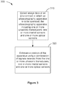
- Figure 3 illustrates an example of a method for estimating a position of an ultrasonography apparatus.
- the ultrasonography apparatus may include one or more ultrasonic transducers, one or more inertial sensors, one or more optical sensors and a processor communicatively coupled with the one or more ultrasonic transducers, the one or more inertial sensors and the one or more optical sensors.
- method 300 includes a block 310 for collecting, with the optical sensor and/or the ultrasonic transducer, image data of an environment in which the ultrasonic imaging probe is to be operated.
- the method proceeds, at block 320, with estimating, using the processor, a position of the apparatus using a combination of signals received from the one or more of the ultrasonic transducers, the one or more inertial sensors and the one or more optical sensors.
- the processor may use outputs from the optical sensor and/or the ultrasonic transducer to correct for accumulated drift errors of the inertial sensor.
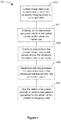
- Figure 4 illustrates an example of a method for calibrating an inertial sensor of a hand-held ultrasonic imaging probe and, according to an implementation.
- the imaging probe may include an ultrasonic transducer, an inertial sensor and a processor communicatively coupled with the ultrasonic transducer the inertial sensor and the optical sensor.
- method 400 includes a block 410 for collecting, with one or both of the optical sensor and the ultrasonic transducer, image data of an environment in which the ultrasonic imaging probe is to be operated.
- the method proceeds, at block 420, with calibrating, using the processor, the inertial sensor, using outputs from the optical sensor and/or ultrasonic transducer.
- the processor may use the outputs to correct for accumulated drift errors of the inertial sensor.
- the method 400 may proceed at block 430 with combining, with the processor, outputs from the inertial sensor and from one or both of the optical sensor and the ultrasonic transducer.
- the method 400 may proceed at block 440 with determining with the processor the spatial position of the ultrasound transducer with the combined outputs obtained at block 430.
- the method 400 may proceed at block 450 with using the spatial position, determined at block 440, to provide navigational guidance for movement of the ultrasonic imaging probe. Navigational guidance may be provided to an operator using the ultrasonic imaging probe to perform noninvasive medical ultrasonography.
- the processor may be configured to process ultrasound image data from the ultrasonic transducer and calibrate the estimated 6-DoF spatial position of the apparatus 100 using the processed ultrasound image data optical sensor image data.
- Figure 5 illustrates an example of a data flow diagram according to an implementation.
- the processor 140 processes ultrasound image data 515, inertial sensor data 525, and optical sensor image data 535.
- outputs from each of the ultrasonic transducer 110, the inertial sensor 120, and the optical sensor 130 may be fused so as to obtain a more accurately calibrated estimation of the spatial position of the apparatus 100.
- the processor may be configured to adjust one or more of the 2-D image frames in view of the estimated 6-DoF spatial position at the time of obtaining each respective 2-D image. For example where the estimated 6-DoF spatial position at a time corresponding to a 2-D image frame (i) is different from the estimated 6-DoF spatial position at a time corresponding to a 2-D image frame (i+1), one or both of the respective 2-D image frames may be adjusted to compensate for the difference. As a result, temporal series of 2-D images may be more accurately combined to compute 3-D image data 560.
- the processor may be configured to make a determination whether or not an obtained 2-D image frame relates to a first volume under examination or a different volume. For example, where an operator interrupts and then resumes use of the apparatus (e.g., by lifting if up from a first location and then setting it down at a second location), the operator may or may not intend that the first location and the second location be substantially identical.
- the processor may be configured to determine, with regard to a newly received 2-D image frame, whether data from the 2-D image frame should be merged with previously received image frame data (because the first location and the second location are substantially identical) or not merged (because the first location and the second location are not substantially identical).
- the processor may be configured to determine a difference between two or more 2-D image frames and compare the difference to a threshold to determine if the images relate to approximately the same location.
- the processor may be configured to compare the 6-DoF spatial position, as well as operator settings of the ultrasound probe (e.g., frequency and gain, image depth and signal processing filter parameters) associated with the two or more 2-D image frames to determine if they should be associated with the same volume.
- Figure 6 illustrates an example of an environment in which the hand-held ultrasonic imaging probe may be operated according to another implementation.
- the apparatus 100 includes the processor 140 communicatively coupled with one or more optical sensors 130
- the processor 140 may be configured to collect image data of an environment (for example, an examining room) in which a subject is to be examined using the apparatus.
- the examining room includes a plurality of optical emitters 501 configured for optical wireless communication (OWC).
- OWC optical wireless communication
- the optical sensors 130 may be optically coupled so as to receive signals from the emitters 601, which may be configured as part of an indoor positioning system (IPS).
- the optical emitters are configured for visible light communication (VLC).
- the optical emitters may be configured for communication in the infrared and/or ultraviolet light wavelengths.
- the IPS may enable the processor to calculate, in real time, the probe's X, Y and Z location as well as the probe's pitch, yaw, and roll orientation with respect to the optical emitters 601.
- the processor may be configured to calculate, in real time, location of the subject or an anatomical feature of the subject, with or without use of an inertial sensor.
- the processor 140 may also be communicatively coupled with at least one inertial sensor 120.
- the inertial sensor 120 may be configured to measure translational and rotational motion of the apparatus 100.
- the processor may be configured to estimate, in real-time, the probe's spatial position notwithstanding that some or all of the optical emitters 601 may be obscured from view of the optical sensors, and notwithstanding normal inertial sensor drift error accumulation.
- a smart device for ultrasound imaging is configured as an ultrasonic imaging probe that includes an inertial sensor and an optical sensor where the processor is configured to calibrate the inertial sensor using outputs from the optical sensor. It will be appreciated that a number of alternative configurations and fabrication techniques may be contemplated.
- a phrase referring to "at least one of' a list of items refers to any combination of those items, including single members.
- "at least one of: a, b, or c” is intended to cover: a, b, c, a-b, a-c, b-c, and a-b-c.
- the hardware and data processing apparatus used to implement the various illustrative logics, logical blocks, modules and circuits described in connection with the aspects disclosed herein may be implemented or performed with a general purpose single- or multi-chip processor, a digital signal processor (DSP), an application specific integrated circuit (ASIC), a field programmable gate array (FPGA) or other programmable logic device, discrete gate or transistor logic, discrete hardware components, or any combination thereof designed to perform the functions described herein.
- a general purpose processor may be a microprocessor or any conventional processor, controller, microcontroller, or state machine.
- a processor also may be implemented as a combination of computing devices, e.g., a combination of a DSP and a microprocessor, a plurality of microprocessors, one or more microprocessors in conjunction with a DSP core, or any other such configuration.
- particular processes and methods may be performed by circuitry that is specific to a given function.
- the functions described may be implemented in hardware, digital electronic circuitry, computer software, firmware, including the structures disclosed in this specification and their structural equivalents thereof, or in any combination thereof. Implementations of the subject matter described in this specification also can be implemented as one or more computer programs, i.e., one or more modules of computer program instructions, encoded on a computer storage media for execution by or to control the operation of data processing apparatus.
- the functions may be stored on or transmitted over as one or more instructions or code on a computer-readable medium, such as a non-transitory medium.
- a computer-readable medium such as a non-transitory medium.
- the processes of a method or algorithm disclosed herein may be implemented in a processor-executable software module which may reside on a computer-readable medium.
- Computer-readable media include both computer storage media and communication media including any medium that can be enabled to transfer a computer program from one place to another. Storage media may be any available media that may be accessed by a computer.
- non-transitory media may include RAM, ROM, EEPROM, CD-ROM or other optical disk storage, magnetic disk storage or other magnetic storage devices, or any other medium that may be used to store desired program code in the form of instructions or data structures and that may be accessed by a computer.
- any connection can be properly termed a computer-readable medium.
- Disk and disc includes compact disc (CD), laser disc, optical disc, digital versatile disc (DVD), floppy disk, and blu-ray disc where disks usually reproduce data magnetically, while discs reproduce data optically with lasers. Combinations of the above should also be included within the scope of computer-readable media.
- the operations of a method or algorithm may reside as one or any combination or set of codes and instructions on a machine readable medium and computer-readable medium, which may be incorporated into a computer program product.
Landscapes
- Health & Medical Sciences (AREA)
- Life Sciences & Earth Sciences (AREA)
- Engineering & Computer Science (AREA)
- Physics & Mathematics (AREA)
- Radar, Positioning & Navigation (AREA)
- Remote Sensing (AREA)
- Animal Behavior & Ethology (AREA)
- Medical Informatics (AREA)
- Veterinary Medicine (AREA)
- Biophysics (AREA)
- Nuclear Medicine, Radiotherapy & Molecular Imaging (AREA)
- Pathology (AREA)
- Radiology & Medical Imaging (AREA)
- Biomedical Technology (AREA)
- Heart & Thoracic Surgery (AREA)
- Public Health (AREA)
- Molecular Biology (AREA)
- Surgery (AREA)
- General Health & Medical Sciences (AREA)
- Computer Vision & Pattern Recognition (AREA)
- Automation & Control Theory (AREA)
- General Physics & Mathematics (AREA)
- Gynecology & Obstetrics (AREA)
- Ultra Sonic Daignosis Equipment (AREA)
- Physiology (AREA)
- Computer Networks & Wireless Communication (AREA)
Claims (15)
- Vorrichtung für Ultraschalluntersuchungen, wobei die Vorrichtung umfasst:eine Bilderfassungssonde mit einem oder mehreren Ultraschallwandlern (110);einen oder mehrere Trägheitssensoren (120) und einen oder mehrere optische Sensoren (130); undeinen Prozessor (140), der kommunikativ mit dem einen oder den mehreren Ultraschallwandlern, mit dem einen oder den mehreren Trägheitssensoren und mit dem einen oder den mehreren optischen Sensoren gekoppelt ist;dadurch gekennzeichnet, dassder Prozessor in der Lage ist zum:Kalibrieren von Ausgaben des einen oder der mehreren Trägheitssensoren mittels Korrigieren von Driftfehler-Akkumulation des einen oder der mehreren Trägheitssensoren unter Verwendung einer Kombination von Signalen, die von dem einen oder den mehreren Ultraschallwandlern und von dem einen oder den mehreren optischen Sensoren empfangen wurden; undSchätzen einer Position der Bilderfassungssonde basierend auf den kalibrierten Ausgaben des einen oder der mehreren Trägheitssensoren.
- Die Vorrichtung nach Anspruch 1, wobei das Schätzen der Position der Bilderfassungssonde Folgendes umfasst:Verarbeiten von Ultraschallbilddaten von dem einen oder den mehreren Ultraschallwandlern; undBestimmen der Position basierend auf den verarbeiteten Ultraschallbilddaten.
- Die Vorrichtung nach Anspruch 2, wobei die Ultraschallbilddaten eine Reihe von 2-D-Bildframes umfassen und wobei die verarbeiteten Ultraschallbilddaten ein 3-D-Bild umfassen; und
wobei der Prozessor eingerichtet ist, mindestens einen der 2-D-Bildframes in Anbetracht der ermittelten Position zu einem Zeitpunkt des Erfassens des mindestens einen der 2-D-Bilder anzupassen. - Die Vorrichtung nach Anspruch 2, wobei die Ultraschallbilddaten eine Reihe von 2-D-Bildframes umfassen und wobei die verarbeiteten Ultraschallbilddaten ein 3-D-Bild eines ersten Volumens umfassen; und
wobei der Prozessor eingerichtet ist, bezüglich mindestens eines der 2-D-Bildframes zu bestimmen, ob sich der mindestens eine der 2-D-Bildframes auf das erste Volumen oder auf ein anderes Volumen bezieht. - Die Vorrichtung nach Anspruch 1, wobei der optische Sensor optisch mit einem oder mehreren optischen, drahtlosen Kommunikationsemittern eines Indoor-Positionierungssystems gekoppelt ist.
- Die Vorrichtung nach Anspruch 1, wobei der Prozessor eingerichtet ist, Bilddaten zu verarbeiten, die von dem einen oder von den beiden optischen Sensoren und von den Ultraschallwandlern erfasst wurden, um eine Vielzahl von Orientierungspunkten auszuwählen.
- Die Vorrichtung nach Anspruch 6, wobei die Orientierungspunkte mindestens einen der beiden folgenden Aspekte umfassen:einen oder mehrere Punkte, Kanten oder Ecken von gewöhnlichen Oberflächen, Einbauten oder Objekten eines Raumes, in dem die Vorrichtung verwendet werden soll, um einen Gegenstand zu untersuchen; undein oder mehrere anatomische Merkmale des Gegenstandes, wobei die anatomischen Merkmale aus der Gruppe bestehend aus Gewebeoberflächen, Gewebegrenzen und Bildtextur von gewöhnlichen anatomischen oder pathologischen Strukturen des Gegenstandes ausgewählt werden.
- Die Vorrichtung nach Anspruch 7, wobei der Prozessor eingerichtet ist zum Berechnen der Position der Bilderfassungssonde in Bezug auf die Orientierungspunkte, auf eine Position des Gegenstandes oder auf ein anatomisches Merkmal des Gegenstandes.
- Die Vorrichtung nach Anspruch 1, wobei der Prozessor eingerichtet ist, die Kombination von Signalen zu koppeln, und zwar unter Verwendung einer oder mehrerer visueller Trägheits-Odometrietechniken, gleichzeitiger Lokalisierungs- und Abbildungstechniken, Bildregistrierungstechniken oder jedweder Kombination hieraus.
- Die Vorrichtung nach Anspruch 9, wobei der Prozessor eingerichtet ist zum: Verarbeiten von Ultraschallbilddaten von dem Ultraschallwandler; und
Bestimmen der Position der Bilderfassungssonde aus den bearbeiteten Ultraschallbilddaten. - Verfahren für Ultraschalluntersuchungen, wobei das Verfahren Folgendes aufweist:
Sammeln (310, 410) von Bilddaten einer Umgebung, in der eine Vorrichtung für Ultraschalluntersuchungen verwendet werden soll, wobei die Ultraschallvorrichtung Folgendes aufweist:einen Prozessor und eine Bilderfassungssonde mit einem oder mehreren Ultraschallwandlern, einen oder mehrere Trägheitssensoren und einen oder mehrere optische Sensoren,wobei der Prozessor kommunikativ mit dem einen oder den mehreren Ultraschallwandlern, mit dem einen oder den mehreren Trägheitssensoren und mit dem einen oder den mehreren optischen Sensoren gekoppelt ist, wobei die Ultraschallvorrichtung eingerichtet ist, nicht-invasive, medizinische Ultraschalluntersuchungen durchzuführen;dadurch gekennzeichnet, dass das Verfahren weiterhin aufweist:Kalibrieren (420) von Ausgaben des einen oder der mehreren Trägheitssensoren mittels Korrigieren von Driftfehler-Akkumulation des einen oder der mehreren Trägheitssensoren unter Verwendung einer Kombination von Signalen, die von dem einen oder den mehreren Ultraschallwandlern und von dem einen oder den mehreren optischen Sensoren empfangen wurden; undSchätzen, mit dem Prozessor, einer Position der Bilderfassungssonde basierend auf den kalibrierten Ausgaben des einen oder der mehreren Trägheitssensoren. - Das Verfahren nach Anspruch 11, welches weiterhin aufweist:
Koppeln, mit dem Prozessor, der Kombination von Signalen unter Verwendung eines oder mehrerer visueller Trägheits-Odometrietechniken, simultaner Lokalisierungs- und Abbildungstechniken, Bildregistrierungstechniken oder jedweder Kombination hieraus. - Das Verfahren nach Anspruch 11, wobei die Bilddaten Ausgaben von dem einem oder von den beiden der optischen Sensoren und von den Ultraschallwandlern umfassen;
wobei der Prozessor eingerichtet ist, die Bilddaten zu verarbeiten, so dass eine Vielzahl von Orientierungspunkten ausgewählt wird, wobei die Orientierungspunkte mindestens einen der beiden folgenden Aspekte umfassen:einen oder mehrere Punkte, Kanten oder Ecken von gewöhnlichen Oberflächen, Einbauten oder Objekten eines Raumes, in dem die Vorrichtung verwendet werden soll, um einen Gegenstand zu untersuchen; undein oder mehrere anatomische Merkmale des Gegenstandes, wobei die anatomischen Merkmale aus der Gruppe bestehend aus Gewebeoberflächen, Gewebegrenzen und Bildtextur von gewöhnlichen anatomischen oder pathologischen Strukturen des Gegenstandes ausgewählt werden; undwobei der Prozessor eingerichtet ist, die Position der Bilderfassungssonde bezüglich der Orientierungspunkte zu bestimmen. - Das Verfahren nach Anspruch 11, das ferner das Verwenden (450) der bestimmten Position aufweist, um einem Benutzer der Vorrichtung Navigationshilfen für eine Bewegung der Bilderfassungssonde bereitzustellen.
- Nichtflüchtiges, computerlesbares Medium, auf dem Software gespeichert ist, wobei die Software Anweisungen für Ultraschalluntersuchungen umfasst, wobei die Anweisungen die Vorrichtung zur Durchführung eines Verfahrens nach einem der Ansprüche 11 bis 14 veranlassen.
Applications Claiming Priority (6)
| Application Number | Priority Date | Filing Date | Title |
|---|---|---|---|
| US201562153978P | 2015-04-28 | 2015-04-28 | |
| US201562153970P | 2015-04-28 | 2015-04-28 | |
| US201562153974P | 2015-04-28 | 2015-04-28 | |
| US15/140,006 US20160317127A1 (en) | 2015-04-28 | 2016-04-27 | Smart device for ultrasound imaging |
| US15/140,001 US20160317122A1 (en) | 2015-04-28 | 2016-04-27 | In-device fusion of optical and inertial positional tracking of ultrasound probes |
| PCT/US2016/029784 WO2016176452A1 (en) | 2015-04-28 | 2016-04-28 | In-device fusion of optical and inertial positional tracking of ultrasound probes |
Publications (2)
| Publication Number | Publication Date |
|---|---|
| EP3288465A1 EP3288465A1 (de) | 2018-03-07 |
| EP3288465B1 true EP3288465B1 (de) | 2019-02-20 |
Family
ID=57203893
Family Applications (1)
| Application Number | Title | Priority Date | Filing Date |
|---|---|---|---|
| EP16720692.9A Not-in-force EP3288465B1 (de) | 2015-04-28 | 2016-04-28 | Vorrichtungsinterne fusion von optischer und inerter positionsverfolgung von ultraschallsonden |
Country Status (3)
| Country | Link |
|---|---|
| US (2) | US20160317127A1 (de) |
| EP (1) | EP3288465B1 (de) |
| CN (1) | CN108601578B (de) |
Cited By (1)
| Publication number | Priority date | Publication date | Assignee | Title |
|---|---|---|---|---|
| US12189106B2 (en) | 2021-04-19 | 2025-01-07 | Carl Zeiss Meditec Ag | Microinstrument system and method for recording an image by fibre-optic scanning, and computer-implemented method for generating an image |
Families Citing this family (30)
| Publication number | Priority date | Publication date | Assignee | Title |
|---|---|---|---|---|
| US10925579B2 (en) | 2014-11-05 | 2021-02-23 | Otsuka Medical Devices Co., Ltd. | Systems and methods for real-time tracking of a target tissue using imaging before and during therapy delivery |
| US10360718B2 (en) * | 2015-08-14 | 2019-07-23 | Samsung Electronics Co., Ltd. | Method and apparatus for constructing three dimensional model of object |
| US20180129900A1 (en) * | 2016-11-04 | 2018-05-10 | Siemens Healthcare Gmbh | Anonymous and Secure Classification Using a Deep Learning Network |
| US10127659B2 (en) * | 2016-11-23 | 2018-11-13 | General Electric Company | Deep learning medical systems and methods for image acquisition |
| US11832969B2 (en) * | 2016-12-22 | 2023-12-05 | The Johns Hopkins University | Machine learning approach to beamforming |
| WO2018130370A1 (en) * | 2017-01-11 | 2018-07-19 | Contextvision Ab | Methods and systems for automatic control of subjective image quality in imaging of objects |
| US20200158517A1 (en) | 2017-01-19 | 2020-05-21 | Mindmaze Holding Sa | System, methods, device and apparatuses for preforming simultaneous localization and mapping |
| JP2020516370A (ja) * | 2017-04-17 | 2020-06-11 | アヴェント インコーポレイテッド | ディープラーニングネットワークを用いて解剖学的対象物を分析するための関節運動式アーム |
| US11276163B2 (en) | 2017-05-02 | 2022-03-15 | Alvitae LLC | System and method for facilitating autonomous control of an imaging system |
| WO2019025332A1 (en) | 2017-07-31 | 2019-02-07 | Koninklijke Philips N.V. | SYSTEM AND METHOD FOR DETECTING MISUSE OF A MEDICAL IMAGING SYSTEM |
| US11948345B2 (en) * | 2018-04-09 | 2024-04-02 | Koninklijke Philips N.V. | Ultrasound system with artificial neural network for retrieval of imaging parameter settings for recurring patient |
| US20190374165A1 (en) * | 2018-06-07 | 2019-12-12 | Canon Medical Systems Corporation | Image processing apparatus and method |
| WO2020020770A1 (en) * | 2018-07-26 | 2020-01-30 | Koninklijke Philips N.V. | Ultrasound system with automated dynamic setting of imaging parameters based on organ detection |
| US10482677B1 (en) * | 2018-11-20 | 2019-11-19 | Dell Products, L.P. | Distributed simultaneous localization and mapping (SLAM) in virtual, augmented, and mixed reality (xR) applications |
| US10936055B2 (en) * | 2019-01-24 | 2021-03-02 | Dell Products, L.P. | Encoding content for virtual, augmented, and mixed reality (xR) applications in connectivity-constrained environments |
| US10854012B1 (en) * | 2019-05-29 | 2020-12-01 | Dell Products, L.P. | Concealing loss of distributed simultaneous localization and mapping (SLAM) data in edge cloud architectures |
| US12014823B2 (en) | 2019-08-30 | 2024-06-18 | GE Precision Healthcare LLC | Methods and systems for computer-aided diagnosis with deep learning models |
| US11182969B2 (en) * | 2019-10-29 | 2021-11-23 | Embraer S.A. | Spatial localization using augmented reality |
| EP4072426B1 (de) * | 2019-12-13 | 2025-04-16 | Smith&Nephew, Inc. | Extraktion und darstellung anatomischer merkmale unter verwendung von erweiterter realität |
| CN111062906B (zh) * | 2019-12-25 | 2023-06-30 | 浙江杜比医疗科技有限公司 | 散射光学成像乳房图像融合方法及其系统 |
| CN113155116B (zh) * | 2020-01-22 | 2025-10-31 | 无锡祥生医疗科技股份有限公司 | 超声扫查导航方法、装置及存储介质 |
| US11202103B1 (en) * | 2020-07-15 | 2021-12-14 | Netflix, Inc. | Techniques for limiting the influence of image enhancement operations on perceptual video quality estimations |
| US11113894B1 (en) * | 2020-09-11 | 2021-09-07 | Microsoft Technology Licensing, Llc | Systems and methods for GPS-based and sensor-based relocalization |
| EP4000531A1 (de) * | 2020-11-11 | 2022-05-25 | Koninklijke Philips N.V. | Verfahren und systeme zur verfolgung einer bewegung einer sonde in einem ultraschallsystem |
| CN114601493A (zh) * | 2020-12-09 | 2022-06-10 | 财团法人工业技术研究院 | 超声波扫描操作引导系统与超声波扫描操作引导方法 |
| EP4063892B1 (de) * | 2021-03-23 | 2025-08-27 | Nokia Technologies Oy | Entfernungsmessung ohne sichtlinie |
| CN113288209B (zh) * | 2021-06-04 | 2025-07-01 | 深圳开立生物医疗科技股份有限公司 | 一种超声成像设备、超声探头的位置信息获取方法及介质 |
| US12446854B2 (en) * | 2021-08-03 | 2025-10-21 | Fujifilm Sonosite, Inc. | Ultrasound probe guidance |
| CN114886459A (zh) * | 2021-08-27 | 2022-08-12 | 中山大学孙逸仙纪念医院 | 采集超声操作手法数据的系统、方法、装置、设备及介质 |
| WO2023129685A1 (en) * | 2021-12-29 | 2023-07-06 | Exo Imaging, Inc. | Low-cost, high-performance ultrasound imaging probe |
Family Cites Families (15)
| Publication number | Priority date | Publication date | Assignee | Title |
|---|---|---|---|---|
| WO2005065407A2 (en) * | 2003-12-30 | 2005-07-21 | Liposonix, Inc. | Position tracking device |
| DE112005000738T5 (de) * | 2004-03-29 | 2007-04-26 | Evolution Robotics, Inc., Pasadena | Verfahren und Vorrichtung zur Positionsbestimmung unter Verwendung von reflektierten Lichtquellen |
| US8348846B2 (en) * | 2008-09-30 | 2013-01-08 | Mediri Gmbh | 3D motion detection and correction by object tracking in ultrasound images |
| CN102365653B (zh) * | 2009-03-27 | 2015-02-25 | 皇家飞利浦电子股份有限公司 | 对医学成像的改进 |
| CA2767509C (en) * | 2009-07-09 | 2015-04-21 | Ohio University | Carbon fiber composite discharge electrode |
| US8900146B2 (en) * | 2009-07-27 | 2014-12-02 | The Hong Kong Polytechnic University | Three-dimensional (3D) ultrasound imaging system for assessing scoliosis |
| US20110306025A1 (en) * | 2010-05-13 | 2011-12-15 | Higher Education | Ultrasound Training and Testing System with Multi-Modality Transducer Tracking |
| EP2680778B1 (de) * | 2011-03-03 | 2019-07-31 | Koninklijke Philips N.V. | System und verfahren zur automatisierten initialisierung und registrierung eines navigationssystems |
| US20120277588A1 (en) * | 2011-04-26 | 2012-11-01 | General Electric Company | Systems and methods for fusing sensor and image data for three-dimensional volume reconstruction |
| WO2013005123A1 (en) * | 2011-07-01 | 2013-01-10 | Koninklijke Philips Electronics N.V. | Object-pose-based initialization of an ultrasound beamformer |
| WO2013040693A1 (en) * | 2011-09-23 | 2013-03-28 | Hamid Reza Tizhoosh | Computer system and method for atlas-based consensual and consistent contouring of medical images |
| US20130225999A1 (en) * | 2012-02-29 | 2013-08-29 | Toshiba Medical Systems Corporation | Gesture commands user interface for ultrasound imaging systems |
| CA3228582A1 (en) * | 2012-03-07 | 2013-09-12 | Ziteo, Inc. | Methods and systems for tracking and guiding sensors and instruments |
| US9504445B2 (en) * | 2013-02-28 | 2016-11-29 | General Electric Company | Ultrasound imaging system and method for drift compensation |
| US10835210B2 (en) * | 2015-03-30 | 2020-11-17 | Siemens Medical Solutions Usa, Inc. | Three-dimensional volume of interest in ultrasound imaging |
-
2016
- 2016-04-27 US US15/140,006 patent/US20160317127A1/en not_active Abandoned
- 2016-04-27 US US15/140,001 patent/US20160317122A1/en not_active Abandoned
- 2016-04-28 EP EP16720692.9A patent/EP3288465B1/de not_active Not-in-force
- 2016-04-28 CN CN201680024340.5A patent/CN108601578B/zh not_active Expired - Fee Related
Non-Patent Citations (1)
| Title |
|---|
| None * |
Cited By (1)
| Publication number | Priority date | Publication date | Assignee | Title |
|---|---|---|---|---|
| US12189106B2 (en) | 2021-04-19 | 2025-01-07 | Carl Zeiss Meditec Ag | Microinstrument system and method for recording an image by fibre-optic scanning, and computer-implemented method for generating an image |
Also Published As
| Publication number | Publication date |
|---|---|
| US20160317127A1 (en) | 2016-11-03 |
| EP3288465A1 (de) | 2018-03-07 |
| CN108601578B (zh) | 2021-04-09 |
| US20160317122A1 (en) | 2016-11-03 |
| CN108601578A (zh) | 2018-09-28 |
Similar Documents
| Publication | Publication Date | Title |
|---|---|---|
| EP3288465B1 (de) | Vorrichtungsinterne fusion von optischer und inerter positionsverfolgung von ultraschallsonden | |
| Suligoj et al. | RobUSt–an autonomous robotic ultrasound system for medical imaging | |
| US9504445B2 (en) | Ultrasound imaging system and method for drift compensation | |
| AU2021265595B2 (en) | A system and a method for allowing a non-skilled user to acquire ultrasound images of internal organs of a human body | |
| EP2185077B1 (de) | Diagnostisches ultraschall-bildgebungssystem und kontrollverfahren dafür | |
| WO2016176452A1 (en) | In-device fusion of optical and inertial positional tracking of ultrasound probes | |
| JP2008275340A (ja) | 情報処理装置、情報処理方法 | |
| WO2015187866A1 (en) | In-time registration of temporally separated image acquisition | |
| KR20140148247A (ko) | 모바일 x 선 장치의 x 선 튜브와 디텍터를 정렬하기 위한 정보 제공 방법 및 정보 제공 장치, 및 무선 디텍터 | |
| US20170270678A1 (en) | Device and method for image registration, and non-transitory recording medium | |
| US20180221093A1 (en) | Systems and methods for soft tissue navigation | |
| US20210068781A1 (en) | Ultrasonic imaging system | |
| JP2014212904A (ja) | 医用投影システム | |
| Sun et al. | Computer-guided ultrasound probe realignment by optical tracking | |
| CN121941454A (zh) | 盲扫协议中超声探头引导的超声成像 | |
| Zhetpissov et al. | A-SEE2. 0: Active-Sensing End-Effector for Robotic Ultrasound Systems with Dense Contact Surface Perception Enabled Probe Orientation Adjustment | |
| WO2024158804A1 (en) | Devices and methods for freehand multimodality imaging | |
| EP4305586A1 (de) | Systeme und verfahren zur verbesserung von 3d-bildern und navigation durch integration von patientenbewegungsdaten | |
| Claasen | Smart motion sensor for navigated prosthetic surgery |
Legal Events
| Date | Code | Title | Description |
|---|---|---|---|
| STAA | Information on the status of an ep patent application or granted ep patent |
Free format text: STATUS: THE INTERNATIONAL PUBLICATION HAS BEEN MADE |
|
| PUAI | Public reference made under article 153(3) epc to a published international application that has entered the european phase |
Free format text: ORIGINAL CODE: 0009012 |
|
| STAA | Information on the status of an ep patent application or granted ep patent |
Free format text: STATUS: REQUEST FOR EXAMINATION WAS MADE |
|
| 17P | Request for examination filed |
Effective date: 20170920 |
|
| AK | Designated contracting states |
Kind code of ref document: A1 Designated state(s): AL AT BE BG CH CY CZ DE DK EE ES FI FR GB GR HR HU IE IS IT LI LT LU LV MC MK MT NL NO PL PT RO RS SE SI SK SM TR |
|
| AX | Request for extension of the european patent |
Extension state: BA ME |
|
| DAV | Request for validation of the european patent (deleted) | ||
| DAX | Request for extension of the european patent (deleted) | ||
| GRAP | Despatch of communication of intention to grant a patent |
Free format text: ORIGINAL CODE: EPIDOSNIGR1 |
|
| STAA | Information on the status of an ep patent application or granted ep patent |
Free format text: STATUS: GRANT OF PATENT IS INTENDED |
|
| INTG | Intention to grant announced |
Effective date: 20180830 |
|
| RIN1 | Information on inventor provided before grant (corrected) |
Inventor name: DOS SANTOS MENDONCA, RICARDO PAULO Inventor name: LUNDQVIST, PATRIK NILS Inventor name: JAIN, RAJEEV Inventor name: JAGANNATHAN, PADMAPRIYA Inventor name: ATTAR, RASHID AHMED AKBAR |
|
| GRAS | Grant fee paid |
Free format text: ORIGINAL CODE: EPIDOSNIGR3 |
|
| GRAA | (expected) grant |
Free format text: ORIGINAL CODE: 0009210 |
|
| STAA | Information on the status of an ep patent application or granted ep patent |
Free format text: STATUS: THE PATENT HAS BEEN GRANTED |
|
| AK | Designated contracting states |
Kind code of ref document: B1 Designated state(s): AL AT BE BG CH CY CZ DE DK EE ES FI FR GB GR HR HU IE IS IT LI LT LU LV MC MK MT NL NO PL PT RO RS SE SI SK SM TR |
|
| REG | Reference to a national code |
Ref country code: GB Ref legal event code: FG4D |
|
| REG | Reference to a national code |
Ref country code: CH Ref legal event code: EP |
|
| REG | Reference to a national code |
Ref country code: AT Ref legal event code: REF Ref document number: 1097131 Country of ref document: AT Kind code of ref document: T Effective date: 20190315 |
|
| REG | Reference to a national code |
Ref country code: IE Ref legal event code: FG4D |
|
| REG | Reference to a national code |
Ref country code: DE Ref legal event code: R096 Ref document number: 602016010152 Country of ref document: DE |
|
| REG | Reference to a national code |
Ref country code: LT Ref legal event code: MG4D |
|
| REG | Reference to a national code |
Ref country code: NL Ref legal event code: MP Effective date: 20190220 |
|
| PG25 | Lapsed in a contracting state [announced via postgrant information from national office to epo] |
Ref country code: SE Free format text: LAPSE BECAUSE OF FAILURE TO SUBMIT A TRANSLATION OF THE DESCRIPTION OR TO PAY THE FEE WITHIN THE PRESCRIBED TIME-LIMIT Effective date: 20190220 Ref country code: NO Free format text: LAPSE BECAUSE OF FAILURE TO SUBMIT A TRANSLATION OF THE DESCRIPTION OR TO PAY THE FEE WITHIN THE PRESCRIBED TIME-LIMIT Effective date: 20190520 Ref country code: PT Free format text: LAPSE BECAUSE OF FAILURE TO SUBMIT A TRANSLATION OF THE DESCRIPTION OR TO PAY THE FEE WITHIN THE PRESCRIBED TIME-LIMIT Effective date: 20190620 Ref country code: LT Free format text: LAPSE BECAUSE OF FAILURE TO SUBMIT A TRANSLATION OF THE DESCRIPTION OR TO PAY THE FEE WITHIN THE PRESCRIBED TIME-LIMIT Effective date: 20190220 Ref country code: FI Free format text: LAPSE BECAUSE OF FAILURE TO SUBMIT A TRANSLATION OF THE DESCRIPTION OR TO PAY THE FEE WITHIN THE PRESCRIBED TIME-LIMIT Effective date: 20190220 |
|
| PG25 | Lapsed in a contracting state [announced via postgrant information from national office to epo] |
Ref country code: BG Free format text: LAPSE BECAUSE OF FAILURE TO SUBMIT A TRANSLATION OF THE DESCRIPTION OR TO PAY THE FEE WITHIN THE PRESCRIBED TIME-LIMIT Effective date: 20190520 Ref country code: RS Free format text: LAPSE BECAUSE OF FAILURE TO SUBMIT A TRANSLATION OF THE DESCRIPTION OR TO PAY THE FEE WITHIN THE PRESCRIBED TIME-LIMIT Effective date: 20190220 Ref country code: NL Free format text: LAPSE BECAUSE OF FAILURE TO SUBMIT A TRANSLATION OF THE DESCRIPTION OR TO PAY THE FEE WITHIN THE PRESCRIBED TIME-LIMIT Effective date: 20190220 Ref country code: IS Free format text: LAPSE BECAUSE OF FAILURE TO SUBMIT A TRANSLATION OF THE DESCRIPTION OR TO PAY THE FEE WITHIN THE PRESCRIBED TIME-LIMIT Effective date: 20190620 Ref country code: LV Free format text: LAPSE BECAUSE OF FAILURE TO SUBMIT A TRANSLATION OF THE DESCRIPTION OR TO PAY THE FEE WITHIN THE PRESCRIBED TIME-LIMIT Effective date: 20190220 Ref country code: HR Free format text: LAPSE BECAUSE OF FAILURE TO SUBMIT A TRANSLATION OF THE DESCRIPTION OR TO PAY THE FEE WITHIN THE PRESCRIBED TIME-LIMIT Effective date: 20190220 Ref country code: GR Free format text: LAPSE BECAUSE OF FAILURE TO SUBMIT A TRANSLATION OF THE DESCRIPTION OR TO PAY THE FEE WITHIN THE PRESCRIBED TIME-LIMIT Effective date: 20190521 |
|
| REG | Reference to a national code |
Ref country code: AT Ref legal event code: MK05 Ref document number: 1097131 Country of ref document: AT Kind code of ref document: T Effective date: 20190220 |
|
| PG25 | Lapsed in a contracting state [announced via postgrant information from national office to epo] |
Ref country code: SK Free format text: LAPSE BECAUSE OF FAILURE TO SUBMIT A TRANSLATION OF THE DESCRIPTION OR TO PAY THE FEE WITHIN THE PRESCRIBED TIME-LIMIT Effective date: 20190220 Ref country code: RO Free format text: LAPSE BECAUSE OF FAILURE TO SUBMIT A TRANSLATION OF THE DESCRIPTION OR TO PAY THE FEE WITHIN THE PRESCRIBED TIME-LIMIT Effective date: 20190220 Ref country code: IT Free format text: LAPSE BECAUSE OF FAILURE TO SUBMIT A TRANSLATION OF THE DESCRIPTION OR TO PAY THE FEE WITHIN THE PRESCRIBED TIME-LIMIT Effective date: 20190220 Ref country code: EE Free format text: LAPSE BECAUSE OF FAILURE TO SUBMIT A TRANSLATION OF THE DESCRIPTION OR TO PAY THE FEE WITHIN THE PRESCRIBED TIME-LIMIT Effective date: 20190220 Ref country code: DK Free format text: LAPSE BECAUSE OF FAILURE TO SUBMIT A TRANSLATION OF THE DESCRIPTION OR TO PAY THE FEE WITHIN THE PRESCRIBED TIME-LIMIT Effective date: 20190220 Ref country code: AL Free format text: LAPSE BECAUSE OF FAILURE TO SUBMIT A TRANSLATION OF THE DESCRIPTION OR TO PAY THE FEE WITHIN THE PRESCRIBED TIME-LIMIT Effective date: 20190220 Ref country code: CZ Free format text: LAPSE BECAUSE OF FAILURE TO SUBMIT A TRANSLATION OF THE DESCRIPTION OR TO PAY THE FEE WITHIN THE PRESCRIBED TIME-LIMIT Effective date: 20190220 Ref country code: ES Free format text: LAPSE BECAUSE OF FAILURE TO SUBMIT A TRANSLATION OF THE DESCRIPTION OR TO PAY THE FEE WITHIN THE PRESCRIBED TIME-LIMIT Effective date: 20190220 |
|
| REG | Reference to a national code |
Ref country code: DE Ref legal event code: R097 Ref document number: 602016010152 Country of ref document: DE |
|
| PG25 | Lapsed in a contracting state [announced via postgrant information from national office to epo] |
Ref country code: SM Free format text: LAPSE BECAUSE OF FAILURE TO SUBMIT A TRANSLATION OF THE DESCRIPTION OR TO PAY THE FEE WITHIN THE PRESCRIBED TIME-LIMIT Effective date: 20190220 Ref country code: PL Free format text: LAPSE BECAUSE OF FAILURE TO SUBMIT A TRANSLATION OF THE DESCRIPTION OR TO PAY THE FEE WITHIN THE PRESCRIBED TIME-LIMIT Effective date: 20190220 |
|
| REG | Reference to a national code |
Ref country code: CH Ref legal event code: PL |
|
| REG | Reference to a national code |
Ref country code: BE Ref legal event code: MM Effective date: 20190430 |
|
| PLBE | No opposition filed within time limit |
Free format text: ORIGINAL CODE: 0009261 |
|
| STAA | Information on the status of an ep patent application or granted ep patent |
Free format text: STATUS: NO OPPOSITION FILED WITHIN TIME LIMIT |
|
| PG25 | Lapsed in a contracting state [announced via postgrant information from national office to epo] |
Ref country code: AT Free format text: LAPSE BECAUSE OF FAILURE TO SUBMIT A TRANSLATION OF THE DESCRIPTION OR TO PAY THE FEE WITHIN THE PRESCRIBED TIME-LIMIT Effective date: 20190220 Ref country code: LU Free format text: LAPSE BECAUSE OF NON-PAYMENT OF DUE FEES Effective date: 20190428 Ref country code: MC Free format text: LAPSE BECAUSE OF FAILURE TO SUBMIT A TRANSLATION OF THE DESCRIPTION OR TO PAY THE FEE WITHIN THE PRESCRIBED TIME-LIMIT Effective date: 20190220 |
|
| 26N | No opposition filed |
Effective date: 20191121 |
|
| PG25 | Lapsed in a contracting state [announced via postgrant information from national office to epo] |
Ref country code: LI Free format text: LAPSE BECAUSE OF NON-PAYMENT OF DUE FEES Effective date: 20190430 Ref country code: CH Free format text: LAPSE BECAUSE OF NON-PAYMENT OF DUE FEES Effective date: 20190430 |
|
| PG25 | Lapsed in a contracting state [announced via postgrant information from national office to epo] |
Ref country code: BE Free format text: LAPSE BECAUSE OF NON-PAYMENT OF DUE FEES Effective date: 20190430 Ref country code: SI Free format text: LAPSE BECAUSE OF FAILURE TO SUBMIT A TRANSLATION OF THE DESCRIPTION OR TO PAY THE FEE WITHIN THE PRESCRIBED TIME-LIMIT Effective date: 20190220 |
|
| PG25 | Lapsed in a contracting state [announced via postgrant information from national office to epo] |
Ref country code: TR Free format text: LAPSE BECAUSE OF FAILURE TO SUBMIT A TRANSLATION OF THE DESCRIPTION OR TO PAY THE FEE WITHIN THE PRESCRIBED TIME-LIMIT Effective date: 20190220 |
|
| PG25 | Lapsed in a contracting state [announced via postgrant information from national office to epo] |
Ref country code: IE Free format text: LAPSE BECAUSE OF NON-PAYMENT OF DUE FEES Effective date: 20190428 |
|
| PG25 | Lapsed in a contracting state [announced via postgrant information from national office to epo] |
Ref country code: CY Free format text: LAPSE BECAUSE OF FAILURE TO SUBMIT A TRANSLATION OF THE DESCRIPTION OR TO PAY THE FEE WITHIN THE PRESCRIBED TIME-LIMIT Effective date: 20190220 |
|
| PG25 | Lapsed in a contracting state [announced via postgrant information from national office to epo] |
Ref country code: MT Free format text: LAPSE BECAUSE OF FAILURE TO SUBMIT A TRANSLATION OF THE DESCRIPTION OR TO PAY THE FEE WITHIN THE PRESCRIBED TIME-LIMIT Effective date: 20190220 Ref country code: HU Free format text: LAPSE BECAUSE OF FAILURE TO SUBMIT A TRANSLATION OF THE DESCRIPTION OR TO PAY THE FEE WITHIN THE PRESCRIBED TIME-LIMIT; INVALID AB INITIO Effective date: 20160428 |
|
| PG25 | Lapsed in a contracting state [announced via postgrant information from national office to epo] |
Ref country code: MK Free format text: LAPSE BECAUSE OF FAILURE TO SUBMIT A TRANSLATION OF THE DESCRIPTION OR TO PAY THE FEE WITHIN THE PRESCRIBED TIME-LIMIT Effective date: 20190220 |
|
| PGFP | Annual fee paid to national office [announced via postgrant information from national office to epo] |
Ref country code: FR Payment date: 20230320 Year of fee payment: 8 |
|
| PGFP | Annual fee paid to national office [announced via postgrant information from national office to epo] |
Ref country code: GB Payment date: 20230315 Year of fee payment: 8 |
|
| PGFP | Annual fee paid to national office [announced via postgrant information from national office to epo] |
Ref country code: DE Payment date: 20230320 Year of fee payment: 8 |
|
| REG | Reference to a national code |
Ref country code: DE Ref legal event code: R119 Ref document number: 602016010152 Country of ref document: DE |
|
| GBPC | Gb: european patent ceased through non-payment of renewal fee |
Effective date: 20240428 |
|
| PG25 | Lapsed in a contracting state [announced via postgrant information from national office to epo] |
Ref country code: DE Free format text: LAPSE BECAUSE OF NON-PAYMENT OF DUE FEES Effective date: 20241105 |
|
| PG25 | Lapsed in a contracting state [announced via postgrant information from national office to epo] |
Ref country code: GB Free format text: LAPSE BECAUSE OF NON-PAYMENT OF DUE FEES Effective date: 20240428 |
|
| PG25 | Lapsed in a contracting state [announced via postgrant information from national office to epo] |
Ref country code: FR Free format text: LAPSE BECAUSE OF NON-PAYMENT OF DUE FEES Effective date: 20240430 |
|
| PG25 | Lapsed in a contracting state [announced via postgrant information from national office to epo] |
Ref country code: GB Free format text: LAPSE BECAUSE OF NON-PAYMENT OF DUE FEES Effective date: 20240428 Ref country code: FR Free format text: LAPSE BECAUSE OF NON-PAYMENT OF DUE FEES Effective date: 20240430 Ref country code: DE Free format text: LAPSE BECAUSE OF NON-PAYMENT OF DUE FEES Effective date: 20241105 |