EP3288475B1 - Pedikelschraube mit knochengewinde von grossem durchmesser - Google Patents
Pedikelschraube mit knochengewinde von grossem durchmesser Download PDFInfo
- Publication number
- EP3288475B1 EP3288475B1 EP17722778.2A EP17722778A EP3288475B1 EP 3288475 B1 EP3288475 B1 EP 3288475B1 EP 17722778 A EP17722778 A EP 17722778A EP 3288475 B1 EP3288475 B1 EP 3288475B1
- Authority
- EP
- European Patent Office
- Prior art keywords
- thread
- proximal
- distal
- connection
- bone
- Prior art date
- Legal status (The legal status is an assumption and is not a legal conclusion. Google has not performed a legal analysis and makes no representation as to the accuracy of the status listed.)
- Active
Links
Images
Classifications
-
- A—HUMAN NECESSITIES
- A61—MEDICAL OR VETERINARY SCIENCE; HYGIENE
- A61B—DIAGNOSIS; SURGERY; IDENTIFICATION
- A61B17/00—Surgical instruments, devices or methods
- A61B17/56—Surgical instruments or methods for treatment of bones or joints; Devices specially adapted therefor
- A61B17/58—Surgical instruments or methods for treatment of bones or joints; Devices specially adapted therefor for osteosynthesis, e.g. bone plates, screws or setting implements
- A61B17/68—Internal fixation devices, including fasteners and spinal fixators, even if a part thereof projects from the skin
- A61B17/84—Fasteners therefor or fasteners being internal fixation devices
- A61B17/86—Pins or screws or threaded wires; nuts therefor
- A61B17/8685—Pins or screws or threaded wires; nuts therefor comprising multiple separate parts
-
- A—HUMAN NECESSITIES
- A61—MEDICAL OR VETERINARY SCIENCE; HYGIENE
- A61B—DIAGNOSIS; SURGERY; IDENTIFICATION
- A61B17/00—Surgical instruments, devices or methods
- A61B17/56—Surgical instruments or methods for treatment of bones or joints; Devices specially adapted therefor
- A61B17/58—Surgical instruments or methods for treatment of bones or joints; Devices specially adapted therefor for osteosynthesis, e.g. bone plates, screws or setting implements
- A61B17/68—Internal fixation devices, including fasteners and spinal fixators, even if a part thereof projects from the skin
- A61B17/70—Spinal positioners or stabilisers, e.g. stabilisers comprising fluid filler in an implant
- A61B17/7001—Screws or hooks combined with longitudinal elements which do not contact vertebrae
- A61B17/7032—Screws or hooks with U-shaped head or back through which longitudinal rods pass
-
- A—HUMAN NECESSITIES
- A61—MEDICAL OR VETERINARY SCIENCE; HYGIENE
- A61B—DIAGNOSIS; SURGERY; IDENTIFICATION
- A61B17/00—Surgical instruments, devices or methods
- A61B17/56—Surgical instruments or methods for treatment of bones or joints; Devices specially adapted therefor
- A61B17/58—Surgical instruments or methods for treatment of bones or joints; Devices specially adapted therefor for osteosynthesis, e.g. bone plates, screws or setting implements
- A61B17/68—Internal fixation devices, including fasteners and spinal fixators, even if a part thereof projects from the skin
- A61B17/70—Spinal positioners or stabilisers, e.g. stabilisers comprising fluid filler in an implant
- A61B17/7001—Screws or hooks combined with longitudinal elements which do not contact vertebrae
- A61B17/7035—Screws or hooks, wherein a rod-clamping part and a bone-anchoring part can pivot relative to each other
- A61B17/7037—Screws or hooks, wherein a rod-clamping part and a bone-anchoring part can pivot relative to each other wherein pivoting is blocked when the rod is clamped
-
- A—HUMAN NECESSITIES
- A61—MEDICAL OR VETERINARY SCIENCE; HYGIENE
- A61B—DIAGNOSIS; SURGERY; IDENTIFICATION
- A61B17/00—Surgical instruments, devices or methods
- A61B17/56—Surgical instruments or methods for treatment of bones or joints; Devices specially adapted therefor
- A61B17/58—Surgical instruments or methods for treatment of bones or joints; Devices specially adapted therefor for osteosynthesis, e.g. bone plates, screws or setting implements
- A61B17/68—Internal fixation devices, including fasteners and spinal fixators, even if a part thereof projects from the skin
- A61B17/84—Fasteners therefor or fasteners being internal fixation devices
- A61B17/86—Pins or screws or threaded wires; nuts therefor
- A61B17/8625—Shanks, i.e. parts contacting bone tissue
Definitions
- the present invention relates to a pedicle screw system comprising a receiving sleeve for a side member, a bone screw and a stem head element, wherein the bone screw has an externally threaded bone thread and an internally threaded connecting thread, wherein the stem element proximal (from the perspective of the surgeon) a head on the receiving sleeve is mounted, and distally (from the perspective of the surgeon) has an external thread formed as a connecting thread and is thus screwed into the connecting thread of the bone screw.
- Pedicle screws serve principally for the dorsal stabilization of the spine in the case of bruises, tumors, inflammations, deformities and degenerative instabilities by means of transpedicular screwing.
- pedicle screws are placed in the pedicles of each adjacent vertebra, whereupon an angularly stable connection between each axially superposed pedicle screws and an axially extending side member or web is created.
- the pedicle screws and side members thereby form a vortex stabilization system.
- a pedicle screw usually has an external thread extending in the axial direction as bone thread, to which a receiving sleeve (so-called tulip) adjoins the screw head side.
- tulip a receiving sleeve
- This forms a structurally U-shaped longitudinally slotted / tunneled receptacle with internal thread for receiving a longitudinal member, wherein the two radially opposite longitudinal slots each define a slot gap predetermined gap width.
- a locking element for example in the form of a grub screw, threaded nut or Setscrew, which is screwed into the internal thread, fixed.
- a mostly spherical or (semi-) spherical shaft head is surrounded by the receiving sleeve / tulip in a relatively pivotable manner and at the same time engages behind in the transition region between head and shaft.
- the receptacle sleeve / tulip can be pivoted and / or rotated relative to it, after the externally threaded shaft is buried in the pedicle channel of a vertebra, to obtain a desired position and orientation substantially independently of the alignment of the shaft.
- the undercut prevents that the receiving sleeve / tulip can be removed from the shaft head.
- pedicle screws with a large diameter bone thread are required.
- a polyaxial pedicle screw with large bone screw diameter may be problematic that the maximum possible bone screw diameter is determined and limited by the geometry and dimensions of the receiving sleeve. Due to the design, however, the bone screw is to be guided from proximal to distal through the receiving sleeve, so that its shaft head comes to lie in the receiving sleeve when mounted. The reason for this is the requirement for the smallest possible head part or the smallest possible receiving sleeve and the resulting small inner diameter of the receiving sleeve.
- the applicant of this invention has already developed a multi-piece pedicle screw design having a bone screw and a stem head member.
- the bone screw has a bone thread designed as an external thread and a connecting thread formed as an internal thread.
- the shaft head element again has a head proximally for supporting the receiving sleeve and distally a connecting thread designed as an external thread.
- the shaft head element and the Bone screw are connected to each other via the connecting threads.
- the shaft head element can be designed to match the dimensions of the receiving sleeve, so that it can be passed through this from proximal to distal to the stop on the shaft head, while the bone screw from the distal direction, without to be guided through the receiving sleeve, can be screwed onto the pre-assembled in the receiving sleeve shaft head element and is not limited in terms of its bone thread diameter.
- a possible problem with this multi-part pedicle screw may in certain cases be that the bone thread must be provided very shallow and conical in the region of the screw connection of the bone screw and the shaft head element, ie in the region of the connection screw connection, in order to ensure sufficient stability of the bone screw and the probability a fracture of the bone screw due to the thin wall between the bone thread and the connecting thread favored by their high notch effects to reduce or prevent.
- the bone screw has a cylindrical or approximately cylindrical threaded core instead of a conical thread core.
- the present invention seeks to provide a pedicle screw system having a cylindrical or approximately cylindrical threaded core with the same outer diameter, the same Einffestmaschine, the same Austaxfestmaschine and the same biomechanical fatigue strength.
- the largest possible thread depth of the bone thread should be provided.
- a transfer of insertion torques ⁇ 12 Nm and a transmission of removal torques ⁇ 10 Nm should be possible.
- unscrewing of the bone thread part from the bone should be possible without significant problems.
- a tight connection is required between the bone screw and the stem head element to ensure sufficient cleaning suitability.
- a pedicle screw system according to the preamble of claim 1, wherein the connecting threads are each formed as (preferably aligned / concurrent) multiple threads each having a distal connecting threaded portion and a proximal connecting threaded portion.
- the distal connection thread portion and the proximal connection thread portion have an identical or equal thread pitch.
- the distal connection threaded portion has a smaller diameter, in particular a smaller nominal diameter, than the proximal connection threaded portion.
- the small distal connecting thread section reduces the notch effect acting on the bone. This allows the screw to counteract a high drawstring force / pull-out force.
- an increased torque loading of the screw is possible by means of the wide proximal connecting thread section, which permits an increased setting moment.
- connection thread In order to ensure a secure, stable and permanent connection of bone screw and shaft head element, a certain length of the connection thread is required.
- the connecting thread between the bone screw and the shaft head element of known pedicle screw systems is virtually divided into a plurality of threaded sections. Their thread diameter, in particular nominal diameter, differ from each other. Proximal connecting thread sections have a larger diameter (nominal diameter) than distal connecting thread sections. It can therefore be said that the diameters of the connecting thread sections become smaller from proximal to distal.
- the wall thickness of the bone screw in the region of the connecting threads changes stepwise, in several respect to the prior art smaller steps (There is a relatively large cross-sectional change at the connecting thread outlet with a corresponding notch effect).
- the notch effect occurring at the end of the connection thread, in particular at the distal connection thread outlet can be minimized compared to the prior art.
- the notch effect is distributed by providing a plurality of connecting thread outlets, namely at each connecting thread portion, to a larger portion of the bone screw in the longitudinal direction, namely to the entire length of the connecting thread.
- the pedicle screw system according to the invention can therefore be designed with (substantially) cylindrical bone thread core with the same outside diameter, the same penetration resistance, the same rotational rigidity and the same biomechanical fatigue strength.
- an "identical thread pitch" of the proximal and distal connecting thread portion in the sense of the invention means that they do not differ in their pitch more than 10% to each other, so that the resulting (possibly) resulting deviation is tolerable, that is that the screw remains screwable at those slight deviations.
- An embodiment of the invention is characterized in that the connecting threads of the bone screw are designed as double threads. This has a first, distal connecting threaded portion and a second, proximal connecting threaded portion. Furthermore, the connecting threads of the shaft head element are designed as double threads, likewise with a first, distal connecting thread section and a second, proximal connecting thread section.
- each connection thread portion may each be constant.
- the shaft head element has a stop on which abuts a stop face of the bone screw, in particular its proximal end face, when the shaft head element and the bone screw are completely screwed together via their respective connecting threads.
- the multiple thread used according to the invention causes, together with the stop, that the bone screw is brought under compressive stress in the entire area between the distal connecting thread and stop. This compressive stress causes greater capacity for receiving biomechanical forces acting on the bone screw.
- the shaft head element and the bone screw can rest on the stop in particular sealingly against each other, so that the connecting thread is not dirty and easy to clean.
- an embodiment of the invention is characterized in that the bone screw has a central, stepped opening extending in the direction of the longitudinal axis, in particular in the form of a blind bore or a through bore.
- the opening may have a plurality of sections, the number of which corresponds at least to the number of connecting thread sections, the sections having mutually different inner diameters.
- Such a central opening facilitates the screwing of the shaft head element into the bone screw.
- a through-hole for example, it can be used to bring a bone bonding material, for example bone cement, through the screw to the bone.
- An embodiment of the invention is characterized in that the central opening of the bone screw has a proximal unthreaded section and a distal unthreaded section between which the distal connection thread section and the proximal connection thread section are interposed.
- Such non-threaded portions can be used advantageously as positioning aids and facilitate the setting of the pedicle screw by a surgeon.
- the shaft head element has a stepped pin, with a proximal unthreaded section and a distal threadless section, between which the distal connecting thread section and the proximal connecting thread section are arranged.
- distal unthreaded section has a smaller diameter than the distal connection threaded section and that the proximal unthreaded section has a larger diameter than the proximal connection threaded section.
- a further embodiment of the invention is characterized in that the bone thread has a cylindrical or essentially or approximately cylindrical threaded core with a substantially constant core diameter. Such a bone thread ensures a good hold of the bone screw in the bone and a uniform load application over the entire length of the bone thread in the bone material.
- a further embodiment of the invention is characterized in that the thread depth of the bone thread is constant in the region of the connecting thread.
- the proximal unthreaded portion may include a torx profile receiving portion for receiving a torx screwdriver to allow revision of the bone screw if the stem head member has disengaged from the bone screw, or to permit screwing or unscrewing the bone screw directly (not via the stem head member) ,
- the proximal connection thread portion to the distal connection thread portion is offset within a certain tolerance range in the circumferential direction of the screw. This results in a certain tension when screwing the screw, which the seizing / applied pull-out force (as well as any deviations in the thread pitch) of the screw favors.
- the invention makes possible a two-part bone screw which has two or more threaded sections, which are aligned (substantially) with each other and which have (substantially) the same thread pitch.
- the thread diameter can decrease here from front to back.
- the invention enables a polyaxial pedicle screw system with a multi-part, in particular two-part, bone screw, in which the bone screw has a substantially cylindrical thread core profile with pronounced thread depth with the same outside diameter as a bone screw with a conical bone thread according to the prior art.
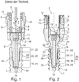
- Both pedicle screw systems which according to the prior art in FIG. 1 as well as according to the invention in FIG. 2 include a bone screw 1, a shaft head element 2, a receiving sleeve 3, also referred to as tulip 3 and a clamping punch 4th
- the receiving sleeve 3 is formed as a separate component and movably disposed on the shaft head element 2, so that a polyaxial pedicle screw system is formed, wherein the receiving sleeve 3 relative to the bone screw 1 and the Shank head element 2 angularly positionable, in particular rotatable and / or pivotable, is. It has a substantially cylindrical basic shape with in a through hole 5 in the longitudinal direction. The distal end region of the passage opening 5 is tapered in the radial direction in the manner of a spherical segment and forms a ball seat 34 for a ball head 6 of the shaft head element 2. Proximal is formed in the receiving sleeve 3, a receiving space 7 for a longitudinal carrier, not shown in the figures.
- the through hole 5 of the clamping punch 4 is arranged. He lies in the radial direction of the passage opening 5 surrounding sleeve wall and has at its distal end a part-spherical receiving surface 12 for clamping engagement on the ball head 6. Its proximal end is formed into an approximately half-shell-shaped bearing shell 13 for the longitudinal member. It has a central passage opening 14.
- the shaft head element 2 has the ball head 6 at its proximal end.
- the shaft head element 2 is also provided with a central passage opening 16 in the direction of the longitudinal axis.
- the bone screw 1 also has a central passage opening 17 in the direction of the longitudinal axis. At its radially outer side it is provided with a bone thread 18. In the proximal end region of the bone screw 1, the passage opening 17 is widened in the radial direction.
- a distal flared portion 19, a medial flared portion 20, and a proximal flared portion 21 are formed in the through hole 17.
- the medial expanded portion 20 is provided with a connecting thread 22.
- the inner diameter of the distal flared portion 19 is smaller than that of the medial flared portion 20, which in turn is smaller than that of the proximal flared portion 21. In other words, the inner diameter increases from distal to proximal.
- the prior art shaft head element 2 has a shaft 23 distally. This is stepped, with a distal shaft portion 24, a medial shaft portion 25 and a proximal shaft portion 26.
- the medial flared shaft portion 25 is provided with a connecting thread 27.
- the inner diameter of the distal flared stem portion 24 is smaller than that of the medial flared stem portion 25, which in turn is smaller than that of the proximal flared stem portion 26. In other words, the inner diameter increases from distal to proximal.
- the two connecting threads 22, 27 are threadedly engaged with each other and couple the bone screw 1 with the shaft head element 2.
- the bone screw 1 at the level of the transition from the medial expanded portion 20 to the distal expanded portion 19 due to the concentrated notch effect occurring there may preferentially break, since here, due to the bone thread, the wall thickness is very low and so that a large voltage jump is present.
- the bone screw 1 according to the invention, a distal flared portion 19 and a proximal flared portion 21 is formed in the through hole 17. Between these, however, a plurality of, in the present example, two medial expanded connecting thread sections are formed, namely a distal connecting thread section 28 and a proximal connecting thread section 29.
- the inner diameter of the distal flared portion 19 is smaller than that of the distal connecting thread portion 28, which in turn is smaller than that of the proximal connecting thread portion 29, which in turn is smaller than that of the proximal flared portion 21. In other words, the inner diameter increases from distal to proximal.
- the shaft head element 2 has a shaft 23 distally. This is stepped, with its distal shaft portion 24 and its proximal shaft portion 26. However, there are formed a plurality of, in the present example, two medial expanded connecting threaded shaft portions, namely a distal connecting threaded shaft portion 30 and a proximal connecting threaded shaft portion 31.
- the inner diameter of the distal shaft portion 24 is smaller than that of the distal connecting threaded shaft portion 30, which in turn is smaller than that of the proximal connecting threaded shaft portion 31, which in turn is smaller than that of the proximal shaft portion 26. In other words, the inner diameter increases from distal to proximal.
- the four connecting thread portions 28, 29, 30, 31 are threadedly engaged with each other, forming connecting threads 35 and 36, respectively, and coupling the bone screw 1 with the stem head member 2.
- the distal connecting thread portion 28 communicates with the distal connecting thread shaft portion 30 and the proximal connecting thread portion 29 with the proximal connecting threaded shaft portion 31 in threaded engagement.
- the shaft head element 2 can be inserted from proximal to distal through the receiving sleeve 3 and can then be screwed to the bone screw 1, so that it can be formed with almost any nominal diameter regardless of the geometry of the receiving sleeve 3.
- the bone screw 1 In the fully screwed state, the bone screw 1 abuts with its end face 32 against a stop 33 formed proximally of the proximal shaft section 26.
- the double-threaded connection 28, 29, 30, 31 causes the entire area between the distal connecting thread 28, 30 and the stop 33 to be subjected to compressive stress can be.
- This compressive stress causes a larger capacity in terms of recording of possibly acting biomechanical forces acting on the pedicle screw system.
- Under the proximal connection thread 28, 30, the screw would, as in the prior art with reference to the FIG. 1 described have a preferred failure point and there break preferably.
- notch effect can advantageously be reduced and minimized.
- the bone screw 1 has a Torxprofilingabrough 37 at its proximal flared portion 21.
- This Torxprofilingabrough 37 allows the revision of the bone screw 1, if the shaft head element 2 has separated from the bone screw 1.
Landscapes
- Health & Medical Sciences (AREA)
- Orthopedic Medicine & Surgery (AREA)
- Life Sciences & Earth Sciences (AREA)
- Surgery (AREA)
- Neurology (AREA)
- Heart & Thoracic Surgery (AREA)
- Engineering & Computer Science (AREA)
- Biomedical Technology (AREA)
- Nuclear Medicine, Radiotherapy & Molecular Imaging (AREA)
- Medical Informatics (AREA)
- Molecular Biology (AREA)
- Animal Behavior & Ethology (AREA)
- General Health & Medical Sciences (AREA)
- Public Health (AREA)
- Veterinary Medicine (AREA)
- Surgical Instruments (AREA)
Description
- Die vorliegende Erfindung betrifft ein Pedikelschraubensystem umfassend eine Aufnahmehülse für einen Längsträger, eine Knochenschraube und ein Schaftkopfelement, wobei die Knochenschraube ein als Außengewinde ausgebildetes Knochengewinde und ein als Innengewinde ausgebildeten Verbindungsgewinde aufweist, wobei das Schaftkopfelement proximal (aus der Sicht des Chirurgen) einen Kopf, auf dem die Aufnahmehülse gelagert ist, und distal (aus der Sicht des Chirurgen) ein als Außengewinde ausgebildetes Verbindungsgewinde aufweist und damit in das Verbindungsgewinde der Knochenschraube eingeschraubt ist.
- Pedikelschrauben dienen prinzipiell zur dorsalen Stabilisierung der Wirbelsäule bei Fakturen, Tumoren, Entzündungen, Deformitäten und degenerativ bedingten Instabilitäten mittels transpedikulärer Verschraubung. Dabei werden Pedikelschrauben in den Pedikeln jeweils benachbarter Wirbel platziert, worauf eine winkelstabile Verbindung zwischen den jeweils axial übereinander sich anordnenden Pedikelschrauben und einem axial sich erstreckenden Längsträger oder Steg geschaffen wird. Die Pedikelschrauben und Längsträger bilden dabei ein Wirbel-Stabilisierungssystem.
- Hierfür hat eine Pedikelschraube in der Regel ein sich in axialer Richtung erstreckendes Außengewinde als Knochengewinde, an den sich schraubenkopfseitig eine Aufnahmehülse (sogenannte Tulpe) anschließt. Diese bildet konstruktiv eine U-förmig längs geschlitzte/getunnelte Aufnahme mit Innengewinde zur Aufnahme eines Längsträgers, wobei die beiden sich radial gegenüberliegenden Längsschlitze jeweils einen Schlitzspalt vorbestimmter Spaltbreite definieren. In die parallel zueinander verlaufenden Längsschlitze ist der Längsträger quer einlegbar und mittels eines Verriegelungselements, zum Beispiel in Form einer Madenschraube, Gewindemutter oder Setscrew, die in das Innengewinde eingedreht ist, fixierbar.
- Bei einer polyaxialen Pedikelschraube ist ein zumeist kugelförmiger oder (semi-) sphärischer Schaftkopf von der Aufnahmehülse/Tulpe relativ verschwenkbar umgriffen und gleichzeitig im Übergangsbereich zwischen Kopf und Schaft hintergriffen. Auf diese Weise kann die Aufnahmehülse/Tulpe nach Versenken des Außengewindeschafts im Pedikelkanal eines Wirbels relativ dazu verschwenkt und/oder verdreht werden, um eine gewünschte Lage und Ausrichtung im Wesentlichen unabhängig zur Ausrichtung des Schafts zu erhalten. Die Hinterschneidung verhindert dabei, dass die Aufnahmehülse/Tulpe vom Schaftkopf abgezogen werden kann.
- In der Praxis können Fälle auftreten, bei denen Pedikelschrauben mit einem Knochengewinde mit großem Durchmesser erforderlich sind. Insbesondere bei einer polyaxialen Pedikelschraube mit großen Knochenschraubendurchmesser kann problematisch sein, dass der maximal mögliche Knochenschraubendurchmesser durch die Geometrie und die Abmessungen der Aufnahmehülse bestimmt und begrenzt ist. Konstruktionsbedingt ist aber die Knochenschraube von proximal nach distal durch die Aufnahmehülse hindurchzuführen, so dass ihr Schaftkopf gelagert in der Aufnahmehülse zu liegen kommt. Grund ist hierbei die Forderung nach einem möglichst kleinen Kopfteil bzw. einer möglichst kleinen Aufnahmehülse und dem sich daraus ergebenden kleinen Innendurchmesser der Aufnahmehülse.
- Gattungsgemäßer Stand der Technik ist etwa aus der
DE 10 2004 027 881 A1 bekannt. Diese offenbart eine Knochenschraube mit einem im Wesentlichen einheitlichen Verbindungsgewindeabschnitt. Vergleichbare Vorrichtungen sind aus derUS 2008 / 0015596 A1 , derGB 2512063 A US 2012 / 0215263 A1 bekannt. - Um das vorstehend beschriebene Problem zu lösen, wurde vom Anmelder dieser Erfindung bereits ein Design für eine mehrteilige Pedikelschraube entwickelt, welches eine Knochenschraube und ein Schaftkopfelement aufweist. Die Knochenschraube weist ein als Außengewinde ausgebildetes Knochengewinde und ein als Innengewinde ausgebildeten Verbindungsgewinde auf. Das Schaftkopfelement weist wiederum proximal einen Kopf zur Lagerung der Aufnahmehülse und distal ein als Außengewinde ausgebildetes Verbindungsgewinde auf. Das Schaftkopfelement und die Knochenschraube sind über die Verbindungsgewinde miteinander verbunden. Durch diese zweiteilige Ausführung wird der Vorteil erzielt, dass das Schaftkopfelement auf die Abmessungen der Aufnahmehülse abgestimmt ausgebildet sein kann, also derart, dass es durch diese von proximal nach distal bis zum Anschlag am Schaftkopf hindurchgeführt werden kann, während die Knochenschraube aus distaler Richtung, ohne durch die Aufnahmehülse hindurch geführt werden zu müssen, auf das in die Aufnahmehülse vormontierte Schaftkopfelement aufgeschraubt werden kann und hinsichtlich seines Knochengewindedurchmesser nicht beschränkt ist.
- Ein mögliches Problem bei dieser mehrteiligen Pedikelschraube kann in bestimmten Fällen sein, dass das Knochengewinde im Bereich der Verschraubung von Knochenschraube und Schaftkopfelement, also im Bereich der Verbindungsverschraubung, sehr flach und konisch vorgesehen werden muss, um eine ausreichende Stabilität der Knochenschraube sicherzustellen und um die Wahrscheinlichkeit eines Bruchs der Knochenschraube infolge der dünnen Wand zwischen dem Knochengewinde und dem Verbindungsgewinde begünstigt durch deren hohe Kerbwirkungen vermindern bzw. verhindern zu können. Es gibt jedoch Anwendungen, bei denen darauf Wert gelegt wird, dass die Knochenschraube an Stelle von einem konischen Gewindekern einen zylindrischen oder annähernd zylindrischen Gewindekern aufweist.
- Ausgehend vom vorgenannten Stand der Technik liegt der Erfindung die Aufgabe zugrunde, ein Pedikelschraubensystem bereit zu stellen, das bei gleichem Außendurchmesser, gleicher Eindrehfestigkeit, gleicher Ausdrehfestigkeit und gleicher biomechanischen Dauerfestigkeit einen zylindrischen oder annähernd zylindrischen Gewindekern aufweist. Insbesondere soll eine möglichst große Gewindetiefe des Knochengewindes vorgesehen sein. Es soll eine Übertragung von Eindrehmomenten ≥ 12 Nm und eine Übertragung von Ausdrehmomenten ≥ 10 Nm möglich sein. Bei einem Versagen, insbesondere bei einem Bruch des Implantats, bei einer Revision oder bei einer ungewollten intraoperativen Demontage des Implantats soll ein Ausschrauben des Knochengewindeteils aus dem Knochen ohne wesentliche Probleme möglich sein. Schließlich ist zwischen der Knochenschraube und dem Schaftkopfelement eine dichte Verbindung erforderlich, um eine ausreichende Reinigungseignung zu gewährleisten.
- Diese Aufgabe wird nach der vorliegenden Erfindung gelöst durch ein Pedikelschraubensystem nach dem Oberbegriff von Anspruch 1, wobei die Verbindungsgewinde jeweils als (vorzugsweise ausgerichtete / gleichlaufende) Mehrfachgewinde mit jeweils einem distalen Verbindungsgewindeabschnitt und einem proximalen Verbindungsgewindeabschnitt ausgebildet sind. Der distale Verbindungsgewindeabschnitt und der proximale Verbindungsgewindeabschnitt weisen eine identische oder gleiche Gewindesteigung auf. Der distale Verbindungsgewindeabschnitt besitzt einen kleineren Durchmesser, insbesondere einen kleineren Nenndurchmesser, als der proximale Verbindungsgewindeabschnitt.
- Mittels der unterschiedlich großen Durchmesser des distalen Verbindungsgewindeabschnitts (klein / gering) und des proximalen Verbindungsgewindeabschnitts (groß / weit) werden die folgenden, gegenläufigen Effekte erreicht: Zum einen mindert der geringe distale Verbindungsgewindeabschnitt die auf den Knochen wirkende Kerbwirkung. Dies ermöglicht der Schraube, einer hohen Zugwiderstandskraft / "Pull-Out-Kraft" entgegenwirken zu können. Zum anderen ist mittels des weiten proximalen Verbindungsgewindeabschnitts eine erhöhte Momentenbelastung der Schraube möglich, welche ein gesteigertes Einstellmoment zulässt.
- Um eine sichere, stabile und dauerhafte Verbindung von Knochenschraube und Schaftkopfelement sicherstellen zu können, ist eine bestimmte Länge des Verbindungsgewindes erforderlich. Nach der der Erfindung zugrunde liegenden Idee wird das Verbindungsgewinde zwischen Knochenschraube und Schaftkopfelement bekannter Pedikelschraubensysteme quasi in mehrere Gewindeabschnitte aufgeteilt. Deren Gewindedurchmesser, insbesondere Nenndurchmesser, unterscheiden sich jeweils voneinander. Proximale Verbindungsgewindeabschnitte besitzen einen größeren Durchmesser (Nenndurchmesser) als distale Verbindungsgewindeabschnitte. Man kann also sagen, dass die Durchmesser der Verbindungsgewindeabschnitte von proximal nach distal kleiner werden. Ein weiterer dadurch bewirkter Effekt ist, dass sich die Wandstärke der Knochenschraube im Bereich der Verbindungsgewinde stufenweise ändert, und zwar in mehreren gegenüber den Stand der Technik kleineren Schritten (dort gibt es am Verbindungsgewindeauslauf eine relativ große Querschnittsänderung mit entsprechender Kerbwirkung). Dadurch kann zum einen die am Ende des Verbindungsgewindes, insbesondere am distalen Verbindungsgewindeauslauf, auftretende Kerbwirkung gegenüber den Stand der Technik minimiert werden. Zum anderen wird die Kerbwirkung durch Vorsehen mehrerer Verbindungsgewindeausläufe, nämlich an jedem Verbindungsgewindeabschnitt, auf einen größeren Abschnitt der Knochenschraube in Längsrichtung verteilt, nämlich auf die gesamte Länge des Verbindungsgewindes. Insgesamt können durch die Erfindung die im Bereich des Verbindungsgewindes auf die Knochenschraube wirkenden Belastungen und eingebrachten Spannungen gegenüber dem Stand der Technik bei gleicher Gewindelänge wesentlich reduziert werden. Das erfindungsgemäße Pedikelschraubensystem kann daher bei gleichem Außendurchmesser, gleicher Eindrehfestigkeit, gleicher Ausdrehfestigkeit und gleicher biomechanischen Dauerfestigkeit mit (im Wesentlichen) zylinderförmigem Knochengewindekern ausgebildet werden.
- Zur Klarstellung sei überdies erwähnt, dass eine "identische Gewindesteigung" des proximalen und distalen Verbindungsgewindeabschnitts im Sinne der Erfindung bedeutet, dass sich diese in ihrer Steigung nicht mehr als 10% zueinander unterscheiden, sodass die daraus (möglicherweise) resultierende Abweichung tolerabel ist, das heißt dass die Schraube bei jenen geringen Abweichungen eindrehbar bleibt.
- Vorteilhafte Ausführungsformen der Erfindung sind in den Unteransprüchen beansprucht und werden nachfolgend näher erläutert.
- Eine Ausführungsform der Erfindung ist dadurch gekennzeichnet, dass die Verbindungsgewinde der Knochenschraube als Doppelgewinde ausgebildet sind. Dieses weist einen ersten, distalen Verbindungsgewindeabschnitt und einen zweiten, proximalen Verbindungsgewindeabschnitt auf. Des Weiteren sind die Verbindungsgewinde des Schaftkopfelements als Doppelgewinde ausgebildet, ebenfalls mit einem ersten, distalen Verbindungsgewindeabschnitt und einem zweiten, proximalen Verbindungsgewindeabschnitt.
- Alternativ oder zusätzlich können der Gewindedurchmesser und die Gewindesteigung jedes Verbindungsgewindeabschnitts jeweils konstant sein.
- Es ist von besonderem Vorteil, wenn das Schaftkopfelement einen Anschlag aufweist, an dem eine Anschlagfläche der Knochenschraube, insbesondere deren proximale Stirnfläche anliegt, wenn das Schaftkopfelement und die Knochenschraube über ihre jeweiligen Verbindungsgewinde vollständig miteinander verschraubt sind. Das nach der Erfindung genutzte Mehrfachgewinde bewirkt gemeinsam mit dem Anschlag, dass die Knochenschraube im gesamten Bereich zwischen dem distalen Verbindungsgewinde und Anschlag unter Druckspannung gebracht wird. Diese Druckspannung bewirkt eine größere Kapazität hinsichtlich einer Aufnahme von die Knochenschraube wirkenden biomechanischen Kräften. Das Schaftkopfelement und die Knochenschraube können am Anschlag insbesondere dichtend aneinander anliegen, so dass das Verbindungsgewinde nicht verschmutzt und gut zu reinigen ist.
- Eine Ausführungsform der Erfindung ist dadurch gekennzeichnet, dass die Knochenschraube eine sich in Richtung der Längsachse erstreckende zentrale, gestufte Öffnung aufweist, insbesondere in Form einer Sackbohrung oder einer Durchgangsbohrung. Die Öffnung kann mehrere Abschnitte aufweisen, deren Anzahl zumindest der Anzahl der Verbindungsgewindeabschnitte entspricht, wobei die Abschnitte zueinander unterschiedliche Innendurchmesser besitzen. Eine solche zentrale Öffnung erleichtert das Einschrauben des Schaftkopfelements in die Knochenschraube. Im Falle einer Durchgangsöffnung kann diese zum Beispiel genutzt werden, um eine Knochenverbindungsmaterial, zum Beispiel Knochenzement, durch die Schraube an den Knochen zu bringen.
- Eine Ausführungsform der Erfindung ist dadurch gekennzeichnet, dass die zentrale Öffnung der Knochenschraube einen proximalen gewindelosen Abschnitt und distalen gewindelosen Abschnitt aufweist, zwischen denen der distale Verbindungsgewindeabschnitt und der proximale Verbindungsgewindeabschnitt angeordnet sind. Solche gewindelosen Abschnitte können in vorteilhafter Weise als Positionierungshilfen verwendet werden und erleichtern das Setzen der Pedikelschraube durch einen Operateur.
- Nach einer Ausführungsform der Erfindung ist vorgesehen, dass das Schaftkopfelement einen gestuften Zapfen aufweist, mit einem proximalen gewindelosen Abschnitt und einem distalen gewindelosen Abschnitt, zwischen denen der distale Verbindungsgewindeabschnitt und der proximale Verbindungsgewindeabschnitt angeordnet sind.
- Es ist von besonderem Vorteil, wenn der distale gewindelose Abschnitt einen kleineren Durchmesser aufweist als der distale Verbindungsgewindeabschnitt und dass der proximale gewindelose Abschnitt einen größeren Durchmesser aufweist als der proximale Verbindungsgewindeabschnitt. Hierdurch kann Kerbwirkung infolge von Querschnittänderungen reduziert oder gering gehalten werden.
- Eine weitere Ausführungsform der Erfindung ist dadurch gekennzeichnet, dass das Knochengewinde einen zylinderförmigen oder im Wesentlichen oder annähernd zylinderförmigen Gewindekern mit im Wesentlichen konstantem Kerndurchmesser aufweist. Ein solches Knochengewinde sichert einen guten Halt der Knochenschraube im Knochen und eine gleichmäßige Lasteinbringung über die gesamte Länge des Knochengewindes in das Knochenmaterial. Eine weitere Ausführungsform der Erfindung ist dadurch gekennzeichnet, dass die Gewindetiefe des Knochengewindes im Bereich der Verbindungsgewinde konstant ist.
- Nach einer Ausführungsform kann der proximale gewindelose Abschnitt einen Torxprofilaufnahmeabschnitt zur Aufnahme eines Torxschraubendrehers aufweisen, um eine Revision der Knochenschraube zu ermöglichen, falls sich das Schaftkopfelement von der Knochenschraube gelöst hat, oder ein unmittelbares (nicht über das Schaftkopfelement) Einschrauben oder Herausschrauben der Knochenschraube zu ermöglich.
- In einer alternativen Ausführungsform ist der proximale Verbindungsgewindeabschnitt zum distalen Verbindungsgewindeabschnitt innerhalb eines gewissen Toleranzbereichs in der Umfangsrichtung der Schraube versetzt. Hieraus resultiert beim Einschrauben der Schraube eine gewisse Verspannung, welche das Festsitzen / die aufzubringende Pull-Out-Kraft (ebenso wie etwaige Abweichungen in der Gewindesteigung) der Schraube begünstigt.
- Zusammenfassend kann man sagen, dass durch die Erfindung eine zweiteilige Knochenschraube ermöglicht wird, welche zwei oder mehrere Gewindeabschnitte aufweist, welche zueinander (im Wesentlichen) ausgerichtet sind und die (im Wesentlichen) gleiche Gewindesteigung aufweisen. Der Gewindedurchmesser kann hierbei von vorne nach hinten abnehmen. Man kann insbesondere sagen, dass durch die Erfindung ein polyaxiales Pedikelschraubensystem mit mehrteiliger, insbesondere zweiteiliger, Knochenschraube ermöglicht wird, bei dem die Knochenschraube bei gleichem Außendurchmesser wie eine Knochenschraube mit konischem Knochengewinde nach dem Stand der Technik ein im Wesentlichen zylindrisches Gewindekernprofil mit ausgeprägter Gewindetiefe aufweist.
- Weitere Merkmale und Vorteile der vorliegenden Erfindung ergeben sich aus der folgenden beispielhaften und nicht beschränkenden Beschreibung der Erfindung anhand von Figuren. Diese sind lediglich schematischer Natur und dienen nur dem Verständnis der Erfindung. Dabei zeigen:
-
Fig. 1 in einer schematischen Schnittdarstellung ein Pedikelschraubensystem nach dem Stand der Technik und -
Fig. 2 in einer schematischen Schnittdarstellung ein Pedikelschraubensystem nach der Erfindung. - Beide Pedikelschraubensysteme, das nach dem Stand der Technik in
Figur 1 wie auch das nach der Erfindung inFigur 2 , umfassen eine Knochenschraube 1, ein Schaftkopfelement 2, eine Aufnahmehülse 3, auch als Tulpe 3 bezeichnet und einen Klemmstempel 4. - Die Aufnahmehülse 3 ist als gesondertes Bauteil ausgebildet und beweglich am Schaftkopfelement 2 angeordnet, so dass ein polyaxiales Pedikelschraubensystem ausgebildet ist, bei dem die Aufnahmehülse 3 relativ zur Knochenschraube 1 und zum Schaftkopfelement 2 winkelpositionierbar, insbesondere drehbar und/oder schwenkbar, ist. Sie weist eine im Wesentlichen zylinderförmige Grundgestalt mit in einer Durchgangsöffnung 5 in Längsrichtung auf. Der distale Endbereich der Durchgangsöffnung 5 ist sich in radialer Richtung kugelabschnittsförmig nach innen verjüngend ausgebildet und bildet eine Kugelaufnahme 34 für einen Kugelkopf 6 des Schaftkopfelements 2 aus. Proximal ist in der Aufnahmehülse 3 ein Aufnahmeraum 7 für einen in den Figuren nicht dargestellten Längsträger ausgebildet. Dieser ist seitlich von zwei radial einander gegenüberliegenden Hülsenwandabschnitten 8, 9 auf, in deren einander zugewandten Innenflächen ein Innengewinde 10 eingebracht ist. Dieses dient der Aufnahme einer in den Figuren ebenfalls nicht gezeigten Klemmschraube, zum Beispiel in Form einer üblichen Madenschraube. In die Außenseiten der Hülsenwandabschnitte 8, 9 ist jeweils eine Werkzeugaufnahme 11 eingebracht, zur Aufnahme und Kopplung eines medizintechnischen Instruments zum Handhaben der Aufnahmehülse 3 oder des gesamten Pedikelschraubensystems.
- In der Durchgangsöffnung 5 ist der Klemmstempel 4 angeordnet. Er liegt in radialer Richtung an der die Durchgangsöffnung 5 umgebenden Hülsenwandung an und weist an seinem distalen Ende eine teilkugelförmige Aufnahmefläche 12 zur klemmenden Anlage am Kugelkopf 6 auf. Sein proximales Ende ist zu einer etwa halbschalenförmigen Lagerschale 13 für den Längsträger ausgebildet. Er weist eine zentrale Durchgangsöffnung 14 auf.
- Das Schaftkopfelement 2 weist an seinem proximalen Ende den Kugelkopf 6 auf. In diesen ist eine Werkzeugaufnahme 15, hier in Form eines Innensechskants, eingebracht. Auch das Schaftkopfelement 2 ist mit einer zentralen Durchgangsöffnung 16 in Richtung der Längsachse versehen.
- Die Knochenschraube 1 weist ebenfalls eine zentrale Durchgangsöffnung 17 in Richtung der Längsachse auf. An ihrer radial äußeren Seite ist sie mit einem Knochengewinde 18 versehen. In den proximalen Endbereich der Knochenschraube 1 ist die Durchgangsöffnung 17 in radialer Richtung aufgeweitet.
- Bei der Knochenschraube 1 nach dem Stand der Technik ist in der Durchgangsöffnung 17 ein distaler aufgeweiteter Abschnitt 19, ein medialer aufgeweiteter Abschnitt 20 und ein proximaler aufgeweiteter Abschnitt 21 ausgebildet. Der mediale aufgeweitete Abschnitt 20 ist mit einem Verbindungsgewinde 22 versehen. Der Innendurchmesser des distalen aufgeweiteten Abschnitts 19 ist kleiner als der des medialen aufgeweiteten Abschnitts 20, der wiederum kleiner ist als der des proximalen aufgeweiteten Abschnitts 21. Anders ausgedrückt steigt der Innendurchmesser von distal nach proximal an. Das Schaftkopfelement 2 nach dem Stand der Technik weist distal einen Schaft 23 auf. Dieser ist gestuft ausgebildet, mit einem distalen Schaftabschnitt 24, einem medialen Schaftabschnitt 25 und einem proximalen Schaftabschnitt 26. Der mediale aufgeweitete Schaftabschnitt 25 ist mit einem Verbindungsgewinde 27 versehen. Der Innendurchmesser des distalen aufgeweiteten Schaftabschnitts 24 ist kleiner als der des medialen aufgeweiteten Schaftabschnitts 25, der wiederum kleiner ist als der des proximalen aufgeweiteten Schaftabschnitts 26. Anders ausgedrückt steigt der Innendurchmesser von distal nach proximal an. Die beiden Verbindungsgewinde 22, 27 stehen miteinander in Gewindeeingriff und koppeln die Knochenschraube 1 mit dem Schaftkopfelement 2. Durch diese Konstruktion ist das Schaftkopfelement 2 von proximal nach distal durch die Aufnahmehülse 3 einsetzbar und kann dann mit der Knochenschraube 1 verschraubt werden, so dass diese mit nahezu beliebigem Nenndurchmesser unabhängig von der Geometrie der Aufnahmehülse 3 ausgebildet sein kann. Nachteil der in
Figur 1 gezeigten Version nach dem Stand der Technik ist, dass die Knochenschraube 1 in Höhe des Übergangs vom medialen aufgeweiteten Abschnitt 20 zum distalen aufgeweiteten Abschnitt 19 infolge der dort konzentriert auftretenden Kerbwirkung bevorzugt brechen kann, da hier, bedingt durch das Knochengewinde die Wandstärke sehr gering ist und damit ein großer Spannungssprung vorhanden ist. - Dieses Problem wird durch die Erfindung gelöst, die in
Figur 2 gezeigt ist. Auch die Knochenschraube 1 nach der Erfindung ist in der Durchgangsöffnung 17 ein distaler aufgeweiteter Abschnitt 19 und ein proximaler aufgeweiteter Abschnitt 21 ausgebildet. Zwischen diesen sind jedoch mehrere, im vorliegenden Beispiel zwei mediale aufgeweitete Verbindungsgewindeabschnitte ausgebildet, nämlich ein distaler Verbindungsgewindeabschnitt 28 und ein proximaler Verbindungsgewindeabschnitt 29. Der Innendurchmesser des distalen aufgeweiteten Abschnitts 19 ist kleiner als der des distalen Verbindungsgewindeabschnitts 28, der wiederum kleiner ist als der des proximalen Verbindungsgewindeabschnitts 29, der wiederum kleiner ist als der des proximalen aufgeweiteten Abschnitts 21. Anders ausgedrückt steigt der Innendurchmesser von distal nach proximal an. - Das Schaftkopfelement 2 nach der Erfindung weist distal einen Schaft 23 auf. Dieser ist gestuft ausgebildet, mit seinem distalen Schaftabschnitt 24 und seinem proximalen Schaftabschnitt 26. Zwischen diesen sind jedoch mehrere, im vorliegenden Beispiel zwei mediale aufgeweitete Verbindungsgewindeschaftabschnitte ausgebildet, nämlich ein distaler Verbindungsgewindeschaftabschnitt 30 und ein proximaler Verbindungsgewindeschaftabschnitt 31. Der Innendurchmesser des distalen Schaftabschnitts 24 ist kleiner als der des distalen Verbindungsgewindeschaftabschnitts 30, der wiederum kleiner ist als der des proximalen Verbindungsgewindeschaftabschnitts 31, der wiederum kleiner ist als der des proximalen Schaftabschnitts 26. Anders ausgedrückt steigt der Innendurchmesser von distal nach proximal an.
- Die insgesamt vier Verbindungsgewindeabschnitte 28, 29, 30, 31 stehen miteinander in Gewindeeingriff, bilden Verbindungsgewinde 35 bzw. 36 aus und koppeln die Knochenschraube 1 mit dem Schaftkopfelement 2. Genauer gesagt steht der distale Verbindungsgewindeabschnitt 28 mit dem distalen Verbindungsgewindeschaftabschnitt 30 und der proximale Verbindungsgewindeabschnitt 29 mit dem proximalen Verbindungsgewindeschaftabschnitt 31 in Gewindeeingriff. Durch diese Konstruktion ist das Schaftkopfelement 2 von proximal nach distal durch die Aufnahmehülse 3 einsetzbar und kann dann mit der Knochenschraube 1 verschraubt werden, so dass diese mit nahezu beliebigem Nenndurchmesser unabhängig von der Geometrie der Aufnahmehülse 3 ausgebildet sein kann. Im vollständig verschraubten Zustand liegt die Knochenschraube 1 mit ihrer Stirnseite 32 an einem proximal des proximalen Schaftabschnitts 26 ausgebildeten Anschlag 33 an. Das Doppelverbindungsgewinde 28, 29, 30, 31 bewirkt, dass der gesamte Bereich zwischen dem distalen Verbindungsgewinde 28, 30 und dem Anschlag 33 unter Druckspannung gebracht werden kann. Diese Druckspannung bewirkt eine größere Kapazität hinsichtlich einer Aufnahme von ggf. wirkenden biomechanischen, auf das Pedikelschraubensystem wirkenden Kräften. Unter das proximale Verbindungsgewinde 28, 30 würde die Schraube wie vorstehend bei Stand der Technik anhand der
Figur 1 beschrieben eine bevorzugte Versagensstelle aufweisen und dort bevorzugt brechen. Durch die erfindungsgemäße mehrfache, feinere Abstufung der Durchmesser kann Kerbwirkung in vorteilhafter Weise reduziert und minimiert werden. - Die Knochenschraube 1 weist an ihrem proximalen aufgeweiteten Abschnitt 21 einen Torxprofilaufnahmeabschnitt 37 auf. Dieser Torxprofilaufnahmeabschnitt 37 ermöglicht die Revision der Knochenschraube 1, falls sich das Schaftkopfelement 2 von der Knochenschraube 1 getrennt hat.
-
- 1
- Knochenschraube
- 2
- Schaftkopfelement
- 3
- Aufnahmehülse
- 4
- Klemmstempel
- 5
- Durchgangsöffnung
- 6
- Kugelkopf
- 7
- Aufnahmeraum
- 8
- Hülsenwandabschnitt
- 9
- Hülsenwandabschnitt
- 10
- Innengewinde
- 11
- Werkzeugaufnahme
- 12
- Aufnahmefläche
- 13
- Lagerschale
- 14
- Durchgangsöffnung
- 15
- Werkzeugaufnahme
- 16
- Durchgangsöffnung
- 17
- Durchgangsöffnung
- 18
- Knochengewinde
- 19
- distaler aufgeweiteter Abschnitt
- 20
- medialer aufgeweiteter Abschnitt
- 21
- proximaler aufgeweiteter Abschnitt
- 22
- Verbindungsgewinde (der Knochenschraube)
- 23
- Schaft, Zapfen
- 24
- distaler Schaftabschnitt
- 25
- medialer Schaftabschnitt
- 26
- proximaler Schaftabschnitt
- 27
- Verbindungsgewinde (des Schaftkopfelements)
- 28
- distaler Verbindungsgewindeabschnitt (der Knochenschraube)
- 29
- proximaler Verbindungsgewindeabschnitt (der Knochenschraube)
- 30
- distaler Verbindungsgewindeschaftabschnitt (des Schaftkopfelements)
- 31
- proximaler Verbindungsgewindeschaftabschnitt (des Schaftkopfelements)
- 32
- Stirnseite
- 33
- Anschlag
- 34
- Kugelaufnahme
- 35
- Verbindungsgewinde
- 36
- Verbindungsgewinde
- 37
- Torxprofilaufnahmeabschnitt
Claims (11)
- Pedikelschraubensystem mit einer Aufnahmehülse (3) für einen Längsträger, einer Knochenschraube (1) und einem Schaftkopfelement (2),
wobei die Knochenschraube (1) ein als Außengewinde ausgebildetes Knochengewinde (18) und ein als Innengewinde ausgebildeten Verbindungsgewinde (22) aufweist, und
wobei das Schaftkopfelement (2) proximal einen Kopf (6), auf dem die Aufnahmehülse (3) gelagert ist, und distal ein als Außengewinde ausgebildetes Verbindungsgewinde (27) aufweist und damit in das Verbindungsgewinde (22) der Knochenschraube (1) eingeschraubt ist,
dadurch gekennzeichnet, dass
die Verbindungsgewinde (22, 27) jeweils als Mehrfachgewinde mit jeweils einem distalen Verbindungsgewindeabschnitt (28, 30) und einem proximalen Verbindungsgewindeabschnitt (29, 31) ausgebildet sind, wobei
der distale Verbindungsgewindeabschnitt (28, 30) und der proximale Verbindungsgewindeabschnitt (29, 31) eine identische Gewindesteigung aufweisen; und der distale Verbindungsgewindeabschnitt (28, 30) einen kleineren Durchmesser als der proximale Verbindungsgewindeabschnitt (29, 31) aufweist. - Pedikelschraubensystem nach Anspruch 1, dadurch gekennzeichnet, dass die Verbindungsgewinde der Knochenschraube (1) als Doppelgewinde ausgebildet sind, mit einem ersten, distalen Verbindungsgewindeabschnitt (28) und einem zweiten, proximalen Verbindungsgewindeabschnitt (29), und die Verbindungsgewinde des Schaftkopfelements (2) als Doppelgewinde ausgebildet sind, mit einem ersten, distalen Verbindungsgewindeabschnitt (30) und einem zweiten, proximalen Verbindungsgewindeabschnitt (31).
- Pedikelschraubensystem nach Anspruch 1 oder 2, dadurch gekennzeichnet, dass der Gewindedurchmesser und die Gewindesteigung jedes Verbindungsgewindeabschnitts (28, 29, 30, 31) jeweils konstant sind.
- Pedikelschraubensystem nach einem der vorstehenden Ansprüche, dadurch gekennzeichnet, dass das Schaftkopfelement (2) einen Anschlag (33) aufweist, an dem eine Anschlagfläche der Knochenschraube (1), insbesondere deren proximale Stirnfläche (32) anliegt, wenn das Schaftkopfelement (2) und die Knochenschraube (1) über ihre jeweiligen Verbindungsgewinde (28, 29, 30, 31) vollständig miteinander verschraubt sind.
- Pedikelschraubensystem nach einem der vorstehenden Ansprüche, dadurch gekennzeichnet, dass die Knochenschraube (1) eine sich in Richtung der Längsachse erstreckende zentrale, gestufte Öffnung (17) aufweist, insbesondere in Form einer Sackbohrung oder einer Durchgangsbohrung (17), mit Abschnitten (19, 21, 28, 29) unterschiedlichen Innendurchmessers.
- Pedikelschraubensystem nach Anspruch 5, dadurch gekennzeichnet, dass die zentrale Öffnung (17) der Knochenschraube (1) einen proximalen gewindelosen oder mit einem Torxinnenprofil (37) versehenen Abschnitt (21) und distalen gewindelosen Abschnitt (19) aufweist, zwischen denen der distale Verbindungsgewindeabschnitt (28) und der proximale Verbindungsgewindeabschnitt (29) angeordnet sind.
- Pedikelschraubensystem nach einem der vorstehenden Ansprüche, dadurch gekennzeichnet, dass das Schaftkopfelement (2) einen gestuften Zapfen (23) aufweist, mit einem proximalen gewindelosen Abschnitt (26) und einem distalen gewindelosen Abschnitt (24), zwischen denen der distale Verbindungsgewindeabschnitt (30) und der proximale Verbindungsgewindeabschnitt (31) angeordnet sind.
- Pedikelschraubensystem nach Anspruch 6 oder 7, dadurch gekennzeichnet, dass der distale gewindelose Abschnitt (24) einen kleineren Durchmesser aufweist als der distale Verbindungsgewindeabschnitt (30) und dass der proximale gewindelose Abschnitt (26) einen größeren Durchmesser aufweist als der proximale Verbindungsgewindeabschnitt (31).
- Pedikelschraubensystem nach einem der vorstehenden Ansprüche, dadurch gekennzeichnet, dass das Schaftkopfelement (2) eine sich in Richtung der Längsachse erstreckende zentrale Öffnung (16) aufweist, insbesondere in Form einer Durchgangsbohrung (16).
- Pedikelschraubensystem nach einem der vorstehenden Ansprüche, dadurch gekennzeichnet, dass das Knochengewinde (18) einen zylinderförmigen Gewindekern mit im Wesentlichen konstantem Kerndurchmesser aufweist.
- Pedikelschraubensystem nach einem der vorstehenden Ansprüche, dadurch gekennzeichnet, dass die Gewindetiefe des Knochengewindes (18) im Bereich der Verbindungsgewinde (28, 29) konstant ist.
Applications Claiming Priority (2)
| Application Number | Priority Date | Filing Date | Title |
|---|---|---|---|
| DE102016108972.9A DE102016108972A1 (de) | 2016-05-13 | 2016-05-13 | Pedikelschraube mit Knochengewinde von großem Durchmesser |
| PCT/EP2017/061232 WO2017194633A1 (de) | 2016-05-13 | 2017-05-10 | Pedikelschraube mit knochengewinde von grossem durchmesser |
Publications (2)
| Publication Number | Publication Date |
|---|---|
| EP3288475A1 EP3288475A1 (de) | 2018-03-07 |
| EP3288475B1 true EP3288475B1 (de) | 2018-10-31 |
Family
ID=58699142
Family Applications (1)
| Application Number | Title | Priority Date | Filing Date |
|---|---|---|---|
| EP17722778.2A Active EP3288475B1 (de) | 2016-05-13 | 2017-05-10 | Pedikelschraube mit knochengewinde von grossem durchmesser |
Country Status (7)
| Country | Link |
|---|---|
| US (1) | US10335217B2 (de) |
| EP (1) | EP3288475B1 (de) |
| JP (1) | JP6522866B1 (de) |
| CN (1) | CN109152595B (de) |
| DE (1) | DE102016108972A1 (de) |
| ES (1) | ES2706575T3 (de) |
| WO (1) | WO2017194633A1 (de) |
Families Citing this family (22)
| Publication number | Priority date | Publication date | Assignee | Title |
|---|---|---|---|---|
| US20060200044A1 (en) | 2002-04-19 | 2006-09-07 | Pelikan Technologies, Inc. | Method and apparatus for measuring analytes |
| US20180228621A1 (en) | 2004-08-09 | 2018-08-16 | Mark A. Reiley | Apparatus, systems, and methods for the fixation or fusion of bone |
| US10363140B2 (en) | 2012-03-09 | 2019-07-30 | Si-Bone Inc. | Systems, device, and methods for joint fusion |
| US11147688B2 (en) | 2013-10-15 | 2021-10-19 | Si-Bone Inc. | Implant placement |
| EP2932929B1 (de) * | 2014-04-15 | 2017-02-08 | Biedermann Technologies GmbH & Co. KG | Schraubelement zur Verwendung in der spinalen, orthopädischen oder traumatologischen Chirurgie und System mit solch einem Schraubelement und daran angepassten Schraubendreher |
| EP3503827A4 (de) | 2016-08-24 | 2020-08-05 | Integrity Implants Inc. | Verstellbare knochenfixationssysteme |
| EP3687422A4 (de) | 2017-09-26 | 2021-09-22 | SI-Bone, Inc. | Systeme und verfahren zur dekortikation des iliosakralgelenks |
| US20190298528A1 (en) | 2018-03-28 | 2019-10-03 | Derek P. LINDSEY | Threaded implants and methods of use across bone segments |
| US11490932B2 (en) * | 2018-11-01 | 2022-11-08 | Next Orthosurgical, Inc. | Polyaxial pedicle screw system |
| CA3122995C (en) * | 2018-12-12 | 2025-06-03 | Orthopediatrics Corp. | BONE ANCHOR HEAD EXTENSION DEVICE |
| US11369419B2 (en) | 2019-02-14 | 2022-06-28 | Si-Bone Inc. | Implants for spinal fixation and or fusion |
| EP4613244A3 (de) | 2019-02-14 | 2025-11-12 | SI-Bone Inc. | Implantate zur wirbelsäulenfixierung und/oder -fusion |
| US11083501B2 (en) * | 2019-04-24 | 2021-08-10 | Warsaw Orthopedic, Inc. | Surgical system and method |
| AU2020386985A1 (en) | 2019-11-21 | 2022-06-02 | Si-Bone Inc. | Rod coupling assemblies for bone stabilization constructs |
| WO2021108590A1 (en) | 2019-11-27 | 2021-06-03 | Si-Bone, Inc. | Bone stabilizing implants and methods of placement across si joints |
| JP2023504571A (ja) | 2019-12-09 | 2023-02-03 | エスアイ-ボーン・インコーポレイテッド | 仙腸関節安定化インプラント及び埋込方法 |
| JP7440648B2 (ja) * | 2020-01-30 | 2024-02-28 | ネクスト オーソサージカル,インク. | 多軸椎弓根スクリューシステム |
| US20230248482A1 (en) * | 2020-10-14 | 2023-08-10 | Move Dental Ltd | Dental and orthopedic fastener with directional shock absorber |
| JP2023553120A (ja) | 2020-12-09 | 2023-12-20 | エスアイ-ボーン・インコーポレイテッド | 仙腸関節安定化インプラントおよびインプラント方法 |
| EP4534036B1 (de) * | 2021-03-05 | 2026-05-13 | Medos International Sarl | Polyaxiale schraube mit mehreren merkmalen |
| WO2023102533A1 (en) | 2021-12-03 | 2023-06-08 | Si-Bone Inc. | Fusion cages and methods for sacro-iliac joint stabilization |
| AU2024325368A1 (en) | 2023-08-15 | 2026-03-12 | Si-Bone Inc. | Pelvic stabilization implants, methods of use and manufacture |
Family Cites Families (9)
| Publication number | Priority date | Publication date | Assignee | Title |
|---|---|---|---|---|
| IT1237496B (it) * | 1989-10-26 | 1993-06-08 | Giuseppe Vrespa | Dispositivo a vite per l'ancoraggio di protesi alle ossa, metodo per l'applicazione di tale dispositivo e relativa attrezzatura |
| JP4185458B2 (ja) * | 2001-12-04 | 2008-11-26 | ジンテーズ ゲゼルシャフト ミト ベシュレンクテル ハフツング | 骨ねじ |
| DE102004027881B4 (de) | 2004-05-28 | 2006-06-01 | Aesculap Ag & Co. Kg | Knochenschraube und Osteosynthesevorrichtung |
| US20080015596A1 (en) * | 2006-04-28 | 2008-01-17 | Whipple Dale E | Large diameter multiple piece bone anchor assembly |
| US8162990B2 (en) * | 2006-11-16 | 2012-04-24 | Spine Wave, Inc. | Multi-axial spinal fixation system |
| KR101093513B1 (ko) * | 2011-02-23 | 2011-12-14 | 이춘성 | 신장이 가능한 척추고정나사 |
| EP2713919B1 (de) * | 2011-05-26 | 2018-02-07 | Eisertech, LLC | Knochenschraubensystem mit einem verbindungsteil |
| DE102011109677B4 (de) * | 2011-08-08 | 2018-07-26 | Human Tech Germany Gmbh | Plattensystem zur zervikalen Stabilisation und Fixation |
| GB2512063B (en) * | 2013-03-18 | 2019-05-29 | Fitzbionics Ltd | Spinal implant assembly |
-
2016
- 2016-05-13 DE DE102016108972.9A patent/DE102016108972A1/de not_active Withdrawn
-
2017
- 2017-05-10 JP JP2018560008A patent/JP6522866B1/ja active Active
- 2017-05-10 ES ES17722778T patent/ES2706575T3/es active Active
- 2017-05-10 CN CN201780029683.5A patent/CN109152595B/zh active Active
- 2017-05-10 US US16/099,241 patent/US10335217B2/en active Active
- 2017-05-10 WO PCT/EP2017/061232 patent/WO2017194633A1/de not_active Ceased
- 2017-05-10 EP EP17722778.2A patent/EP3288475B1/de active Active
Non-Patent Citations (1)
| Title |
|---|
| None * |
Also Published As
| Publication number | Publication date |
|---|---|
| JP6522866B1 (ja) | 2019-05-29 |
| ES2706575T3 (es) | 2019-03-29 |
| WO2017194633A1 (de) | 2017-11-16 |
| CN109152595A (zh) | 2019-01-04 |
| EP3288475A1 (de) | 2018-03-07 |
| US20190133660A1 (en) | 2019-05-09 |
| US10335217B2 (en) | 2019-07-02 |
| JP2019516474A (ja) | 2019-06-20 |
| CN109152595B (zh) | 2020-01-17 |
| DE102016108972A1 (de) | 2017-11-16 |
Similar Documents
| Publication | Publication Date | Title |
|---|---|---|
| WO2017194633A1 (de) | Pedikelschraube mit knochengewinde von grossem durchmesser | |
| EP3117787B1 (de) | Pedikelschraube mit tulpe | |
| EP0654248B1 (de) | Kraftübertragungsglied für Osteosynthesearbeiten | |
| EP0977529B1 (de) | Zwischenwirbelimplantat | |
| EP3267913B1 (de) | Knochenplatte mit einer knochenschraube | |
| EP1261288B1 (de) | Verbindungselement für knochen- oder wirbelstäbe | |
| EP2163773B1 (de) | Selbstzentrierende Schraube | |
| EP0956828A2 (de) | Osteosynthesevorrichtung mit Korrekturstab | |
| DE102016108504A1 (de) | Medizintechnisches Instrument zur provisorischen Fixierung einer polyaxialen Pedikelschraube | |
| EP2844169B1 (de) | Knochenplattensystem für osteosynthese | |
| EP1408859B1 (de) | Verbindungselement | |
| EP1443866A1 (de) | Knochenverankerungselement | |
| DE102007042959A1 (de) | Chirurgische Halteschraube | |
| EP1940306A1 (de) | Gewinde formende schraube | |
| EP1311198A1 (de) | Vorrichtung zur verbindung eines knochenfixationselementes mit einem längsstab | |
| EP2511539A1 (de) | Schraubverbindung | |
| EP0786235A2 (de) | Implantat für die interne Fixierung von Wirbelköpern, und Werkzeug zum Abschneiden von Pedikelschrauben | |
| CH716094B1 (de) | Winkelversetzte Schraubeneingriffnahme. | |
| EP3519706A1 (de) | Vorspannelementdruckschraube und vorspannelement mit mehreren solchen vorspannelementdruckschrauben sowie vorspannschraubenkörperelement mit mehreren solchen vorspannelementdruckschrauben | |
| EP3157449B1 (de) | Pedikelschraube mit einschraubhilfe | |
| EP3487430B1 (de) | Pedikelschraubensystem mit einer verriegelungsschraube mit gewindeanschnitt | |
| DE102015109481A1 (de) | Pedikelschraube mit radial versetzter Führung | |
| WO2021083845A1 (de) | Medizintechnisches entkopplungsinstrument | |
| EP3470693A1 (de) | Mutter | |
| EP4628036A1 (de) | Hülse für eine implantatschraube und implantatschraube mit einer hülse |
Legal Events
| Date | Code | Title | Description |
|---|---|---|---|
| STAA | Information on the status of an ep patent application or granted ep patent |
Free format text: STATUS: UNKNOWN |
|
| STAA | Information on the status of an ep patent application or granted ep patent |
Free format text: STATUS: THE INTERNATIONAL PUBLICATION HAS BEEN MADE |
|
| PUAI | Public reference made under article 153(3) epc to a published international application that has entered the european phase |
Free format text: ORIGINAL CODE: 0009012 |
|
| STAA | Information on the status of an ep patent application or granted ep patent |
Free format text: STATUS: REQUEST FOR EXAMINATION WAS MADE |
|
| 17P | Request for examination filed |
Effective date: 20171129 |
|
| AK | Designated contracting states |
Kind code of ref document: A1 Designated state(s): AL AT BE BG CH CY CZ DE DK EE ES FI FR GB GR HR HU IE IS IT LI LT LU LV MC MK MT NL NO PL PT RO RS SE SI SK SM TR |
|
| AX | Request for extension of the european patent |
Extension state: BA ME |
|
| GRAP | Despatch of communication of intention to grant a patent |
Free format text: ORIGINAL CODE: EPIDOSNIGR1 |
|
| STAA | Information on the status of an ep patent application or granted ep patent |
Free format text: STATUS: GRANT OF PATENT IS INTENDED |
|
| INTG | Intention to grant announced |
Effective date: 20180507 |
|
| GRAS | Grant fee paid |
Free format text: ORIGINAL CODE: EPIDOSNIGR3 |
|
| GRAA | (expected) grant |
Free format text: ORIGINAL CODE: 0009210 |
|
| STAA | Information on the status of an ep patent application or granted ep patent |
Free format text: STATUS: THE PATENT HAS BEEN GRANTED |
|
| DAV | Request for validation of the european patent (deleted) | ||
| DAX | Request for extension of the european patent (deleted) | ||
| AK | Designated contracting states |
Kind code of ref document: B1 Designated state(s): AL AT BE BG CH CY CZ DE DK EE ES FI FR GB GR HR HU IE IS IT LI LT LU LV MC MK MT NL NO PL PT RO RS SE SI SK SM TR |
|
| REG | Reference to a national code |
Ref country code: CH Ref legal event code: EP Ref country code: GB Ref legal event code: FG4D Free format text: NOT ENGLISH |
|
| REG | Reference to a national code |
Ref country code: AT Ref legal event code: REF Ref document number: 1058447 Country of ref document: AT Kind code of ref document: T Effective date: 20181115 |
|
| REG | Reference to a national code |
Ref country code: DE Ref legal event code: R096 Ref document number: 502017000309 Country of ref document: DE |
|
| REG | Reference to a national code |
Ref country code: IE Ref legal event code: FG4D Free format text: LANGUAGE OF EP DOCUMENT: GERMAN |
|
| REG | Reference to a national code |
Ref country code: NL Ref legal event code: MP Effective date: 20181031 |
|
| REG | Reference to a national code |
Ref country code: LT Ref legal event code: MG4D |
|
| REG | Reference to a national code |
Ref country code: ES Ref legal event code: FG2A Ref document number: 2706575 Country of ref document: ES Kind code of ref document: T3 Effective date: 20190329 |
|
| PG25 | Lapsed in a contracting state [announced via postgrant information from national office to epo] |
Ref country code: IS Free format text: LAPSE BECAUSE OF FAILURE TO SUBMIT A TRANSLATION OF THE DESCRIPTION OR TO PAY THE FEE WITHIN THE PRESCRIBED TIME-LIMIT Effective date: 20190228 Ref country code: FI Free format text: LAPSE BECAUSE OF FAILURE TO SUBMIT A TRANSLATION OF THE DESCRIPTION OR TO PAY THE FEE WITHIN THE PRESCRIBED TIME-LIMIT Effective date: 20181031 Ref country code: HR Free format text: LAPSE BECAUSE OF FAILURE TO SUBMIT A TRANSLATION OF THE DESCRIPTION OR TO PAY THE FEE WITHIN THE PRESCRIBED TIME-LIMIT Effective date: 20181031 Ref country code: PL Free format text: LAPSE BECAUSE OF FAILURE TO SUBMIT A TRANSLATION OF THE DESCRIPTION OR TO PAY THE FEE WITHIN THE PRESCRIBED TIME-LIMIT Effective date: 20181031 Ref country code: NO Free format text: LAPSE BECAUSE OF FAILURE TO SUBMIT A TRANSLATION OF THE DESCRIPTION OR TO PAY THE FEE WITHIN THE PRESCRIBED TIME-LIMIT Effective date: 20190131 Ref country code: LV Free format text: LAPSE BECAUSE OF FAILURE TO SUBMIT A TRANSLATION OF THE DESCRIPTION OR TO PAY THE FEE WITHIN THE PRESCRIBED TIME-LIMIT Effective date: 20181031 Ref country code: BG Free format text: LAPSE BECAUSE OF FAILURE TO SUBMIT A TRANSLATION OF THE DESCRIPTION OR TO PAY THE FEE WITHIN THE PRESCRIBED TIME-LIMIT Effective date: 20190131 Ref country code: LT Free format text: LAPSE BECAUSE OF FAILURE TO SUBMIT A TRANSLATION OF THE DESCRIPTION OR TO PAY THE FEE WITHIN THE PRESCRIBED TIME-LIMIT Effective date: 20181031 |
|
| PG25 | Lapsed in a contracting state [announced via postgrant information from national office to epo] |
Ref country code: AL Free format text: LAPSE BECAUSE OF FAILURE TO SUBMIT A TRANSLATION OF THE DESCRIPTION OR TO PAY THE FEE WITHIN THE PRESCRIBED TIME-LIMIT Effective date: 20181031 Ref country code: NL Free format text: LAPSE BECAUSE OF FAILURE TO SUBMIT A TRANSLATION OF THE DESCRIPTION OR TO PAY THE FEE WITHIN THE PRESCRIBED TIME-LIMIT Effective date: 20181031 Ref country code: PT Free format text: LAPSE BECAUSE OF FAILURE TO SUBMIT A TRANSLATION OF THE DESCRIPTION OR TO PAY THE FEE WITHIN THE PRESCRIBED TIME-LIMIT Effective date: 20190301 Ref country code: SE Free format text: LAPSE BECAUSE OF FAILURE TO SUBMIT A TRANSLATION OF THE DESCRIPTION OR TO PAY THE FEE WITHIN THE PRESCRIBED TIME-LIMIT Effective date: 20181031 Ref country code: GR Free format text: LAPSE BECAUSE OF FAILURE TO SUBMIT A TRANSLATION OF THE DESCRIPTION OR TO PAY THE FEE WITHIN THE PRESCRIBED TIME-LIMIT Effective date: 20190201 Ref country code: RS Free format text: LAPSE BECAUSE OF FAILURE TO SUBMIT A TRANSLATION OF THE DESCRIPTION OR TO PAY THE FEE WITHIN THE PRESCRIBED TIME-LIMIT Effective date: 20181031 |
|
| PG25 | Lapsed in a contracting state [announced via postgrant information from national office to epo] |
Ref country code: DK Free format text: LAPSE BECAUSE OF FAILURE TO SUBMIT A TRANSLATION OF THE DESCRIPTION OR TO PAY THE FEE WITHIN THE PRESCRIBED TIME-LIMIT Effective date: 20181031 |
|
| REG | Reference to a national code |
Ref country code: DE Ref legal event code: R097 Ref document number: 502017000309 Country of ref document: DE |
|
| PG25 | Lapsed in a contracting state [announced via postgrant information from national office to epo] |
Ref country code: SK Free format text: LAPSE BECAUSE OF FAILURE TO SUBMIT A TRANSLATION OF THE DESCRIPTION OR TO PAY THE FEE WITHIN THE PRESCRIBED TIME-LIMIT Effective date: 20181031 Ref country code: SM Free format text: LAPSE BECAUSE OF FAILURE TO SUBMIT A TRANSLATION OF THE DESCRIPTION OR TO PAY THE FEE WITHIN THE PRESCRIBED TIME-LIMIT Effective date: 20181031 Ref country code: EE Free format text: LAPSE BECAUSE OF FAILURE TO SUBMIT A TRANSLATION OF THE DESCRIPTION OR TO PAY THE FEE WITHIN THE PRESCRIBED TIME-LIMIT Effective date: 20181031 Ref country code: RO Free format text: LAPSE BECAUSE OF FAILURE TO SUBMIT A TRANSLATION OF THE DESCRIPTION OR TO PAY THE FEE WITHIN THE PRESCRIBED TIME-LIMIT Effective date: 20181031 |
|
| PLBE | No opposition filed within time limit |
Free format text: ORIGINAL CODE: 0009261 |
|
| STAA | Information on the status of an ep patent application or granted ep patent |
Free format text: STATUS: NO OPPOSITION FILED WITHIN TIME LIMIT |
|
| 26N | No opposition filed |
Effective date: 20190801 |
|
| PG25 | Lapsed in a contracting state [announced via postgrant information from national office to epo] |
Ref country code: MC Free format text: LAPSE BECAUSE OF FAILURE TO SUBMIT A TRANSLATION OF THE DESCRIPTION OR TO PAY THE FEE WITHIN THE PRESCRIBED TIME-LIMIT Effective date: 20181031 |
|
| REG | Reference to a national code |
Ref country code: BE Ref legal event code: MM Effective date: 20190531 |
|
| PG25 | Lapsed in a contracting state [announced via postgrant information from national office to epo] |
Ref country code: LU Free format text: LAPSE BECAUSE OF NON-PAYMENT OF DUE FEES Effective date: 20190510 |
|
| PG25 | Lapsed in a contracting state [announced via postgrant information from national office to epo] |
Ref country code: TR Free format text: LAPSE BECAUSE OF FAILURE TO SUBMIT A TRANSLATION OF THE DESCRIPTION OR TO PAY THE FEE WITHIN THE PRESCRIBED TIME-LIMIT Effective date: 20181031 |
|
| PG25 | Lapsed in a contracting state [announced via postgrant information from national office to epo] |
Ref country code: IE Free format text: LAPSE BECAUSE OF NON-PAYMENT OF DUE FEES Effective date: 20190510 |
|
| PG25 | Lapsed in a contracting state [announced via postgrant information from national office to epo] |
Ref country code: BE Free format text: LAPSE BECAUSE OF NON-PAYMENT OF DUE FEES Effective date: 20190531 |
|
| PG25 | Lapsed in a contracting state [announced via postgrant information from national office to epo] |
Ref country code: CY Free format text: LAPSE BECAUSE OF FAILURE TO SUBMIT A TRANSLATION OF THE DESCRIPTION OR TO PAY THE FEE WITHIN THE PRESCRIBED TIME-LIMIT Effective date: 20181031 |
|
| PG25 | Lapsed in a contracting state [announced via postgrant information from national office to epo] |
Ref country code: MT Free format text: LAPSE BECAUSE OF FAILURE TO SUBMIT A TRANSLATION OF THE DESCRIPTION OR TO PAY THE FEE WITHIN THE PRESCRIBED TIME-LIMIT Effective date: 20181031 Ref country code: HU Free format text: LAPSE BECAUSE OF FAILURE TO SUBMIT A TRANSLATION OF THE DESCRIPTION OR TO PAY THE FEE WITHIN THE PRESCRIBED TIME-LIMIT; INVALID AB INITIO Effective date: 20170510 |
|
| PG25 | Lapsed in a contracting state [announced via postgrant information from national office to epo] |
Ref country code: SI Free format text: LAPSE BECAUSE OF FAILURE TO SUBMIT A TRANSLATION OF THE DESCRIPTION OR TO PAY THE FEE WITHIN THE PRESCRIBED TIME-LIMIT Effective date: 20181031 |
|
| PG25 | Lapsed in a contracting state [announced via postgrant information from national office to epo] |
Ref country code: MK Free format text: LAPSE BECAUSE OF FAILURE TO SUBMIT A TRANSLATION OF THE DESCRIPTION OR TO PAY THE FEE WITHIN THE PRESCRIBED TIME-LIMIT Effective date: 20181031 |
|
| REG | Reference to a national code |
Ref country code: AT Ref legal event code: MM01 Ref document number: 1058447 Country of ref document: AT Kind code of ref document: T Effective date: 20220510 |
|
| PG25 | Lapsed in a contracting state [announced via postgrant information from national office to epo] |
Ref country code: AT Free format text: LAPSE BECAUSE OF NON-PAYMENT OF DUE FEES Effective date: 20220510 |
|
| P01 | Opt-out of the competence of the unified patent court (upc) registered |
Effective date: 20230807 |
|
| PGFP | Annual fee paid to national office [announced via postgrant information from national office to epo] |
Ref country code: GB Payment date: 20260324 Year of fee payment: 10 |
|
| REG | Reference to a national code |
Ref country code: CH Ref legal event code: U11 Free format text: ST27 STATUS EVENT CODE: U-0-0-U10-U11 (AS PROVIDED BY THE NATIONAL OFFICE) Effective date: 20260601 |
|
| PGFP | Annual fee paid to national office [announced via postgrant information from national office to epo] |
Ref country code: ES Payment date: 20260618 Year of fee payment: 10 |
|
| PGFP | Annual fee paid to national office [announced via postgrant information from national office to epo] |
Ref country code: IT Payment date: 20260529 Year of fee payment: 10 |
|
| PGFP | Annual fee paid to national office [announced via postgrant information from national office to epo] |
Ref country code: DE Payment date: 20260520 Year of fee payment: 10 |
|
| PGFP | Annual fee paid to national office [announced via postgrant information from national office to epo] |
Ref country code: CH Payment date: 20260601 Year of fee payment: 10 |
|
| PGFP | Annual fee paid to national office [announced via postgrant information from national office to epo] |
Ref country code: CZ Payment date: 20260424 Year of fee payment: 10 |
|
| PGFP | Annual fee paid to national office [announced via postgrant information from national office to epo] |
Ref country code: FR Payment date: 20260522 Year of fee payment: 10 |