EP3289931A1 - Supports d'ustensiles culinaires - Google Patents
Supports d'ustensiles culinaires Download PDFInfo
- Publication number
- EP3289931A1 EP3289931A1 EP16186913.6A EP16186913A EP3289931A1 EP 3289931 A1 EP3289931 A1 EP 3289931A1 EP 16186913 A EP16186913 A EP 16186913A EP 3289931 A1 EP3289931 A1 EP 3289931A1
- Authority
- EP
- European Patent Office
- Prior art keywords
- holder
- culinary
- knife
- block
- side walls
- Prior art date
- Legal status (The legal status is an assumption and is not a legal conclusion. Google has not performed a legal analysis and makes no representation as to the accuracy of the status listed.)
- Withdrawn
Links
- 230000015572 biosynthetic process Effects 0.000 claims description 12
- 238000000465 moulding Methods 0.000 claims description 5
- 238000005755 formation reaction Methods 0.000 description 8
- 210000002105 tongue Anatomy 0.000 description 4
- 229910000831 Steel Inorganic materials 0.000 description 3
- 238000004140 cleaning Methods 0.000 description 3
- 239000010959 steel Substances 0.000 description 3
- 230000005484 gravity Effects 0.000 description 2
- 239000000853 adhesive Substances 0.000 description 1
- 230000001070 adhesive effect Effects 0.000 description 1
- 238000003780 insertion Methods 0.000 description 1
- 230000037431 insertion Effects 0.000 description 1
- 239000000463 material Substances 0.000 description 1
- 238000012986 modification Methods 0.000 description 1
- 230000004048 modification Effects 0.000 description 1
- 244000144977 poultry Species 0.000 description 1
- 238000002360 preparation method Methods 0.000 description 1
- 239000002023 wood Substances 0.000 description 1
Images








Classifications
-
- A—HUMAN NECESSITIES
- A47—FURNITURE; DOMESTIC ARTICLES OR APPLIANCES; COFFEE MILLS; SPICE MILLS; SUCTION CLEANERS IN GENERAL
- A47G—HOUSEHOLD OR TABLE EQUIPMENT
- A47G21/00—Table-ware
- A47G21/14—Knife racks or stands; Holders for table utensils attachable to plates
-
- A—HUMAN NECESSITIES
- A47—FURNITURE; DOMESTIC ARTICLES OR APPLIANCES; COFFEE MILLS; SPICE MILLS; SUCTION CLEANERS IN GENERAL
- A47J—KITCHEN EQUIPMENT; COFFEE MILLS; SPICE MILLS; APPARATUS FOR MAKING BEVERAGES
- A47J47/00—Kitchen containers, stands or the like, not provided for in other groups of this subclass; Cutting-boards, e.g. for bread
- A47J47/16—Stands, or holders for kitchen articles
-
- B—PERFORMING OPERATIONS; TRANSPORTING
- B26—HAND CUTTING TOOLS; CUTTING; SEVERING
- B26B—HAND-HELD CUTTING TOOLS NOT OTHERWISE PROVIDED FOR
- B26B29/00—Guards or sheaths or guides for hand cutting tools; Arrangements for guiding hand cutting tools
- B26B29/02—Guards or sheaths for knives
- B26B29/025—Knife sheaths or scabbards
Definitions
- the present invention relates to culinary utensil holders for holding knives and the like, including scissors, knife-sharpening steels and culinary shears.
- US 2007/0278165 A1 discloses a knife block assembly having a knife block and a plurality of knife holders in at least three different sizes.
- Each knife holder is only suitable for knives of a given size/configuration and, in particular, the handles of knives with smaller blades may not align well with others in the block if inserted into large inserts.
- a strap is used to secure knife blades and inserts in the knife block and this is inconvenient since it has to be removed each time a knife is to be removed from the block.
- the insert would be withdrawn with it from the block and this is undesirable.
- the present invention aims to alleviate at least to a certain extent the problems of the prior art. Alternatively, the present invention aims to provide a useful culinary utensil holder.
- a first aspect of the invention provides a culinary utensil holder for holding knives and the like, the holder comprising a body having an entrance and a distinct friction formation located in a path along the body.
- Advantageously these features enable knives of different blade sizes and configurations to be held by the same holder.
- the body may comprise a sheath having two mutually spaced opposed side walls with a slot therebetween for sheathing a knife or the like.
- the knife may easily be located in the sheath.
- the formation may be formed on one of the side walls.
- the formation may comprise an elongate rib, the rib optionally having a rectangular, square or convex cross-section extending across a longitudinal extent thereof.
- the rib may be engaged by a knife over its longitudinal extent, providing predictable friction for the knife.
- the holder may include a series of said ribs formed on said one of the side walls, said ribs extending parallel to and spaced from one another. This assists beneficially in holding knives with different blade sizes.
- the other side wall may include at least one opposing friction formation, preferably a further series of ribs formed as a mirror image of said ribs.
- the ribs may advantageously sandwich a knife therebetween.
- Said side walls may be generally parallel to one another; and preferably in a rest configuration thereof may taper towards one another in a direction remote from the entrance, optionally being resiliently engaged against one another towards an end of said side walls remote from said entrance.
- the knife in the region of its point may engage resiliently against faces of the side walls.
- the entrance may comprise an elongate ring connected to the side walls.
- Each side wall may include a flared entrance guide member at an end of the side wall proximal to the entrance, the flared entrance guide members being spaced from the elongate ring and resilient.
- the entrance guide members may be flexible for resiliently engaging a knife yet, advantageously, the elongate ring may be substantially rigid.
- the holder may include a latch member attached to at least one of the side walls for releasably latching the holder into a culinary utensil block.
- the latch member may hold the holder in position in a knife block but may enable a knife to be withdrawn from the block without the holder being withdrawn with it.
- the latch may be formed integrally, e.g. by moulding, with the side walls.
- a further aspect of the invention provides a culinary block assembly including a block with a plurality of slots, and a plurality of culinary utensil holders as set out in the previous aspect hereof adapted to be located in the slots.
- the culinary block assembly may include at least two said culinary utensil holders which are identical to one another and are located in respective ones of said slots, and in which at least two knives of different configurations are sheathed in said culinary utensil holder.
- the user can place the knives in whichever holder position in the block that are desired.
- the culinary block assembly may include at least five and optionally at least six, eight or ten identical said culinary utensil holders locatable in corresponding slots formed in said block. This advantageously provides the user with great flexibility and choice as to where the knives are stored since the holder will accept knives of many different shapes and sizes.
- a further aspect of the invention provides a culinary utensil holder for holding knives and the like, the holder comprising a body for sheathing kitchen utensils, the body including a latch member for releasably latching the holder into a culinary utensil block, the latch member optionally being formed integrally with said body e.g. by moulding.
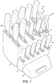
- a culinary knife block assembly 10 includes a main block 12, an auxiliary block 14 and a stand 16, each made of wood although other materials could be used in other embodiments, these three components being secured together for example by adhesive.
- the main block has a series of ten culinary utensil holders in the form of knife holders 18 formed in two rows of five holders each, plus a scissor holder 20.
- the knife holders 18 are identical to one another and hold an array of knives 22 having blades with varying configurations, including a paring knife 22a, as shown in Figure 4 , with a relatively short blade 24 with a relatively short depth near the handle 26 from the sharp lower edge 28 to the top edge 30.
- the knives also include a chef's knife 22b which, as shown in Figure 5 , has a long blade 32, longer than the blade 24, with a large depth near the handle 34 thereof in the direction between its sharp lower edge 36 and its top edge 38, this depth being greater than the equivalent depth in the paring knife 22a shown in Figure 4 .
- a pair of scissors or shears 40 is inserted in the scissor holder 20.
- the auxiliary block 14 includes a series of six auxiliary culinary holders 42 in the form of auxiliary knife holders 42, the auxiliary knife holders 42 in this embodiment each holding one of a matched set of culinary preparation knives 44.
- the culinary knife block assembly 10 also includes four support feet 46 which are circular pads which are fixed to the main block 12 and the stand 16 and/or the auxiliary block 14 for supporting the culinary knife block assembly 10 on a work surface (not shown).
- the knife holders 18, scissor holder 20 and auxiliary knife holders 42 are formed in the shape of sheaths for insertion in corresponding slots 48, 50, 52 which extend all of the way through the main block 12 and auxiliary block 14 from respective top surfaces 54, 56 to bottom surfaces 58, 60 thereof.
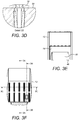
- Each of the slots 48, 50, 52 comprises a rectangular tube, the slots 48, 50, 52 having respective latch recesses 62, 64, 66 formed at the bottom surfaces 58, 60, these recesses 62, 64, 66 being marked at least in Figures 3A, 3B , 6A, 6B and 7A .
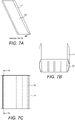
- each of the knife holders 18 comprises a body 68 having an entrance 70 in the form of an elongate ring connected by connectors 72, 74 to side walls 76, 78 having an inner slot 80 formed therebetween.
- the side walls 76, 78 include flexible entrance tongues 82, 84 positioned between the connectors 72, 74, each of the tongues 82, 84 being formed with a series of five elongate friction ribs extending along the longitudinal direction of the inner slot 80 and being mutually spaced apart, the respective ribs 86 being arranged to be closely spaced from one another or to resiliently engage one another when the flexible entrance tongues 82, 84 are in a rest configuration thereof with no knife positioned in the inner slot 80.
- Each of the flexible entrance tongues 82, 84 also includes a flared entrance guide member 88, 90 arranged for guiding one of the knives 22a, 22b, 22 into the inner slot 80.
- the knife holder 18 also includes at a lower end 92 thereof a resilient latch 94 for engagement in a respective latch recess 62 of the main block 12 to hold the knife holder 18 firmly within the main block 12 until the resilient latch 94 is operated to release the knife holder 18 from the main block 12 for cleaning purposes.
- the knife holder 18 is integrally formed by moulding.
- a user may insert any of the knives 22 including the knives 22a, 22b through the entrance ring 70, which is relatively rigid, the knife 22 being guided by the resilient entrance guide members 88, 90 through to engage the friction ribs/formations 86 and the knife may thus be fully inserted into the knife holder 18, with the engagement of the friction ribs 86 with the blade 24, 32 holding the knife in the configuration in which it is left by the user, such that knives of various sizes may be inserted into the knife holder 18 and held in the desired configuration as left by the user.
- the knife may later be withdrawn against the friction of the friction ribs/formations 86 and with the resilient latch 94 holding the knife holder 18 in the main block 12.
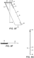
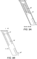
- each auxiliary knife holder 42 essentially comprises a smaller version of each of the knife holders 18 so will not be described in detail, although it is noted from Figure 9A that only three friction ribs 86' are provided on each side wall 76', 78' of the auxiliary knife holder 42 and resilient latches 94' are engageable within the latch recesses 66.
- the scissor holder 20 is similar to the knife holders 18 and auxiliary knife holders 42 although has no friction ribs/formations in this particular embodiment even though they could be included in other embodiments.
- the scissor holder 20 does, however, include a resilient latch 94" for engagement in the latch recess 66 of the main block 12.
- the scissor holder 20 may alternatively be used for storing other implements, such as shears, e.g. poultry shears, and knife sharpening steels or other implements.
- the auxiliary block 14 and/or stand 16 may be omitted and the main block 12 may be reshaped to manage the position of the centre of gravity with it loaded or unloaded, accordingly.
- the user may easily place their various knives and other implements in the particular knife holders 18 that they desire and are not constrained as in the prior art by only having defined positions for the knives/implements.
- the knife holders 18 and auxiliary knife holders 42 may accommodate knives of varying knife shapes and sizes and the handles thereof may be lined up relative to the main block 12 and auxiliary block 14 as desired by the user, advantageously by engagement of the blades therefore with the friction ribs/formations 86, i.e. without having a knife with a small blade having its handle droop by gravity to a low misaligned position.
- the knife holders 18 and auxiliary knife holders 42 may, using the resilient latches 94, 94', 94", be conveniently removed from the main block 12 and auxiliary block 14 for cleaning purposes or replacement.
- one or more knife holders 18 and/or one or more of the auxiliary knife holders 42 may be formed integrally within a culinary block, and/or one or more knife holders or auxiliary knife holders may be formed integrally with one another.
Landscapes
- Engineering & Computer Science (AREA)
- Life Sciences & Earth Sciences (AREA)
- Forests & Forestry (AREA)
- Mechanical Engineering (AREA)
- Food Science & Technology (AREA)
- Table Equipment (AREA)
- Devices For Warming Or Keeping Food Or Tableware Hot (AREA)
- Food-Manufacturing Devices (AREA)
Priority Applications (3)
| Application Number | Priority Date | Filing Date | Title |
|---|---|---|---|
| EP16186913.6A EP3289931A1 (fr) | 2016-09-01 | 2016-09-01 | Supports d'ustensiles culinaires |
| CN201710684728.4A CN107788886A (zh) | 2016-09-01 | 2017-08-11 | 厨具架 |
| US15/693,384 US20180055259A1 (en) | 2016-09-01 | 2017-08-31 | Culinary Utensil Holders |
Applications Claiming Priority (1)
| Application Number | Priority Date | Filing Date | Title |
|---|---|---|---|
| EP16186913.6A EP3289931A1 (fr) | 2016-09-01 | 2016-09-01 | Supports d'ustensiles culinaires |
Publications (1)
| Publication Number | Publication Date |
|---|---|
| EP3289931A1 true EP3289931A1 (fr) | 2018-03-07 |
Family
ID=56855329
Family Applications (1)
| Application Number | Title | Priority Date | Filing Date |
|---|---|---|---|
| EP16186913.6A Withdrawn EP3289931A1 (fr) | 2016-09-01 | 2016-09-01 | Supports d'ustensiles culinaires |
Country Status (3)
| Country | Link |
|---|---|
| US (1) | US20180055259A1 (fr) |
| EP (1) | EP3289931A1 (fr) |
| CN (1) | CN107788886A (fr) |
Families Citing this family (7)
| Publication number | Priority date | Publication date | Assignee | Title |
|---|---|---|---|---|
| USD986690S1 (en) * | 2021-09-28 | 2023-05-23 | Yiting Chen | Knife holder with sharpener |
| USD1054799S1 (en) * | 2022-02-10 | 2024-12-24 | Sharkninja Operating Llc | Knife sharpener block |
| US20230380636A1 (en) * | 2022-05-24 | 2023-11-30 | Takos LLC | Kitchen Implement Organizer |
| US12042070B2 (en) * | 2022-08-19 | 2024-07-23 | Instant Brands Holdings Inc. | Knife block and knife storage system |
| USD1111702S1 (en) * | 2022-08-19 | 2026-02-10 | Corelle Brands Holdings Inc. | Knife block |
| US12310519B1 (en) * | 2023-08-10 | 2025-05-27 | Caraway Home, Inc. | Modular culinary implement storage system |
| US12543875B2 (en) * | 2024-02-21 | 2026-02-10 | Mirza Faizan | Knife holder for a knife |
Citations (8)
| Publication number | Priority date | Publication date | Assignee | Title |
|---|---|---|---|---|
| US3381807A (en) * | 1966-11-21 | 1968-05-07 | Donald H. De Vaughn | Sheath for knives |
| JPS5864248U (ja) * | 1981-10-24 | 1983-04-30 | 田辺金属株式会社 | 包丁ケ−ス |
| JPH0384051U (fr) * | 1989-12-15 | 1991-08-27 | ||
| JPH0720149U (ja) * | 1993-09-07 | 1995-04-11 | パール金属株式会社 | 俎板スタンド |
| WO2001015872A2 (fr) * | 1999-08-31 | 2001-03-08 | The Pampered Chef, Ltd. | Protection pour la lame d'un couteau |
| GB2363316A (en) * | 2000-06-15 | 2001-12-19 | Master Cutlery Corp | Holder for knives |
| US20050258115A1 (en) * | 2004-05-21 | 2005-11-24 | Smith Dustin G | Space saving swivel block utensil holder |
| US20070278165A1 (en) | 2006-03-10 | 2007-12-06 | Ranieri Laura A | Knife block with protective knife slot inserts |
-
2016
- 2016-09-01 EP EP16186913.6A patent/EP3289931A1/fr not_active Withdrawn
-
2017
- 2017-08-11 CN CN201710684728.4A patent/CN107788886A/zh active Pending
- 2017-08-31 US US15/693,384 patent/US20180055259A1/en not_active Abandoned
Patent Citations (8)
| Publication number | Priority date | Publication date | Assignee | Title |
|---|---|---|---|---|
| US3381807A (en) * | 1966-11-21 | 1968-05-07 | Donald H. De Vaughn | Sheath for knives |
| JPS5864248U (ja) * | 1981-10-24 | 1983-04-30 | 田辺金属株式会社 | 包丁ケ−ス |
| JPH0384051U (fr) * | 1989-12-15 | 1991-08-27 | ||
| JPH0720149U (ja) * | 1993-09-07 | 1995-04-11 | パール金属株式会社 | 俎板スタンド |
| WO2001015872A2 (fr) * | 1999-08-31 | 2001-03-08 | The Pampered Chef, Ltd. | Protection pour la lame d'un couteau |
| GB2363316A (en) * | 2000-06-15 | 2001-12-19 | Master Cutlery Corp | Holder for knives |
| US20050258115A1 (en) * | 2004-05-21 | 2005-11-24 | Smith Dustin G | Space saving swivel block utensil holder |
| US20070278165A1 (en) | 2006-03-10 | 2007-12-06 | Ranieri Laura A | Knife block with protective knife slot inserts |
Also Published As
| Publication number | Publication date |
|---|---|
| US20180055259A1 (en) | 2018-03-01 |
| CN107788886A (zh) | 2018-03-13 |
Similar Documents
| Publication | Publication Date | Title |
|---|---|---|
| US20180055259A1 (en) | Culinary Utensil Holders | |
| US6877231B2 (en) | Expandable knife holder | |
| JP4843666B2 (ja) | 汎用おろし器 | |
| EP3415000A1 (fr) | Outil et procédés de toilettage | |
| US7267238B2 (en) | Retainer block for use with dish rack | |
| US20160367055A1 (en) | Interconnectable utensil holders | |
| US20110094111A1 (en) | Food processing tool | |
| EP2682070B1 (fr) | Plateau de transport d'instruments chirurgicaux | |
| US20090100679A1 (en) | Shaving apparatus and methods | |
| US5113587A (en) | Cutting instrument | |
| US20170100848A1 (en) | Cutting board with removable pivot knife | |
| US20070278165A1 (en) | Knife block with protective knife slot inserts | |
| CN111528672A (zh) | 刀架 | |
| US20170071587A1 (en) | Weighted surgical retractor systems | |
| US9480366B2 (en) | Lid holding device | |
| SE446439B (sv) | Knivslida med inbyggd bladskerpare | |
| CN114667204B (zh) | 磨刃装置 | |
| US20160288352A1 (en) | Knife having removable blade guard | |
| JPH021637B2 (fr) | ||
| US7536793B1 (en) | Safety stand and knife and method of use | |
| HUP0302401A2 (hu) | Tartóberendezés kés számára | |
| JP6145557B1 (ja) | 刃部材を交換可能な調理器具 | |
| US20190281803A1 (en) | Minnow Holding Assembly | |
| JP2016507308A (ja) | 手術用メスからブレードを取り外すのに用いる方法及び装置 | |
| EP2366510A1 (fr) | Gabarit support pour grands biospécimens frais |
Legal Events
| Date | Code | Title | Description |
|---|---|---|---|
| PUAI | Public reference made under article 153(3) epc to a published international application that has entered the european phase |
Free format text: ORIGINAL CODE: 0009012 |
|
| AK | Designated contracting states |
Kind code of ref document: A1 Designated state(s): AL AT BE BG CH CY CZ DE DK EE ES FI FR GB GR HR HU IE IS IT LI LT LU LV MC MK MT NL NO PL PT RO RS SE SI SK SM TR |
|
| AX | Request for extension of the european patent |
Extension state: BA ME |
|
| STAA | Information on the status of an ep patent application or granted ep patent |
Free format text: STATUS: THE APPLICATION IS DEEMED TO BE WITHDRAWN |
|
| 18D | Application deemed to be withdrawn |
Effective date: 20180908 |