EP3289972B1 - Procédé et système d'utilisation intra-opératoire de fluorescence et ses applications - Google Patents
Procédé et système d'utilisation intra-opératoire de fluorescence et ses applications Download PDFInfo
- Publication number
- EP3289972B1 EP3289972B1 EP17196217.8A EP17196217A EP3289972B1 EP 3289972 B1 EP3289972 B1 EP 3289972B1 EP 17196217 A EP17196217 A EP 17196217A EP 3289972 B1 EP3289972 B1 EP 3289972B1
- Authority
- EP
- European Patent Office
- Prior art keywords
- fluorescence
- tissue
- parathyroid
- thyroid
- light
- Prior art date
- Legal status (The legal status is an assumption and is not a legal conclusion. Google has not performed a legal analysis and makes no representation as to the accuracy of the status listed.)
- Revoked
Links
Images





Classifications
-
- A—HUMAN NECESSITIES
- A61—MEDICAL OR VETERINARY SCIENCE; HYGIENE
- A61B—DIAGNOSIS; SURGERY; IDENTIFICATION
- A61B5/00—Measuring for diagnostic purposes; Identification of persons
- A61B5/41—Detecting, measuring or recording for evaluating the immune or lymphatic systems
- A61B5/414—Evaluating particular organs or parts of the immune or lymphatic systems
- A61B5/415—Evaluating particular organs or parts of the immune or lymphatic systems the glands, e.g. tonsils, adenoids or thymus
-
- A—HUMAN NECESSITIES
- A61—MEDICAL OR VETERINARY SCIENCE; HYGIENE
- A61B—DIAGNOSIS; SURGERY; IDENTIFICATION
- A61B34/00—Computer-aided surgery; Manipulators or robots specially adapted for use in surgery
- A61B34/20—Surgical navigation systems; Devices for tracking or guiding surgical instruments, e.g. for frameless stereotaxis
-
- A—HUMAN NECESSITIES
- A61—MEDICAL OR VETERINARY SCIENCE; HYGIENE
- A61B—DIAGNOSIS; SURGERY; IDENTIFICATION
- A61B5/00—Measuring for diagnostic purposes; Identification of persons
- A61B5/0059—Measuring for diagnostic purposes; Identification of persons using light, e.g. diagnosis by transillumination, diascopy, fluorescence
- A61B5/0071—Measuring for diagnostic purposes; Identification of persons using light, e.g. diagnosis by transillumination, diascopy, fluorescence by measuring fluorescence emission
-
- A—HUMAN NECESSITIES
- A61—MEDICAL OR VETERINARY SCIENCE; HYGIENE
- A61B—DIAGNOSIS; SURGERY; IDENTIFICATION
- A61B5/00—Measuring for diagnostic purposes; Identification of persons
- A61B5/0059—Measuring for diagnostic purposes; Identification of persons using light, e.g. diagnosis by transillumination, diascopy, fluorescence
- A61B5/0075—Measuring for diagnostic purposes; Identification of persons using light, e.g. diagnosis by transillumination, diascopy, fluorescence by spectroscopy, i.e. measuring spectra, e.g. Raman spectroscopy, infrared absorption spectroscopy
-
- A—HUMAN NECESSITIES
- A61—MEDICAL OR VETERINARY SCIENCE; HYGIENE
- A61B—DIAGNOSIS; SURGERY; IDENTIFICATION
- A61B5/00—Measuring for diagnostic purposes; Identification of persons
- A61B5/0059—Measuring for diagnostic purposes; Identification of persons using light, e.g. diagnosis by transillumination, diascopy, fluorescence
- A61B5/0082—Measuring for diagnostic purposes; Identification of persons using light, e.g. diagnosis by transillumination, diascopy, fluorescence adapted for particular medical purposes
- A61B5/0084—Measuring for diagnostic purposes; Identification of persons using light, e.g. diagnosis by transillumination, diascopy, fluorescence adapted for particular medical purposes for introduction into the body, e.g. by catheters
- A61B5/0086—Measuring for diagnostic purposes; Identification of persons using light, e.g. diagnosis by transillumination, diascopy, fluorescence adapted for particular medical purposes for introduction into the body, e.g. by catheters using infrared radiation
-
- A—HUMAN NECESSITIES
- A61—MEDICAL OR VETERINARY SCIENCE; HYGIENE
- A61B—DIAGNOSIS; SURGERY; IDENTIFICATION
- A61B5/00—Measuring for diagnostic purposes; Identification of persons
- A61B5/41—Detecting, measuring or recording for evaluating the immune or lymphatic systems
- A61B5/414—Evaluating particular organs or parts of the immune or lymphatic systems
- A61B5/418—Evaluating particular organs or parts of the immune or lymphatic systems lymph vessels, ducts or nodes
-
- A—HUMAN NECESSITIES
- A61—MEDICAL OR VETERINARY SCIENCE; HYGIENE
- A61B—DIAGNOSIS; SURGERY; IDENTIFICATION
- A61B5/00—Measuring for diagnostic purposes; Identification of persons
- A61B5/42—Detecting, measuring or recording for evaluating the gastrointestinal, the endocrine or the exocrine systems
- A61B5/4222—Evaluating particular parts, e.g. particular organs
- A61B5/4227—Evaluating particular parts, e.g. particular organs endocrine glands, i.e. thyroid, adrenals, hypothalamic, pituitary
-
- A—HUMAN NECESSITIES
- A61—MEDICAL OR VETERINARY SCIENCE; HYGIENE
- A61B—DIAGNOSIS; SURGERY; IDENTIFICATION
- A61B5/00—Measuring for diagnostic purposes; Identification of persons
- A61B5/74—Details of notification to user or communication with user or patient; User input means
- A61B5/742—Details of notification to user or communication with user or patient; User input means using visual displays
-
- G—PHYSICS
- G01—MEASURING; TESTING
- G01N—INVESTIGATING OR ANALYSING MATERIALS BY DETERMINING THEIR CHEMICAL OR PHYSICAL PROPERTIES
- G01N21/00—Investigating or analysing materials by the use of optical means, i.e. using sub-millimetre waves, infrared, visible or ultraviolet light
- G01N21/62—Systems in which the material investigated is excited whereby it emits light or causes a change in wavelength of the incident light
- G01N21/63—Systems in which the material investigated is excited whereby it emits light or causes a change in wavelength of the incident light optically excited
- G01N21/64—Fluorescence; Phosphorescence
- G01N21/645—Specially adapted constructive features of fluorimeters
- G01N21/6456—Spatial resolved fluorescence measurements; Imaging
-
- G—PHYSICS
- G01—MEASURING; TESTING
- G01N—INVESTIGATING OR ANALYSING MATERIALS BY DETERMINING THEIR CHEMICAL OR PHYSICAL PROPERTIES
- G01N21/00—Investigating or analysing materials by the use of optical means, i.e. using sub-millimetre waves, infrared, visible or ultraviolet light
- G01N21/62—Systems in which the material investigated is excited whereby it emits light or causes a change in wavelength of the incident light
- G01N21/63—Systems in which the material investigated is excited whereby it emits light or causes a change in wavelength of the incident light optically excited
- G01N21/65—Raman scattering
-
- A—HUMAN NECESSITIES
- A61—MEDICAL OR VETERINARY SCIENCE; HYGIENE
- A61B—DIAGNOSIS; SURGERY; IDENTIFICATION
- A61B34/00—Computer-aided surgery; Manipulators or robots specially adapted for use in surgery
- A61B34/20—Surgical navigation systems; Devices for tracking or guiding surgical instruments, e.g. for frameless stereotaxis
- A61B2034/2046—Tracking techniques
- A61B2034/2055—Optical tracking systems
-
- A—HUMAN NECESSITIES
- A61—MEDICAL OR VETERINARY SCIENCE; HYGIENE
- A61B—DIAGNOSIS; SURGERY; IDENTIFICATION
- A61B2505/00—Evaluating, monitoring or diagnosing in the context of a particular type of medical care
- A61B2505/05—Surgical care
-
- G—PHYSICS
- G01—MEASURING; TESTING
- G01N—INVESTIGATING OR ANALYSING MATERIALS BY DETERMINING THEIR CHEMICAL OR PHYSICAL PROPERTIES
- G01N21/00—Investigating or analysing materials by the use of optical means, i.e. using sub-millimetre waves, infrared, visible or ultraviolet light
- G01N21/62—Systems in which the material investigated is excited whereby it emits light or causes a change in wavelength of the incident light
- G01N21/63—Systems in which the material investigated is excited whereby it emits light or causes a change in wavelength of the incident light optically excited
- G01N21/64—Fluorescence; Phosphorescence
- G01N21/6428—Measuring fluorescence of fluorescent products of reactions or of fluorochrome labelled reactive substances, e.g. measuring quenching effects, using measuring "optrodes"
- G01N2021/6439—Measuring fluorescence of fluorescent products of reactions or of fluorochrome labelled reactive substances, e.g. measuring quenching effects, using measuring "optrodes" with indicators, stains, dyes, tags, labels, marks
-
- G—PHYSICS
- G01—MEASURING; TESTING
- G01N—INVESTIGATING OR ANALYSING MATERIALS BY DETERMINING THEIR CHEMICAL OR PHYSICAL PROPERTIES
- G01N2201/00—Features of devices classified in G01N21/00
- G01N2201/02—Mechanical
- G01N2201/022—Casings
- G01N2201/0221—Portable; cableless; compact; hand-held
Definitions
- n represents the nth reference cited in the reference list.
- []6 represents the 6th reference cited in the reference list, namely, Frilling, A. & Weber, F. Complications in Thyroid and Parathyroid Surgery. in Surgery. of the Thyroid and Parathyroid Glands 217-224 (2007 ).
- the endocrine system is a complex system of organs and glands which includes the thyroid and parathyroid.
- the anatomy of the neck is illustrated in Figure 1 .
- the thyroid gland regulates many developmental and metabolic processes. Common diseases of the thyroid include goiters, hyperthyroidism, hypothyroidism, benign and malignant nodules, and autoimmune diseases such as Graves' disease. Surgery is the most common treatment for Graves's disease, goiters, benign thyroid nodules, and thyroid cancers.
- the parathyroid lies within the same region as the thyroid in the neck and functions to control calcium levels in the blood.
- the most common parathyroid disorder is primary hyperparathyroidism, in which one or more of the parathyroid glands become enlarged and hyperactive. This causes excess secretion of parathyroid hormone and a disruption in normal bone and mineral metabolism.
- the prevalence of primary hyperparathyroidism has been estimated at 21 cases per 100,000 person-years. In 80% of cases, primary hyperparathyroidism is caused by a single overactive parathyroid gland and surgical removal of the diseased parathyroid gland is the only definitive treatment.
- tan parathyroid glands typically there are four tan parathyroid glands, each approximately 6 to 8 mm in size. They are typically positioned within the neck but can vary in location within the body and are sometimes intrathymic. Due to their small size and variability in position, the parathyroid glands are often difficult to distinguish from surrounding tissue and thyroid in the neck. The parathyroid visually resembles its surrounding tissue and this can extend surgical time during a parathyroidectomy, during which the surgeon is simply searching for the small organ. Accidental removal or damage to healthy parathyroids during parathyroid or thyroid surgery can result in serious complications such as hypocalcemia or hypoparathyroidism. Hypoparathyroidism may result from direct injury, devascularization, and/or disruption of the parathyroid glands. Statistics suggest that temporary and permanent hypoparathyroidism rates are between 4-20% during thyroid surgery. The most common complications of both parathyroid and thyroid surgery are postoperative hypocalcemia, vocal-cord paralysis, and hematoma.
- the current surgical procedure for thyroid and parathyroid surgeries involves a systematic search within the neck in which the surgeon is mainly relying on visual inspection to identify target tissues.
- the incidence of complications occurring due to this subjective method is directly proportional to the extent of thyroidectomy and inversely proportional to the experience of the surgeon.
- the disadvantages to the current method include the lengthy duration of the surgery, the exploratory nature of the surgery, and the lack of preoperative and intra-operative imaging. Confirmation of removal of the diseased parathyroid relies on histopathology or post-operative diagnosis of symptoms. There is a need for a reliable imaging system to help identify the parathyroid glands intra-operatively.
- US 2004/0109231 A1 is focused on the approach to administer a fluorescent substance, like ICG (indocyanine green) to the patient by intravenous injection, to observe fluorescence spectra resulting from this fluorescent substance and therewith no autofluorescence.
- a fluorescent substance like ICG (indocyanine green)
- the excitation is done at 800 nm or in the range 820 to 870 nm and the fluorescence is observed between 820 and 920 nm or in the range 820 to 870 nm.
- An intraoperative observation and documentation of blood flow in small arterial vessels is mentioned as well. It is further explained that other fluorescence substances besides indocyanine green may be used, including substances of the human body that provide for auto-fluorescence.
- US 2004/0006275 A1 describes to obtaining auto-fluorescence a helium-neon laser operating at about 633 nm or an unspecified monochromatic laser source operating at wavelengths from about 250 nm to about 1100 nm is used or alternatively a solid-state laser operating at 523 nm is used.
- a helium-neon laser operating at about 633 nm or an unspecified monochromatic laser source operating at wavelengths from about 250 nm to about 1100 nm is used or alternatively a solid-state laser operating at 523 nm is used.
- One object is image and differentiate malignant tumors from benign tumors and normal tissues.
- the present invention provides process for intra-operatively providing anatomical guidance in an endocrine surgery as is defined in claim 1.
- a preferred embodiment is defined in claim 2.
- the invention enables to distinguish between the parathyroid and the thyroid and of course also other tissue in the neck area, based on auto-fluorescence. This can be helpful for a medical professional performing endocrine surgery in the neck area and can make such surgery safer and less time consuming, with corresponding benefits for patients needing such surgery.
- Radar spectroscopy refers to an optical technique that probes the specific molecular content of a sample by collecting in-elastically scattered light. As photons propagate through a medium, they undergo both absorptive and scattering events. In absorption, the energy of the photons is completely transferred to the material, allowing either heat transfer (internal conversion) or re-emission phenomena such as fluorescence and phosphorescence to occur. Scattering, however, is normally an in-elastic process, in which the incident photons retain their energy. In Raman scattering, the photons either donate or acquire energy from the medium, on a molecular level.
- the energy transfers associated with Raman scattering are on the order of the vibrational modes of the molecule. These vibrational modes are molecularly specific, giving every molecule a unique Raman spectral signature.
- Raman scattering is a very weak phenomena, and therefore practical measurement of Raman spectra of a medium requires high power excitation laser sources and extremely sensitive detection hardware. Even with these components, the Raman spectra from tissue are masked by the relatively intense tissue auto-fluorescence. After detection, post processing techniques are required to subtract the fluorescent background and enable accurate visualization of the Raman spectra.
- Raman spectra are plotted as a function of frequency shift in units of wavenumber (cm-1). The region of the Raman spectra where most biological molecules have Raman peaks is from 500 to 2000 cm-1 . In contrast to fluorescence spectra, Raman spectra have sharp spectral features that enable easier identification of the constituent sources of spectral peaks in a complex sample. In the context of detecting the changes that cancerous tissues undergo, differences in the Raman spectral features that correlate to the increased nucleic acid content in neoplastic cells has observed.
- fluorescence spectroscopy or its acronym “fluorometry” or “spectrofluorometry” refers to a type of electromagnetic spectroscopy which analyzes fluorescence from a sample. It involves using a beam of light, usually ultraviolet light, that excites the electrons in molecules of certain compounds and causes them to emit light of a lower energy, typically, but not necessarily, visible light.
- a complementary technique is absorption spectroscopy.
- Fluorescence spectroscopy utilizes that fact that molecules have various states referred to as energy levels. Fluorescence spectroscopy is primarily concerned with electronic and vibrational states of energy. Generally, the sample being examined will have a ground electronic state (a low energy state) of interest, and an excited electronic state of higher energy. Within each of these electronic states are various vibrational states.
- the sample In fluorescence spectroscopy, the sample is first excited, by absorbing a photon, from its ground electronic state to one of the various vibrational states in the excited electronic state. Collisions with other molecules cause the excited molecule to lose vibrational energy until it reaches the lowest vibrational state of the excited electronic state.
- the molecule then drops down to one of the various vibrational levels of the ground electronic state again, emitting a photon in the process.
- the emitted photons will have different energies, and thus frequencies. Therefore, by analysing the different frequencies of light emitted in fluorescent spectroscopy, along with their relative intensities, the structure of the different vibrational levels can be determined.
- an excitation spectrum is measured by recording a number of emission spectra using different wavelengths of excitation light.
- auto-fluorescence refers to the fluorescence of other substances than the fluorophore of interest. It increases the background signal. Auto-fluorescence can be problematic in fluorescence microscopy. In most fluorescence microscopy, fluorescent stains (such as fluorescently-labeled antibodies) are applied to samples to stain specific structures. Auto-fluorescence interferes with detection of the resulting specific fluorescent signals, especially when the signals of interest are very dim - it causes structures other than those of interest to become visible. Depending upon the shape of the structures of interest and the other structures, it may not be obvious that this has occurred. In some microscopes (mainly confocal microscopes), it is possible to make use of different lifetime of the excited states of the added fluorescent markers and the endogenous molecules to exclude most of the autofluorescence.
- fluorescent stains such as fluorescently-labeled antibodies
- auto-fluorescence may actually illuminate the structures of interest, or serve as a useful diagnostic indicator such as in the case of "biological auto-fluorescence", which refers to the fact that cells contain molecules, which become fluorescent when excited by UV/Vis radiation of suitable wavelength.
- biological auto-fluorescence refers to the fact that cells contain molecules, which become fluorescent when excited by UV/Vis radiation of suitable wavelength.
- This fluorescence emission arising from endogenous fluorophores, is an intrinsic property of cells and is called auto-fluorescence to be distinguished from fluorescent signals obtained by adding exogenous markers.
- the majority of cell auto-fluorescence originates from mitochondria and lysosomes. Together with aromatic amino acids and lipo-pigments, the most important endogenous fluorophores are pyridinic (NADPH) and flavin coenzymes.
- the extracellular matrix In tissues, the extracellular matrix often contributes to the auto-fluorescence emission more than the cellular component, because collagen and elastin have, among the endogenous fluorophores, a relatively high quantum yield. Changes occurring in the cell and tissue state during physiological and/or pathological processes result in modifications of the amount and distribution of endogenous fluorophores and chemical-physical properties of their microenvironment. Therefore, analytical techniques based on auto-fluorescence monitoring may be utilized in order to obtain information about morphological and physiological state of cells and tissues. Moreover, auto-fluorescence analysis can be performed in real time because it does not require any treatment of fixing or staining of the specimens. In the past few years spectroscopic and imaging techniques have been developed for many different applications both in basic research and diagnostics. [ See Biotechnol Annu Rev. 2005; 11:227-56 . Cell and tissue autofluorescence research and diagnostic applications. Monici M.] The present invention provides a case where autofluorescence finds good use.
- charge-coupled device refers to an analog shift register that enables the transportation of analog signals (electric charges) through successive stages (capacitors), controlled by a clock signal.
- Charge-coupled devices can be used as a form of memory or for delaying samples of analog signals.
- a CCD for capturing images there is a photoactive region (an epitaxial layer of silicon), and a transmission region made out of a shift register (the CCD, properly speaking).
- An image is projected through a lens onto the capacitor array (the photoactive region), causing each capacitor to accumulate an electric charge proportional to the light intensity at that location.
- a one-dimensional array used in line-scan cameras, captures a single slice of the image, while a two-dimensional array, used in video and still cameras, captures a two-dimensional picture corresponding to the scene projected onto the focal plane of the sensor.
- a control circuit causes each capacitor to transfer its contents to its neighbor (operating as a shift register).
- the last capacitor in the array dumps its charge into a charge amplifier, which converts the charge into a voltage.
- the controlling circuit converts the entire semiconductor contents of the array to a sequence of voltages, which it samples, digitizes and stores in some form of memory.
- thyroid and parathyroid diseases combine the fields of endocrinology and oncology leading to a complex combination of conditions 1 .
- surgical means are used to remove the diseased gland(s).
- the thyroid gland, parathyroid glands, nerves, adipose tissue, and lymph nodes are closely positioned in the neck region. Due to their close proximity and tendency to blend into each other, many of these structures, specifically the parathyroid glands, are difficult to distinguish visually during endocrine surgery. The situation is further complicated by its small size and variability in position. Surgeons must ultimately rely on visual inspection to identify the different tissues, which can be subjective and often inconclusive 2,3 . Complications occur when the parathyroid is accidentally injured or removed during thyroidectomies or only partially removed in the case of parathyroidectomies 4 .
- the present invention provides a process or method of using near-infrared autofluorescence for the identification of the parathyroid in vivo during endocrine surgery. It is referred to claim 1. Such a method aims to prevent accidental or incomplete removal of parathyroid glands.
- Real time imaging systems that can detect the near infrared auto-fluorescence from the tissues in the neck in real time to guide surgical resection or surgical procedure can favorably be used.
- a spectral imaging system which provides x-y spatial imaging with spectral information in the z direction, was built to detect near-infrared autofluorescence.
- the system includes a near infrared light source for emitting a beam of near-infrared light, a light guide or optical fiber(s) that delivers the light to the tissue, a camera mounted on a stand or to an optical microscope, with a variable filter that can select emission wavelengths, and a computer with a controller in communication with each component/device of the system to coordinate the operation.
- tissue was placed under the camera, the near infrared auto-fluorescence imaging signals from the tissue were collected and acquired through the camera, and stored in a memory for further processing.
- an imaging system provides an x-y image (or video image) of the field at a given NIR wavelength with the sensitivity needed for tissue fluorescence measurements.
- An exemplary device was built with a FIND-R-SCOPE ® .
- Such a system can be made as a portable and hand-held device, in which the image is viewed through a built-in viewer by a user such as a surgeon to see the auto-fluorescence from the tissue or from the targeted area of the tissues on site.
- the viewer can also be connected to a display with or without a CCD camera attachment.
- the imaging system can be used to guide the surgeon intra-operatively through a surgical procedure to identify the tissues that are need to be acted on.
- NIR fluorescence can be used to identify parathyroid glands during thyroid and parathyroidectomies. This utilizes the discovery that parathyroid tissue had unique optical signals to identify the parathyroid glands and differentiate them from other tissues in the neck intra-operatively, in which the intensity of the parathyroid signal was compared to the fluorescence of the surrounding tissue including the thyroid gland.
- fluorescence measurements were conducted on patients who were undergone endocrine surgery at the Vanderbilt University Medical Center. In each of the measurements, the parathyroid had markedly higher levels of fluorescence.
- This example in part illustrates a method or process, with corresponding apparatus or system, according to one example particularly relevant in the context of the present invention.
- a system allows a surgeon to correctly differentiate between thyroid and parathyroid tissue intra-operatively and immediately. Due to their differing optical properties, thyroid, parathyroid and fat can be easily differentiated intra-operatively by the system.
- the system described in this Example allows the 822 nm light created by the thyroid and parathyroid to be viewed directly by the surgeon as visible light.
- the parathyroid visualization unit is easy to use, requiring as little training as possible. It also effectively decreases operative time and the number of unsuccessful operations, thereby greatly reducing the need for costly secondary operations.
- the system may be coupled with equipment already present in the operating room ("OR").
- the system uses optical fibers running from a light source such as a 785 nm laser source to excite the tissue, and return fibers running to a detector to detect and quantify the intensity of the fluorescence coming off of the tissue.
- the system has a display device, allowing for the surgeon to view the differing fluorescence of the two or more tissue types, instead of interpreting a numerical intensity value.
- the system is attachable to a head-unit that the surgeon could wear during surgery.
- the system is in real-time. This real-time factor could decrease time in the OR by creating an intra-operative imaging modality. This would eliminate the need to send tissue samples to histology during surgery and thus reduce any wait times associated with this.
- the system is adapted to be able to excite an area equal to the size of the surgeon's incision. It was determined that expanding the excitation beam to 1 cm 2 would create a beam with adequate power to excite the parathyroid tissue yet was still great enough in size to also excite the surrounding tissue.
- the different means of exciting a larger area of tissue than a laser independently would excite tried and/or evaluated.
- the diameter of the laser beam was measured at approximately 0.3 cm which is rather smaller than the desired one square centimeter.
- a liquid light guide was utilized because it would excite the desired area of tissue while at the same time, maintain the power necessary to excite the tissue.
- a liquid light guide from Newport ® (Model: 77639 Liquid Light Guide, 420-2000 nm, 0.3 in Core, 3.9 in Bend Radius, 79 in Length) was used in practice.
- This liquid light guide is compatible with light in the NIR, has a great enough numerical aperture such that a fiber from the laser could be directly coupled into the liquid light guide, and is long enough to allow the laser source to be separate from the excitation-detection system.
- Other liquid light guides having comparable parameters can also be utilized in practice.
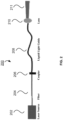
- the excitation setup of the system according to one example embodiment, as shown in Figure 2 used a 785 nm laser coupled to an optical fiber with a diameter of 400 ⁇ m and a numerical aperture of 0.22. This cable was then directly coupled to the liquid light guide. The numerical aperture of the liquid light guide is greater than that of the fiber and thus no optics were needed to couple the fiber to the liquid light guide.
- a Newport ® lens with a focal length of 25.4 mm was used at an approximate distance of 6 cm from the liquid light guide to focus the beam. The diameter of the beam when focused was approximately 1.2 cm.
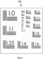
- the NBS 1963A spatial resolution test card shown in Figure 3 was used. The test card was placed on a reflectance pad, a light source was used to provide adequate lighting, and the viewer was then focused to determine the spatial resolution of the viewer. The spatial resolution was defined as the smallest set of line pairs per mm that the viewer could differentiate. Additionally, the spatial resolution of the coupled viewer/camera system was tested. Again, the test card was placed on a reflectance pad, a light source was used to provide adequate lighting, and the viewer/camera system attempted to focus the on decreasingly smaller line pairs.
- the minimum power at which the viewer can detect light at 785 nm was tested.
- the fiber from the laser source was shown onto the reflectance pad and the viewer was looked through while power was lowered.
- the decrease in power was stopped when the spot could no longer be seen through the viewer.
- a power-meter was used to determine the power of the laser at this point. This test yielded the spectral sensitivity of the viewer.
- the minimum power at which the viewer/camera system can detect 785 nm light was also tested using the same method.
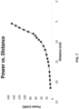
- Power versus Distance Test The next test performed was to determine the relationship between power and distance from the liquid light guide. In a darkened room, the power was measured starting with the light source 21.5 cm from the power meter. The power was measured at approximately one-centimeter intervals with the closest measurement made at a distance of 5.5 cm.
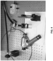
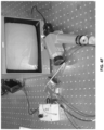
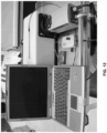
- Tissue Fluorescence Comparison Finally the complete system as photoed in Figure 4 was tested. A moveable arm was built and coupled to the liquid light guide. A cage was built in front of the liquid light guide that created a simple reference to ensure that the light from the liquid light guide was properly focused. This excitation system was used to excite human tissue samples of thyroid and parathyroid. The fluorescence of both the thyroid and the parathyroid were viewed using the viewer and pictures were taken using the camera/viewer-coupled system.
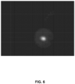
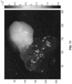
- Spectral Resolution Test Result The minimum power at which near-infrared light could be viewed using the viewer was determined to be 3 nW. The spectral resolution of the viewer/camera-coupled system was found to be 8 nW. Figure 6 is a picture taken with the viewer/camera-coupled system.
- Power versus Distance Test Result The power of the excitation source versus the distance of the laser from the power reader is given in Figure 7 .
- the power needed for tissue excitation is reached at approximately 120 mW at a distance of 6 cm.
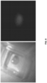
- FIG. 8 shows an image of the tissue captured under normal overhead lighting as well as an image of the fluorescing tissue with all wavelengths below 820 nm being filtered out by the 820 nm long pass filter.
- the average human parathyroid measures 5 x 3 x 1 mm 9 .
- the device is capable of achieving a spatial resolution as good as 0.28 mm. Even with the current camera, the observed resolution of approximately 0.71 mm would still be adequate for locating a parathyroid gland that is smaller than average.
- the device could provide useful complimentary information to currently employed imaging methods for locating parathyroid tissue when operating in the neck region.
- the spatial resolution should be improved in the next generation device however because distinguishing the boundaries of the fluorescing parathyroid can be difficult with the current system.
- the Device Physical Specifications of the Device.
- the system's small size and mobility make it adaptable for different operating room layouts.
- the device could easily be integrated with existing surgical equipment.
- the fact that it can be moved easily from place to place makes it cost-effective, as it reduces the need for the purchase of multiple viewing systems to be used by a single hospital.
- the end of the liquid light guide will need to be held within this distance of 6 cm.
- all non-sterile equipment must be held at least 12 inches away from the sterile field.
- the liquid light guide will require sterilization with each use, and the cord should be covered in sterile material.
- Example 1 a system as illustrated in Example 1 is proved that by using the fluorescent properties of the thyroid and parathyroid the system is able to visually differentiate the different tissue types during thyroid and parathyroid surgeries.
- This system can be developed into a full surgical system that can be installed into operating rooms. Improvements including increased spatial and spectral resolution for both the viewer and any secondary camera system, as well as a fully head mountable detector, viewer and excitation system can be made.
- This system will help to reduce surgical time and the need for secondary surgeries because the system will allow the surgeon to quickly and efficiently differentiate between fat, thyroid and parathyroid.
- This visual cue will help the surgeon quickly differentiate between tissue types and possibly remove the need for sending tissue samples to histology during surgery. This will reduce time in surgery and will ensure that the correct tissue is removed eliminating the need for secondary surgeries.
- Other possible improvements could include image processing to create a real time color map image of the fluorescent profile.
- This example in part illustrates another method or process, with corresponding apparatus or system.
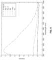
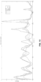
- Fluorescence measurements During the operations, a sterilized optical probe was placed on various tissues in the exposed neck area of a patient and spectral measurements were acquired from each of those sites. The tissue type was noted, as well as the physician's confidence in the investigated sites' histological identity. Spectra were collected using a 300 ms signal collection time. In all cases, the overhead fluorescent lights were turned off during the measurements. Any luminescent lights left on were turned away from the measurement site as they contain spectral components which can interfere with the results. When the tissue was removed in the course of the surgery, specimens from which measurements are taken were then collected for histological identification. All specimens collected were processed and analyzed by a pathologist. Figure 9 depicts a typical spectrum from a patient.
- the signal from the parathyroid gland has the highest peak intensity and is prominently distinguishable from the other tissues in the neck.
- the thyroid gland also shows stronger fluorescence than the surrounding muscle and fat.
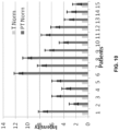
- Figure 10 shows the normalized average peak intensity of parathyroid and thyroid measurements from multiple patients. The two glands are compared within each patient. The results are significant with a p-value of 0.000287069. These results clearly illustrate that parathyroid tissue is at least two times more fluorescent than other tissue found in the neck and was as great as eleven times more fluorescent across all patients. Moreover, data was successfully obtained in vivo. It is believed that this was the first study performed in vivo showing near infrared auto-fluorescence.
- the amount of energy being delivered to the tissue by the laser is low so no damage can occur. Also, it only takes 300 ms to make a measurement and see drastic changes between thyroid and parathyroid fluorescence. The surgeon has a method of identifying parathyroid glands with high accuracy.
- NIR fluorescence is not typically seen in biological tissues 12 . However, in all patients fluorescence is seen above 800 nm, in the range of about 800 nm to 1,000nm, in the thyroid and parathyroid glands but not in the surrounding tissue. This includes fat, muscle, nerve, trachea and lymph tissue. These results raise several questions. Why is this fluorescence only seen in the parathyroid and thyroid glands? Typically fluorescence arises from conjugated bonds providing an excess of pi electrons 12 . Analysis of the tissue and hormone components may be needed to see if the same effect is occurring or if some other phenomenon is responsible. In vitro imaging of the tissues confirmed the fluorescence persists even outside of the body.
- NIR fluorescence provides an accurate detection of parathyroid tissue intra-operatively. Additional patient data can be collected to determine the underlying source of fluorescence. A larger patient database may provide more robust results as well as help develop algorithms to detect and identify parathyroid tissue. A larger population of patients may also help determine and trends in the data that would increase the accuracy of algorithms and help elucidate the basis of fluorescence. Additionally, chemical decomposition and in depth analysis of the absorption and fluorescence may help narrow down the reason that only parathyroid and thyroid have strong fluorescence in the neck. Understanding the basis of NIR fluorescence would help identify where the system might fail as well as uncover a range of biological fluorescence that was not even though to really exist. But there is no doubt that Example 2 shows validity and viability of the present approach.
- This example in part illustrates an apparatus or system, which can be utilized to practice a method or process based on the disclosure herein.
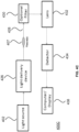
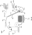
- the system 400A has a light source 402, which is designed to provide a beam of light with appropriate excitation wavelengths and energy so as to excite certain molecules of sample tissue 407, when receiving the beam of light, to generate fluorescence emission.
- the system 400A also has a light delivery and collection device 406, which is optically coupled with the light source 402 and delivers the beam of light from the light source 402 to the tissue 407 and collects optical signals emitted from the tissue 407 responsive to the incident beam of light.
- An optional filter 410 can be utilized to reduce excess wavelengths and/or ambient light to ensure desirable optical signals to be detected.
- the system 400A further has a detector 414, which detects and records the optical signals emitted from the tissue.
- a computer 418 is at least in communication with the detector 414, where the computer 418 is adapted with appropriate controller cards and software to control signal acquisition, process data and display spectra, among other things.
- Fig. 4B shows a photo of a system corresponding to system 400A of Fig. 4A , which was reduced to practice.
- This example in part illustrates an apparatus or system, which can be utilized to practice a method or process based on the disclosure herein.
- the system 400C has a light source 402, which is designed to provide a beam of light with appropriate excitation wavelengths and energy so as to excite certain molecules of sample tissue 407, when receiving the beam of light, to generate fluorescence emission.
- the system 400C also has a light delivery device 426, which is optically coupled with the light source 402 and delivers the beam of light from the light source 402 to the tissue 407.
- An optional filter 430 can be strategically positioned in an optical path 428 along which optical signals emitted from the tissue 407 responsive to the incident beam of light travel and utilized to reduce excess wavelengths and/or ambient light to ensure desirable optical signals to be detected.
- the system 400C further has a detector 434, which detects and records the optical signals emitted from the tissue 407.
- a lens 432 is positioned between the tissue 407 and the detector 434 to receive the optical signals emitted from the tissue and focus them on a desired spot on the detector 434. If an optional filter 430 is utilized, lens 432 will be positioned between the optional filter 430 and the detector 434.
- a computer 438 which has imaging display capacity or is associated with a display device, is at least in communication with the detector 434, where the computer 438 is adapted with appropriate controller cards and software to control signal acquisition, process data and display spectra, among other things.
- the display displays instant images processed by the computer 438 from the optical signals emitted from the tissue 407, which may guide a surgeon or a medical professional through a medical procedure to identify tissues and act on them accordingly.
- Fig. 4D shows a photo of a system corresponding to system 400C of Fig. 4C , which was reduced to practice.
- This example in part illustrates an apparatus or system, which can be utilized to practice a method or process based on the disclosure herein.
- the system 400E has a light source 402, which is designed to provide a beam of light with appropriate excitation wavelengths and energy so as to excite certain molecules of sample tissue 407, when receiving the beam of light, to generate fluorescence emission.
- the system 400E also has a light delivery device 426, which is optically coupled with the light source 402 and delivers the beam of light from the light source 402 to the tissue 407.
- An optional filter 430 can be strategically positioned in an optical path 428 along which optical signals emitted from the tissue 407 responsive to the incident beam of light travel and utilized to reduce excess wavelengths and/or ambient light to ensure desirable optical signals to be detected.
- the system 400C further has a detector 434, which detects and records the optical signals emitted from the tissue 407.
- a lens 432 is positioned between the tissue 407 and the detector 434 to receive the optical signals emitted from the tissue and focus them on a desired spot on the detector 434. If an optional filter 430 is utilized, lens 432 will be positioned between the optional filter 430 and the detector 434.
- a display 438a which has imaging processing and display capacity, is at least in communication with the detector 434, where the display 438a is adapted with appropriate controller cards and software to control signal acquisition, process data and display spectra, among other things.
- the display 438a displays instant images corresponding to the optical signals emitted from the tissue 407, which may guide a surgeon or a medical professional through a medical procedure to identify tissues and act on them accordingly.
- Fig. 4F shows a photo of a system corresponding to system 400E of Fig. 4E , which was reduced to practice.
- This example in part illustrates an apparatus or system, which can be utilized to practice a method or process based on the disclosure herein.
- the system 400G has a light source 452, which is designed to provide a beam of light with appropriate excitation wavelengths and energy so as to excite certain molecules of sample tissue 407, when receiving the beam of light, to generate fluorescence emission.
- the light source 42 is a diode laser capable of generating a beam of laser light with wavelength 785nm and power 80mW. Other suitable light sources can also be utilized in practice.
- a first optical fiber 454 optically couples the light source 452 with a probe 456 that functions as a light delivery and collection device.
- the first optical fiber 454 is a 400 ⁇ m fiber.
- the probe 456 receives a beam of light 403 from the light source 452 through the first optical fiber 454 and delivers it to the tissue 407 through head portion 458.
- the head portion 458 also collects optical signals 405 emitted from the tissue 407 responsive to the incident beam of light 403.
- the head portion 458 is configured with a noise filter 458a and a band pass 458b to maintain the quality of the optical signals.
- a second optical fiber 460 optically couples the probe 456 to means for recording, processing and displaying the optical signals, which, in one example embodiment, includes a spectrograph 466, a CCD 468 and a computer 470 with display, where the CCD 468 is in communication with both spectrograph 466 and computer 470.
- the spectrograph 466 may have internal noise filter installed therein.
- the second optical fiber 460 is optically coupled with the spectrograph 466 through a coupler 464.
- Each of the first optical fiber 454 and the second optical fiber 460 may comprise one or more fibers.
- the second optical fiber 460 has 6 or 7 of 300 ⁇ m fibers arranged in an array.
- CCD 468 and computer 470 adapted with appropriate controller cards and software to control signal acquisition, process data and display spectra, are utilized to process and display images corresponding to the optical signals 405 emitted from the tissue 407, which may guide a surgeon or a medical professional through a medical procedure to identify tissues and act on them accordingly.
- System 400G can be adapted as a portable system.
Landscapes
- Health & Medical Sciences (AREA)
- Life Sciences & Earth Sciences (AREA)
- Physics & Mathematics (AREA)
- General Health & Medical Sciences (AREA)
- Pathology (AREA)
- Surgery (AREA)
- Engineering & Computer Science (AREA)
- Animal Behavior & Ethology (AREA)
- Veterinary Medicine (AREA)
- Biomedical Technology (AREA)
- Heart & Thoracic Surgery (AREA)
- Medical Informatics (AREA)
- Molecular Biology (AREA)
- Public Health (AREA)
- Biophysics (AREA)
- Immunology (AREA)
- Nuclear Medicine, Radiotherapy & Molecular Imaging (AREA)
- Analytical Chemistry (AREA)
- Endocrinology (AREA)
- Chemical & Material Sciences (AREA)
- Vascular Medicine (AREA)
- Biochemistry (AREA)
- General Physics & Mathematics (AREA)
- Spectroscopy & Molecular Physics (AREA)
- Urology & Nephrology (AREA)
- Gastroenterology & Hepatology (AREA)
- Physiology (AREA)
- Robotics (AREA)
- Investigating, Analyzing Materials By Fluorescence Or Luminescence (AREA)
Claims (2)
- Procédé destiné à assurer un guidage anatomique peropératoire lors d'une chirurgie, comprenant(a) l'éclairage de tissus humains (407) dans une région d'un être humain en train d'être opéré avec un faisceau de lumière (403) ;(b) l'obtention de données fluorescentes de la lumière émise par les tissus humains (407) en réponse à l'éclairage présentant une longueur d'onde prédéfinie,
dans lequelle faisceau de lumière (403) présente une longueur d'onde dans le domaine du proche infrarouge et les données fluorescentes comprennent des données auto-fluorescentes de proche infrarouge ;dans lequel le procédé comprend en outre :(c) l'affichage d'images générées à partir des données auto-fluorescentes de proche infrarouge obtenues sur un écran (418 ; 438 ; 438a) pour assurer un guidage anatomique à un professionnel de la médecine réalisant la chirurgie,dans lequel les données auto-fluorescentes de proche infrarouge obtenues comprennent une intensité auto-fluorescente de proche infrarouge, et l'image affichée est générée sur la base de l'intensité auto-fluorescente de proche infrarouge ; caractérisé en ce quela chirurgie est une chirurgie endocrine et la région de l'être humain est la région du cou de l'être humain ;dans lequel la longueur d'onde prédéfinie est choisie de telle sorte que la thyroïde et la parathyroïde émettent, lorsqu'elles sont éclairées par le faisceau de lumière, une auto-fluorescence de 822 nm ; etdans lequel le guidage anatomique est la visualisation des différents types de tissu dans la région du cou pour distinguer la parathyroïde et la thyroïde et d'autres tissus, dans lequel les données auto-fluorescentes de proche infrarouge sont obtenues dans une plage de longueurs d'onde comportant la longueur d'onde de 822 nm. - Procédé selon la revendication 1, caractérisé en ce que le faisceau de lumière présente une longueur d'onde de 785 nm.
Priority Applications (1)
| Application Number | Priority Date | Filing Date | Title |
|---|---|---|---|
| EP23181954.1A EP4235157A3 (fr) | 2008-07-30 | 2009-07-30 | Procédé et système d'utilisation intra-opératoire de fluorescence et ses applications |
Applications Claiming Priority (5)
| Application Number | Priority Date | Filing Date | Title |
|---|---|---|---|
| US13758408P | 2008-07-30 | 2008-07-30 | |
| US13752008P | 2008-07-30 | 2008-07-30 | |
| EP09803612.2A EP2313000B1 (fr) | 2008-07-30 | 2009-07-30 | Spectroscopie de fluorescence peropératoire et ses applications |
| PCT/US2009/052304 WO2010014847A1 (fr) | 2008-07-30 | 2009-07-30 | Spectroscopie de fluorescence peropératoire et ses applications |
| EP15187369.2A EP3005941B1 (fr) | 2008-07-30 | 2009-07-30 | Spectroscopie de fluorescence peropératoire et ses applications |
Related Parent Applications (3)
| Application Number | Title | Priority Date | Filing Date |
|---|---|---|---|
| EP15187369.2A Division-Into EP3005941B1 (fr) | 2008-07-30 | 2009-07-30 | Spectroscopie de fluorescence peropératoire et ses applications |
| EP15187369.2A Division EP3005941B1 (fr) | 2008-07-30 | 2009-07-30 | Spectroscopie de fluorescence peropératoire et ses applications |
| EP09803612.2A Division EP2313000B1 (fr) | 2008-07-30 | 2009-07-30 | Spectroscopie de fluorescence peropératoire et ses applications |
Related Child Applications (2)
| Application Number | Title | Priority Date | Filing Date |
|---|---|---|---|
| EP23181954.1A Division EP4235157A3 (fr) | 2008-07-30 | 2009-07-30 | Procédé et système d'utilisation intra-opératoire de fluorescence et ses applications |
| EP23181954.1A Division-Into EP4235157A3 (fr) | 2008-07-30 | 2009-07-30 | Procédé et système d'utilisation intra-opératoire de fluorescence et ses applications |
Publications (2)
| Publication Number | Publication Date |
|---|---|
| EP3289972A1 EP3289972A1 (fr) | 2018-03-07 |
| EP3289972B1 true EP3289972B1 (fr) | 2023-09-06 |
Family
ID=41610735
Family Applications (4)
| Application Number | Title | Priority Date | Filing Date |
|---|---|---|---|
| EP09803612.2A Active EP2313000B1 (fr) | 2008-07-30 | 2009-07-30 | Spectroscopie de fluorescence peropératoire et ses applications |
| EP15187369.2A Active EP3005941B1 (fr) | 2008-07-30 | 2009-07-30 | Spectroscopie de fluorescence peropératoire et ses applications |
| EP17196217.8A Revoked EP3289972B1 (fr) | 2008-07-30 | 2009-07-30 | Procédé et système d'utilisation intra-opératoire de fluorescence et ses applications |
| EP23181954.1A Withdrawn EP4235157A3 (fr) | 2008-07-30 | 2009-07-30 | Procédé et système d'utilisation intra-opératoire de fluorescence et ses applications |
Family Applications Before (2)
| Application Number | Title | Priority Date | Filing Date |
|---|---|---|---|
| EP09803612.2A Active EP2313000B1 (fr) | 2008-07-30 | 2009-07-30 | Spectroscopie de fluorescence peropératoire et ses applications |
| EP15187369.2A Active EP3005941B1 (fr) | 2008-07-30 | 2009-07-30 | Spectroscopie de fluorescence peropératoire et ses applications |
Family Applications After (1)
| Application Number | Title | Priority Date | Filing Date |
|---|---|---|---|
| EP23181954.1A Withdrawn EP4235157A3 (fr) | 2008-07-30 | 2009-07-30 | Procédé et système d'utilisation intra-opératoire de fluorescence et ses applications |
Country Status (3)
| Country | Link |
|---|---|
| US (2) | US9687190B2 (fr) |
| EP (4) | EP2313000B1 (fr) |
| WO (1) | WO2010014847A1 (fr) |
Families Citing this family (38)
| Publication number | Priority date | Publication date | Assignee | Title |
|---|---|---|---|---|
| EP2313000B1 (fr) | 2008-07-30 | 2015-09-30 | Vanderbilt University | Spectroscopie de fluorescence peropératoire et ses applications |
| SG179311A1 (en) * | 2010-09-22 | 2012-04-27 | Univ Singapore | Methods and apparatus relating to integrated nir fluorescence and reflectance imaging and spectroscopy with polarization for improving tissue diagnosis and characterization |
| RU2458689C2 (ru) * | 2011-03-28 | 2012-08-20 | Федеральное государственное учреждение "Московский научно-исследовательский онкологический институт им. П.А. Герцена" Министерства здравоохранения и социального развития РФ (ФГУ "МНИОИ им. П.А. Герцена" Минздравсоцразвития РФ) | Способ интраоперационного определения паращитовидных желез |
| CN102928395A (zh) * | 2012-10-18 | 2013-02-13 | 武汉大学 | 用于上消化道癌症原位早期诊断的激光拉曼光谱仪系统 |
| CN102988112B (zh) * | 2012-12-25 | 2015-01-21 | 廊坊市明德生物医药技术有限公司 | 微创手术定位导引设备 |
| EP4383272A3 (fr) * | 2014-02-21 | 2024-11-20 | The University of Akron | Système d'imagerie et d'affichage pour guider des interventions médicales |
| US10579891B2 (en) * | 2015-08-10 | 2020-03-03 | AI Biomed Corp | Optical overlay device |
| WO2018008136A1 (fr) * | 2016-07-07 | 2018-01-11 | オリンパス株式会社 | Dispositif de traitement d'image et procédé de fonctionnement pour dispositif de traitement d'image |
| JP2019531706A (ja) * | 2016-08-12 | 2019-11-07 | インブイティ・インコーポレイテッドInvuity, Inc. | 術前および術中の組織の局在化および視覚化のための組織特異的マーカー |
| US10914683B2 (en) | 2016-11-03 | 2021-02-09 | Vanderbilt University | Methods and systems for identification of bacteria in biological fluid using raman spectroscopy and applications of same |
| US11589801B2 (en) | 2016-12-27 | 2023-02-28 | Vanderbilt University | Methods and apparatus for intraoperative assessment of parathyroid gland vascularity using laser speckle contrast imaging and applications of same |
| US11793450B2 (en) * | 2016-12-27 | 2023-10-24 | Vanderbilt University | Methods and apparatus for intraoperative assessment of parathyroid gland vascularity using laser speckle contrast imaging and applications of same |
| EP4442195A3 (fr) * | 2016-12-29 | 2024-12-18 | Vanderbilt University | Procédés et appareil pour l'évaluation peropératoire de la vascularité de la glande parathyroïde à l'aide d'une imagerie de contraste de granularité laser et de ses pplications |
| CN106859767A (zh) * | 2017-03-29 | 2017-06-20 | 上海霖晏网络科技有限公司 | 一种手术导航方法 |
| CN107361744A (zh) * | 2017-07-31 | 2017-11-21 | 清华大学 | 一种甲状旁腺的识别装置及方法 |
| KR101852403B1 (ko) * | 2017-11-17 | 2018-04-27 | 부경대학교 산학협력단 | 부갑상선 실시간 센싱 시스템 |
| KR101870837B1 (ko) | 2017-11-17 | 2018-06-27 | 부경대학교 산학협력단 | 부갑상선 실시간 이미징 시스템 |
| WO2020071139A1 (fr) * | 2018-10-01 | 2020-04-09 | ソニー株式会社 | Système d'observation médicale, dispositif de source de lumière médicale et procédé d'éclairage médical |
| WO2020176906A1 (fr) | 2019-02-26 | 2020-09-03 | Ai Biomed Corp. | Système de détection tissulaire et ses procédés d'utilisation |
| CN113424048A (zh) * | 2019-03-25 | 2021-09-21 | 人工智能生物医学公司 | 组织检测系统及其使用方法 |
| CN110558938A (zh) * | 2019-04-04 | 2019-12-13 | 济南显微智能科技有限公司 | 一种甲状旁腺识别装置及系统 |
| CN110215193B (zh) * | 2019-07-08 | 2021-11-26 | 济南显微智能科技有限公司 | 一种快速识别甲状旁腺自发荧光面成像光谱仪 |
| CN110266932B (zh) * | 2019-07-20 | 2024-05-07 | 福建医科大学附属协和医院 | 手术中识别甲状旁腺的手机影像装置及其使用方法 |
| EP4110167A4 (fr) | 2020-02-25 | 2024-01-24 | Vanderbilt University | Procédés d'utilisation de la spectroscopie par fluorescence à base de fibre optique pour le guidage chirurgical et/ou le diagnostic tissulaire et applications associées |
| AU2021305238B2 (en) | 2020-07-09 | 2024-12-05 | Dendrite Imaging, Inc. | Advanced nervous tissue imaging system |
| FR3113515A1 (fr) | 2020-08-24 | 2022-02-25 | Maquet Sas | Dispositif d'éclairage opératoire |
| CN112155562A (zh) * | 2020-10-20 | 2021-01-01 | 湖南马尼克医疗科技有限公司 | 一种甲状旁腺复合探测装置 |
| CN112656369B (zh) * | 2020-11-30 | 2022-11-25 | 浙江大学医学院附属第一医院 | 一种基于ar技术的近红外荧光甲状旁腺的识别增强方法 |
| EP4366609A4 (fr) * | 2021-07-09 | 2025-04-30 | Vanderbilt University | Système d'imagerie de contraste à granularité laser et ses applications |
| US12279758B2 (en) | 2021-09-27 | 2025-04-22 | Ai Biomed Corp. | Tissue detection systems and methods |
| US11974726B2 (en) | 2021-09-27 | 2024-05-07 | Ai Biomed Corp. | Tissue detection systems and methods |
| CN114521961B (zh) * | 2022-01-26 | 2023-03-31 | 南京诺源医疗器械有限公司 | 激光装置、信号检测装置、信号采集装置及方法 |
| CN114732448B (zh) * | 2022-03-23 | 2026-01-30 | 广州医科大学附属第五医院 | 基于荧光寿命和拉曼光谱成像的甲状腺手术内镜装置 |
| CN114711727A (zh) * | 2022-05-09 | 2022-07-08 | 江苏百宁盈创医疗科技有限公司 | 一种新型甲状旁腺探测装置 |
| CN116138744A (zh) * | 2023-04-21 | 2023-05-23 | 北京航空航天大学 | 用于在体检测甲状旁腺组织的自发荧光检测探头及系统 |
| CN121311163A (zh) * | 2023-06-09 | 2026-01-09 | 美敦力公司 | 组织检测系统和方法 |
| CN119112099B (zh) * | 2024-08-16 | 2025-08-05 | 江苏百宁盈创医疗科技有限公司 | 自体荧光组织的探测装置、探测方法及存储介质 |
| CN121359891A (zh) * | 2025-12-23 | 2026-01-20 | 中国科学院大连化学物理研究所 | 一种多模态甲状旁腺原位探测装置及方法 |
Citations (2)
| Publication number | Priority date | Publication date | Assignee | Title |
|---|---|---|---|---|
| US20040109231A1 (en) | 2002-08-28 | 2004-06-10 | Carl-Zeiss-Stiftung Trading As Carl Zeiss | Microscopy system, microscopy method and a method of treating an aneurysm |
| US7016717B2 (en) | 2002-07-05 | 2006-03-21 | The Regents Of The University Of California | Near-infrared spectroscopic tissue imaging for medical applications |
Family Cites Families (13)
| Publication number | Priority date | Publication date | Assignee | Title |
|---|---|---|---|---|
| US4930516B1 (en) * | 1985-11-13 | 1998-08-04 | Laser Diagnostic Instr Inc | Method for detecting cancerous tissue using visible native luminescence |
| US6313146B1 (en) * | 1991-08-23 | 2001-11-06 | Nps Pharmaceuticals, Inc. | Calcium receptor-active molecules |
| US5991653A (en) * | 1995-03-14 | 1999-11-23 | Board Of Regents, The University Of Texas System | Near-infrared raman spectroscopy for in vitro and in vivo detection of cervical precancers |
| US6831781B2 (en) * | 1998-02-26 | 2004-12-14 | The General Hospital Corporation | Confocal microscopy with multi-spectral encoding and system and apparatus for spectroscopically encoded confocal microscopy |
| WO2001050955A1 (fr) * | 2000-01-14 | 2001-07-19 | Flock Stephen T | Imagerie endoscopique améliorée et traitement de structures anatomiques |
| US6749565B2 (en) | 2000-07-08 | 2004-06-15 | Victor Chudner | Method for blood infrared spectroscopy diagnosing of inner organs pathology |
| US6618138B2 (en) * | 2000-10-12 | 2003-09-09 | Jed Khoury | Scanning fluorescent systems for various diagnostic |
| US6600947B2 (en) | 2001-03-16 | 2003-07-29 | Nymox Corporation | Method of detecting amyloid-containing lesions by autofluorescence |
| US7409040B2 (en) | 2002-06-21 | 2008-08-05 | Reuven Avrohom Cyrulnik | System and method for noninvasive diagnostic imaging, detection, and identification of substances by microwave/RF modulation of x-rays and applications in treatment of diseases characterized by the presence of pathological macromolecules or by the need for regeneration of normal tissue |
| US7304722B2 (en) * | 2005-01-10 | 2007-12-04 | In Technology Holdings Llc | Apparatus for performing twin entangled co-incident photon enhanced Raman spectroscopy and an inspection apparatus using the same |
| WO2008076467A2 (fr) * | 2006-07-03 | 2008-06-26 | Beth Israel Deaconess Medical Center, Inc. | Procédés d'imagerie intraopératoire |
| EP2249737B1 (fr) * | 2008-03-03 | 2020-07-01 | Koninklijke Philips N.V. | Système de guidage pour biopsie mis en oeuvre au moyen d'un système de localisation électromagnétique et d'une aiguille photonique |
| EP2313000B1 (fr) | 2008-07-30 | 2015-09-30 | Vanderbilt University | Spectroscopie de fluorescence peropératoire et ses applications |
-
2009
- 2009-07-30 EP EP09803612.2A patent/EP2313000B1/fr active Active
- 2009-07-30 US US13/056,469 patent/US9687190B2/en active Active
- 2009-07-30 EP EP15187369.2A patent/EP3005941B1/fr active Active
- 2009-07-30 WO PCT/US2009/052304 patent/WO2010014847A1/fr not_active Ceased
- 2009-07-30 EP EP17196217.8A patent/EP3289972B1/fr not_active Revoked
- 2009-07-30 EP EP23181954.1A patent/EP4235157A3/fr not_active Withdrawn
-
2016
- 2016-12-27 US US15/391,046 patent/US10258275B2/en active Active
Patent Citations (2)
| Publication number | Priority date | Publication date | Assignee | Title |
|---|---|---|---|---|
| US7016717B2 (en) | 2002-07-05 | 2006-03-21 | The Regents Of The University Of California | Near-infrared spectroscopic tissue imaging for medical applications |
| US20040109231A1 (en) | 2002-08-28 | 2004-06-10 | Carl-Zeiss-Stiftung Trading As Carl Zeiss | Microscopy system, microscopy method and a method of treating an aneurysm |
Non-Patent Citations (5)
| Title |
|---|
| HAN XIAO, LUI HARVEY, MCLEAN DAVID I., ZENG HAISHAN: "A technique for near-infrared autofluorescence imaging of skin: preliminary results", PROCEEDINGS OF THE SPIE, SPIE, US, vol. 6078, 22 February 2006 (2006-02-22), US, pages 60780S - 60780S-3, XP055931616, ISSN: 0277-786X, ISBN: 978-1-5106-5738-0, DOI: 10.1117/12.646416 |
| KEILHAUER CLAUDIA N., DELORI FRANC¸OIS C.: "Near-Infrared Autofluorescence Imaging of the Fundus: Visualization of Ocular Melanin", INVESTIGATIVE OPTHALMOLOGY & VISUAL SCIENCE, ASSOCIATION FOR RESEARCH IN VISION AND OPHTHALMOLOGY, US, vol. 47, no. 8, 1 August 2006 (2006-08-01), US , pages 3556 - 3564, XP055755322, ISSN: 1552-5783, DOI: 10.1167/iovs.06-0122 |
| MUNGER BRYCE L., MUNGER BRYCE L., ROTH SANFORD I.: "The Cytology of the Normal Parathyroid Glands of Man and Virginia Deer: A Light and Electron Microscopic Study with Morphologic Evidence of Secretory Activity", THE JOURNAL OF CELL BIOLOGY, THE ROCKEFELLER UNIVERSITY PRESS, US, vol. 16, no. 2, 1 February 1963 (1963-02-01), US , pages 379 - 400, XP093182919, ISSN: 0021-9525, DOI: 10.1083/jcb.16.2.379 |
| PROSST RUEDIGER L., GAHLEN JOHANNES, SCHNUELLE PETER, POST STEFAN, WILLEKE FRANK: "Fluorescence-Guided Minimally Invasive Parathyroidectomy: A Novel Surgical Therapy for Secondary Hyperparathyroidism", AMERICAN JOURNAL OF KIDNEY DISEASES, ELSEVIER, AMSTERDAM, NL, vol. 48, no. 2, 1 August 2006 (2006-08-01), AMSTERDAM, NL, pages 327 - 331, XP093182920, ISSN: 0272-6386, DOI: 10.1053/j.ajkd.2006.05.002 |
| WAGNIERES GEORGES A., STAR WILLEM M., WILSON BRIAN C.: "In Vivo Fluorescence Spectroscopy and Imaging for Oncological Applications", PHOTOCHEMISTRY AND PHOTOBIOLOGY, WILEY-BLACKWELL PUBLISHING, INC., US, vol. 68, no. 5, 1 November 1998 (1998-11-01), US , pages 603 - 632, XP093182921, ISSN: 0031-8655, DOI: 10.1111/j.1751-1097.1998.tb02521.x |
Also Published As
| Publication number | Publication date |
|---|---|
| EP4235157A3 (fr) | 2023-11-22 |
| US10258275B2 (en) | 2019-04-16 |
| EP3005941A3 (fr) | 2016-10-26 |
| EP3005941B1 (fr) | 2017-12-27 |
| EP3289972A1 (fr) | 2018-03-07 |
| US9687190B2 (en) | 2017-06-27 |
| WO2010014847A1 (fr) | 2010-02-04 |
| US20120010483A1 (en) | 2012-01-12 |
| US20170105623A1 (en) | 2017-04-20 |
| EP4235157A2 (fr) | 2023-08-30 |
| EP3005941A2 (fr) | 2016-04-13 |
| EP2313000A1 (fr) | 2011-04-27 |
| EP2313000B1 (fr) | 2015-09-30 |
| EP2313000A4 (fr) | 2014-05-14 |
Similar Documents
| Publication | Publication Date | Title |
|---|---|---|
| EP3289972B1 (fr) | Procédé et système d'utilisation intra-opératoire de fluorescence et ses applications | |
| Wei et al. | Visualization technologies for 5-ALA-based fluorescence-guided surgeries | |
| Paras et al. | Near-infrared autofluorescence for the detection of parathyroid glands | |
| Alfonso‐Garcia et al. | Real‐time augmented reality for delineation of surgical margins during neurosurgery using autofluorescence lifetime contrast | |
| US7257437B2 (en) | Autofluorescence detection and imaging of bladder cancer realized through a cystoscope | |
| Marcu | Fluorescence lifetime techniques in medical applications | |
| McWade et al. | A novel optical approach to intraoperative detection of parathyroid glands | |
| US7016717B2 (en) | Near-infrared spectroscopic tissue imaging for medical applications | |
| EP2793706B1 (fr) | Dispositif de biopsie à guidage par spectroscopie optique intégré | |
| Valdes et al. | Quantitative wide-field imaging techniques for fluorescence guided neurosurgery | |
| Petrov et al. | Coherent anti-Stokes Raman scattering imaging of microcalcifications associated with breast cancer | |
| Alfonso-García et al. | First in patient assessment of brain tumor infiltrative margins using simultaneous time-resolved measurements of 5-ALA-induced PpIX fluorescence and tissue autofluorescence | |
| CN114732448B (zh) | 基于荧光寿命和拉曼光谱成像的甲状腺手术内镜装置 | |
| US20160139051A1 (en) | Apparatus and method for distinguishing between different tissue types using specific raman spectral regions | |
| Nguyen et al. | Development of a modular fluorescence overlay tissue imaging system for wide-field intraoperative surgical guidance | |
| Alchab et al. | Towards an optical biopsy for the diagnosis of breast cancer in vivo by endogenous fluorescence spectroscopy | |
| Brandao et al. | Optical characterization of normal, benign, and malignant thyroid tissue: A pilot study | |
| Lloyd et al. | Biophotonics: clinical fluorescence spectroscopy and imaging | |
| US20230218154A1 (en) | System and Method for Dynamic Optical Contrast Imaging | |
| Bigio et al. | Optical diagnostics based on elastic scattering: recent clinical demonstrations with the Los Alamos Optical Biopsy system | |
| Savelieva et al. | Combined spectroscopic and video fluorescent instrument for intraoperative navigation when removing a glial tumor | |
| US20240041388A1 (en) | System for facilitating differentiation between parathyroid tissue and thyroid tissue and applications of same | |
| Barton et al. | Combined endoscopic optical coherence tomography and laser induced fluorescence | |
| Dorval et al. | A palm-sized high-sensitivity near-infrared fluorescence imager for laparotomy surgery | |
| Raschke et al. | Towards a Sensor System for Quantitative Fluorescence Detection in Glioma Surgery |
Legal Events
| Date | Code | Title | Description |
|---|---|---|---|
| PUAI | Public reference made under article 153(3) epc to a published international application that has entered the european phase |
Free format text: ORIGINAL CODE: 0009012 |
|
| STAA | Information on the status of an ep patent application or granted ep patent |
Free format text: STATUS: REQUEST FOR EXAMINATION WAS MADE |
|
| 17P | Request for examination filed |
Effective date: 20171012 |
|
| AC | Divisional application: reference to earlier application |
Ref document number: 3005941 Country of ref document: EP Kind code of ref document: P Ref document number: 2313000 Country of ref document: EP Kind code of ref document: P |
|
| AK | Designated contracting states |
Kind code of ref document: A1 Designated state(s): AT BE BG CH CY CZ DE DK EE ES FI FR GB GR HR HU IE IS IT LI LT LU LV MC MK MT NL NO PL PT RO SE SI SK SM TR |
|
| RIN1 | Information on inventor provided before grant (corrected) |
Inventor name: MAHADEVAN-JANSEN, ANITA Inventor name: PENCE, ISAAC J. Inventor name: GASPARINO, NICOLE Inventor name: WHITE, LISA Inventor name: PARAS, CONSTANTINE, A. Inventor name: PHAY, JOHN Inventor name: WHISENANT, JENNIFER, GRAY Inventor name: KANTER BARTZ, ELIZABETH Inventor name: KELLER, MATTHEW, D. |
|
| STAA | Information on the status of an ep patent application or granted ep patent |
Free format text: STATUS: EXAMINATION IS IN PROGRESS |
|
| 17Q | First examination report despatched |
Effective date: 20201111 |
|
| TPAC | Observations filed by third parties |
Free format text: ORIGINAL CODE: EPIDOSNTIPA |
|
| GRAP | Despatch of communication of intention to grant a patent |
Free format text: ORIGINAL CODE: EPIDOSNIGR1 |
|
| STAA | Information on the status of an ep patent application or granted ep patent |
Free format text: STATUS: GRANT OF PATENT IS INTENDED |
|
| INTG | Intention to grant announced |
Effective date: 20230424 |
|
| GRAS | Grant fee paid |
Free format text: ORIGINAL CODE: EPIDOSNIGR3 |
|
| GRAA | (expected) grant |
Free format text: ORIGINAL CODE: 0009210 |
|
| STAA | Information on the status of an ep patent application or granted ep patent |
Free format text: STATUS: THE PATENT HAS BEEN GRANTED |
|
| AC | Divisional application: reference to earlier application |
Ref document number: 2313000 Country of ref document: EP Kind code of ref document: P Ref document number: 3005941 Country of ref document: EP Kind code of ref document: P |
|
| AK | Designated contracting states |
Kind code of ref document: B1 Designated state(s): AT BE BG CH CY CZ DE DK EE ES FI FR GB GR HR HU IE IS IT LI LT LU LV MC MK MT NL NO PL PT RO SE SI SK SM TR |
|
| REG | Reference to a national code |
Ref country code: GB Ref legal event code: FG4D |
|
| REG | Reference to a national code |
Ref country code: CH Ref legal event code: EP |
|
| REG | Reference to a national code |
Ref country code: IE Ref legal event code: FG4D |
|
| REG | Reference to a national code |
Ref country code: DE Ref legal event code: R096 Ref document number: 602009064998 Country of ref document: DE |
|
| REG | Reference to a national code |
Ref country code: LT Ref legal event code: MG9D |
|
| REG | Reference to a national code |
Ref country code: NL Ref legal event code: MP Effective date: 20230906 |
|
| PG25 | Lapsed in a contracting state [announced via postgrant information from national office to epo] |
Ref country code: GR Free format text: LAPSE BECAUSE OF FAILURE TO SUBMIT A TRANSLATION OF THE DESCRIPTION OR TO PAY THE FEE WITHIN THE PRESCRIBED TIME-LIMIT Effective date: 20231207 |
|
| PG25 | Lapsed in a contracting state [announced via postgrant information from national office to epo] |
Ref country code: SE Free format text: LAPSE BECAUSE OF FAILURE TO SUBMIT A TRANSLATION OF THE DESCRIPTION OR TO PAY THE FEE WITHIN THE PRESCRIBED TIME-LIMIT Effective date: 20230906 Ref country code: NO Free format text: LAPSE BECAUSE OF FAILURE TO SUBMIT A TRANSLATION OF THE DESCRIPTION OR TO PAY THE FEE WITHIN THE PRESCRIBED TIME-LIMIT Effective date: 20231206 Ref country code: LV Free format text: LAPSE BECAUSE OF FAILURE TO SUBMIT A TRANSLATION OF THE DESCRIPTION OR TO PAY THE FEE WITHIN THE PRESCRIBED TIME-LIMIT Effective date: 20230906 Ref country code: LT Free format text: LAPSE BECAUSE OF FAILURE TO SUBMIT A TRANSLATION OF THE DESCRIPTION OR TO PAY THE FEE WITHIN THE PRESCRIBED TIME-LIMIT Effective date: 20230906 Ref country code: HR Free format text: LAPSE BECAUSE OF FAILURE TO SUBMIT A TRANSLATION OF THE DESCRIPTION OR TO PAY THE FEE WITHIN THE PRESCRIBED TIME-LIMIT Effective date: 20230906 Ref country code: GR Free format text: LAPSE BECAUSE OF FAILURE TO SUBMIT A TRANSLATION OF THE DESCRIPTION OR TO PAY THE FEE WITHIN THE PRESCRIBED TIME-LIMIT Effective date: 20231207 Ref country code: FI Free format text: LAPSE BECAUSE OF FAILURE TO SUBMIT A TRANSLATION OF THE DESCRIPTION OR TO PAY THE FEE WITHIN THE PRESCRIBED TIME-LIMIT Effective date: 20230906 |
|
| REG | Reference to a national code |
Ref country code: AT Ref legal event code: MK05 Ref document number: 1607399 Country of ref document: AT Kind code of ref document: T Effective date: 20230906 |
|
| PG25 | Lapsed in a contracting state [announced via postgrant information from national office to epo] |
Ref country code: NL Free format text: LAPSE BECAUSE OF FAILURE TO SUBMIT A TRANSLATION OF THE DESCRIPTION OR TO PAY THE FEE WITHIN THE PRESCRIBED TIME-LIMIT Effective date: 20230906 |
|
| PG25 | Lapsed in a contracting state [announced via postgrant information from national office to epo] |
Ref country code: IS Free format text: LAPSE BECAUSE OF FAILURE TO SUBMIT A TRANSLATION OF THE DESCRIPTION OR TO PAY THE FEE WITHIN THE PRESCRIBED TIME-LIMIT Effective date: 20240106 |
|
| PG25 | Lapsed in a contracting state [announced via postgrant information from national office to epo] |
Ref country code: AT Free format text: LAPSE BECAUSE OF FAILURE TO SUBMIT A TRANSLATION OF THE DESCRIPTION OR TO PAY THE FEE WITHIN THE PRESCRIBED TIME-LIMIT Effective date: 20230906 |
|
| REG | Reference to a national code |
Ref country code: DE Ref legal event code: R026 Ref document number: 602009064998 Country of ref document: DE |
|
| PG25 | Lapsed in a contracting state [announced via postgrant information from national office to epo] |
Ref country code: ES Free format text: LAPSE BECAUSE OF FAILURE TO SUBMIT A TRANSLATION OF THE DESCRIPTION OR TO PAY THE FEE WITHIN THE PRESCRIBED TIME-LIMIT Effective date: 20230906 |
|
| PLBI | Opposition filed |
Free format text: ORIGINAL CODE: 0009260 |
|
| PG25 | Lapsed in a contracting state [announced via postgrant information from national office to epo] |
Ref country code: SM Free format text: LAPSE BECAUSE OF FAILURE TO SUBMIT A TRANSLATION OF THE DESCRIPTION OR TO PAY THE FEE WITHIN THE PRESCRIBED TIME-LIMIT Effective date: 20230906 Ref country code: RO Free format text: LAPSE BECAUSE OF FAILURE TO SUBMIT A TRANSLATION OF THE DESCRIPTION OR TO PAY THE FEE WITHIN THE PRESCRIBED TIME-LIMIT Effective date: 20230906 Ref country code: IS Free format text: LAPSE BECAUSE OF FAILURE TO SUBMIT A TRANSLATION OF THE DESCRIPTION OR TO PAY THE FEE WITHIN THE PRESCRIBED TIME-LIMIT Effective date: 20240106 Ref country code: ES Free format text: LAPSE BECAUSE OF FAILURE TO SUBMIT A TRANSLATION OF THE DESCRIPTION OR TO PAY THE FEE WITHIN THE PRESCRIBED TIME-LIMIT Effective date: 20230906 Ref country code: EE Free format text: LAPSE BECAUSE OF FAILURE TO SUBMIT A TRANSLATION OF THE DESCRIPTION OR TO PAY THE FEE WITHIN THE PRESCRIBED TIME-LIMIT Effective date: 20230906 Ref country code: CZ Free format text: LAPSE BECAUSE OF FAILURE TO SUBMIT A TRANSLATION OF THE DESCRIPTION OR TO PAY THE FEE WITHIN THE PRESCRIBED TIME-LIMIT Effective date: 20230906 Ref country code: AT Free format text: LAPSE BECAUSE OF FAILURE TO SUBMIT A TRANSLATION OF THE DESCRIPTION OR TO PAY THE FEE WITHIN THE PRESCRIBED TIME-LIMIT Effective date: 20230906 Ref country code: SK Free format text: LAPSE BECAUSE OF FAILURE TO SUBMIT A TRANSLATION OF THE DESCRIPTION OR TO PAY THE FEE WITHIN THE PRESCRIBED TIME-LIMIT Effective date: 20230906 Ref country code: PT Free format text: LAPSE BECAUSE OF FAILURE TO SUBMIT A TRANSLATION OF THE DESCRIPTION OR TO PAY THE FEE WITHIN THE PRESCRIBED TIME-LIMIT Effective date: 20240108 |
|
| 26 | Opposition filed |
Opponent name: FLUOPTICS Effective date: 20240423 |
|
| PG25 | Lapsed in a contracting state [announced via postgrant information from national office to epo] |
Ref country code: PL Free format text: LAPSE BECAUSE OF FAILURE TO SUBMIT A TRANSLATION OF THE DESCRIPTION OR TO PAY THE FEE WITHIN THE PRESCRIBED TIME-LIMIT Effective date: 20230906 Ref country code: IT Free format text: LAPSE BECAUSE OF FAILURE TO SUBMIT A TRANSLATION OF THE DESCRIPTION OR TO PAY THE FEE WITHIN THE PRESCRIBED TIME-LIMIT Effective date: 20230906 |
|
| PLAX | Notice of opposition and request to file observation + time limit sent |
Free format text: ORIGINAL CODE: EPIDOSNOBS2 |
|
| PG25 | Lapsed in a contracting state [announced via postgrant information from national office to epo] |
Ref country code: DK Free format text: LAPSE BECAUSE OF FAILURE TO SUBMIT A TRANSLATION OF THE DESCRIPTION OR TO PAY THE FEE WITHIN THE PRESCRIBED TIME-LIMIT Effective date: 20230906 |
|
| PG25 | Lapsed in a contracting state [announced via postgrant information from national office to epo] |
Ref country code: DK Free format text: LAPSE BECAUSE OF FAILURE TO SUBMIT A TRANSLATION OF THE DESCRIPTION OR TO PAY THE FEE WITHIN THE PRESCRIBED TIME-LIMIT Effective date: 20230906 Ref country code: SI Free format text: LAPSE BECAUSE OF FAILURE TO SUBMIT A TRANSLATION OF THE DESCRIPTION OR TO PAY THE FEE WITHIN THE PRESCRIBED TIME-LIMIT Effective date: 20230906 |
|
| PGFP | Annual fee paid to national office [announced via postgrant information from national office to epo] |
Ref country code: DE Payment date: 20240729 Year of fee payment: 16 |
|
| PLBB | Reply of patent proprietor to notice(s) of opposition received |
Free format text: ORIGINAL CODE: EPIDOSNOBS3 |
|
| PGFP | Annual fee paid to national office [announced via postgrant information from national office to epo] |
Ref country code: GB Payment date: 20240729 Year of fee payment: 16 |
|
| PGFP | Annual fee paid to national office [announced via postgrant information from national office to epo] |
Ref country code: FR Payment date: 20240725 Year of fee payment: 16 |
|
| PG25 | Lapsed in a contracting state [announced via postgrant information from national office to epo] |
Ref country code: BG Free format text: LAPSE BECAUSE OF FAILURE TO SUBMIT A TRANSLATION OF THE DESCRIPTION OR TO PAY THE FEE WITHIN THE PRESCRIBED TIME-LIMIT Effective date: 20230906 |
|
| PG25 | Lapsed in a contracting state [announced via postgrant information from national office to epo] |
Ref country code: BG Free format text: LAPSE BECAUSE OF FAILURE TO SUBMIT A TRANSLATION OF THE DESCRIPTION OR TO PAY THE FEE WITHIN THE PRESCRIBED TIME-LIMIT Effective date: 20230906 |
|
| PG25 | Lapsed in a contracting state [announced via postgrant information from national office to epo] |
Ref country code: MC Free format text: LAPSE BECAUSE OF FAILURE TO SUBMIT A TRANSLATION OF THE DESCRIPTION OR TO PAY THE FEE WITHIN THE PRESCRIBED TIME-LIMIT Effective date: 20230906 |
|
| REG | Reference to a national code |
Ref country code: CH Ref legal event code: PL |
|
| PG25 | Lapsed in a contracting state [announced via postgrant information from national office to epo] |
Ref country code: LU Free format text: LAPSE BECAUSE OF NON-PAYMENT OF DUE FEES Effective date: 20240730 |
|
| PG25 | Lapsed in a contracting state [announced via postgrant information from national office to epo] |
Ref country code: LU Free format text: LAPSE BECAUSE OF NON-PAYMENT OF DUE FEES Effective date: 20240730 |
|
| PG25 | Lapsed in a contracting state [announced via postgrant information from national office to epo] |
Ref country code: CH Free format text: LAPSE BECAUSE OF NON-PAYMENT OF DUE FEES Effective date: 20240731 Ref country code: BE Free format text: LAPSE BECAUSE OF NON-PAYMENT OF DUE FEES Effective date: 20240731 |
|
| REG | Reference to a national code |
Ref country code: BE Ref legal event code: MM Effective date: 20240731 |
|
| RDAF | Communication despatched that patent is revoked |
Free format text: ORIGINAL CODE: EPIDOSNREV1 |
|
| REG | Reference to a national code |
Ref country code: DE Ref legal event code: R064 Ref document number: 602009064998 Country of ref document: DE Ref country code: DE Ref legal event code: R103 Ref document number: 602009064998 Country of ref document: DE |
|
| PG25 | Lapsed in a contracting state [announced via postgrant information from national office to epo] |
Ref country code: IE Free format text: LAPSE BECAUSE OF NON-PAYMENT OF DUE FEES Effective date: 20240730 |
|
| RDAG | Patent revoked |
Free format text: ORIGINAL CODE: 0009271 |
|
| STAA | Information on the status of an ep patent application or granted ep patent |
Free format text: STATUS: PATENT REVOKED |
|
| REG | Reference to a national code |
Ref country code: CH Ref legal event code: N12 Free format text: ST27 STATUS EVENT CODE: U-0-0-N10-N12 (AS PROVIDED BY THE NATIONAL OFFICE) Effective date: 20251022 |
|
| 27W | Patent revoked |
Effective date: 20250716 |
|
| GBPR | Gb: patent revoked under art. 102 of the ep convention designating the uk as contracting state |
Effective date: 20250716 |