EP3289987B1 - Instrument médical montable/démontable sans outils - Google Patents
Instrument médical montable/démontable sans outils Download PDFInfo
- Publication number
- EP3289987B1 EP3289987B1 EP17189576.6A EP17189576A EP3289987B1 EP 3289987 B1 EP3289987 B1 EP 3289987B1 EP 17189576 A EP17189576 A EP 17189576A EP 3289987 B1 EP3289987 B1 EP 3289987B1
- Authority
- EP
- European Patent Office
- Prior art keywords
- medical instrument
- bearing
- guide
- section
- hand lever
- Prior art date
- Legal status (The legal status is an assumption and is not a legal conclusion. Google has not performed a legal analysis and makes no representation as to the accuracy of the status listed.)
- Active
Links
Images


Classifications
-
- A—HUMAN NECESSITIES
- A61—MEDICAL OR VETERINARY SCIENCE; HYGIENE
- A61B—DIAGNOSIS; SURGERY; IDENTIFICATION
- A61B17/00—Surgical instruments, devices or methods
- A61B17/28—Surgical forceps
- A61B17/2812—Surgical forceps with a single pivotal connection
- A61B17/2816—Pivots
-
- A—HUMAN NECESSITIES
- A61—MEDICAL OR VETERINARY SCIENCE; HYGIENE
- A61B—DIAGNOSIS; SURGERY; IDENTIFICATION
- A61B17/00—Surgical instruments, devices or methods
- A61B17/28—Surgical forceps
- A61B17/2812—Surgical forceps with a single pivotal connection
-
- B—PERFORMING OPERATIONS; TRANSPORTING
- B25—HAND TOOLS; PORTABLE POWER-DRIVEN TOOLS; MANIPULATORS
- B25B—TOOLS OR BENCH DEVICES NOT OTHERWISE PROVIDED FOR, FOR FASTENING, CONNECTING, DISENGAGING, OR HOLDING
- B25B7/00—Pliers; Other hand-held gripping tools with jaws on pivoted limbs; Details applicable generally to pivoted-limb hand tools
- B25B7/02—Jaws
-
- B—PERFORMING OPERATIONS; TRANSPORTING
- B25—HAND TOOLS; PORTABLE POWER-DRIVEN TOOLS; MANIPULATORS
- B25B—TOOLS OR BENCH DEVICES NOT OTHERWISE PROVIDED FOR, FOR FASTENING, CONNECTING, DISENGAGING, OR HOLDING
- B25B7/00—Pliers; Other hand-held gripping tools with jaws on pivoted limbs; Details applicable generally to pivoted-limb hand tools
- B25B7/06—Joints
- B25B7/08—Joints with fixed fulcrum
-
- A—HUMAN NECESSITIES
- A61—MEDICAL OR VETERINARY SCIENCE; HYGIENE
- A61B—DIAGNOSIS; SURGERY; IDENTIFICATION
- A61B17/00—Surgical instruments, devices or methods
- A61B17/32—Surgical cutting instruments
- A61B17/3201—Scissors
-
- A—HUMAN NECESSITIES
- A61—MEDICAL OR VETERINARY SCIENCE; HYGIENE
- A61B—DIAGNOSIS; SURGERY; IDENTIFICATION
- A61B90/00—Instruments, implements or accessories specially adapted for surgery or diagnosis and not covered by any of the groups A61B1/00 - A61B50/00, e.g. for luxation treatment or for protecting wound edges
- A61B90/08—Accessories or related features not otherwise provided for
- A61B2090/0813—Accessories designed for easy sterilising, i.e. re-usable
-
- A—HUMAN NECESSITIES
- A61—MEDICAL OR VETERINARY SCIENCE; HYGIENE
- A61B—DIAGNOSIS; SURGERY; IDENTIFICATION
- A61B90/00—Instruments, implements or accessories specially adapted for surgery or diagnosis and not covered by any of the groups A61B1/00 - A61B50/00, e.g. for luxation treatment or for protecting wound edges
- A61B90/70—Cleaning devices specially adapted for surgical instruments
Definitions
- the present invention relates to a medical instrument, such as a clamp, a pair of pliers or another scissor-like hand tool, with a first hand lever, which has a handle section provided for manual operation at its proximal end, a working section, for example in the manner of a branch, for Gripping, clamping or cutting an object at its distal end and an intermediate bearing section which is engaged by a bearing element in order to allow pivotability about an axis of rotation between the first hand lever and a second hand lever, the second hand lever having a handle section at its proximal end , has a working section at its distal end and a guide section in between, which is engaged by the bearing element, with a bearing being designed in such a way that the two hand levers are supported in the operating position by means of the bearing element in a form-fitting manner but can be pivoted relative to one another, and d that the hand levers can be removed without tools in a cleaning position, the male bearing element being provided integrally in the bearing section of the first hand
- a forceps-like medical instrument which consists of a first hand lever having a guide plate and a second hand lever having a bearing plate, which are pivotably connected to one another via a bearing pin arranged in the area of the guide plate and the bearing plate and provided with a radially expanded head part, wherein the bearing plate forms a receiving groove in each of its longitudinal edge regions, into which the guide plate engages in its operating position, the bearing plate between the receiving grooves extending over the entire width of the bearing plate has a depression extending and the guide plate can be rotated from its operating position into a cleaning position relative to the bearing plate, in which the guide plate overlaps with the depression and a spacer element is provided in the region of the depression between the guide plate and the bearing plate, the height of which in the direction of the Pivot is equal to or smaller than the depth of the recess.
- the DE 20 2010 010 843 U1 discloses a scissors-like or pliers-like medical hand tool with two two-armed hand levers, which are connected to one another in an articulated manner in the area of two plate-like flattened central sections by a pivot pin and can be pivoted relative to one another, with one preferably short lever arm of each hand lever being designed as a tool and the respective second, longer lever arm designed as a handle, the pivot pin fixed immovably in the flattened central section of one hand lever being provided with an annular flange which is at a distance from the central section of the first hand lever, in which the pivot pin is fixed, which is at least twice the thickness of the one on the pivot pin mounted middle section of the second hand lever corresponds, so that the second hand lever in the maximum pivoting position of the two hand levers on the pivot pin is at least so far displaceable in a position in which the opposite to each other lying inner surfaces of the flattened middle sections and the pivot pins are exposed.
- the DE 20 2011 107 977 U1 again discloses a scissors-like or pliers-like medical instrument with a first and a second hand lever, which each have a handle part and a tool part and which are pivotally connected to one another via a bearing pin provided with a radially expanded head part, the first hand lever being in the area between its handle part and its tool part forms a guide plate and the second hand lever forms a bearing plate in the area between its handle part and its tool part, in the area of which the bearing pin is fixedly arranged, the guide plate having an opening for pivotably receiving the bearing pin and the guide plate and the bearing plate in the normal operating state of the instrument touch flat, with the breakthrough of the guide plate as an in Longitudinally extending slot is formed and the slot in the edge area of its end area adjacent to the tool part has a first widened indentation and in the edge area of its opposite end area in the longitudinal direction a second widened indentation, in which the head part of the bearing pin can be selectively accommodated and the first indentation
- the DE 20 2009 002 367 U1 discloses a medical instrument, in particular forceps, made of two halves which are connected to one another via a first and a second end, the second end having at least one guide channel for at least one rotary surface of the first end, the guide channel only partially delimited by a base is.
- the object of the invention is to avoid or at least mitigate the disadvantages of the prior art, and in particular to provide a locking connection of the two hand levers which can be dismantled/detached without tools and which is as easy as possible to clean.
- the object of the invention is achieved with a generic medical instrument in that the circumferential guide gap is interrupted by a plurality of recesses distributed in the circumferential direction.
- the bearing is designed in the manner of a bayonet lock. This enables both tool-free assembly and disassembly.
- the area in which the bayonet lock is closed, i.e. the two hand levers are in a form-fitting manner, corresponds to the operating position.
- the bearing element is essentially round, ie circular in the pivot plane (the plane perpendicular to the axis of rotation) and has preferably evenly distributed, for example 2, 3, 4, 5 or 6 projections/overhangs in the circumferential direction. These are used for the form-fitting connection in the manner of a bayonet catch of the first hand lever with the second hand lever.
- the projections are trapezoidal.
- an advantageous embodiment provides that the trapezoidal projections have a longer side edge radially on the outside than radially on the inside. It is advantageous here if the number and the position along the circumference of the respective projections/overhangs correspond to the number and the position along the circumference of the respective recesses. This is the only way to easily assemble or disassemble the medical instrument. An advantageous embodiment provides that a total of four recesses are provided, which are arranged evenly distributed over the circumference.
- projections/overhangs provide that they are designed in the manner of pegs.
- any other geometric shapes are also conceivable.
- a locking mechanism which is preferably arranged/provided on the proximal end of the respective handle section. It can thus be prevented that the medical instrument is inadvertently brought into the cleaning position while it is being used by an operator, such as a doctor, an operating surgeon or another operator.
- a further possible embodiment provides that the working sections of the first hand lever and the second hand lever are designed to be the same or different (to each other). This depends on the purpose for which the medical instrument is to be used.
- the handle sections are ergonomically shaped.
- An ergonomic shape is understood here to mean that the handle sections have such a shape that they make it easier for the operator to grip, hold and operate the medical instrument with one hand, or make it more comfortable for the operator, thereby making it easier and longer to operate the medical instrument compared to a non-ergonomic shape such as when the handle portions are simply shaped like a rod, without curvature and with a constant thickness.
- Ergonomic shapes can include, for example, curvatures and/or indentations, which are modeled on the shape/contour of a hand and/or fingers when they grip/hold/operate the medical instrument.
- the relative pivoting of the two hand levers to one another in the operating position is defined by the number and positioning of the recesses distributed over the circumference.
- the invention additionally or instead includes one, several or all of the following aspects. These aspects can also be pursued further in one or more divisional applications without the features of the independent claim.
- Such an aspect relates, for example, to a medical instrument with a first hand lever, which has a handle section intended for manual operation at its proximal end, a working section for gripping, clamping or cutting an object at its distal end and an intermediate bearing section on which engages a bearing element in order to enable pivoting about an axis of rotation between the first hand lever and a second hand lever, the second hand lever having a handle section at its proximal end, a working section at its distal end and a guide section in between, which the bearing element acts on, wherein the guide portion of the second hand lever has an insertion recess on one side to receive the bearing portion of the first hand lever so that two guide projections distal and proximal to the insertion recess in an operating position in which gripping, clamping or cutting en takes place, the camp section at least overlap in sections, with longitudinally extending outer edges of both guide projections being at least one-fifth as long as the length of the insertion recess and the length of the insertion rece
- the thickness of the bearing section is smaller than the height of a guide gap formed between an inner surface of the guide projections and the inner surface of a connecting arm of the guide section facing it.
- the bearing element is connected to the second hand lever in a form-fitting, non-positive or material-locking manner, for example is fastened.
- the bearing element can be designed, for example, as a screw or as a rivet, with a screw being easier (and non-destructively) to disassemble than a rivet, whereas a rivet cannot come loose unintentionally.
- An advantageous embodiment of the invention provides that the bearing section, approximately in the respective center, has a smaller thickness than the handle section and/or the working section, approximately in their respective center. This makes particular sense from a manufacturing point of view, since the raw part of the medical instrument can be produced with a constant thickness and the bearing section can be brought to the desired thickness in a subsequent step, e.g. by means of milling or another material-removing process, with optional (depending on the selected method) the surface quality required for guidance in the guide gaps can be produced at the same time.
- the ability to pivot about the axis of rotation permits a relative pivoting angle between the working sections of 0° to greater than 90°, preferably up to 120°. This makes it possible to bring the medical instrument into a cleaning position intended for cleaning and sterilizing the medical instrument.
- the cleaning position preferably corresponds to an assembly position in which the two hand levers are pivotably connected to one another with the aid of the bearing element.
- the bearing section and the guide section have contact surfaces facing one another, which are spaced apart from one another by a separate or integral spacing element, so that the contact surfaces no longer touch one another in a sliding manner, even in the operating position. This simplifies in particular the cleaning and sterilization process of the medical instrument.
- the spacing-causing element is designed as a separate ring or as an integrally designed, circumferential collar or has integrally designed webs that are designed opposite one another on both sides of the bearing element.
- a further advantageous embodiment provides that the element causing the spacing is designed as a spring, a magnet or a pressure vessel or has a thermoactive element.
- the distance between the guide section and the bearing section is formed in that the distance-causing element applies a force which distances the bearing section from the guide section.
- the cleaning position advantageously corresponds to the assembly position in which the two hand levers are connected to one another by means of the bearing element.
- the guide projections form an undercut, for example in the form of a guide groove, together with the contact surface of the guide section of the second hand lever.
- the two guide projections each have a thickness that corresponds to between approximately 80% and approximately 120% of the thickness of the bearing section to be accommodated in the insertion recess, preferably (exactly) 100%. In this way it can be ensured that the guide projections have a sufficiently high level of stability to guide the bearing section with corresponding precision.
- a further advantageous embodiment provides that the guide projections have edges/rims facing one another on both sides of the insertion recess, which are convex or crowned or rounded in shape. This prevents sharp edges and corners (e.g. due to a protruding burr) and thus reduces the risk of injury for the operator and the patient.
- the proximal guiding projection has a proximal end edge which is aligned parallel to a proximal end edge of the connecting arm and perpendicular to the longitudinal axis of the second hand lever.
- the distal guide projection has a distal end edge that is aligned parallel to a distal end edge of the connecting arm and perpendicular to the longitudinal axis of the second hand lever.
- Another aspect relates to a medical instrument, with a first hand lever having a handle portion provided for manual operation at its proximal end, a working portion for gripping, clamping or cutting an object at its distal end, and a bearing portion therebetween which is acted upon by a bearing element in order to enable pivotability about an axis of rotation between the first hand lever and a second hand lever, the second hand lever having a handle section at its proximal end, a working section at its distal end and a guide section lying in between, on which engages the bearing element, the guide section of the second hand lever having an insertion recess on one side in order to receive the bearing section of the first hand lever in such a way that two guide projections distal and proximal to the insertion recess in an operating position in which gripping, clamping or cutting takes place, the bearing section overlap at least in sections, the bearing section of the first hand lever being pushed away from the guide section of the second hand lever in the operating position by a distance-causing element that provides force or resistance
- the spacing-causing element is designed in such a way that a cleaning gap height can be set manually in a targeted manner.
- a distance-causing element enables the user of the medical instrument to be able to variably adjust the height of the cleaning gap individually.
- the height of the cleaning gap in the operating position is smaller than the height of the cleaning gap in a cleaning position.
- An increased gap height in the cleaning position thus further simplifies the cleaning and sterilization of the medical instrument.
- the cleaning position corresponds to an assembly position of the two hand levers.
- the medical instrument can also be dismantled for cleaning and/or sterilization if required.
- Another exemplary embodiment provides that the bearing section of the first hand lever slidingly touches/contacts the guide projections in an operating position and is thus guided precisely.
- the thickness of the bearing section is smaller than the height of a guide gap formed by the respective guide projection.
- the invention consists in providing a medical instrument which is assembled without a locking rivet or locking screw by means of a connection variant that can be dismantled without tools.
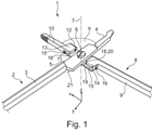
- FIG. 1 shows a medical instrument 1 of a first exemplary embodiment in a perspective view, which comprises a first hand lever 2, which is essentially made up of three sections: a handle section 3, a working section 4 and a bearing section 5.
- the handle section 3 is located at a proximal end of the first hand lever 2 and is used for manual actuation by a user, such as a surgeon or operator or doctor.
- the working section 4 is designed in the manner of a branch and is used to grip, clamp or cut an object, such as tissue of a patient, and is located at a distal end of the first hand lever 2.
- the bearing section 5 which essentially serves to connect the first hand lever 2 by means of a male bearing element 6 to a second hand lever 8 so as to be pivotable about a common axis of rotation 7.
- the second hand lever 8 comprises a handle section 9, a working section 10 and a guide section 11.
- the handle section 9 is located analogously to the handle section 3 of the first hand lever 2, at a proximal end of the second hand lever 8 and the working section 10 is located at a distal end of the second hand lever 8.
- the guide section 11 is arranged between the handle section 9 and the working section 10.
- the guide section 11 has an insertion recess 12 on one side, which enables the bearing section 5 to be inserted in a cleaning or assembly position (as in 1 shown) is easy to assemble and in a working or operating position (see 2 ) by means of two guide projections 13, 14, which are located distally and proximally of the insertion recess 12, at least partially cover the bearing section 5 and thus guide the first hand lever 2 relative to the second hand lever 8.
- the assembly or cleaning position corresponds to a position in which a relative pivoting angle a, measured between the two working sections 4, 10, is selected such that the bearing section 5 is not in engagement with the guide projections 13, 14, or by these is not covered.
- This corresponds to such a relative position of the two hand levers 2 , 8 to one another that the first hand lever 2 can be easily connected to the second hand lever 8 or mounted thereon in the area of the bearing section 5 with the aid of the bearing element 6 .
- a working or operating position of the medical instrument 1, as in 2 shown, describes a position or all positions at a predetermined angle (within an angular range) in which the first hand lever 2 is guided relative to the second hand lever 8 by means of the bearing section 5 through the guide projections 13, 14.
- an object such as human tissue is grasped, clamped or cut.
- the relative pivotability of the two hand levers 2, 8 can be limited by means of a locking mechanism (not shown here), which is provided, for example, on the proximal ends of the respective handle section 3, 9. This can ensure that the operator cannot unintentionally bring the medical instrument 1 into the assembly and cleaning position during operation/use.
- the guide projections 13, 14 have outer edges 15 running on both sides in the longitudinal direction of the second hand lever 8, which are at least one-fifth, preferably one-fourth, as long as the length of the insertion recess 12, as a result of which reliable guidance of the bearing section 5 over the entire operating range is possible .
- the length of the insertion recess 12 is greater than the width of the first hand lever 2 in the area of the bearing element 6. This ensures that the medical instrument 1 can be assembled and disassembled easily.
- the length of the insertion recess 12 is seen in the longitudinal direction of the second hand lever 8 and corresponds to the X-direction of the coordinate system 1 .
- the longitudinal direction of the first hand lever 2 corresponds to 1 the Y-direction and the width of the first hand lever 2 extends in the XY-plane, which corresponds to the pivoting plane of the medical instrument 1, along the X-direction (perpendicular to the Y-direction).
- a thickness of each portion of the first hand lever 2 and the second hand lever 8 extends in the Z direction of the shown coordinate system.
- the thickness of the bearing section 5 is smaller than the height of a guide gap 16, which is formed between an inner surface 17 of the guide projections 13, 14 and a surface of a so-called connecting arm 19 of the guide section 11 that faces it.
- the surface is an inner surface 18 of the connecting arm 19 and serves, in particular in the operating position, as a guiding and contact surface 20 which corresponds to a contact surface 21 (lower surface in 1 ) of the bearing portion 5, these two contact surfaces 20, 21 slidingly touching each other in the operative position.
- the guide projections 13, 14 each have an edge 22 facing the insertion recess 12 (see 2 ) on, which preferably, as e.g. in 1 and 2 shown, convex, crowned or rounded.
- the working sections 4, 10 can, as in 1 and 2 shown, be formed differently, but can alternatively be formed the same.
- the working sections 4, 10, as shown here, are only to be seen as examples and other forms of the working sections 4, 10 are also conceivable.
- 3 and 4 show a second exemplary embodiment of the medical instrument 1.
- This second exemplary embodiment provides that the contact surfaces 20, 21 (see 4 ) now no longer touch, since a spacing-causing element 23 is positioned between them, which spaces the contact surfaces 20, 21 from one another.
- 3 shows the medical instrument 1 of the second exemplary embodiment in the assembly and cleaning position, wherein 3 essentially 1 is equivalent to. The difference between the in 1 shown first exemplary embodiment and in 3 shown second exemplary embodiment is only by the in 4 view shown.
- the bearing element 6 is designed as a screw 24 .
- Alternative embodiments of the bearing element 6 also provide, for example, a rivet.
- connecting elements as a bearing element 6, such as a pin (see also 14 and 15 ), conceivable.
- the space-causing element 23 is designed as a resistance-forming element in the form of a separate ring 25 .
- the spacing-causing element 23 can also be designed as an integrally designed ring, for example in the form of a circumferential collar, or as webs designed on both sides of the bearing element 6 .
- One advantage of the separate component is, among other things, the easy exchangeability of the spacing-causing element 23, which makes it possible to vary the spacing between the guide section 11 and the bearing section 5 by using different spacing-causing elements.
- the spacing-causing element 23 can also, as exemplified in a fourth embodiment (see FIG 8 and 9 ) shown, as a force-applying element, for example.
- a force-applying element In the form of a leaf spring 26 may be formed.
- Such force-applying elements also include other types of springs, such as a plate spring or a spiral spring, and also magnets, in which case the magnetic repulsion is used to space the bearing section 5 and the inner surface 18 of the guide section 11, or alternatively a pressure tank is also possible.
- a thermally active element is also conceivable, which expands, for example, from a certain temperature and thus leads to spacing.
- the Figs. 10 to 13 show a fifth exemplary embodiment of the medical instrument 1, in which a distance-causing element 23 is provided, which enables a targeted manual adjustability of the height (seen along/in the direction of the axis of rotation 7) of the cleaning gap 27.
- a distance-causing element 23 is provided, which enables a targeted manual adjustability of the height (seen along/in the direction of the axis of rotation 7) of the cleaning gap 27.
- 10 shows 10 a top view of the fifth exemplary embodiment of the medical instrument 1 in the assembly and cleaning position, which essentially corresponds to that in 1 and 3 corresponds to the illustrations shown.
- the clearance causing member 23 provided in this embodiment is formed such that on the connecting arm 19 (see FIG 11 ) A spacer sleeve 28 is attached, into which the bearing element 6, which is designed as a screw 24, can be screwed.
- the spacer sleeve 28 has an internal thread in its interior, into which the screw 24 can be screwed/turned.
- a spiral spring 29 in the spacer sleeve 28 which is arranged in a pot 30 formed inside the spacer sleeve 28, the pot 30 having a larger inside diameter than the outside diameter of the internal thread.
- the spiral spring 29 rests with one end on the base/bottom of the pot 30 and with the other end on the outside 31 of the connecting arm 19 .
- the height of the cleaning gap 27 can be specifically adjusted via the screwing depth of the bearing element 6 into the internal thread of the spacer sleeve 28 and the force produced by the prestressing of the spiral spring 29 and acting on the outside 31 of the connecting arm 19 .
- Figs. 5 to 7 as well as the Figs. 14 and 15 show a third and sixth exemplary embodiment, which in each case provides a connection of the hand levers 2, 8 that can be dismantled without tools.
- the third exemplary embodiment shown here provides a bearing 32 in the manner of a bayonet catch 33 (see 7 ).
- the second hand lever 8 has as a guide section 11 a guide section 34 that is essentially circular/round in the XY plane.
- the Leading Section 34 has a guide gap 35 running in the circumferential direction, which is formed by a guide projection 36 running in the circumferential direction, the guide projection 36 extending radially inward from an outer circumference of the guide section 34 .
- the circumferential guide gap 35 or the circumferential guide projection 36 is defined by at least one, preferably several (in figure 5 , four), recesses 37 are interrupted, which are preferably arranged evenly distributed along the circumferential direction.
- the first hand lever 2 shown comprises the handle section 3 and the working section 4, as is already known from the other embodiments.
- the bearing section 5 in the form of a in the XY plane 6
- Substantially circular or round bearing section 38 which is the counterpart to the in figure 5 shown guide portion 34 forms.
- the bearing element 6 is provided integrally in the bearing section 38 and is also referred to below as the bearing element 39 .
- the bearing element 39 is formed in a substantially circular shape in the XY plane, extends along a height direction (Z direction in 6 ) and has a smaller outer diameter than the bearing section 38.
- This circular bearing element 39 has at least one, preferably several, e.g. 2, 3, 4, 5 or 6 (in 6 , Four) projections or projections 40 which extend from an outer circumference of the bearing element 39 radially outwards.
- the number of projections 40 present and their positioning along the circumference corresponds to the number and positioning of the respective recesses 37 on the guide section 34.
- the guide section 34 and the bearing section 38 are matched to one another in such a way that they engage in one another in a form-fitting manner and by relative rotation of the two hand levers 2, 8 a bayonet catch 33 (see 7 ) is realized.
- the operating position extends over the area that is defined by the guide projections 36 . That is, the adjustment angle ⁇ is dependent on the number and positioning of the guide projections 36 and the recesses 37. In FIG Figures 5 to 7 In the exemplary embodiment shown, the adjustment angle ⁇ is, for example, less than 90°. However, if the projections 40 are not evenly distributed (and, as a result, the recesses 37 are also not evenly distributed), a larger adjustment angle ⁇ (for example greater than 90°) can be implemented. Alternatively, it is also conceivable to design the projections 40 in different ways, so that not every projection fits into every recess 37 .
- the projections 40 shown in this embodiment are formed in a trapezoidal shape.
- other geometric shapes such as a pin or a triangular shape, etc., are also conceivable which, in combination with the correspondingly designed recesses 37 on the guide section 34, enable the two hand levers 2, 8 to be connected in the manner of a bayonet catch.
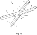
- 14 and 15 show a sixth exemplary embodiment, which essentially corresponds to that in 1 and 2 corresponds to the first embodiment shown, with the difference that only a pin 41 is provided as a bearing element 6 .
- This is here formed integrally with the second hand lever 8 and is pushed through or inserted through a hole 42 during assembly of the medical instrument 1 in the assembly and cleaning position, which is located in the bearing section 5 of the first hand lever 2 .
- the two hand levers 2, 8 are moved by means of the guide projections 13, 14 (see 15 ) relative to each other.
- the two hand levers 2, 8 can be separated from one another without tools, which corresponds to a tool-free disassembly of the medical instrument 1, e.g. for cleaning and sterilization.
- the bearing element 6 can also be provided as a separately formed pin, for example in the form of a threaded pin, which can then be screwed into a thread provided on the guide section 11 .
Landscapes
- Health & Medical Sciences (AREA)
- Life Sciences & Earth Sciences (AREA)
- Engineering & Computer Science (AREA)
- Surgery (AREA)
- Medical Informatics (AREA)
- Nuclear Medicine, Radiotherapy & Molecular Imaging (AREA)
- Biomedical Technology (AREA)
- Heart & Thoracic Surgery (AREA)
- Ophthalmology & Optometry (AREA)
- Molecular Biology (AREA)
- Animal Behavior & Ethology (AREA)
- General Health & Medical Sciences (AREA)
- Public Health (AREA)
- Veterinary Medicine (AREA)
- Mechanical Engineering (AREA)
- Surgical Instruments (AREA)
- Dental Tools And Instruments Or Auxiliary Dental Instruments (AREA)
Claims (7)
- Instrument médical (1), comprenant un premier levier manuel (2), qui présente une section de prise manuelle (3) prévue pour être actionnée à la main au niveau de son extrémité proximale, une section de travail (4) pour saisir, serrer ou couper un objet au niveau de son extrémité distale et une section de palier intermédiaire (38), sur lequel un élément de support mâle (39 ; 41) entre en prise, pour permettre un pivotement autour d'un axe de rotation (7) entre le premier levier manuel (2) et un second levier manuel (8), dans lequel le second levier manuel (8) présente une section de prise manuelle (9) au niveau de son extrémité proximale, une section de travail (10) au niveau de son extrémité distale et une section de guidage intermédiaire (34), sur laquelle l'élément de support (39 ; 41) entre en prise, dans lequel un support (32) est réalisé de telle manière que les deux leviers manuels (2, 8) sont montés par liaison de forme, mais pouvant pivoter l'un par rapport à l'autre, dans une position de fonctionnement au moyen de l'élément de support (39 ; 41), et que les leviers manuels (2, 8) peuvent être démontés sans outil dans une position de nettoyage, dans lequel dans la section de support (38) du premier levier (2) l'élément de support mâle (39 ; 41) est prévu en une seule pièce et dans lequel la section de guidage (34) du second levier manuel (8) est réalisée de manière ronde et présente une fente de guidage (35) s'étendant en direction circonférentielle, réalisée au niveau de la circonférence extérieure de la section de guidage (34), caractérisé en ce que la fente de guidage (35) circonférentielle est interrompue par plusieurs évidement (37) répartis dans la direction circonférentielle.
- Instrument médical (1) selon la revendication 1, caractérisé en ce que le support (32) est réalisé à la manière d'une serrure à baïonnette (33).
- Instrument médical (1) selon la revendication 1 ou 2, caractérisé en ce que l'élément de support (39) est réalisé de manière et présente 2, 3, 4, 5 ou 6 saillies (40) réparties dans la direction circonférentielle.
- Instrument médical (1) selon l'une quelconque des revendications 1 à 3, caractérisé en ce que les saillies (40) sont réalisées de forme trapézoïdale.
- Instrument médical (1) selon la revendication 4, caractérisé en ce que les saillies (40) de forme trapézoïdale présentent un bord latéral plus long radialement vers l'extérieur que radialement vers l'intérieur.
- Instrument médical (1) selon l'une quelconque des revendications 3 à 5, caractérisé en ce que le nombre et la position le long de la circonférence des saillies (40) respectives correspondent au nombre et à la position le long de la circonférence des évidements (37) respectifs.
- Instrument médical (1) selon l'une quelconque des revendications 3 à 6, caractérisé en ce que quatre évidements (37) sont prévus, lesquels sont disposés de manière à être répartis de manière uniforme sur la circonférence.
Applications Claiming Priority (1)
| Application Number | Priority Date | Filing Date | Title |
|---|---|---|---|
| DE102016116623.5A DE102016116623A1 (de) | 2016-09-06 | 2016-09-06 | Werkzeuglos montierbares/demontierbares medizinisches Instrument |
Publications (2)
| Publication Number | Publication Date |
|---|---|
| EP3289987A1 EP3289987A1 (fr) | 2018-03-07 |
| EP3289987B1 true EP3289987B1 (fr) | 2022-01-19 |
Family
ID=59811109
Family Applications (1)
| Application Number | Title | Priority Date | Filing Date |
|---|---|---|---|
| EP17189576.6A Active EP3289987B1 (fr) | 2016-09-06 | 2017-09-06 | Instrument médical montable/démontable sans outils |
Country Status (3)
| Country | Link |
|---|---|
| EP (1) | EP3289987B1 (fr) |
| DE (1) | DE102016116623A1 (fr) |
| ES (1) | ES2909457T3 (fr) |
Families Citing this family (2)
| Publication number | Priority date | Publication date | Assignee | Title |
|---|---|---|---|---|
| DE102021106110A1 (de) * | 2021-03-12 | 2022-09-15 | Aesculap Ag | Aufnahme-Expanderhülse sowie Werkzeugset |
| DE102021209440A1 (de) | 2021-08-27 | 2023-03-02 | Aesculap Ag | Medizinisches Instrument |
Family Cites Families (10)
| Publication number | Priority date | Publication date | Assignee | Title |
|---|---|---|---|---|
| DE86128C (de) * | 1895-06-16 | 1896-04-04 | Feinmechanik Ag | Verdeckt liegender, zerlegbarer verschlufs für scheeren, zangen |
| DE836548C (de) * | 1946-06-28 | 1952-04-15 | Henri Van Steenbrugghe | Gelenkstueck fuer chirurgische Instrumente od. dgl. |
| US5232360A (en) * | 1991-09-16 | 1993-08-03 | Luis Ingels | Orthodontic pliers |
| GB2280397A (en) * | 1993-07-16 | 1995-02-01 | Edward Hampshire | Pivoted hand instrument |
| DE202004002560U1 (de) * | 2004-02-19 | 2004-04-22 | Helmut Zepf Medizintechnik Gmbh | Dentalmedizinische Zange |
| DE102008058207A1 (de) * | 2008-11-19 | 2010-05-20 | Dannoritzer Medizintechnik Gmbh & Co. Kg | Handgriffvorrichtung |
| DE202009002367U1 (de) * | 2009-02-19 | 2009-07-16 | Kohdent Roland Kohler Medizintechnik Gmbh & Co. Kg | Medizinisches Instrument, insbesondere Zange aus zwei Hälften |
| DE202010010843U1 (de) | 2010-07-29 | 2010-11-04 | Richard Martin Medizintechnik Gmbh | Medizinisches Handwerkzeug |
| DE202011107977U1 (de) | 2011-11-17 | 2011-11-30 | Innovations-Medical Gmbh | Medizinisches Instrument |
| DE202013010321U1 (de) | 2013-11-14 | 2014-01-15 | Innovations-Medical Gmbh | Zangenartiges medizinisches Instrument |
-
2016
- 2016-09-06 DE DE102016116623.5A patent/DE102016116623A1/de not_active Withdrawn
-
2017
- 2017-09-06 EP EP17189576.6A patent/EP3289987B1/fr active Active
- 2017-09-06 ES ES17189576T patent/ES2909457T3/es active Active
Also Published As
| Publication number | Publication date |
|---|---|
| EP3289987A1 (fr) | 2018-03-07 |
| DE102016116623A1 (de) | 2018-03-08 |
| ES2909457T3 (es) | 2022-05-06 |
Similar Documents
| Publication | Publication Date | Title |
|---|---|---|
| EP3509510B1 (fr) | Instrument médical présentant une fente de nettoyage dans la zone de verrouillage | |
| EP3169254B1 (fr) | Dispositif de positionnement pour fixer un clou intramédullaire dans un os long | |
| EP2594210B1 (fr) | Instrument médical | |
| DE102004012109B3 (de) | Analspreizer | |
| EP2561816B1 (fr) | Outil pour un instrument chirurgical micro-invasif | |
| EP3000404B1 (fr) | Instrument medical et dispositif de liaison destine a relier deux composants d'un instrument medical | |
| EP2510889B1 (fr) | Dispositif de manipulation pour un instrument de chirurgie micro-invasive | |
| EP2434940A1 (fr) | Dispositif de commande | |
| DE102011001973A1 (de) | Steuerungsvorrichtung | |
| DE102014109935B4 (de) | Positioniervorrichtung zum Fixieren eines Marknagels in einem Röhrenknochen | |
| DE112014005620T5 (de) | Chirurgisches Retraktorsystem und Verfahren | |
| EP3289987B1 (fr) | Instrument médical montable/démontable sans outils | |
| DE202011000848U1 (de) | Steuerungsvorrichtung | |
| EP3551104B1 (fr) | Instrument de repositionnement chirurgical | |
| WO2017216039A1 (fr) | Instrument chirurgical présentant un élément pivotant de conservation de la distance | |
| EP3250133B1 (fr) | Instrument d'arbre pour buts chirurgicals | |
| DE102016116627A1 (de) | Einfach montierbares / demontierbares medizinisches Handwerkzeug | |
| DE102015114264A1 (de) | Mikroinvasives medizinisches Instrument | |
| DE202007000427U1 (de) | Chirurgischer Haltegriff und chirurgisches Instrument | |
| DE102022116372B4 (de) | Chirurgisches instrument und verfahren zu dessen zerlegung | |
| EP3178419B1 (fr) | Dispositif d'accouplement pour un instrument médical démontable | |
| DE102024111699A1 (de) | Chirurgisches Schaftinstrument sowie Verfahren zum Herstellen eines chirurgischen Schaftsinstruments | |
| DE4441595A1 (de) | Nadelhalter für eine chirurgische Nadel | |
| DE102021105418A1 (de) | Operationsinstrument | |
| DE102011000928A1 (de) | Chirurgisches Instrument und Verfahren zum Herstellen eines chirurgischen Instruments |
Legal Events
| Date | Code | Title | Description |
|---|---|---|---|
| PUAI | Public reference made under article 153(3) epc to a published international application that has entered the european phase |
Free format text: ORIGINAL CODE: 0009012 |
|
| STAA | Information on the status of an ep patent application or granted ep patent |
Free format text: STATUS: THE APPLICATION HAS BEEN PUBLISHED |
|
| AK | Designated contracting states |
Kind code of ref document: A1 Designated state(s): AL AT BE BG CH CY CZ DE DK EE ES FI FR GB GR HR HU IE IS IT LI LT LU LV MC MK MT NL NO PL PT RO RS SE SI SK SM TR |
|
| AX | Request for extension of the european patent |
Extension state: BA ME |
|
| STAA | Information on the status of an ep patent application or granted ep patent |
Free format text: STATUS: REQUEST FOR EXAMINATION WAS MADE |
|
| 17P | Request for examination filed |
Effective date: 20180905 |
|
| RBV | Designated contracting states (corrected) |
Designated state(s): AL AT BE BG CH CY CZ DE DK EE ES FI FR GB GR HR HU IE IS IT LI LT LU LV MC MK MT NL NO PL PT RO RS SE SI SK SM TR |
|
| GRAP | Despatch of communication of intention to grant a patent |
Free format text: ORIGINAL CODE: EPIDOSNIGR1 |
|
| STAA | Information on the status of an ep patent application or granted ep patent |
Free format text: STATUS: GRANT OF PATENT IS INTENDED |
|
| RIC1 | Information provided on ipc code assigned before grant |
Ipc: A61B 17/28 20060101AFI20210720BHEP Ipc: A61B 17/3201 20060101ALI20210720BHEP Ipc: A61B 90/70 20160101ALN20210720BHEP Ipc: A61B 17/00 20060101ALN20210720BHEP Ipc: B25B 7/02 20060101ALN20210720BHEP Ipc: B25B 7/08 20060101ALN20210720BHEP Ipc: A61B 90/00 20160101ALN20210720BHEP |
|
| INTG | Intention to grant announced |
Effective date: 20210818 |
|
| GRAS | Grant fee paid |
Free format text: ORIGINAL CODE: EPIDOSNIGR3 |
|
| GRAA | (expected) grant |
Free format text: ORIGINAL CODE: 0009210 |
|
| STAA | Information on the status of an ep patent application or granted ep patent |
Free format text: STATUS: THE PATENT HAS BEEN GRANTED |
|
| AK | Designated contracting states |
Kind code of ref document: B1 Designated state(s): AL AT BE BG CH CY CZ DE DK EE ES FI FR GB GR HR HU IE IS IT LI LT LU LV MC MK MT NL NO PL PT RO RS SE SI SK SM TR |
|
| RAP3 | Party data changed (applicant data changed or rights of an application transferred) |
Owner name: KARL LEIBINGER MEDIZINTECHNIK GMBH & CO. KG |
|
| REG | Reference to a national code |
Ref country code: GB Ref legal event code: FG4D Free format text: NOT ENGLISH |
|
| REG | Reference to a national code |
Ref country code: CH Ref legal event code: EP |
|
| REG | Reference to a national code |
Ref country code: DE Ref legal event code: R096 Ref document number: 502017012465 Country of ref document: DE |
|
| REG | Reference to a national code |
Ref country code: AT Ref legal event code: REF Ref document number: 1463324 Country of ref document: AT Kind code of ref document: T Effective date: 20220215 |
|
| REG | Reference to a national code |
Ref country code: IE Ref legal event code: FG4D Free format text: LANGUAGE OF EP DOCUMENT: GERMAN |
|
| REG | Reference to a national code |
Ref country code: ES Ref legal event code: FG2A Ref document number: 2909457 Country of ref document: ES Kind code of ref document: T3 Effective date: 20220506 |
|
| REG | Reference to a national code |
Ref country code: LT Ref legal event code: MG9D |
|
| REG | Reference to a national code |
Ref country code: NL Ref legal event code: MP Effective date: 20220119 |
|
| PG25 | Lapsed in a contracting state [announced via postgrant information from national office to epo] |
Ref country code: NL Free format text: LAPSE BECAUSE OF FAILURE TO SUBMIT A TRANSLATION OF THE DESCRIPTION OR TO PAY THE FEE WITHIN THE PRESCRIBED TIME-LIMIT Effective date: 20220119 |
|
| PG25 | Lapsed in a contracting state [announced via postgrant information from national office to epo] |
Ref country code: SE Free format text: LAPSE BECAUSE OF FAILURE TO SUBMIT A TRANSLATION OF THE DESCRIPTION OR TO PAY THE FEE WITHIN THE PRESCRIBED TIME-LIMIT Effective date: 20220119 Ref country code: RS Free format text: LAPSE BECAUSE OF FAILURE TO SUBMIT A TRANSLATION OF THE DESCRIPTION OR TO PAY THE FEE WITHIN THE PRESCRIBED TIME-LIMIT Effective date: 20220119 Ref country code: PT Free format text: LAPSE BECAUSE OF FAILURE TO SUBMIT A TRANSLATION OF THE DESCRIPTION OR TO PAY THE FEE WITHIN THE PRESCRIBED TIME-LIMIT Effective date: 20220519 Ref country code: NO Free format text: LAPSE BECAUSE OF FAILURE TO SUBMIT A TRANSLATION OF THE DESCRIPTION OR TO PAY THE FEE WITHIN THE PRESCRIBED TIME-LIMIT Effective date: 20220419 Ref country code: LT Free format text: LAPSE BECAUSE OF FAILURE TO SUBMIT A TRANSLATION OF THE DESCRIPTION OR TO PAY THE FEE WITHIN THE PRESCRIBED TIME-LIMIT Effective date: 20220119 Ref country code: HR Free format text: LAPSE BECAUSE OF FAILURE TO SUBMIT A TRANSLATION OF THE DESCRIPTION OR TO PAY THE FEE WITHIN THE PRESCRIBED TIME-LIMIT Effective date: 20220119 Ref country code: BG Free format text: LAPSE BECAUSE OF FAILURE TO SUBMIT A TRANSLATION OF THE DESCRIPTION OR TO PAY THE FEE WITHIN THE PRESCRIBED TIME-LIMIT Effective date: 20220419 |
|
| PG25 | Lapsed in a contracting state [announced via postgrant information from national office to epo] |
Ref country code: PL Free format text: LAPSE BECAUSE OF FAILURE TO SUBMIT A TRANSLATION OF THE DESCRIPTION OR TO PAY THE FEE WITHIN THE PRESCRIBED TIME-LIMIT Effective date: 20220119 Ref country code: LV Free format text: LAPSE BECAUSE OF FAILURE TO SUBMIT A TRANSLATION OF THE DESCRIPTION OR TO PAY THE FEE WITHIN THE PRESCRIBED TIME-LIMIT Effective date: 20220119 Ref country code: GR Free format text: LAPSE BECAUSE OF FAILURE TO SUBMIT A TRANSLATION OF THE DESCRIPTION OR TO PAY THE FEE WITHIN THE PRESCRIBED TIME-LIMIT Effective date: 20220420 Ref country code: FI Free format text: LAPSE BECAUSE OF FAILURE TO SUBMIT A TRANSLATION OF THE DESCRIPTION OR TO PAY THE FEE WITHIN THE PRESCRIBED TIME-LIMIT Effective date: 20220119 |
|
| PG25 | Lapsed in a contracting state [announced via postgrant information from national office to epo] |
Ref country code: IS Free format text: LAPSE BECAUSE OF FAILURE TO SUBMIT A TRANSLATION OF THE DESCRIPTION OR TO PAY THE FEE WITHIN THE PRESCRIBED TIME-LIMIT Effective date: 20220519 |
|
| REG | Reference to a national code |
Ref country code: DE Ref legal event code: R097 Ref document number: 502017012465 Country of ref document: DE |
|
| PG25 | Lapsed in a contracting state [announced via postgrant information from national office to epo] |
Ref country code: SM Free format text: LAPSE BECAUSE OF FAILURE TO SUBMIT A TRANSLATION OF THE DESCRIPTION OR TO PAY THE FEE WITHIN THE PRESCRIBED TIME-LIMIT Effective date: 20220119 Ref country code: SK Free format text: LAPSE BECAUSE OF FAILURE TO SUBMIT A TRANSLATION OF THE DESCRIPTION OR TO PAY THE FEE WITHIN THE PRESCRIBED TIME-LIMIT Effective date: 20220119 Ref country code: RO Free format text: LAPSE BECAUSE OF FAILURE TO SUBMIT A TRANSLATION OF THE DESCRIPTION OR TO PAY THE FEE WITHIN THE PRESCRIBED TIME-LIMIT Effective date: 20220119 Ref country code: EE Free format text: LAPSE BECAUSE OF FAILURE TO SUBMIT A TRANSLATION OF THE DESCRIPTION OR TO PAY THE FEE WITHIN THE PRESCRIBED TIME-LIMIT Effective date: 20220119 Ref country code: DK Free format text: LAPSE BECAUSE OF FAILURE TO SUBMIT A TRANSLATION OF THE DESCRIPTION OR TO PAY THE FEE WITHIN THE PRESCRIBED TIME-LIMIT Effective date: 20220119 Ref country code: CZ Free format text: LAPSE BECAUSE OF FAILURE TO SUBMIT A TRANSLATION OF THE DESCRIPTION OR TO PAY THE FEE WITHIN THE PRESCRIBED TIME-LIMIT Effective date: 20220119 |
|
| PLBE | No opposition filed within time limit |
Free format text: ORIGINAL CODE: 0009261 |
|
| STAA | Information on the status of an ep patent application or granted ep patent |
Free format text: STATUS: NO OPPOSITION FILED WITHIN TIME LIMIT |
|
| PG25 | Lapsed in a contracting state [announced via postgrant information from national office to epo] |
Ref country code: AL Free format text: LAPSE BECAUSE OF FAILURE TO SUBMIT A TRANSLATION OF THE DESCRIPTION OR TO PAY THE FEE WITHIN THE PRESCRIBED TIME-LIMIT Effective date: 20220119 |
|
| 26N | No opposition filed |
Effective date: 20221020 |
|
| PG25 | Lapsed in a contracting state [announced via postgrant information from national office to epo] |
Ref country code: SI Free format text: LAPSE BECAUSE OF FAILURE TO SUBMIT A TRANSLATION OF THE DESCRIPTION OR TO PAY THE FEE WITHIN THE PRESCRIBED TIME-LIMIT Effective date: 20220119 |
|
| PG25 | Lapsed in a contracting state [announced via postgrant information from national office to epo] |
Ref country code: MC Free format text: LAPSE BECAUSE OF FAILURE TO SUBMIT A TRANSLATION OF THE DESCRIPTION OR TO PAY THE FEE WITHIN THE PRESCRIBED TIME-LIMIT Effective date: 20220119 |
|
| REG | Reference to a national code |
Ref country code: CH Ref legal event code: PL |
|
| REG | Reference to a national code |
Ref country code: BE Ref legal event code: MM Effective date: 20220930 |
|
| PG25 | Lapsed in a contracting state [announced via postgrant information from national office to epo] |
Ref country code: LU Free format text: LAPSE BECAUSE OF NON-PAYMENT OF DUE FEES Effective date: 20220906 |
|
| P01 | Opt-out of the competence of the unified patent court (upc) registered |
Effective date: 20230605 |
|
| PG25 | Lapsed in a contracting state [announced via postgrant information from national office to epo] |
Ref country code: LI Free format text: LAPSE BECAUSE OF NON-PAYMENT OF DUE FEES Effective date: 20220930 Ref country code: IE Free format text: LAPSE BECAUSE OF NON-PAYMENT OF DUE FEES Effective date: 20220906 Ref country code: CH Free format text: LAPSE BECAUSE OF NON-PAYMENT OF DUE FEES Effective date: 20220930 |
|
| PG25 | Lapsed in a contracting state [announced via postgrant information from national office to epo] |
Ref country code: BE Free format text: LAPSE BECAUSE OF NON-PAYMENT OF DUE FEES Effective date: 20220930 |
|
| REG | Reference to a national code |
Ref country code: AT Ref legal event code: MM01 Ref document number: 1463324 Country of ref document: AT Kind code of ref document: T Effective date: 20220906 |
|
| PG25 | Lapsed in a contracting state [announced via postgrant information from national office to epo] |
Ref country code: AT Free format text: LAPSE BECAUSE OF NON-PAYMENT OF DUE FEES Effective date: 20220906 |
|
| PG25 | Lapsed in a contracting state [announced via postgrant information from national office to epo] |
Ref country code: HU Free format text: LAPSE BECAUSE OF FAILURE TO SUBMIT A TRANSLATION OF THE DESCRIPTION OR TO PAY THE FEE WITHIN THE PRESCRIBED TIME-LIMIT; INVALID AB INITIO Effective date: 20170906 |
|
| PG25 | Lapsed in a contracting state [announced via postgrant information from national office to epo] |
Ref country code: CY Free format text: LAPSE BECAUSE OF FAILURE TO SUBMIT A TRANSLATION OF THE DESCRIPTION OR TO PAY THE FEE WITHIN THE PRESCRIBED TIME-LIMIT Effective date: 20220119 |
|
| PG25 | Lapsed in a contracting state [announced via postgrant information from national office to epo] |
Ref country code: MK Free format text: LAPSE BECAUSE OF FAILURE TO SUBMIT A TRANSLATION OF THE DESCRIPTION OR TO PAY THE FEE WITHIN THE PRESCRIBED TIME-LIMIT Effective date: 20220119 |
|
| PG25 | Lapsed in a contracting state [announced via postgrant information from national office to epo] |
Ref country code: MT Free format text: LAPSE BECAUSE OF FAILURE TO SUBMIT A TRANSLATION OF THE DESCRIPTION OR TO PAY THE FEE WITHIN THE PRESCRIBED TIME-LIMIT Effective date: 20220119 |
|
| REG | Reference to a national code |
Ref country code: DE Ref legal event code: R082 Ref document number: 502017012465 Country of ref document: DE Ref country code: DE Ref legal event code: R081 Ref document number: 502017012465 Country of ref document: DE Owner name: KARL LEIBINGER ASSET MANAGEMENT GMBH & CO. KG, DE Free format text: FORMER OWNER: KARL LEIBINGER MEDIZINTECHNIK GMBH & CO. KG, 78570 MUEHLHEIM, DE |
|
| REG | Reference to a national code |
Ref country code: GB Ref legal event code: 732E Free format text: REGISTERED BETWEEN 20241031 AND 20241106 |
|
| REG | Reference to a national code |
Ref country code: ES Ref legal event code: PC2A Owner name: KARL LEIBINGER ASSET MANAGEMENT GMBH & CO. KG Effective date: 20241125 |
|
| PGFP | Annual fee paid to national office [announced via postgrant information from national office to epo] |
Ref country code: DE Payment date: 20250919 Year of fee payment: 9 |
|
| PGFP | Annual fee paid to national office [announced via postgrant information from national office to epo] |
Ref country code: GB Payment date: 20250923 Year of fee payment: 9 |
|
| PGFP | Annual fee paid to national office [announced via postgrant information from national office to epo] |
Ref country code: FR Payment date: 20250924 Year of fee payment: 9 |
|
| PG25 | Lapsed in a contracting state [announced via postgrant information from national office to epo] |
Ref country code: TR Free format text: LAPSE BECAUSE OF FAILURE TO SUBMIT A TRANSLATION OF THE DESCRIPTION OR TO PAY THE FEE WITHIN THE PRESCRIBED TIME-LIMIT Effective date: 20220119 |
|
| PGFP | Annual fee paid to national office [announced via postgrant information from national office to epo] |
Ref country code: IT Payment date: 20250930 Year of fee payment: 9 |
|
| PGFP | Annual fee paid to national office [announced via postgrant information from national office to epo] |
Ref country code: ES Payment date: 20251020 Year of fee payment: 9 |