EP3290108A1 - Colonne avec garnissage, procédé d'echange d'énergie et/ou de matière entre une phase gazeuse et une phase liquide et procédé de fabrication du garnissage - Google Patents
Colonne avec garnissage, procédé d'echange d'énergie et/ou de matière entre une phase gazeuse et une phase liquide et procédé de fabrication du garnissage Download PDFInfo
- Publication number
- EP3290108A1 EP3290108A1 EP17020383.0A EP17020383A EP3290108A1 EP 3290108 A1 EP3290108 A1 EP 3290108A1 EP 17020383 A EP17020383 A EP 17020383A EP 3290108 A1 EP3290108 A1 EP 3290108A1
- Authority
- EP
- European Patent Office
- Prior art keywords
- column
- valleys
- mountains
- material layers
- layers
- Prior art date
- Legal status (The legal status is an assumption and is not a legal conclusion. Google has not performed a legal analysis and makes no representation as to the accuracy of the status listed.)
- Withdrawn
Links
- 239000000463 material Substances 0.000 title claims abstract description 83
- 239000007791 liquid phase Substances 0.000 title claims abstract description 25
- 239000007792 gaseous phase Substances 0.000 title claims abstract description 24
- 238000012856 packing Methods 0.000 title claims abstract description 21
- 238000000034 method Methods 0.000 title claims abstract description 12
- 239000000126 substance Substances 0.000 claims description 2
- 210000001072 colon Anatomy 0.000 claims 1
- 238000004519 manufacturing process Methods 0.000 abstract description 9
- 239000007788 liquid Substances 0.000 description 8
- 238000010146 3D printing Methods 0.000 description 4
- 238000009826 distribution Methods 0.000 description 3
- 230000001360 synchronised effect Effects 0.000 description 3
- 238000010894 electron beam technology Methods 0.000 description 2
- 238000000110 selective laser sintering Methods 0.000 description 2
- 238000003892 spreading Methods 0.000 description 2
- 238000012546 transfer Methods 0.000 description 2
- 239000000654 additive Substances 0.000 description 1
- 230000000996 additive effect Effects 0.000 description 1
- 230000004888 barrier function Effects 0.000 description 1
- 230000008021 deposition Effects 0.000 description 1
- 239000007789 gas Substances 0.000 description 1
- 238000003384 imaging method Methods 0.000 description 1
- 238000004372 laser cladding Methods 0.000 description 1
- 238000002844 melting Methods 0.000 description 1
- 230000008018 melting Effects 0.000 description 1
- 238000002156 mixing Methods 0.000 description 1
- 239000012071 phase Substances 0.000 description 1
- 238000012545 processing Methods 0.000 description 1
- 238000013517 stratification Methods 0.000 description 1
Images
Classifications
-
- B—PERFORMING OPERATIONS; TRANSPORTING
- B01—PHYSICAL OR CHEMICAL PROCESSES OR APPARATUS IN GENERAL
- B01J—CHEMICAL OR PHYSICAL PROCESSES, e.g. CATALYSIS OR COLLOID CHEMISTRY; THEIR RELEVANT APPARATUS
- B01J19/00—Chemical, physical or physico-chemical processes in general; Their relevant apparatus
- B01J19/32—Packing elements in the form of grids or built-up elements for forming a unit or module inside the apparatus for mass or heat transfer
-
- B—PERFORMING OPERATIONS; TRANSPORTING
- B01—PHYSICAL OR CHEMICAL PROCESSES OR APPARATUS IN GENERAL
- B01J—CHEMICAL OR PHYSICAL PROCESSES, e.g. CATALYSIS OR COLLOID CHEMISTRY; THEIR RELEVANT APPARATUS
- B01J2219/00—Chemical, physical or physico-chemical processes in general; Their relevant apparatus
- B01J2219/30—Details relating to random packing elements
- B01J2219/302—Basic shape of the elements
- B01J2219/30296—Other shapes
-
- B—PERFORMING OPERATIONS; TRANSPORTING
- B01—PHYSICAL OR CHEMICAL PROCESSES OR APPARATUS IN GENERAL
- B01J—CHEMICAL OR PHYSICAL PROCESSES, e.g. CATALYSIS OR COLLOID CHEMISTRY; THEIR RELEVANT APPARATUS
- B01J2219/00—Chemical, physical or physico-chemical processes in general; Their relevant apparatus
- B01J2219/32—Details relating to packing elements in the form of grids or built-up elements for forming a unit of module inside the apparatus for mass or heat transfer
- B01J2219/322—Basic shape of the elements
- B01J2219/32203—Sheets
- B01J2219/3221—Corrugated sheets
-
- B—PERFORMING OPERATIONS; TRANSPORTING
- B01—PHYSICAL OR CHEMICAL PROCESSES OR APPARATUS IN GENERAL
- B01J—CHEMICAL OR PHYSICAL PROCESSES, e.g. CATALYSIS OR COLLOID CHEMISTRY; THEIR RELEVANT APPARATUS
- B01J2219/00—Chemical, physical or physico-chemical processes in general; Their relevant apparatus
- B01J2219/32—Details relating to packing elements in the form of grids or built-up elements for forming a unit of module inside the apparatus for mass or heat transfer
- B01J2219/322—Basic shape of the elements
- B01J2219/32203—Sheets
- B01J2219/32213—Plurality of essentially parallel sheets
-
- B—PERFORMING OPERATIONS; TRANSPORTING
- B01—PHYSICAL OR CHEMICAL PROCESSES OR APPARATUS IN GENERAL
- B01J—CHEMICAL OR PHYSICAL PROCESSES, e.g. CATALYSIS OR COLLOID CHEMISTRY; THEIR RELEVANT APPARATUS
- B01J2219/00—Chemical, physical or physico-chemical processes in general; Their relevant apparatus
- B01J2219/32—Details relating to packing elements in the form of grids or built-up elements for forming a unit of module inside the apparatus for mass or heat transfer
- B01J2219/322—Basic shape of the elements
- B01J2219/32203—Sheets
- B01J2219/32237—Sheets comprising apertures or perforations
-
- B—PERFORMING OPERATIONS; TRANSPORTING
- B01—PHYSICAL OR CHEMICAL PROCESSES OR APPARATUS IN GENERAL
- B01J—CHEMICAL OR PHYSICAL PROCESSES, e.g. CATALYSIS OR COLLOID CHEMISTRY; THEIR RELEVANT APPARATUS
- B01J2219/00—Chemical, physical or physico-chemical processes in general; Their relevant apparatus
- B01J2219/32—Details relating to packing elements in the form of grids or built-up elements for forming a unit of module inside the apparatus for mass or heat transfer
- B01J2219/322—Basic shape of the elements
- B01J2219/32203—Sheets
- B01J2219/32248—Sheets comprising areas that are raised or sunken from the plane of the sheet
Definitions
- the invention relates to a column for mass and / or energy exchange between a liquid and a gaseous phase, a production method for a packing according to the invention and a method for mass and / or energy exchange between a liquid and a gaseous phase.
- Such packages consist of a structured arrangement of multiple layers of material (e.g., sheets). These material layers according to the prior art often have a primary folding pattern (with a defined folding angle) of (wave) mountains and (wave) valleys, which are connected by means of flanks.
- such material layers often have uniformly distributed over the entire material layer, ie mountains, valleys and flanks, through-holes. These even out gas flow between layers of material (e.g., sheets) but also act as a barrier to liquid flow. The liquid flow splits when it encounters a through hole. This is advantageous because a broadened liquid flow leads to a more uniform utilization of the packing.
- the passage openings are distributed over the entire material layer according to the prior art.
- a first aspect of the invention relates to a column having a packing comprising a plurality of layers of material (eg sheets) arranged in parallel, each extending along a plane, the respective material layer having a plurality of alternately arranged peaks and valleys in each case a mountain is connected to an adjacent valley via a flank, and wherein the respective material layer in each case has a plurality of through openings distributed over the material layer, and wherein the packing in the column for substance and / or energy exchange between a liquid phase and a gaseous Phase is arranged, that the planes along which the material layers extend are each arranged parallel to a column axis or have an inclination with respect to the column cross-section, which is perpendicular to the column axis, wherein the column is adapted to the liquid phase and the gaseous e phase for the respective material layer, the opening ratio of formed by the through holes free opening area to non-through holes covered closed area on the mountains and valleys is greater than on the flanks, and wherein the material layers have
- the mountains or valleys are curved or curved areas of the material layers, which in particular have the largest curvature of the respective material layer.
- the flanks are in particular flat or substantially flat areas of the material layers, each connecting a mountain with a valley.
- the flanks may in particular also have a curvature, in particular the curvatures of the respective flanks (if present) being smaller than the greatest curvature of the mountains or valleys.
- the mountains and valleys of the material layers may alternatively also be referred to as head sections (mountains) or foot sections (valleys) become. A head section is then connected in each case via one flank each to the two adjacent foot sections.
- the mountains and valleys in particular run at an angle of 30 ° to 70 °, e.g. 45 ° or 60 ° to the column axis.
- the through holes are thus arranged in greater density at the mountains and valleys than at the flanks of the respective material layer, that is, at the mountains and valleys, a larger number of through holes per surface of the material layer are arranged as on the flanks.
- the performance of the package is improved because at the through holes of the liquid film in the horizontal and thus radial direction (ie perpendicular to the column axis) is derived and thus there is a better mixing of the liquid and gaseous phase.
- the mountains and valleys of the adjacent material layers run parallel to one another.
- the total aperture ratio of free opening area formed by the passage openings to the closed area on the total area of the material layers, ie on the mountains, valleys and flanks, is 6% to 16%, in particular 11%.
- 70% to 100% of the passage openings are arranged on the mountains and valleys of the material layers. This percentage is based on the total number of through holes on the respective material layer.
- the passage openings of the respective material layer may in particular have a uniform opening area.
- 0% to 30% of the passage openings are arranged on the flanks of the material layers. This percentage is based on the total number of through holes on the respective material layer.
- the passage openings of the respective material layer may in particular have a uniform opening area.
- the passage openings are arranged only on the mountains and valleys, wherein the flanks are free of passage openings.
- the passage openings are circular.
- the material layers have a secondary structure. That is, the surface of the material layers is not completely smooth, but has in addition to the primary structure formed by the mountains and valleys on, in particular regular, structuring or secondary structure.
- This structuring can e.g. be formed by recesses or elevations.
- the recesses may e.g. be formed as notches or grooves.
- the secondary structure is formed by a plurality of grooves extending transversely to the mountains and valleys.
- the improved through the inventive arrangement of the passage openings packing performance is further improved by the secondary structure, which forms in particular transversely to the column axis extending small channels.
- the pack has at least one pack package, which is formed from a plurality of mechanically connected material layers.
- the material layers are arranged individually in the column, wherein they are connected to one another only via the column.
- the material layers form at least one package package, wherein the material layers in the package package are mechanically interconnected.
- both individual material layers and at least one package packet are arranged in the column.
- a further aspect of the invention relates to a method for producing a packing, wherein a plurality of material layers each have a plurality of alternately arranged mountains and valleys, so that in each case one mountain is connected to an adjacent valley via a flank, and in which Material layers each having a plurality of through holes is formed such that the opening ratio of formed by the through holes open area to closed area on the mountains and valleys is greater than on the flanks, in particular the through holes are formed in a planar state of the material layers, wherein forming the passages, the mountains and valleys of the material layers are formed.
- the production is synchronized in particular so that the through holes are introduced at the correct angle and distance of the primary structure. These angles and distances are in particular corrected for the deformations of the sheet, which arise during the Primär Modellfaltung.
- the primary structure fold is synchronized with the perforation, in particular in the production line, so that the passage openings are arranged on the maxima of the fold.
- the generation of the primary structure is synchronized with the previously introduced perforation, i.
- the material layers are printed by means of a 3D printing method, whereby the through-openings, the mountains and the valleys are printed by means of the 3D printing method.
- the passage openings and the mountains and valleys can be formed simultaneously in one production step.
- the material layers can be produced in particular by known 3D printing methods, such as e.g. Selective Laser Sintering (SLS), Electron Beam Melting / Electron Beam Additive Manufacturing (EBM / EBAM), Fused Filament Fabrication (FFF), Melt Stratification (eg Fused Deposition Modeling, FDM), Stereolithography (STL, SLA), Digital Light Processing (DLP) ), Multi Jet Modeling (MJM), Polyjet, Film Transfer Imaging (FTI), laser cladding or Laminated Object Modeling (LOM).
- SLS Selective Laser Sintering
- EBM / EBAM Electron Beam Melting / Electron Beam Additive Manufacturing
- FFF Fused Filament Fabrication
- FDM Melt Stratification
- FDM Melt Stratification
- FDM Melt Stratification
- STL Stereolithography
- SLA Stereolithography
- DLP Digital Light Processing
- MJM Multi Jet Modeling
- Polyjet Film Transfer Imaging
- FI Laser
- Another aspect of the invention relates to a process for mass and / or energy exchange between a liquid phase and a gaseous phase, in particular by means of a column according to the second aspect of the invention, wherein the liquid phase and the gaseous phase in countercurrent by a package after the first aspect of the invention, and wherein the liquid phase is passed predominantly through the packing at the valleys of the material layers.
- the packing is arranged in a column, wherein the liquid phase and the gaseous phase are passed in countercurrent along a column axis through the packing.
- Such columns usually have several layers of packages, which are stacked in particular in the direction of the column axis.
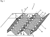
- FIG. 1 a partial perspective view of a material layer 11 according to the invention, for example from a folded sheet, in a Level E is extended.
- the material layer 11 has (eg due to the folding) a primary structure of mountains 12 and valleys 13, wherein the mountains 12 are each connected by means of flanks 14 with adjacent valleys 13.
- the mountains 12 or valleys 13 are curved or curved regions of the material layers 11, which in particular have the greatest curvature of the respective material layer 11.
- the flanks 14 are, in particular, flat or essentially flat regions of the material layers 11, which each connect a mountain 12 to a valley 13.
- the flanks 14 may in particular also have a curvature, wherein in particular the curvatures of the respective flanks 14 (if present) are smaller than the largest curvature of the mountains 12 or valleys 13.
- a boundary between a mountain 12 and the adjacent flanks 14 is in the FIG. 1 exemplified by dashed lines.
- the mountains 12 and valleys 13 extend parallel to one another in an extension direction E 'and can each have a radius of curvature r.
- the wave formed by a mountain 12 or a valley 13 with adjacent flanks 14 has in each case a wavelength s and a wave height h w , wherein the wavelength s is perpendicular to the extension direction E 'along the plane E, and wherein the wave height h w perpendicular to the level E runs. If the plane E in which the material layer 11 extends is arranged parallel to a horizontal, the extension direction E 'of the mountains 12 and valleys 13 extends in particular at an inclination angle ⁇ to the horizontal, the inclination angle ⁇ being in particular 45 °. Adjacent flanks 14 have a wave angle ⁇ in particular at a valley 13 relative to one another.
- the material layer 11 has a plurality of through holes 15, wherein the opening ratio of the formed by the through holes 15 free opening area to the non-through openings covered closed surface of the material layer 11 on the mountains 12 and valleys 13 is greater than on the flanks 14.
- An an The mountains 12 and valleys 13 are thus arranged a larger number of through holes 15 per area than at the flanks 14th
- the material layer 11 also has a secondary structure of grooves 16, the grooves extending transversely to the extension direction E '.
- a packing 10 according to the invention is formed by a plurality of material layers 11 arranged parallel to one another with respect to their plane E.
- the material layers 11 are arranged so that the planes E extend parallel to the column axis a.
- the mountains 12 and valleys 13 extend at an angle, in particular 45 ° or 60 °, to the column axis a.
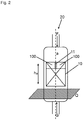
- the FIG. 2 shows a column 20 for energy and / or mass transfer between a liquid phase F and a gaseous phase G with a column axis a and a perpendicular to the column axis a arranged column cross-section Q.
- the column 20 has a packing 10 according to the invention.
- An exemplified position of the pack 10 has two pack packages 100 and a single material layer 11 arranged between the pack packs 100.
- the liquid phase F and the gaseous phase G are in the column 20, e.g. guided in opposite directions, wherein the liquid phase F, the column 20 flows through from top to bottom, and wherein the gaseous phase G, the column 20 flows from bottom to top.
- the liquid phase F and the gaseous phase G are mixed in the package 10.
- the liquid phase F flows for the most part along the valleys 13 of the material layers 11 of the package 10 and thereby passes at least partially through the through-openings 15 arranged on the mountains 12 and valleys 13, which contributes to a better distribution of the liquid phase F.
- the gaseous phase G also flows through the passage openings 15, which contributes to a homogeneous distribution of the gaseous phase G.
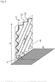
- the FIG. 3 shows an exemplary orientation of a material layer 11 in a column 20.
- the material layer 11 is along a plane E extends, which is parallel to the column axis a, that is perpendicular to the column cross-section Q. Furthermore, an inclination ⁇ between the plane E and the column cross-section Q is shown, wherein the inclination ⁇ is 90 ° in the example shown.
- the mountains 12 and valleys 13 extend obliquely to the column axis a, in particular at an angle of 45 ° to the column axis a.
- the extension direction E 'of the mountains 12 and valleys 13 extends at an angle of inclination ⁇ with respect to the column axis a.
Landscapes
- Chemical & Material Sciences (AREA)
- Physics & Mathematics (AREA)
- Thermal Sciences (AREA)
- Organic Chemistry (AREA)
- Chemical Kinetics & Catalysis (AREA)
- Physical Or Chemical Processes And Apparatus (AREA)
Applications Claiming Priority (1)
| Application Number | Priority Date | Filing Date | Title |
|---|---|---|---|
| EP16001914 | 2016-09-01 |
Publications (1)
| Publication Number | Publication Date |
|---|---|
| EP3290108A1 true EP3290108A1 (fr) | 2018-03-07 |
Family
ID=56883476
Family Applications (1)
| Application Number | Title | Priority Date | Filing Date |
|---|---|---|---|
| EP17020383.0A Withdrawn EP3290108A1 (fr) | 2016-09-01 | 2017-08-24 | Colonne avec garnissage, procédé d'echange d'énergie et/ou de matière entre une phase gazeuse et une phase liquide et procédé de fabrication du garnissage |
Country Status (2)
| Country | Link |
|---|---|
| EP (1) | EP3290108A1 (fr) |
| CN (1) | CN107790098A (fr) |
Cited By (1)
| Publication number | Priority date | Publication date | Assignee | Title |
|---|---|---|---|---|
| DE102021001455A1 (de) | 2021-03-19 | 2022-09-22 | Linde Ag | Packungselement für eine Säule und Verfahren |
Citations (6)
| Publication number | Priority date | Publication date | Assignee | Title |
|---|---|---|---|---|
| US5171544A (en) * | 1988-02-02 | 1992-12-15 | Lang John S | Method of mixing fluids in packing media for reactors |
| EP0807462A1 (fr) * | 1996-05-14 | 1997-11-19 | Air Products And Chemicals, Inc. | Elément de garnissage structuré à texture de surface bi-directionnel et procédé d'échange de matière et chaleur l'utilisant |
| EP1166867A1 (fr) * | 2000-06-30 | 2002-01-02 | Basf Aktiengesellschaft | Garnissage pour des colonnes de transfert de chaleur et de masse |
| WO2003047748A1 (fr) * | 2001-12-06 | 2003-06-12 | Basf Aktiengesellschaft | Oxydes metalliques supportes servant de catalyseurs de condensations aldoliques |
| EP2946822A1 (fr) * | 2014-05-22 | 2015-11-25 | Linde Aktiengesellschaft | Dispositif de séparation permettant de séparer une phase gazeuse d'une phase liquide d'un flux de matière à deux phases |
| DE102014226607A1 (de) * | 2014-12-19 | 2016-06-23 | Technische Universität Dresden | Monolithischer statischer Mischer und/oder katalytisch wirkendes Element sowie Verfahren zur Herstellung |
-
2017
- 2017-08-24 EP EP17020383.0A patent/EP3290108A1/fr not_active Withdrawn
- 2017-08-31 CN CN201710769664.8A patent/CN107790098A/zh active Pending
Patent Citations (6)
| Publication number | Priority date | Publication date | Assignee | Title |
|---|---|---|---|---|
| US5171544A (en) * | 1988-02-02 | 1992-12-15 | Lang John S | Method of mixing fluids in packing media for reactors |
| EP0807462A1 (fr) * | 1996-05-14 | 1997-11-19 | Air Products And Chemicals, Inc. | Elément de garnissage structuré à texture de surface bi-directionnel et procédé d'échange de matière et chaleur l'utilisant |
| EP1166867A1 (fr) * | 2000-06-30 | 2002-01-02 | Basf Aktiengesellschaft | Garnissage pour des colonnes de transfert de chaleur et de masse |
| WO2003047748A1 (fr) * | 2001-12-06 | 2003-06-12 | Basf Aktiengesellschaft | Oxydes metalliques supportes servant de catalyseurs de condensations aldoliques |
| EP2946822A1 (fr) * | 2014-05-22 | 2015-11-25 | Linde Aktiengesellschaft | Dispositif de séparation permettant de séparer une phase gazeuse d'une phase liquide d'un flux de matière à deux phases |
| DE102014226607A1 (de) * | 2014-12-19 | 2016-06-23 | Technische Universität Dresden | Monolithischer statischer Mischer und/oder katalytisch wirkendes Element sowie Verfahren zur Herstellung |
Cited By (1)
| Publication number | Priority date | Publication date | Assignee | Title |
|---|---|---|---|---|
| DE102021001455A1 (de) | 2021-03-19 | 2022-09-22 | Linde Ag | Packungselement für eine Säule und Verfahren |
Also Published As
| Publication number | Publication date |
|---|---|
| CN107790098A (zh) | 2018-03-13 |
Similar Documents
| Publication | Publication Date | Title |
|---|---|---|
| AT505300B1 (de) | Plattenwärmetauscher | |
| DE3622316C1 (de) | Plattenwaermeaustauscher | |
| EP0069241B1 (fr) | Garniture pour colonnes d'échange de matières et procédé de fabrication de la garniture | |
| DE10118625B4 (de) | Wellenförmige Lamelle mit Versatz für Plattenwärmetauscher | |
| EP2199725B1 (fr) | Structure d'un surface avec noyau de refroidissement par impact | |
| DE2443926A1 (de) | Poroeser schichtaufbau und verfahren zu dessen herstellung | |
| DE102013203936A1 (de) | Generatives Schichtaufbauverfahren zur Herstellung eines dreidimensionalen Objekts und dreidimensionales Objekt | |
| DE102013203938A1 (de) | Generatives Schichtaufbauverfahren zur Herstellung eines dreidimensionalen Objekts und dreidimensionales Objekt | |
| EP0671207B1 (fr) | Elément de structure plat et garnissage à partir de cela | |
| DE112018001266B4 (de) | Kühlstruktur für turbinenschaufel | |
| EP1156894A1 (fr) | Metal deploye et outil pour la production de ce dernier | |
| DE112018001282B4 (de) | Kühlstruktur für eine Turbinenschaufel | |
| DE2705123C2 (de) | Wärmetauscher und Verfahren zur Herstellung eines Wärmetauschers | |
| EP3290107A1 (fr) | Emballage, système d'emballage et colonne d'échange d'énergie et/ou de matière entre une phase gazeuse et une phase liquide et procédé de production d'un emballage | |
| EP3290108A1 (fr) | Colonne avec garnissage, procédé d'echange d'énergie et/ou de matière entre une phase gazeuse et une phase liquide et procédé de fabrication du garnissage | |
| DE102017123796B4 (de) | Werkzeug | |
| WO2018210455A1 (fr) | Dispositif de refroidissement, chauffage ou transfert thermique | |
| DE102005010341A1 (de) | Wärmetauscherplatte und Plattenpaket | |
| DE112019001847T5 (de) | Filter für gasgenerator und gasgenerator | |
| DE102018209282B4 (de) | Bauteil, sowie ein Stapel aus einer Mehrzahl solcher Bauteile und ein additives Herstellungsverfahren für einen solchen Stapel | |
| EP3921132B1 (fr) | Bloc de lamelles pour un dispositif d'étalonnage | |
| EP3969129A1 (fr) | Filtre anti-flamme | |
| WO2006034666A1 (fr) | Recuperateur a microcanaux produit a partir de feuilles empilees | |
| WO2019042893A1 (fr) | Système à films gonflable | |
| EP3527357A1 (fr) | Noyau et procédé de fabrication et de traitement ultérieur d'un tel noyau |
Legal Events
| Date | Code | Title | Description |
|---|---|---|---|
| PUAI | Public reference made under article 153(3) epc to a published international application that has entered the european phase |
Free format text: ORIGINAL CODE: 0009012 |
|
| AK | Designated contracting states |
Kind code of ref document: A1 Designated state(s): AL AT BE BG CH CY CZ DE DK EE ES FI FR GB GR HR HU IE IS IT LI LT LU LV MC MK MT NL NO PL PT RO RS SE SI SK SM TR |
|
| AX | Request for extension of the european patent |
Extension state: BA ME |
|
| STAA | Information on the status of an ep patent application or granted ep patent |
Free format text: STATUS: THE APPLICATION IS DEEMED TO BE WITHDRAWN |
|
| 18D | Application deemed to be withdrawn |
Effective date: 20180908 |