EP3290135B1 - Verfahren zur gerichteten rekristallisation von generativ gefertigten metallischen artikeln durch wärmebehandlung mit einem gradientenofen - Google Patents
Verfahren zur gerichteten rekristallisation von generativ gefertigten metallischen artikeln durch wärmebehandlung mit einem gradientenofen Download PDFInfo
- Publication number
- EP3290135B1 EP3290135B1 EP17185425.0A EP17185425A EP3290135B1 EP 3290135 B1 EP3290135 B1 EP 3290135B1 EP 17185425 A EP17185425 A EP 17185425A EP 3290135 B1 EP3290135 B1 EP 3290135B1
- Authority
- EP
- European Patent Office
- Prior art keywords
- metallic article
- metallic
- article
- gradient furnace
- layer
- Prior art date
- Legal status (The legal status is an assumption and is not a legal conclusion. Google has not performed a legal analysis and makes no representation as to the accuracy of the status listed.)
- Active
Links
Images


Classifications
-
- B—PERFORMING OPERATIONS; TRANSPORTING
- B22—CASTING; POWDER METALLURGY
- B22F—WORKING METALLIC POWDER; MANUFACTURE OF ARTICLES FROM METALLIC POWDER; MAKING METALLIC POWDER; APPARATUS OR DEVICES SPECIALLY ADAPTED FOR METALLIC POWDER
- B22F3/00—Manufacture of workpieces or articles from metallic powder characterised by the manner of compacting or sintering; Apparatus specially adapted therefor ; Presses and furnaces
- B22F3/24—After-treatment of workpieces or articles
-
- B—PERFORMING OPERATIONS; TRANSPORTING
- B22—CASTING; POWDER METALLURGY
- B22F—WORKING METALLIC POWDER; MANUFACTURE OF ARTICLES FROM METALLIC POWDER; MAKING METALLIC POWDER; APPARATUS OR DEVICES SPECIALLY ADAPTED FOR METALLIC POWDER
- B22F10/00—Additive manufacturing of workpieces or articles from metallic powder
- B22F10/30—Process control
- B22F10/38—Process control to achieve specific product aspects, e.g. surface smoothness, density, porosity or hollow structures
-
- B—PERFORMING OPERATIONS; TRANSPORTING
- B22—CASTING; POWDER METALLURGY
- B22F—WORKING METALLIC POWDER; MANUFACTURE OF ARTICLES FROM METALLIC POWDER; MAKING METALLIC POWDER; APPARATUS OR DEVICES SPECIALLY ADAPTED FOR METALLIC POWDER
- B22F10/00—Additive manufacturing of workpieces or articles from metallic powder
- B22F10/40—Structures for supporting workpieces or articles during manufacture and removed afterwards
-
- B—PERFORMING OPERATIONS; TRANSPORTING
- B22—CASTING; POWDER METALLURGY
- B22F—WORKING METALLIC POWDER; MANUFACTURE OF ARTICLES FROM METALLIC POWDER; MAKING METALLIC POWDER; APPARATUS OR DEVICES SPECIALLY ADAPTED FOR METALLIC POWDER
- B22F3/00—Manufacture of workpieces or articles from metallic powder characterised by the manner of compacting or sintering; Apparatus specially adapted therefor ; Presses and furnaces
- B22F3/12—Both compacting and sintering
- B22F3/14—Both compacting and sintering simultaneously
- B22F3/15—Hot isostatic pressing
-
- B—PERFORMING OPERATIONS; TRANSPORTING
- B22—CASTING; POWDER METALLURGY
- B22F—WORKING METALLIC POWDER; MANUFACTURE OF ARTICLES FROM METALLIC POWDER; MAKING METALLIC POWDER; APPARATUS OR DEVICES SPECIALLY ADAPTED FOR METALLIC POWDER
- B22F5/00—Manufacture of workpieces or articles from metallic powder characterised by the special shape of the product
- B22F5/009—Manufacture of workpieces or articles from metallic powder characterised by the special shape of the product of turbine components other than turbine blades
-
- B—PERFORMING OPERATIONS; TRANSPORTING
- B22—CASTING; POWDER METALLURGY
- B22F—WORKING METALLIC POWDER; MANUFACTURE OF ARTICLES FROM METALLIC POWDER; MAKING METALLIC POWDER; APPARATUS OR DEVICES SPECIALLY ADAPTED FOR METALLIC POWDER
- B22F5/00—Manufacture of workpieces or articles from metallic powder characterised by the special shape of the product
- B22F5/04—Manufacture of workpieces or articles from metallic powder characterised by the special shape of the product of turbine blades
-
- B—PERFORMING OPERATIONS; TRANSPORTING
- B23—MACHINE TOOLS; METAL-WORKING NOT OTHERWISE PROVIDED FOR
- B23K—SOLDERING OR UNSOLDERING; WELDING; CLADDING OR PLATING BY SOLDERING OR WELDING; CUTTING BY APPLYING HEAT LOCALLY, e.g. FLAME CUTTING; WORKING BY LASER BEAM
- B23K15/00—Electron-beam welding or cutting
- B23K15/0046—Welding
- B23K15/0086—Welding welding for purposes other than joining, e.g. build-up welding
-
- B—PERFORMING OPERATIONS; TRANSPORTING
- B33—ADDITIVE MANUFACTURING TECHNOLOGY
- B33Y—ADDITIVE MANUFACTURING, i.e. MANUFACTURING OF THREE-DIMENSIONAL [3D] OBJECTS BY ADDITIVE DEPOSITION, ADDITIVE AGGLOMERATION OR ADDITIVE LAYERING, e.g. BY 3D PRINTING, STEREOLITHOGRAPHY OR SELECTIVE LASER SINTERING
- B33Y10/00—Processes of additive manufacturing
-
- B—PERFORMING OPERATIONS; TRANSPORTING
- B33—ADDITIVE MANUFACTURING TECHNOLOGY
- B33Y—ADDITIVE MANUFACTURING, i.e. MANUFACTURING OF THREE-DIMENSIONAL [3D] OBJECTS BY ADDITIVE DEPOSITION, ADDITIVE AGGLOMERATION OR ADDITIVE LAYERING, e.g. BY 3D PRINTING, STEREOLITHOGRAPHY OR SELECTIVE LASER SINTERING
- B33Y40/00—Auxiliary operations or equipment, e.g. for material handling
-
- B—PERFORMING OPERATIONS; TRANSPORTING
- B33—ADDITIVE MANUFACTURING TECHNOLOGY
- B33Y—ADDITIVE MANUFACTURING, i.e. MANUFACTURING OF THREE-DIMENSIONAL [3D] OBJECTS BY ADDITIVE DEPOSITION, ADDITIVE AGGLOMERATION OR ADDITIVE LAYERING, e.g. BY 3D PRINTING, STEREOLITHOGRAPHY OR SELECTIVE LASER SINTERING
- B33Y40/00—Auxiliary operations or equipment, e.g. for material handling
- B33Y40/20—Post-treatment, e.g. curing, coating or polishing
-
- B—PERFORMING OPERATIONS; TRANSPORTING
- B33—ADDITIVE MANUFACTURING TECHNOLOGY
- B33Y—ADDITIVE MANUFACTURING, i.e. MANUFACTURING OF THREE-DIMENSIONAL [3D] OBJECTS BY ADDITIVE DEPOSITION, ADDITIVE AGGLOMERATION OR ADDITIVE LAYERING, e.g. BY 3D PRINTING, STEREOLITHOGRAPHY OR SELECTIVE LASER SINTERING
- B33Y80/00—Products made by additive manufacturing
-
- C—CHEMISTRY; METALLURGY
- C22—METALLURGY; FERROUS OR NON-FERROUS ALLOYS; TREATMENT OF ALLOYS OR NON-FERROUS METALS
- C22F—CHANGING THE PHYSICAL STRUCTURE OF NON-FERROUS METALS AND NON-FERROUS ALLOYS
- C22F1/00—Changing the physical structure of non-ferrous metals or alloys by heat treatment or by hot or cold working
- C22F1/10—Changing the physical structure of non-ferrous metals or alloys by heat treatment or by hot or cold working of nickel or cobalt or alloys based thereon
-
- F—MECHANICAL ENGINEERING; LIGHTING; HEATING; WEAPONS; BLASTING
- F01—MACHINES OR ENGINES IN GENERAL; ENGINE PLANTS IN GENERAL; STEAM ENGINES
- F01D—NON-POSITIVE DISPLACEMENT MACHINES OR ENGINES, e.g. STEAM TURBINES
- F01D5/00—Blades; Blade-carrying members; Heating, heat-insulating, cooling or antivibration means on the blades or the members
- F01D5/12—Blades
-
- F—MECHANICAL ENGINEERING; LIGHTING; HEATING; WEAPONS; BLASTING
- F01—MACHINES OR ENGINES IN GENERAL; ENGINE PLANTS IN GENERAL; STEAM ENGINES
- F01D—NON-POSITIVE DISPLACEMENT MACHINES OR ENGINES, e.g. STEAM TURBINES
- F01D5/00—Blades; Blade-carrying members; Heating, heat-insulating, cooling or antivibration means on the blades or the members
- F01D5/12—Blades
- F01D5/14—Form or construction
- F01D5/147—Construction, i.e. structural features, e.g. of weight-saving hollow blades
-
- B—PERFORMING OPERATIONS; TRANSPORTING
- B22—CASTING; POWDER METALLURGY
- B22F—WORKING METALLIC POWDER; MANUFACTURE OF ARTICLES FROM METALLIC POWDER; MAKING METALLIC POWDER; APPARATUS OR DEVICES SPECIALLY ADAPTED FOR METALLIC POWDER
- B22F10/00—Additive manufacturing of workpieces or articles from metallic powder
- B22F10/20—Direct sintering or melting
- B22F10/25—Direct deposition of metal particles, e.g. direct metal deposition [DMD] or laser engineered net shaping [LENS]
-
- B—PERFORMING OPERATIONS; TRANSPORTING
- B22—CASTING; POWDER METALLURGY
- B22F—WORKING METALLIC POWDER; MANUFACTURE OF ARTICLES FROM METALLIC POWDER; MAKING METALLIC POWDER; APPARATUS OR DEVICES SPECIALLY ADAPTED FOR METALLIC POWDER
- B22F10/00—Additive manufacturing of workpieces or articles from metallic powder
- B22F10/20—Direct sintering or melting
- B22F10/28—Powder bed fusion, e.g. selective laser melting [SLM] or electron beam melting [EBM]
-
- B—PERFORMING OPERATIONS; TRANSPORTING
- B22—CASTING; POWDER METALLURGY
- B22F—WORKING METALLIC POWDER; MANUFACTURE OF ARTICLES FROM METALLIC POWDER; MAKING METALLIC POWDER; APPARATUS OR DEVICES SPECIALLY ADAPTED FOR METALLIC POWDER
- B22F10/00—Additive manufacturing of workpieces or articles from metallic powder
- B22F10/30—Process control
- B22F10/36—Process control of energy beam parameters
-
- B—PERFORMING OPERATIONS; TRANSPORTING
- B22—CASTING; POWDER METALLURGY
- B22F—WORKING METALLIC POWDER; MANUFACTURE OF ARTICLES FROM METALLIC POWDER; MAKING METALLIC POWDER; APPARATUS OR DEVICES SPECIALLY ADAPTED FOR METALLIC POWDER
- B22F10/00—Additive manufacturing of workpieces or articles from metallic powder
- B22F10/60—Treatment of workpieces or articles after build-up
- B22F10/64—Treatment of workpieces or articles after build-up by thermal means
-
- B—PERFORMING OPERATIONS; TRANSPORTING
- B22—CASTING; POWDER METALLURGY
- B22F—WORKING METALLIC POWDER; MANUFACTURE OF ARTICLES FROM METALLIC POWDER; MAKING METALLIC POWDER; APPARATUS OR DEVICES SPECIALLY ADAPTED FOR METALLIC POWDER
- B22F10/00—Additive manufacturing of workpieces or articles from metallic powder
- B22F10/60—Treatment of workpieces or articles after build-up
- B22F10/66—Treatment of workpieces or articles after build-up by mechanical means
-
- B—PERFORMING OPERATIONS; TRANSPORTING
- B22—CASTING; POWDER METALLURGY
- B22F—WORKING METALLIC POWDER; MANUFACTURE OF ARTICLES FROM METALLIC POWDER; MAKING METALLIC POWDER; APPARATUS OR DEVICES SPECIALLY ADAPTED FOR METALLIC POWDER
- B22F10/00—Additive manufacturing of workpieces or articles from metallic powder
- B22F10/70—Recycling
- B22F10/73—Recycling of powder
-
- B—PERFORMING OPERATIONS; TRANSPORTING
- B22—CASTING; POWDER METALLURGY
- B22F—WORKING METALLIC POWDER; MANUFACTURE OF ARTICLES FROM METALLIC POWDER; MAKING METALLIC POWDER; APPARATUS OR DEVICES SPECIALLY ADAPTED FOR METALLIC POWDER
- B22F12/00—Apparatus or devices specially adapted for additive manufacturing; Auxiliary means for additive manufacturing; Combinations of additive manufacturing apparatus or devices with other processing apparatus or devices
- B22F12/60—Planarisation devices; Compression devices
- B22F12/63—Rollers
-
- B—PERFORMING OPERATIONS; TRANSPORTING
- B22—CASTING; POWDER METALLURGY
- B22F—WORKING METALLIC POWDER; MANUFACTURE OF ARTICLES FROM METALLIC POWDER; MAKING METALLIC POWDER; APPARATUS OR DEVICES SPECIALLY ADAPTED FOR METALLIC POWDER
- B22F3/00—Manufacture of workpieces or articles from metallic powder characterised by the manner of compacting or sintering; Apparatus specially adapted therefor ; Presses and furnaces
- B22F3/24—After-treatment of workpieces or articles
- B22F2003/247—Removing material: carving, cleaning, grinding, hobbing, honing, lapping, polishing, milling, shaving, skiving, turning the surface
-
- B—PERFORMING OPERATIONS; TRANSPORTING
- B22—CASTING; POWDER METALLURGY
- B22F—WORKING METALLIC POWDER; MANUFACTURE OF ARTICLES FROM METALLIC POWDER; MAKING METALLIC POWDER; APPARATUS OR DEVICES SPECIALLY ADAPTED FOR METALLIC POWDER
- B22F3/00—Manufacture of workpieces or articles from metallic powder characterised by the manner of compacting or sintering; Apparatus specially adapted therefor ; Presses and furnaces
- B22F3/24—After-treatment of workpieces or articles
- B22F2003/248—Thermal after-treatment
-
- B—PERFORMING OPERATIONS; TRANSPORTING
- B22—CASTING; POWDER METALLURGY
- B22F—WORKING METALLIC POWDER; MANUFACTURE OF ARTICLES FROM METALLIC POWDER; MAKING METALLIC POWDER; APPARATUS OR DEVICES SPECIALLY ADAPTED FOR METALLIC POWDER
- B22F2301/00—Metallic composition of the powder or its coating
- B22F2301/15—Nickel or cobalt
-
- B—PERFORMING OPERATIONS; TRANSPORTING
- B22—CASTING; POWDER METALLURGY
- B22F—WORKING METALLIC POWDER; MANUFACTURE OF ARTICLES FROM METALLIC POWDER; MAKING METALLIC POWDER; APPARATUS OR DEVICES SPECIALLY ADAPTED FOR METALLIC POWDER
- B22F2998/00—Supplementary information concerning processes or compositions relating to powder metallurgy
- B22F2998/10—Processes characterised by the sequence of their steps
-
- B—PERFORMING OPERATIONS; TRANSPORTING
- B23—MACHINE TOOLS; METAL-WORKING NOT OTHERWISE PROVIDED FOR
- B23K—SOLDERING OR UNSOLDERING; WELDING; CLADDING OR PLATING BY SOLDERING OR WELDING; CUTTING BY APPLYING HEAT LOCALLY, e.g. FLAME CUTTING; WORKING BY LASER BEAM
- B23K2101/00—Articles made by soldering, welding or cutting
- B23K2101/001—Turbines
-
- B—PERFORMING OPERATIONS; TRANSPORTING
- B23—MACHINE TOOLS; METAL-WORKING NOT OTHERWISE PROVIDED FOR
- B23K—SOLDERING OR UNSOLDERING; WELDING; CLADDING OR PLATING BY SOLDERING OR WELDING; CUTTING BY APPLYING HEAT LOCALLY, e.g. FLAME CUTTING; WORKING BY LASER BEAM
- B23K2103/00—Materials to be soldered, welded or cut
- B23K2103/08—Non-ferrous metals or alloys
-
- F—MECHANICAL ENGINEERING; LIGHTING; HEATING; WEAPONS; BLASTING
- F05—INDEXING SCHEMES RELATING TO ENGINES OR PUMPS IN VARIOUS SUBCLASSES OF CLASSES F01-F04
- F05D—INDEXING SCHEME FOR ASPECTS RELATING TO NON-POSITIVE-DISPLACEMENT MACHINES OR ENGINES, GAS-TURBINES OR JET-PROPULSION PLANTS
- F05D2230/00—Manufacture
- F05D2230/20—Manufacture essentially without removing material
- F05D2230/22—Manufacture essentially without removing material by sintering
-
- Y—GENERAL TAGGING OF NEW TECHNOLOGICAL DEVELOPMENTS; GENERAL TAGGING OF CROSS-SECTIONAL TECHNOLOGIES SPANNING OVER SEVERAL SECTIONS OF THE IPC; TECHNICAL SUBJECTS COVERED BY FORMER USPC CROSS-REFERENCE ART COLLECTIONS [XRACs] AND DIGESTS
- Y02—TECHNOLOGIES OR APPLICATIONS FOR MITIGATION OR ADAPTATION AGAINST CLIMATE CHANGE
- Y02P—CLIMATE CHANGE MITIGATION TECHNOLOGIES IN THE PRODUCTION OR PROCESSING OF GOODS
- Y02P10/00—Technologies related to metal processing
- Y02P10/25—Process efficiency
Definitions
- the present disclosure generally relates to metallic article manufacturing methods. More particularly, the present disclosure relates to the formation of a directionally recrystallized microstructure in additively-manufactured metallic articles using a gradient furnace.
- Gas turbine engines may be used to power various types of vehicles and systems, such as air or land-based vehicles.
- compressed air generated by axial and/or radial compressors is mixed with fuel and burned, and the expanding hot combustion gases are directed along a flowpath and through a turbine nozzle having stationary vanes.
- the combustion gas flow deflects off of the vanes and impinges upon turbine blades of a turbine rotor.
- a rotatable turbine disk or wheel, from which the turbine blades extend, spins at high speeds to produce power.
- Gas turbine engines used in aircraft use the power to draw more air into the engine and to pass high velocity combustion gas out of the gas turbine aft end to produce a forward thrust.
- cooled turbine blades and vanes are typically manufactured using superalloy materials and casting processes to produce a single crystal or polycrystalline material.
- cast turbine blades and vanes can be made by means of directional solidification of a liquid melt pool that is in the shape of the article. The melted alloy in the shape of the article is then slowly solidified from one end by a process that extracts heat in the direction in which the fast growing grains are desired to be oriented in its preferred growth direction. The growth of these fast growing grains naturally occurs in the crystallographic direction with the miller indices of ⁇ 001>.
- the casting process takes an undesirably long time and involves (i) making core dies, cores, wax dies, wax patterns, and ceramic molds with an inner cavity in the form of the article, (ii) a melt furnace of sufficient inner volume in which the alloy can be completely melted, (iii) a ceramic sieve to filter out unwanted ingredients in the melt pool, and (iv) a heated furnace with heat extraction capabilities.
- a melt furnace of sufficient inner volume in which the alloy can be completely melted
- a ceramic sieve to filter out unwanted ingredients in the melt pool
- a heated furnace with heat extraction capabilities a heated furnace with heat extraction capabilities
- US 4 226 644 A discloses a method for manufacturing a metallic article comprising the steps of:providing or obtaining a metallic material in powder form; using a powder metallurgy technique; and conveying the metallic article through a gradient furnace in a direction of conveyance from a first area of the gradient furnace to a second area of the gradient furnace to to create oriented columnar grain structures in the metallic article, wherein the metallic article is conveyed through the gradient furnace in an orientation such that the columnar structures oriented in the build direction are substantially parallel to the direction of conveyance, wherein the first area of the gradient furnace heats the metallic article to a temperature that is below a solvus temperature of the metallic material and the second area of the gradient furnace heats the metallic article to a temperature that is above the solvus temperature of the metallic material, the temperature of the gradient furnace increasing in a gradated manner from the first area to the second area.
- a method for manufacturing a metallic article includes the steps of providing or obtaining a metallic material in powder form, using an additive manufacturing process, building the metallic article from the powder-form metallic material, layer-by-layer, in a build direction, wherein as a result of the additive manufacturing process, the metallic article comprises columnar grain structures oriented in the build direction, and conveying the metallic article through a gradient furnace in a direction of conveyance from a first area of the gradient furnace to a second area of the gradient furnace to increase the length of the columnar grain structure in the metallic article.
- the metallic article is conveyed through the gradient furnace in an orientation such that the columnar structures oriented in the build direction are substantially parallel to the direction of conveyance.
- a method for manufacturing a metallic article includes the steps of providing or obtaining a metallic material in powder form, using an additive manufacturing process, building the metallic article from the powder-form metallic material, layer-by-layer, in a build direction, wherein as a result of the additive manufacturing process, the metallic article comprises columnar grain structures oriented in the build direction, and building a sacrificial piece onto the metallic article using the additive manufacturing process, the sacrificial piece being metallurgically coupled to the metallic article and comprising the metallic material.
- the method further includes conveying the metallic article through a gradient furnace in a direction of conveyance from a first area of the gradient furnace to a second area of the gradient furnace to increase a size of the columnar grain structures in the metallic article.
- the metallic article is conveyed through the gradient furnace in an orientation such that the columnar structures oriented in the build direction are substantially parallel to the direction of conveyance.
- the first area of the gradient furnace heats the metallic article to a temperature that is below a solvus temperature of the metallic material and the second area of the gradient furnace heats the metallic article to a temperature that is above the solvus temperature of the metallic material, the temperature of the gradient furnace increasing in a gradated manner from the first area to the second area.
- the metallic article is oriented with respect to the gradient furnace such that the sacrificial piece enters the gradient furnace subsequent to the metallic article onto which the sacrificial piece is built.
- the present disclosure provides methods for directionally-recrystallizing metallic articles, such as gas turbine engine blades and vanes, which are manufactured using additive manufacturing techniques, such as direct metal laser sintering or electron beam melting.
- additive manufacturing techniques such as direct metal laser sintering or electron beam melting.
- design and testing of the articles improved due to the fact that the metallic articles manufactured in accordance with the present disclosure, due to their enhanced crystallographic orientation (as compared non-resolidified additively-manufactured articles), are able to be tested at higher operating temperatures and for longer periods of time.
- FIG. 1 illustrates an exemplary gas turbine engine blade configuration 100 that may be suitable for use in connection with the methods described herein, in one embodiment.
- the blade 100 includes a blade attachment section 102, an airfoil 104, and a platform 106.
- the blade attachment section 102 provides an area in which a shape is machined.
- the shape corresponds with a shape formed in a respective blade attachment slot (not shown) of the turbine hub.
- the shape may be what is commonly referred to in the art as a "firtree" shape.
- the shape may be a beveled shape.
- any one of numerous other shapes suitable for attaching the blade 100 to the turbine may be alternatively machined therein.
- the airfoil 104 has a root 108 and two outer walls 110, 112.
- the root 108 is attached to the platform 106 and each outer wall 110, 112 has outer surfaces that define an airfoil shape.
- the airfoil shape includes a leading edge 114, a trailing edge 116, a pressure side 118 along the first outer wall 110, a suction side 120 along the second outer wall 112, a tip outer wall 122, a plurality of pressure side discharge trailing edge slots 124 (the edge slot at the tip is the tip trailing edge slot 125), a tip plenum 126 recessed radially inward from the tip outer wall 122, and a series of film cooling holes 128.
- Holes 128 may be provided along the leading edge 114, along the first outer wall 110 near the tip outer wall 122, and/or along the tip plenum 126.
- the blade 100 may have an internal cooling circuit formed therein, which may extend from an opening in the platform 106 through the blade 100 and may include various passages that eventually communicate with the plurality of trailing edge slots 124 and the tip trailing edge slot 125, or other openings (not shown) that may be formed in the blade 100.
- the convex suction side wall 112, the concave pressure side wall 110, and the tip 122 each include interior surfaces defining the internal cooling circuit.
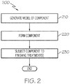
- FIG. 2 is a flowchart illustrating a method 200 for manufacturing an article/component, for example the gas turbine engine blade 100, using additive manufacturing techniques based on low energy density energy beams.
- a model such as a design model, of the component may be defined in any suitable manner.
- the model may be designed with computer aided design (CAD) software and may include three-dimensional ("3D") numeric coordinates of the entire configuration of the component including both external and internal surfaces.
- CAD computer aided design
- the model may include a number of successive two-dimensional ("2D") cross-sectional slices that together form the 3D component.
- 2D two-dimensional
- the component is formed according to the model of step 210.
- a portion of the component is formed using a rapid prototyping or additive layer manufacturing process.
- the entire component is formed using a rapid prototyping or additive layer manufacturing process.
- portions of the component may be forged or cast in step 220.
- additive layer manufacturing processes include: selective laser sintering in which a laser is used to sinter a powder media in precisely controlled locations; laser wire deposition in which a wire feedstock is melted by a laser and then deposited and solidified in precise locations to build the product; electron beam melting; laser engineered net shaping; and direct metal deposition.
- additive manufacturing techniques provide flexibility in free-form fabrication without geometric constraints, fast material processing time, and innovative joining techniques.
- direct metal laser fusion is used to produce the article/component in step 220, such as blade 100.
- DMLF is a commercially available laser-based rapid prototyping and tooling process by which complex parts may be directly produced by precision melting and solidification of metal powder into successive layers of larger structures, each layer corresponding to a cross-sectional layer of the 3D component.
- step 220 is performed with DMLF techniques to form the component.
- FIG. 3 is a schematic view of a DMLF system 300 for manufacturing the component, for example one or more gas turbine engine components, in accordance with an exemplary embodiment.
- the system 300 includes a fabrication device 310, a powder delivery device 330, a scanner 342, and a low energy density energy beam generator, such as a laser 360 (or an electron beam generator) that functions to manufacture the article 350 (e.g., the component) with build material 370.
- the fabrication device 310 includes a build container 312 with a fabrication support 314 on which the article 350 is formed and supported.
- the fabrication support 314 is movable within the build container 312 in a vertical direction and is adjusted in such a way to define a working plane 316.
- the delivery device 330 includes a powder chamber 332 with a delivery support 334 that supports the build material 370 and is also movable in the vertical direction.
- the delivery device 330 further includes a roller or wiper 336 that transfers build material 370 from the delivery device 330 to the fabrication device 310.
- a build plate 340 may be installed on the fabrication support 314.
- the fabrication support 314 is lowered and the delivery support 334 is raised.
- the roller or wiper 336 scrapes or otherwise pushes a portion of the build material 370 from the delivery device 330 to form the working plane 316 in the fabrication device 310.
- the laser 360 emits a laser beam 362, which is directed by the scanner 342 onto the build material 370 in the working plane 316 to selectively fuse the build material 370 into a cross-sectional layer of the article 350 according to the design.
- the speed, position, and other operating parameters of the laser beam 362 are controlled to selectively fuse the powder of the build material 370 into larger structures by rapidly melting the powder particles that may melt or diffuse into the solid structure below, and subsequently, cool and re-solidify.
- each layer of build material 370 may include unfused and fused build material 370 that respectively corresponds to the cross-sectional passages and walls that form the article 350.
- the laser beam 362 is relatively low power to selectively fuse the individual layer of build material 370.
- the laser beam 362 may have a power of approximately 50 to 500 Watts, although any suitable power may be provided.
- the article 350 is fabricated with the build direction as the vertical / longitudinal direction for the direction of desired elongated grains.
- the blade 100 would thus be additively-manufactured starting from the bottom of the attachment section 102, proceeding, layer-by-layer, up to the platform 106, and thereafter proceeding to the airfoil 104, and finishing with the tip outer wall 122.
- the person having ordinary skill in the art will be well-aware of the desired direction of elongated grains (which may be dependent on the intended use of the article), and will utilize an appropriately-oriented CAD schematic to achieve the layer-by-layer additive manufacturing of the desired article accordingly.
- a directionally solidified or single crystal seed starter may be fastened to the build plate 340 to promote directionally solidified grains in the desired vertical / longitudinal direction.
- a seed crystal is provided having at least a predetermined primary orientation.
- seed crystals employed for producing a directionally solidified and single crystal microstructures may have at least the predetermined primary orientation. Scanning the pattern to melt the deposited powder allows the deposited metal powder to acquire the crystallographic orientation of the seed crystal.
- the initial layer comprises a plurality of grains that are arranged in crystal structures having the predetermined primary orientation.
- the desired primary orientation is obtained by positioning the seed crystal in the predetermined primary orientation.
- the predetermined primary orientation is ⁇ 001>.
- the successive layer comprises a plurality of grains that are arranged in crystal structures having at least the predetermined primary orientation. Further information regarding the use of seed crystals may be found in commonly-assigned U.S. Patent 8,728,388 .
- the build plate 340 may be heated during the build process in order to support continued growth in the primary orientation.
- the fabrication support 314 Upon completion of a respective layer, the fabrication support 314 is lowered and the delivery support 334 is raised. Typically, the fabrication support 314, and thus the article 350, does not move in a horizontal plane during this step.
- the roller or wiper 336 again pushes a portion of the build material 370 from the delivery device 330 to form an additional layer of build material 370 on the working plane 316 of the fabrication device 310.
- the laser beam 362 is movably supported relative to the article 350 and is again controlled to selectively form another cross-sectional layer.
- the article 350 is positioned in a bed of build material 370 as the successive layers are formed such that the unfused and fused material supports subsequent layers. This process is continued according to the modeled design as successive cross-sectional layers are formed into the completed desired portion, e.g., the component of step 220.
- the delivery of build material 370 and movement of the article 350 in the vertical direction are relatively constant and only the movement of the laser beam 362 is selectively controlled to provide a simpler and more precise implementation.
- the localized fusing of the build material 370 enables more precise placement of fused material to reduce or eliminate the occurrence of over-deposition of material and excessive energy or heat, which may otherwise result in cracking or distortion.
- the unused and unfused build material 370 may be reused, thereby further reducing scrap.
- the build material 370 may be provided as a metallic superalloy.
- nickel-based superalloys are commonly used.
- a suitable nickel-based superalloy for use with the methods of the present disclosure is the alloy Mar-M-247, the elemental constituents of which are well-known in the art.
- the article/component may be given a stress relief treatment and then is removed from the additive manufacturing system (e.g., from the DMLF system 300).
- the component formed in step 220 may undergo finishing treatments. Finishing treatments may include, for example, polishing and/or the application of coatings. If necessary, the component may be machined to final specifications.
- gas turbine engine components can be manufactured by the DMLF process (optionally including machining) described herein.
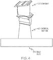
- a sacrificial gradient heat sink portion 401 is fabricated outside the article, e.g., blade 100, and metallurgically coupled with the article 100, starting from the build plate 340, as shown in FIG. 4 .
- the sacrificial gradient heat sink may be provided to ensure a thermal gradient is present in the component during subsequent heat treatment, as will be described in greater detail below.
- the sacrificial gradient heat sink portion may be fabricated on the opposite side of the component 100 away from the build plate 340.
- the sacrificial gradient heat sink portion 401 may be provided to extract heat out of the component during subsequent heat treatment, thus maintaining the thermal gradient necessary to directionally recrystallize the microstructure in the preferential (longitudinal) direction.
- the present disclosure utilizes an innovative gradient anneal heat treatment to produce a directionally recrystallized microstructure in additively-manufactured articles to give an added directional force for secondary recrystallization in a preferred direction.
- Un-treated additively-manufactured articles consist of epitaxially-grown fine grains at each section, generally perpendicular to the build direction.
- an added thermal force is applied for further grain growth to occur in the build direction.
- the present disclosure utilizes the elongated grain growth from the additive manufacturing process to obtain a directionally recrystallized microstructure for improved mechanical properties such as creep or stress rupture strength.
- Combining an additively-manufactured elongated grain microstructure in conjunction with an innovative gradient heat treatment method produces a directionally recrystallized microstructure that provides superior mechanical properties over using additively-manufactured parts without a gradient heat treatment.
- the article e.g., blade 100
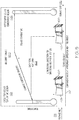
- the gradient furnace generally includes a furnace inlet 511 and a furnace outlet 512, and a conveyor belt 501 that between the inlet 511 and the outlet 512.
- Regions of the interior of furnace 500 nearer the furnace inlet 511 may be referred to as a cooler temperature region 521, whereas regions of the interior of furnace 500 nearer the furnace outlet 512 may be referred to as a hotter temperature region 522.
- the cooler temperature region 521 operates at a temperature below the gamma prime solvus temperature of the metal material (e.g., nickel-based superalloy) that forms the article, whereas the hotter temperature region 522 operates at a temperature above the gamma prime solvus temperature of the metal material.
- a temperature gradient exists between the regions 521 and 522, as illustrated in FIG. 5 .
- the component is processed through the gradient furnace 500 such that the sacrificial heat sink 401 (if provided) is the last portion of the component to be heated by the furnace 500.
- the sacrificial heat sink 401 (while still in the furnace cool zone) draws heat from the article which is in the hotter zones of the furnace (522), thus providing a temperature gradient in the additively-manufactured article, which then results in a directionally recrystallized microstructure.
- the article is processed through the gradient furnace 500 with the temperature of the article continuing to ramp until it is above its gamma prime solvus temperature. In some embodiments, as illustrated, the article temperature ramps up past the gamma prime solvus temperature while the sacrificial heat sink 401 (if provided) is still in the lower temperature sub-solvus temperature zone of the furnace 500.
- the article is processed at a translational rate through the furnace 500 until the entire article traverses through the high temperature super-solvus temperature zone 522 to achieve directionally recrystallized grain growth in the longitudinal (oven-traverse) direction.
- the step of conveying the metallic article through the gradient furnace 500 is performed at a conveyance rate of about 1 to about 2 inches per hour, such as about 1.5 inches per hour.
- the actual rate employed is dependent on the size, shape, and configuration of the article, as well as the material employed, and may require as small amount of experimentation by the operator to determine an optimal rate for the article at issue.
- the article Upon exiting the gradient furnace 500, the article has a directionally-recrystallized microstructure, as alluded to above. Subsequent to exiting the gradient furnace 500, further processing steps may optionally be employed. These further processing steps include, for example, quenching in a non-oil quenching medium, removing the sacrificial heat sink portion 401 from the article, ageing to optimize the mechanical properties of the article, inspections to confirm acceptable metallography, machining to the final, desired shape of the article, and encapsulation, such as encapsulation according to the process disclosed in commonly-assigned U.S. Patent Application Publication 2011/0311389 .
- the present disclosure has provided methods for directionally-recrystallizing metallic articles, such as gas turbine engine blades and vanes, which are manufactured using additive manufacturing techniques, such as direct metal laser sintering or electron beam melting.
- additive manufacturing techniques such as direct metal laser sintering or electron beam melting.
Landscapes
- Engineering & Computer Science (AREA)
- Manufacturing & Machinery (AREA)
- Chemical & Material Sciences (AREA)
- Materials Engineering (AREA)
- Mechanical Engineering (AREA)
- Physics & Mathematics (AREA)
- Thermal Sciences (AREA)
- Crystallography & Structural Chemistry (AREA)
- Metallurgy (AREA)
- Organic Chemistry (AREA)
- General Engineering & Computer Science (AREA)
- Automation & Control Theory (AREA)
- Architecture (AREA)
- Powder Metallurgy (AREA)
Claims (10)
- Verfahren zur Herstellung eines metallischen Artikels, umfassend die folgenden Schritte:Bereitstellen eines metallischen Materials in Pulverform;schichtweises Aufbauen des metallischen Artikels unter Verwendung eines generativen Fertigungsprozesses aus dem pulverförmigen metallischen Material in einer Aufbaurichtung, wobei als Ergebnis des generativen Fertigungsprozesses der metallische Artikel säulenförmige Kornstrukturen umfasst, die in der Aufbaurichtung ausgerichtet sind;Aufbauen eines Opferstücks auf den metallischen Artikel unter Verwendung des generativen Fertigungsprozesses, wobei das Opferstück mit dem metallischen Artikel metallurgisch gekoppelt wird und das metallische Material umfasst; undBefördern des metallischen Artikels durch einen Gradientenofen in einer Förderrichtung von einem ersten Bereich des Gradientenofens zu einem zweiten Bereich des Gradientenofens, um eine Größe der säulenförmigen Kornstrukturen im metallischen Artikel zu vergrößern, wobei der metallische Artikel in einer derartigen Ausrichtung durch den Gradientenofen befördert wird, dass die in der Aufbaurichtung ausgerichteten säulenförmigen Strukturen im Wesentlichen parallel zur Förderrichtung sind, wobei der erste Bereich des Gradientenofens den metallischen Artikel auf eine Temperatur erhitzt, die unter einer Solvustemperatur des metallischen Materials ist, und der zweiten Bereich des Gradientenofens den metallischen Artikel auf eine Temperatur erhitzt, die über der Solvustemperatur des metallischen Materials ist, wobei die Temperatur des Gradientenofens vom ersten Bereich zum zweiten Bereich stufenweise zunimmt, und wobei der metallische Artikel in Bezug auf den Gradientenofen derart ausgerichtet wird, dass das Opferstück nach dem metallischen Artikel, auf den das Opferstück aufgebaut ist, in den Gradientenofen eintritt.
- Verfahren nach Anspruch 1, wobei es sich bei dem generativen Fertigungsprozess entweder um Elektronenstrahlschmelzen (EBM) oder direktes Metall-Laserschmelzen (DMLF) handelt.
- Verfahren nach Anspruch 1, ferner umfassend ein Entfernen des Opferstücks vom metallischen Artikel nach dem Schritt des Beförderns des metallischen Artikels durch den Gradientenofen.
- Verfahren nach Anspruch 1, wobei der generative Fertigungsprozess eine beheizte Aufbauplatte einsetzt, um den metallischen Artikel während seines schichtweisen Aufbaus in der Aufbaurichtung auf einer erhöhten Temperatur zu halten.
- Verfahren nach Anspruch 1, wobei der generative Fertigungsprozess eine gerichtet kristallisierte metallische Keimschicht einsetzt und den metallischen Artikel schichtweise ab der Keimschicht aufbaut, um dadurch zu einer verbesserten säulenförmigen Kornstruktur des metallischen Artikels zu führen, die in der Aufbaurichtung ausgerichtet ist.
- Verfahren nach Anspruch 1, wobei das metallische Material eine Superlegierung auf Ni-Basis umfasst.
- Verfahren nach Anspruch 1, wobei der metallische Artikel eine Gasturbinenmotorkomponente, wie beispielsweise ein Turbinenblatt, eine Schaufel oder eine Düse, umfasst.
- Verfahren nach Anspruch 1, ferner umfassend ein Abschrecken des metallischen Artikels in einem nichtöligen Abschreckmedium nach dem Befördern des metallischen Artikels durch den Gradientenofen.
- Verfahren nach Anspruch 8, ferner umfassend ein Durchführen eines oder mehrerer von heißisostatischem Pressen, Altern und Bearbeiten des metallischen Artikels nach dem Abschrecken des metallischen Artikels.
- Verfahren nach Anspruch 1, wobei der Schritt des Beförderns des metallischen Artikels durch den Gradentenofen bei einer Fördergeschwindigkeit von etwa 1 bis etwa 2 Zoll pro Stunde ausgeführt wird.
Applications Claiming Priority (1)
| Application Number | Priority Date | Filing Date | Title |
|---|---|---|---|
| US15/250,057 US10252337B2 (en) | 2016-08-29 | 2016-08-29 | Methods for directionally recrystallizing additively-manufactured metallic articles by heat treatment with a gradient furnace |
Publications (2)
| Publication Number | Publication Date |
|---|---|
| EP3290135A1 EP3290135A1 (de) | 2018-03-07 |
| EP3290135B1 true EP3290135B1 (de) | 2019-06-26 |
Family
ID=59699475
Family Applications (1)
| Application Number | Title | Priority Date | Filing Date |
|---|---|---|---|
| EP17185425.0A Active EP3290135B1 (de) | 2016-08-29 | 2017-08-08 | Verfahren zur gerichteten rekristallisation von generativ gefertigten metallischen artikeln durch wärmebehandlung mit einem gradientenofen |
Country Status (2)
| Country | Link |
|---|---|
| US (1) | US10252337B2 (de) |
| EP (1) | EP3290135B1 (de) |
Families Citing this family (11)
| Publication number | Priority date | Publication date | Assignee | Title |
|---|---|---|---|---|
| US10814445B2 (en) * | 2016-05-09 | 2020-10-27 | Raytheon Technologies Corporation | Airfoil machining |
| EP3323531A1 (de) * | 2016-11-18 | 2018-05-23 | Ansaldo Energia IP UK Limited | Verfahren zur herstellung einer mechanischen komponente |
| DE102018207248A1 (de) * | 2018-05-09 | 2019-11-14 | Siemens Aktiengesellschaft | Verfahren zur additiven Herstellung eines Bauteils mit oxidischer Dispersionsverstärkung und entsprechendes Bauteil |
| US11426818B2 (en) | 2018-08-10 | 2022-08-30 | The Research Foundation for the State University | Additive manufacturing processes and additively manufactured products |
| EP3627253A1 (de) * | 2018-09-18 | 2020-03-25 | Siemens Aktiengesellschaft | Datenstrukturprodukt und produktkit |
| DE102019207553A1 (de) * | 2019-05-23 | 2020-11-26 | Siemens Aktiengesellschaft | Herstellungsverfahren mit additivem Herstellen eines Formkörpers, Herstellung einer Form und Wärmebehandlung |
| US11925985B2 (en) * | 2019-06-26 | 2024-03-12 | Hamilton Sundstrand Corporation | Method of making a radial turbine wheel using additive manufacturing |
| GB202007591D0 (en) * | 2020-05-21 | 2020-07-08 | Renishaw Plc | Additive manufacturing methods and apparatus for forming objects from a nickel-based supperally in a layer-by-layer manner |
| WO2022214630A1 (en) * | 2021-04-10 | 2022-10-13 | Dadbakhsh Sasan | System and method for forming single crystal components using additive manufacturing tooling |
| US20250162036A1 (en) * | 2022-02-19 | 2025-05-22 | Massachusetts Institute Of Technology | Directional recrystallization processing of additively manufactured metal alloys |
| US11905975B1 (en) * | 2022-08-10 | 2024-02-20 | Hamilton Sundstrand Corporation | Radial compressor with leading edge air injection |
Family Cites Families (8)
| Publication number | Priority date | Publication date | Assignee | Title |
|---|---|---|---|---|
| US3975219A (en) | 1975-09-02 | 1976-08-17 | United Technologies Corporation | Thermomechanical treatment for nickel base superalloys |
| CA1136905A (en) | 1978-06-06 | 1982-12-07 | Romeo G. Bourdeau | Superalloy composition and process |
| US4226644A (en) | 1978-09-05 | 1980-10-07 | United Technologies Corporation | High gamma prime superalloys by powder metallurgy |
| US4318753A (en) | 1979-10-12 | 1982-03-09 | United Technologies Corporation | Thermal treatment and resultant microstructures for directional recrystallized superalloys |
| EP1595968A1 (de) | 2004-04-30 | 2005-11-16 | Siemens Aktiengesellschaft | Wärmebehandlungsverfahren für einkristalline oder direktional verfestigte Bauteile |
| US8728388B2 (en) | 2009-12-04 | 2014-05-20 | Honeywell International Inc. | Method of fabricating turbine components for engines |
| US9175568B2 (en) | 2010-06-22 | 2015-11-03 | Honeywell International Inc. | Methods for manufacturing turbine components |
| EP2900964A4 (de) | 2012-09-28 | 2016-06-29 | United Technologies Corp | Durch additive fertigung hergestellte übergekühlte turbinenabschnittskomponente |
-
2016
- 2016-08-29 US US15/250,057 patent/US10252337B2/en not_active Expired - Fee Related
-
2017
- 2017-08-08 EP EP17185425.0A patent/EP3290135B1/de active Active
Non-Patent Citations (1)
| Title |
|---|
| None * |
Also Published As
| Publication number | Publication date |
|---|---|
| US20180056396A1 (en) | 2018-03-01 |
| EP3290135A1 (de) | 2018-03-07 |
| US10252337B2 (en) | 2019-04-09 |
Similar Documents
| Publication | Publication Date | Title |
|---|---|---|
| EP3290135B1 (de) | Verfahren zur gerichteten rekristallisation von generativ gefertigten metallischen artikeln durch wärmebehandlung mit einem gradientenofen | |
| US9266170B2 (en) | Multi-material turbine components | |
| EP2754515B1 (de) | Verfahren zur herstellung von gasturbinenmotorkomponenten mittels additiver herstellungsverfahren. | |
| US8691333B2 (en) | Methods for manufacturing engine components with structural bridge devices | |
| EP2942424B1 (de) | Verfahren zur herstellung eines gerichtet erstarrten ersatzkörpers für eine komponente mit zusatzstoffherstellung | |
| EP2708296B1 (de) | Verfahren zur Herstellung Turbinenstatorschaufelanordnungen mit generativer Herstellungsmethode | |
| EP2947184B1 (de) | Verfahren zur formung von komponenten mittels additivherstellung und abschmelzen | |
| US9393620B2 (en) | Uber-cooled turbine section component made by additive manufacturing | |
| CN104662274B (zh) | 通过增材制造技术制备的超级冷却的涡轮区段组件 | |
| US20170284206A1 (en) | High porosity material and method of making thereof | |
| EP3241634B1 (de) | Verfahren zur herstellung einer komponente mit einer gerichtet verfestigten mikrostruktur oder einer einkristallinen mikrostruktur | |
| US10780528B2 (en) | Methods for residual stress reduction in additive manufacturing processes | |
| US9718127B2 (en) | Method for forming components using additive manufacturing and re-melt | |
| US11421541B2 (en) | Turbine nozzle with compliant joint |
Legal Events
| Date | Code | Title | Description |
|---|---|---|---|
| PUAI | Public reference made under article 153(3) epc to a published international application that has entered the european phase |
Free format text: ORIGINAL CODE: 0009012 |
|
| STAA | Information on the status of an ep patent application or granted ep patent |
Free format text: STATUS: REQUEST FOR EXAMINATION WAS MADE |
|
| 17P | Request for examination filed |
Effective date: 20170808 |
|
| AK | Designated contracting states |
Kind code of ref document: A1 Designated state(s): AL AT BE BG CH CY CZ DE DK EE ES FI FR GB GR HR HU IE IS IT LI LT LU LV MC MK MT NL NO PL PT RO RS SE SI SK SM TR |
|
| AX | Request for extension of the european patent |
Extension state: BA ME |
|
| RIC1 | Information provided on ipc code assigned before grant |
Ipc: B33Y 10/00 20150101ALI20181214BHEP Ipc: B22F 3/24 20060101ALI20181214BHEP Ipc: C22F 1/10 20060101ALI20181214BHEP Ipc: B22F 5/04 20060101ALI20181214BHEP Ipc: B22F 3/105 20060101AFI20181214BHEP Ipc: B22F 5/00 20060101ALI20181214BHEP Ipc: B33Y 40/00 20150101ALI20181214BHEP Ipc: B33Y 80/00 20150101ALI20181214BHEP |
|
| GRAP | Despatch of communication of intention to grant a patent |
Free format text: ORIGINAL CODE: EPIDOSNIGR1 |
|
| STAA | Information on the status of an ep patent application or granted ep patent |
Free format text: STATUS: GRANT OF PATENT IS INTENDED |
|
| INTG | Intention to grant announced |
Effective date: 20190125 |
|
| GRAS | Grant fee paid |
Free format text: ORIGINAL CODE: EPIDOSNIGR3 |
|
| GRAA | (expected) grant |
Free format text: ORIGINAL CODE: 0009210 |
|
| STAA | Information on the status of an ep patent application or granted ep patent |
Free format text: STATUS: THE PATENT HAS BEEN GRANTED |
|
| AK | Designated contracting states |
Kind code of ref document: B1 Designated state(s): AL AT BE BG CH CY CZ DE DK EE ES FI FR GB GR HR HU IE IS IT LI LT LU LV MC MK MT NL NO PL PT RO RS SE SI SK SM TR |
|
| REG | Reference to a national code |
Ref country code: GB Ref legal event code: FG4D |
|
| REG | Reference to a national code |
Ref country code: CH Ref legal event code: EP |
|
| REG | Reference to a national code |
Ref country code: AT Ref legal event code: REF Ref document number: 1147724 Country of ref document: AT Kind code of ref document: T Effective date: 20190715 |
|
| REG | Reference to a national code |
Ref country code: IE Ref legal event code: FG4D |
|
| REG | Reference to a national code |
Ref country code: DE Ref legal event code: R096 Ref document number: 602017004805 Country of ref document: DE |
|
| REG | Reference to a national code |
Ref country code: NL Ref legal event code: MP Effective date: 20190626 |
|
| PG25 | Lapsed in a contracting state [announced via postgrant information from national office to epo] |
Ref country code: SE Free format text: LAPSE BECAUSE OF FAILURE TO SUBMIT A TRANSLATION OF THE DESCRIPTION OR TO PAY THE FEE WITHIN THE PRESCRIBED TIME-LIMIT Effective date: 20190626 Ref country code: HR Free format text: LAPSE BECAUSE OF FAILURE TO SUBMIT A TRANSLATION OF THE DESCRIPTION OR TO PAY THE FEE WITHIN THE PRESCRIBED TIME-LIMIT Effective date: 20190626 Ref country code: AL Free format text: LAPSE BECAUSE OF FAILURE TO SUBMIT A TRANSLATION OF THE DESCRIPTION OR TO PAY THE FEE WITHIN THE PRESCRIBED TIME-LIMIT Effective date: 20190626 Ref country code: FI Free format text: LAPSE BECAUSE OF FAILURE TO SUBMIT A TRANSLATION OF THE DESCRIPTION OR TO PAY THE FEE WITHIN THE PRESCRIBED TIME-LIMIT Effective date: 20190626 Ref country code: NO Free format text: LAPSE BECAUSE OF FAILURE TO SUBMIT A TRANSLATION OF THE DESCRIPTION OR TO PAY THE FEE WITHIN THE PRESCRIBED TIME-LIMIT Effective date: 20190926 Ref country code: LT Free format text: LAPSE BECAUSE OF FAILURE TO SUBMIT A TRANSLATION OF THE DESCRIPTION OR TO PAY THE FEE WITHIN THE PRESCRIBED TIME-LIMIT Effective date: 20190626 |
|
| REG | Reference to a national code |
Ref country code: LT Ref legal event code: MG4D |
|
| PG25 | Lapsed in a contracting state [announced via postgrant information from national office to epo] |
Ref country code: BG Free format text: LAPSE BECAUSE OF FAILURE TO SUBMIT A TRANSLATION OF THE DESCRIPTION OR TO PAY THE FEE WITHIN THE PRESCRIBED TIME-LIMIT Effective date: 20190926 Ref country code: RS Free format text: LAPSE BECAUSE OF FAILURE TO SUBMIT A TRANSLATION OF THE DESCRIPTION OR TO PAY THE FEE WITHIN THE PRESCRIBED TIME-LIMIT Effective date: 20190626 Ref country code: LV Free format text: LAPSE BECAUSE OF FAILURE TO SUBMIT A TRANSLATION OF THE DESCRIPTION OR TO PAY THE FEE WITHIN THE PRESCRIBED TIME-LIMIT Effective date: 20190626 Ref country code: GR Free format text: LAPSE BECAUSE OF FAILURE TO SUBMIT A TRANSLATION OF THE DESCRIPTION OR TO PAY THE FEE WITHIN THE PRESCRIBED TIME-LIMIT Effective date: 20190927 |
|
| REG | Reference to a national code |
Ref country code: AT Ref legal event code: MK05 Ref document number: 1147724 Country of ref document: AT Kind code of ref document: T Effective date: 20190626 |
|
| PG25 | Lapsed in a contracting state [announced via postgrant information from national office to epo] |
Ref country code: NL Free format text: LAPSE BECAUSE OF FAILURE TO SUBMIT A TRANSLATION OF THE DESCRIPTION OR TO PAY THE FEE WITHIN THE PRESCRIBED TIME-LIMIT Effective date: 20190626 Ref country code: AT Free format text: LAPSE BECAUSE OF FAILURE TO SUBMIT A TRANSLATION OF THE DESCRIPTION OR TO PAY THE FEE WITHIN THE PRESCRIBED TIME-LIMIT Effective date: 20190626 Ref country code: EE Free format text: LAPSE BECAUSE OF FAILURE TO SUBMIT A TRANSLATION OF THE DESCRIPTION OR TO PAY THE FEE WITHIN THE PRESCRIBED TIME-LIMIT Effective date: 20190626 Ref country code: RO Free format text: LAPSE BECAUSE OF FAILURE TO SUBMIT A TRANSLATION OF THE DESCRIPTION OR TO PAY THE FEE WITHIN THE PRESCRIBED TIME-LIMIT Effective date: 20190626 Ref country code: SK Free format text: LAPSE BECAUSE OF FAILURE TO SUBMIT A TRANSLATION OF THE DESCRIPTION OR TO PAY THE FEE WITHIN THE PRESCRIBED TIME-LIMIT Effective date: 20190626 Ref country code: CZ Free format text: LAPSE BECAUSE OF FAILURE TO SUBMIT A TRANSLATION OF THE DESCRIPTION OR TO PAY THE FEE WITHIN THE PRESCRIBED TIME-LIMIT Effective date: 20190626 Ref country code: PT Free format text: LAPSE BECAUSE OF FAILURE TO SUBMIT A TRANSLATION OF THE DESCRIPTION OR TO PAY THE FEE WITHIN THE PRESCRIBED TIME-LIMIT Effective date: 20191028 |
|
| PG25 | Lapsed in a contracting state [announced via postgrant information from national office to epo] |
Ref country code: IS Free format text: LAPSE BECAUSE OF FAILURE TO SUBMIT A TRANSLATION OF THE DESCRIPTION OR TO PAY THE FEE WITHIN THE PRESCRIBED TIME-LIMIT Effective date: 20191026 Ref country code: SM Free format text: LAPSE BECAUSE OF FAILURE TO SUBMIT A TRANSLATION OF THE DESCRIPTION OR TO PAY THE FEE WITHIN THE PRESCRIBED TIME-LIMIT Effective date: 20190626 Ref country code: IT Free format text: LAPSE BECAUSE OF FAILURE TO SUBMIT A TRANSLATION OF THE DESCRIPTION OR TO PAY THE FEE WITHIN THE PRESCRIBED TIME-LIMIT Effective date: 20190626 Ref country code: ES Free format text: LAPSE BECAUSE OF FAILURE TO SUBMIT A TRANSLATION OF THE DESCRIPTION OR TO PAY THE FEE WITHIN THE PRESCRIBED TIME-LIMIT Effective date: 20190626 |
|
| PG25 | Lapsed in a contracting state [announced via postgrant information from national office to epo] |
Ref country code: TR Free format text: LAPSE BECAUSE OF FAILURE TO SUBMIT A TRANSLATION OF THE DESCRIPTION OR TO PAY THE FEE WITHIN THE PRESCRIBED TIME-LIMIT Effective date: 20190626 |
|
| PG25 | Lapsed in a contracting state [announced via postgrant information from national office to epo] |
Ref country code: DK Free format text: LAPSE BECAUSE OF FAILURE TO SUBMIT A TRANSLATION OF THE DESCRIPTION OR TO PAY THE FEE WITHIN THE PRESCRIBED TIME-LIMIT Effective date: 20190626 Ref country code: PL Free format text: LAPSE BECAUSE OF FAILURE TO SUBMIT A TRANSLATION OF THE DESCRIPTION OR TO PAY THE FEE WITHIN THE PRESCRIBED TIME-LIMIT Effective date: 20190626 |
|
| PG25 | Lapsed in a contracting state [announced via postgrant information from national office to epo] |
Ref country code: IS Free format text: LAPSE BECAUSE OF FAILURE TO SUBMIT A TRANSLATION OF THE DESCRIPTION OR TO PAY THE FEE WITHIN THE PRESCRIBED TIME-LIMIT Effective date: 20200320 Ref country code: MC Free format text: LAPSE BECAUSE OF FAILURE TO SUBMIT A TRANSLATION OF THE DESCRIPTION OR TO PAY THE FEE WITHIN THE PRESCRIBED TIME-LIMIT Effective date: 20190626 Ref country code: LU Free format text: LAPSE BECAUSE OF NON-PAYMENT OF DUE FEES Effective date: 20190808 |
|
| REG | Reference to a national code |
Ref country code: BE Ref legal event code: MM Effective date: 20190831 |
|
| REG | Reference to a national code |
Ref country code: DE Ref legal event code: R097 Ref document number: 602017004805 Country of ref document: DE |
|
| PLBE | No opposition filed within time limit |
Free format text: ORIGINAL CODE: 0009261 |
|
| STAA | Information on the status of an ep patent application or granted ep patent |
Free format text: STATUS: NO OPPOSITION FILED WITHIN TIME LIMIT |
|
| PG2D | Information on lapse in contracting state deleted |
Ref country code: IS |
|
| PG25 | Lapsed in a contracting state [announced via postgrant information from national office to epo] |
Ref country code: FR Free format text: LAPSE BECAUSE OF NON-PAYMENT OF DUE FEES Effective date: 20190826 Ref country code: IE Free format text: LAPSE BECAUSE OF NON-PAYMENT OF DUE FEES Effective date: 20190808 |
|
| 26N | No opposition filed |
Effective date: 20200603 |
|
| PG25 | Lapsed in a contracting state [announced via postgrant information from national office to epo] |
Ref country code: BE Free format text: LAPSE BECAUSE OF NON-PAYMENT OF DUE FEES Effective date: 20190831 Ref country code: SI Free format text: LAPSE BECAUSE OF FAILURE TO SUBMIT A TRANSLATION OF THE DESCRIPTION OR TO PAY THE FEE WITHIN THE PRESCRIBED TIME-LIMIT Effective date: 20190626 |
|
| REG | Reference to a national code |
Ref country code: CH Ref legal event code: PL |
|
| PG25 | Lapsed in a contracting state [announced via postgrant information from national office to epo] |
Ref country code: CH Free format text: LAPSE BECAUSE OF NON-PAYMENT OF DUE FEES Effective date: 20200831 Ref country code: LI Free format text: LAPSE BECAUSE OF NON-PAYMENT OF DUE FEES Effective date: 20200831 |
|
| PG25 | Lapsed in a contracting state [announced via postgrant information from national office to epo] |
Ref country code: CY Free format text: LAPSE BECAUSE OF FAILURE TO SUBMIT A TRANSLATION OF THE DESCRIPTION OR TO PAY THE FEE WITHIN THE PRESCRIBED TIME-LIMIT Effective date: 20190626 |
|
| PG25 | Lapsed in a contracting state [announced via postgrant information from national office to epo] |
Ref country code: HU Free format text: LAPSE BECAUSE OF FAILURE TO SUBMIT A TRANSLATION OF THE DESCRIPTION OR TO PAY THE FEE WITHIN THE PRESCRIBED TIME-LIMIT; INVALID AB INITIO Effective date: 20170808 Ref country code: MT Free format text: LAPSE BECAUSE OF FAILURE TO SUBMIT A TRANSLATION OF THE DESCRIPTION OR TO PAY THE FEE WITHIN THE PRESCRIBED TIME-LIMIT Effective date: 20190626 |
|
| GBPC | Gb: european patent ceased through non-payment of renewal fee |
Effective date: 20210808 |
|
| PG25 | Lapsed in a contracting state [announced via postgrant information from national office to epo] |
Ref country code: MK Free format text: LAPSE BECAUSE OF FAILURE TO SUBMIT A TRANSLATION OF THE DESCRIPTION OR TO PAY THE FEE WITHIN THE PRESCRIBED TIME-LIMIT Effective date: 20190626 |
|
| PG25 | Lapsed in a contracting state [announced via postgrant information from national office to epo] |
Ref country code: GB Free format text: LAPSE BECAUSE OF NON-PAYMENT OF DUE FEES Effective date: 20210808 |
|
| P01 | Opt-out of the competence of the unified patent court (upc) registered |
Effective date: 20230525 |
|
| PGFP | Annual fee paid to national office [announced via postgrant information from national office to epo] |
Ref country code: DE Payment date: 20250827 Year of fee payment: 9 |