EP3290182A1 - Rohrherstellungsvorrichtung und rohrherstellungsverfahren für spiralrohr - Google Patents
Rohrherstellungsvorrichtung und rohrherstellungsverfahren für spiralrohr Download PDFInfo
- Publication number
- EP3290182A1 EP3290182A1 EP16786519.5A EP16786519A EP3290182A1 EP 3290182 A1 EP3290182 A1 EP 3290182A1 EP 16786519 A EP16786519 A EP 16786519A EP 3290182 A1 EP3290182 A1 EP 3290182A1
- Authority
- EP
- European Patent Office
- Prior art keywords
- pipe
- making apparatus
- resisting force
- spiral pipe
- strip
- Prior art date
- Legal status (The legal status is an assumption and is not a legal conclusion. Google has not performed a legal analysis and makes no representation as to the accuracy of the status listed.)
- Granted
Links
Images








Classifications
-
- B—PERFORMING OPERATIONS; TRANSPORTING
- B29—WORKING OF PLASTICS; WORKING OF SUBSTANCES IN A PLASTIC STATE IN GENERAL
- B29C—SHAPING OR JOINING OF PLASTICS; SHAPING OF MATERIAL IN A PLASTIC STATE, NOT OTHERWISE PROVIDED FOR; AFTER-TREATMENT OF THE SHAPED PRODUCTS, e.g. REPAIRING
- B29C63/00—Lining or sheathing, i.e. applying preformed layers or sheathings of plastics; Apparatus therefor
- B29C63/26—Lining or sheathing of internal surfaces
- B29C63/30—Lining or sheathing of internal surfaces using sheet or web-like material
- B29C63/32—Lining or sheathing of internal surfaces using sheet or web-like material by winding helically
-
- B—PERFORMING OPERATIONS; TRANSPORTING
- B29—WORKING OF PLASTICS; WORKING OF SUBSTANCES IN A PLASTIC STATE IN GENERAL
- B29C—SHAPING OR JOINING OF PLASTICS; SHAPING OF MATERIAL IN A PLASTIC STATE, NOT OTHERWISE PROVIDED FOR; AFTER-TREATMENT OF THE SHAPED PRODUCTS, e.g. REPAIRING
- B29C53/00—Shaping by bending, folding, twisting, straightening or flattening; Apparatus therefor
- B29C53/56—Winding and joining, e.g. winding spirally
- B29C53/58—Winding and joining, e.g. winding spirally helically
- B29C53/581—Winding and joining, e.g. winding spirally helically using sheets or strips consisting principally of plastics material
-
- B—PERFORMING OPERATIONS; TRANSPORTING
- B29—WORKING OF PLASTICS; WORKING OF SUBSTANCES IN A PLASTIC STATE IN GENERAL
- B29C—SHAPING OR JOINING OF PLASTICS; SHAPING OF MATERIAL IN A PLASTIC STATE, NOT OTHERWISE PROVIDED FOR; AFTER-TREATMENT OF THE SHAPED PRODUCTS, e.g. REPAIRING
- B29C53/00—Shaping by bending, folding, twisting, straightening or flattening; Apparatus therefor
- B29C53/80—Component parts, details or accessories; Auxiliary operations
- B29C53/8008—Component parts, details or accessories; Auxiliary operations specially adapted for winding and joining
-
- F—MECHANICAL ENGINEERING; LIGHTING; HEATING; WEAPONS; BLASTING
- F16—ENGINEERING ELEMENTS AND UNITS; GENERAL MEASURES FOR PRODUCING AND MAINTAINING EFFECTIVE FUNCTIONING OF MACHINES OR INSTALLATIONS; THERMAL INSULATION IN GENERAL
- F16L—PIPES; JOINTS OR FITTINGS FOR PIPES; SUPPORTS FOR PIPES, CABLES OR PROTECTIVE TUBING; MEANS FOR THERMAL INSULATION IN GENERAL
- F16L1/00—Laying or reclaiming pipes; Repairing or joining pipes on or under water
-
- F—MECHANICAL ENGINEERING; LIGHTING; HEATING; WEAPONS; BLASTING
- F16—ENGINEERING ELEMENTS AND UNITS; GENERAL MEASURES FOR PRODUCING AND MAINTAINING EFFECTIVE FUNCTIONING OF MACHINES OR INSTALLATIONS; THERMAL INSULATION IN GENERAL
- F16L—PIPES; JOINTS OR FITTINGS FOR PIPES; SUPPORTS FOR PIPES, CABLES OR PROTECTIVE TUBING; MEANS FOR THERMAL INSULATION IN GENERAL
- F16L55/00—Devices or appurtenances for use in, or in connection with, pipes or pipe systems
- F16L55/16—Devices for covering leaks in pipes or hoses, e.g. hose-menders
- F16L55/162—Devices for covering leaks in pipes or hoses, e.g. hose-menders from inside the pipe
-
- F—MECHANICAL ENGINEERING; LIGHTING; HEATING; WEAPONS; BLASTING
- F16—ENGINEERING ELEMENTS AND UNITS; GENERAL MEASURES FOR PRODUCING AND MAINTAINING EFFECTIVE FUNCTIONING OF MACHINES OR INSTALLATIONS; THERMAL INSULATION IN GENERAL
- F16L—PIPES; JOINTS OR FITTINGS FOR PIPES; SUPPORTS FOR PIPES, CABLES OR PROTECTIVE TUBING; MEANS FOR THERMAL INSULATION IN GENERAL
- F16L55/00—Devices or appurtenances for use in, or in connection with, pipes or pipe systems
- F16L55/16—Devices for covering leaks in pipes or hoses, e.g. hose-menders
- F16L55/162—Devices for covering leaks in pipes or hoses, e.g. hose-menders from inside the pipe
- F16L55/165—Devices for covering leaks in pipes or hoses, e.g. hose-menders from inside the pipe a pipe or flexible liner being inserted in the damaged section
- F16L55/1655—Devices for covering leaks in pipes or hoses, e.g. hose-menders from inside the pipe a pipe or flexible liner being inserted in the damaged section a pipe being formed inside the old pipe by winding strip-material
-
- F—MECHANICAL ENGINEERING; LIGHTING; HEATING; WEAPONS; BLASTING
- F16—ENGINEERING ELEMENTS AND UNITS; GENERAL MEASURES FOR PRODUCING AND MAINTAINING EFFECTIVE FUNCTIONING OF MACHINES OR INSTALLATIONS; THERMAL INSULATION IN GENERAL
- F16L—PIPES; JOINTS OR FITTINGS FOR PIPES; SUPPORTS FOR PIPES, CABLES OR PROTECTIVE TUBING; MEANS FOR THERMAL INSULATION IN GENERAL
- F16L55/00—Devices or appurtenances for use in, or in connection with, pipes or pipe systems
- F16L55/18—Appliances for use in repairing pipes
Definitions
- the present invention relates to a pipe-making apparatus and a pipe-making method for manufacturing a spiral pipe by spirally winding a strip member, and more particularly to a pipe-making apparatus that does not require an annular frame, a radial frame or the like for limiting a diameter of the spiral pipe and to a pipe-making method using the pipe-making apparatus.
- Patent Document 1 discloses SPR (Spiral Pipe Renewal) construction method and a pipe-making apparatus for the SPR method as an example of a rehabilitation method.
- SPR Spiral Pipe Renewal
- a pipe-making apparatus for the SPR method as an example of a rehabilitation method.
- this pipe-making apparatus while spirally winding a strip member made of a synthetic resin along an inner wall of an existing pipe, an edge of a preceding spiral pipe portion that has already been formed in a shape of a spiral pipe and an edge of a following strip portion adjacent to one another are joined by concavo-convex fitting.
- Pipe-making proceeds as the pipe-making apparatus is self-propelled in a spiral manner.
- a diameter of a spiral pipe produced by this type of pipe-making method tends to shrink as the pipe-making proceeds.
- an annular frame in which a plurality of guide rollers are annularly arranged along an inner peripheral surface of an existing pipe. The annular frame limits shrinkage of a diameter of the spiral pipe from being reduced in diameter.
- Patent Document 2 discloses a radial frame having a plurality of radially extending support arms as diameter shrinkage limiting means. A guide roller at a distal end portion of each support arm is pressed against an inner peripheral surface of a spiral pipe.
- the present invention provides a pipe-making apparatus for forming a spiral pipe by joining edges of adjacent turns of a strip member while spirally winding the strip member along a winding direction, characterized in that the apparatus including: a propulsive reaction force imparting portion disposed spaced from a joining step position at which the joining is performed, the propulsive reaction force imparting portion imparting a propulsive reaction force for moving forward in the winding direction of the strip member to a following strip portion or a preceding spiral pipe portion of the strip member, the following strip portion following the preceding spiral pipe portion precedingly made into a pipe; and a resisting force imparting portion disposed spaced from the propulsive reaction force imparting portion, the resisting force imparting portion imparting a resisting force along the winding direction to the strip member by friction with the strip member when the pipe-making apparatus is being propelled by the propulsive reaction force, a direction of the resisting force being opposite to a direction of the propulsive reaction force.
- a diameter limiting frame can be omitted and the spiral pipe having a desired diameter can be made.
- the resisting force is set at a magnitude that allows the pipe-making apparatus to be propelled and that allows the preceding spiral pipe portion to change its diameter.
- the spiral pipe can be surely made while adjusting the diameter of the spiral pipe so as to be a desired diameter.
- the resisting force of the resisting force imparting portion is adjustable in a stepped fashion or a stepless fashion.
- the diameter changing effect can be increased by increasing the resisting force.
- the diameter changing effect can be reduced by reducing the resisting force.
- the propulsive reaction force imparting portion pushes the following strip portion from in front of the joining step position in a direction of movement toward the joining step position, and wherein the resisting force imparting portion imparts the resisting force toward forward in the winding direction to the preceding spiral pipe portion.
- the propulsive reaction force imparting portion imparts the propulsive reaction force toward a returning side in the winding direction to the preceding spiral pipe portion, and wherein the resisting force imparting portion imparts the resisting force toward forward in the winding direction to a portion of the preceding spiral pipe portion spaced from the propulsive reaction force imparting portion in the winding direction.
- both of the propulsive reaction force imparting portion and the resisting force imparting portion can be disposed on the preceding spiral pipe portion.
- the diameter-expanding effect can be imparted to the preceding spiral pipe portion by disposing the resisting force imparting portion on a returning side (upstream side) in the winding direction with respect to the propulsive reaction force imparting portion.
- the diameter-shrinking effect can be imparted to the preceding spiral pipe portion by disposing the resisting force imparting portion forward (downstream side) of the propulsive reaction force imparting portion in the winding direction.
- the propulsive reaction force imparting portion and the resisting force imparting portion are disposed on the same side with each other in the direction of movement with respect to the joining step position.
- the pipe-making apparatus can be downsized. More preferably, the propulsive reaction force imparting portion and the resisting force imparting portion are disposed in front of the joining step position in the direction of movement.
- the resisting force imparting portion includes a frictionally slidable member to be frictionally slid against the strip member.
- the resisting force imparting portion includes a resistive roller, the resisting force being generated as the resistive roller is rotated.
- the resisting force can be surely imparted to the strip member.
- Magnitude of the resisting force can be adjusted by rotationally driving the resistive roller in a speed-controllable manner.
- the pipe-making apparatus further includes a retainer that is held so as to be movable with respect to the preceding spiral pipe portion in the winding direction and immovable with respect to the preceding spiral pipe portion in a width direction orthogonal to the winding direction, wherein the retainer includes a first retainer portion and a second retainer portion spaced from each other in the winding direction.
- the pipe-making apparatus can be positioned in the width direction with respect to the preceding spiral pipe portion. Moreover, the pipe-making apparatus can be prevented from being rotated even if a rotational moment is applied to the pipe-making apparatus due to an external force from the following strip portion or the like.
- the present invention provides a pipe-making method for forming a spiral pipe by joining edges of adjacent turns of a strip member while spirally winding the strip member along a winding direction, characterized in that the method including steps of: joining the edges of a following strip portion and a preceding spiral pipe portion of the strip member that are adjacent to one another, the following strip portion following the preceding spiral pipe portion that has already been made into a pipe: imparting a propulsive reaction force for moving in the winding direction of the strip member to the following strip portion or to the preceding spiral pipe portion at a position spaced from a joining step position at which the joining is performed; and imparting a resisting force along the winding direction to the strip member at a position spaced from the position for imparting the propulsive reaction force, the resisting force being imparted by friction with the strip member when the pipe-making apparatus is being propelled by the propulsive reaction force, a direction of the resisting force being opposite to a direction of the propulsive reaction force.
- a spiral pipe having a desired diameter can be made without a diameter shrinkage limiting frame such as an annular frame or a radial frame.
- a pipe-making apparatus can be downsized.
- FIG. 1 (a) shows an aged existing pipe 1 in a process of being rehabilitated.
- the existing pipe 1 may include a sewer pipe, a water supply pipe, an agricultural water pipe, a gas pipe, or the like.
- a rehabilitation pipe 9 (spiral pipe) is lined on an inner wall of the existing pipe 1.
- the rehabilitation pipe 9 is provided over an entire length of the existing pipe 1 from a start manhole 4 to an arrival manhole 4B.
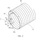
- the rehabilitation pipe 9 is made of a single elongated strip member 90 into a form of a spiral pipe.
- the strip member 90 is spirally wound and edges of adjacent turns of the strip member 90 are joined.
- the material of the strip member 90 may be a synthetic resin such as polyvinyl chloride, for example.
- the strip member 90 in a process of pipe-making includes a preceding spiral pipe portion 91 and a following strip portion 92.
- the preceding spiral pipe portion 91 having a spiral pipe configuration is formed by the strip member 90's being wound in a winding direction that is clockwise in FIG. 2 , for example.
- the preceding spiral pipe portion 91 is disposed along the inner wall of the existing pipe 1 from and end portion of the existing pipe 1 on the start manhole 4 side (right side in FIG. 1 (a) ).
- the following strip portion 92 that has not yet been made into a pipe continues from an end portion (portion continuing to the following strip portion) 91e of the preceding spiral pipe portion 91 on a downstream side in the winding direction.
- the following strip portion 92 is passed through an inside of the preceding spiral pipe portion 91 and an inside of the start manhole 4.
- the strip member 90 includes a flat strip body 90a, a pair of fitting portions 93, 94 and three (plural) reinforcement ribs 95.
- a front side surface of the strip body 90a is oriented to an inner peripheral side (upper side in FIG. 4(b) ) of the preceding spiral pipe portion 91, and thereby the rehabilitation pipe 9.
- Aback side surface of the strip body 90a is oriented to an outer peripheral side (under side in FIG. 4(b) ) of the preceding spiral pipe portion 91, and thereby the rehabilitation pipe 9.
- a first fitting portion 93 is formed in an edge portion of the strip body 90a on one side (left side in FIG. 4(b) ) in a width direction.
- the first fitting portion 93 is recessed from the front side surface (top surface in FIG. 4 (b) ) of the strip body 90a in a concave groove configuration.
- a second fitting portion 94 is formed in an edge portion of the strip body 90a on the other side (right side in FIG. 4 (b) ) in the width direction.
- the second fitting portion 94 is formed in a convex ridge configuration protruded from the back side surface (bottom surface in FIG. 4 (b) ) of the strip body 90a.
- the fitting portions 93, 94 of adjacent turns of the preceding spiral pipe portion 91, and thereby of the rehabilitation pipe 9 ( FIG. 1 (b) ) are joined in a concave-convex fitting.
- a sealing agent 96 is provided on the back side surface of the strip body 90a near the second fitting portion 94.
- the three reinforcement ribs 95 are formed parallel to one another in the back side surface of the strip body 90a.
- a reinforcement strip 97 made of a steel sheet or the like is embedded in the reinforcement rib 95.
- the fitting portions 93, 94 and the reinforcement ribs 95 or the like of the strip member 90 are not shown in FIG. 1 (a) and FIG. 2 .
- a pipe-making apparatus 3 is disposed in a distal end portion (left end portion in FIG. 1(a) ) of the preceding spiral pipe portion 91 in an extending direction.
- the pipe-making apparatus 3 is moved forward (self-propelled) along the winding direction (clockwise direction in FIG. 2 ) of the preceding spiral pipe portion 91.
- a width direction orthogonal to a direction of movement of the pipe-making apparatus 3 is inclined to an axis of the existing pipe 1 through an angle corresponding to a lead angle of the preceding spiral pipe portion 91.
- the strip member 90 is made into the rehabilitation pipe 9 by the pipe-making apparatus 3.
- a joining step position 20p is set in the pipe-making apparatus 3.
- the concave-convex fitting (joining) job is performed at the joining step position 20p.
- the pipe-making apparatus 3 includes a body frame 3a, a propulsive reaction force imparting portion 10, a fitting force imparting portion 20 (joining portion) and a resisting force imparting portion 30.
- the three force imparting portions 10, 20, 30 are disposed spaced from one another.
- the fitting force imparting portion 20 is disposed at the joining step position 20p and the propulsive reaction force imparting portion 10 and the resisting force imparting portion 30 are disposed spaced from the joining step position 20p.
- Relative positions of the force imparting portions 10, 20, 30 are fixed by the body frame 3a diagrammatically shown in the drawings in chain double-dashed lines.
- the propulsive reaction force imparting portion 10 is disposed spaced from the joining step position 20p. Specifically, the propulsive reaction force imparting portion 10 is located in front of the joining step position 20p (left side in FIG. 3 ) in the direction of movement of the pipe-making apparatus 3 and interior (upper side in FIG. 3 ) to the joining step position 20p in a radial direction of the preceding spiral pipe portion 91 and the existing pipe 1.
- the propulsive reaction force imparting portion 10 has a pair of propelling rollers 13, 13. An axis of the propelling roller 13 is oriented to the width direction of the pipe-making apparatus 3 (direction orthogonal to the plane of FIG. 3 ).
- the following strip portion 92 is caught between the pair of propelling rollers 13, 13 from an inner peripheral side (front side) and an outer peripheral side (back side).
- a rotational drive mechanism (not shown) such as a motor is connected to at least one of the propelling rollers 13, 13.
- the propelling roller 13 is rotationally driven about its own axis by the rotational drive mechanism so as to push the following strip portion 92 toward the joining step position 20p.
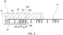
- the fitting force imparting portion 20 includes a fitting roller 23 and a fitting receiver 25.
- the fitting roller 23 is disposed on an inner peripheral side (upper side in FIG. 3 ) of the preceding spiral pipe portion 91.
- An axis of the fitting roller 23 is oriented to the width direction of the pipe-making apparatus 3 (direction orthogonal to the plane of FIG. 3 ) in parallel to the axis of the propelling roller 13.
- the fitting roller 23 is freely rotatable about its own axis. It is not required that the fitting roller 23 should be connected to a rotational drive mechanism such as a motor.
- the fitting receiver 25 has a configuration of a plate.
- the fitting receiver 25 is disposed on the outer peripheral side (under side in FIG. 3 ) of the preceding spiral pipe portion 91.
- the fitting receiver 25 is opposed to the fitting roller 23 so as to be spaced from each other in the radial direction of the preceding spiral pipe portion 91.
- the joining step position 20p is located between the fitting roller 23 and the fitting receiver 25.
- the following strip portion 92 extends diagonally outwardly with respect to the radial direction of the preceding spiral pipe portion 91 from the propulsive reaction force imparting portion 10 toward the fitting force imparting portion 20.
- the following strip portion 92 is inserted between the fitting roller 23 and the fitting receiver 25 at the joining step position 20p.
- the second fitting portion 94 of the following strip portion 92 is pressed into and fitted into the first fitting portion 93 of an adjacent turn portion 91b of the preceding spiral pipe portion 91 by the fitting roller 23 and the fitting receiver 25, the first fitting portion 93 being located before the second fitting portion 94 in the winding direction by one turn.
- the fitting receiver 25 is provided with two (plural) first retainer portions 25b.
- the first retainer portion 25b is formed in a configuration of a plate orthogonal to the fitting receiver 25.
- the first retainer portion 25b is protruded from the fitting receiver 25 toward the fitting roller 23 and extends in the direction of movement of the pipe-making apparatus 3 (direction orthogonal to the plane of FIG. 5 ).
- the two first retainer portions 25b are arranged in the width direction of the pipe-making apparatus 3 (right-left direction in FIG. 5 ).
- the first retainer portion 25b is held so as to be movable with respect to the preceding spiral pipe portion 91 in the winding direction (direction orthogonal to the plane of FIG.
- the first retainer portion 25b on one side is abutted against one of the reinforcement ribs 95 from a side of a distal end of the preceding spiral pipe portion 91 in the extending direction (left side in FIG. 5 ).
- the first retainer portion 25b on the other side is abutted against another of the reinforcement ribs 95 from a side of a basal end of the preceding spiral pipe portion 91 in the extending direction (right side in FIG. 5 ).
- the resisting force imparting portion 30 is disposed in a distal one-turn portion 91a of the preceding spiral pipe portion 91 extending between the following strip portion 91e and the adjacent turn portion 91b.
- the resisting force imparting portion 30 is disposed spaced from the joining step position 20p on the same side as the propulsive reaction force imparting portion 10 in the direction of movement.
- the resisting force imparting portion 30 is disposed spaced from the joining step position 20p in front of the joining step position 20p in the direction of movement (left side in FIG. 5 ).
- the resisting force imparting portion 30 is disposed on a returning side (upstream side) with respect to the propulsive reaction force imparting portion 10 in the winding direction of the strip member 90.
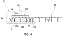
- the resisting force imparting portion 30 has frictionally slidable members 34, 35 and a resisting force adjustment bolt 36.
- the preceding spiral pipe portion 91 is caught between the frictionally slidable members 34, 35 respectively from the inner peripheral side and the outer peripheral side thereof.
- the frictionally slidable member 34 on the inner peripheral side has a plate configuration.
- a length of the frictionally slidable member 34 along the width direction of the pipe-making apparatus 3 (right-left direction in FIG. 5 ) is generally the same as or slightly shorter than a width of the strip member 90.
- the frictionally slidable member 34 is disposed on the inner peripheral side of the preceding spiral pipe portion 91.
- the frictionally slidable member 35 on the outer peripheral side is disposed on the outer peripheral side of the preceding spiral pipe portion 91.
- the frictionally slidable member 35 on the outer peripheral side includes a base plate 35a and two (plural) frictionally slidable blocks 35b, 35b.
- the base plate 35a is disposed so as to be laid over the reinforcement ribs 95 and the first fitting portion 93 of the distal one-turn portion 91a of the preceding spiral pipe portion 91.
- the frictionally slidable blocks 35b are disposed on a surface (upper surface in FIG. 6 ) of the base plate 35a facing the frictionally slidable member 34.
- the frictionally slidable block 35b has a quadrangular cross-sectional configuration and extends in the direction of movement of the pipe-making apparatus 3 (direction orthogonal to the plane of FIG. 6 ).
- Each of the frictionally slidable blocks 35b is fitted between the two reinforcement ribs 95 of the preceding spiral pipe portion 91.
- a surface (upper surface in FIG. 6 ) of the frictionally slidable block 35b facing the frictionally slidable member 34 is abutted against a back surface (under surface in FIG. 6 ) of the strip body 90a of the preceding spiral pipe portion 91.
- Opposite side surfaces of the frictionally slidable block 35b in a width direction are respectively abutted against the reinforcement ribs 95.
- the frictionally slidable block 35b is held so as to be movable with respect to the preceding spiral pipe portion 91 in the winding direction (direction orthogonal to the plane of FIG. 6 ) and immovable in the width direction.
- the frictionally slidable blocks 35b constitute a "second retainer portion".
- the frictionally slidable blocks 35b i.e. the second retainer portion 35b and the first retainer portion 25b are disposed spaced from each other in the direction of movement of the pipe-making apparatus 3 (winding direction of the preceding spiral pipe portion 91).
- the retainer portions 25b, 35b constitute "retainer".
- the body frame 3a is provided with the resisting force adjustment bolt 36 (resisting force adjustment means).
- the resisting force adjustment bolt 36 resisting force adjustment means.
- the frictionally slidable member 34 is abutted against an inner peripheral surface of the strip body 90a of the preceding spiral pipe portion 91.
- a pressing force is applied to the frictionally slidable member 35 on the outer peripheral side.
- the rehabilitation pipe 9 is made in the following manner by the pipe-making apparatus 3.
- the strip member 90 (following strip portion 92) is introduced into the pipe-making apparatus 3 from the start manhole 4 via an inside of the preceding spiral pipe portion 91.
- the following strip portion 92 is curled beforehand. Thereby, the following strip portion 92 can be easily put into the inside of the preceding spiral pipe portion 91 and can be easily introduced into the pipe-making apparatus 3.
- the following strip portion 92 is pushed toward the joining step position 20p by rotationally driving the propelling roller 13 of the propulsive reaction force imparting portion 10. Specifically, the following strip portion 92 is pushed from in front (left side in FIG. 3 ) of the joining step position 20p in the direction of movement toward the upstream side (returning side) in the winding direction of the strip member 90. Thereby, a propulsive reaction force F 10 for the pipe-making apparatus 3 to move forward in the winding direction can be obtained. By the propulsive reaction force F 10 , the pipe-making apparatus 3 can be moved forward (self-propelled) in the left direction in FIG. 3 with respect to the preceding spiral pipe portion 91 that is fixed, and thereby the pipe-making apparatus 3 can be moved forward (self-propelled) in the clockwise direction in FIG. 2 .
- the following strip portion 92 is successively fed between the fitting roller 23 and the fitting receiver 25 (joining step position 20p) of the fitting force imparting portion 20. Then the second fitting portion 94 of the following strip portion 92 is pressed into the first fitting portion 93 of the adjacent turn portion 91b of the preceding spiral pipe portion 91 by the fitting roller 23 and the fitting receiver 25. Thereby, as shown in chain double-dashed lines in FIG. 4 (b) , the second fitting portion 94 of the following strip portion 92, thereby of the portion continuing to the following strip portion 91e, is fitted into the first fitting portion 93 of the adjacent turn portion 91b. In this manner, while the strip member 90 is spirally wound, edges of adjacent turns of the strip member 90 are joined.
- a diameter of the preceding spiral pipe portion 91 tends to shrink.
- the causes thereof may include the following strip portion 92 being bent to a relatively great degree when being introduced to the pipe-making apparatus 3 and the following strip portion 92 being curled.
- the frictionally slidable members 34, 35 of the resisting force imparting portion 30 is frictionally slid along the preceding spiral pipe portion 91 and sliding friction is generated between the resisting force imparting portion 30 and the preceding spiral pipe portion 91.
- resisting force F 30 toward forward in the winding direction is imparted from the resisting force imparting portion 30 to the preceding spiral pipe portion 91.
- Direction of the resisting force F 30 is opposite to the direction of the propulsive reaction force F 10 along the winding direction.
- An imparting position of the resisting force F 30 is on the upstream side (returning side) in the winding direction of the strip member 90 with respect to an imparting position of the propulsive reaction force F 10 .
- a diameter-expanding effect works on the preceding spiral pipe portion 91.
- Mechanism of the diameter-expanding effect may be that a compressive stress is generated in a portion of the following strip portion 92 between the propulsive reaction force imparting portion 10 and the fitting force imparting portion 20 and the compressive stress is released in the distal one-turn portion 91a.
- the following strip portion 92 may be slid toward the joining step position 20p through a distance corresponding to a difference between the distance the pipe-making apparatus 3 is moved forward and the rotated distance of the propelling roller 13.
- a magnitude of the resisting force F 30 may be set so as to allow the pipe-making apparatus 3 to move forward and at the same time to allow the preceding spiral pipe portion 91 to expand the diameter thereof (diameter-variable).
- a diameter-shrinking effect of the preceding spiral pipe portion 91 itself may be counter-vailed or diminished by the diameter-expanding effect mentioned above. Thereby, the diameter of the preceding spiral pipe portion 91 may be maintained constant or an amount of shrinkage may be reduced. Moreover, by making the diameter-expanding effect greater than the diameter-shrinking effect, the preceding spiral pipe portion 91 can be pressed strongly against the inner wall of the existing pipe 1.
- the chain double-dashed lines in FIG. 2 indicate the preceding spiral pipe portion 91 in a diameter-expanded state assuming that the preceding spiral pipe portion 91 is not restricted by the existing pipe 1.
- a diameter shrinkage limiting frame such as the annular frame of Patent Document 1 and the radial frame of Patent Document 2 is not required.
- the body frame 3a it is not required for the body frame 3a to have an annular configuration extending along the inner wall of the existing pipe 1 or to radially extend toward the inner wall of the existing pipe 1.
- the pipe-making apparatus 3 can be downsized.
- the pipe-making apparatus 3 can be further downsized. As a result, even if an inner diameter of the existing pipe 1 is small, or even if the existing pipe 1 has an irregular cross-section portion having a steeply curving (large curvature) portion such as an angular portion or a bent portion, such existing pipe can be sufficiently treated and the rehabilitation pipe 9 can be surely lined along an inner peripheral surface of the existing pipe 1.
- the magnitude of the resisting force F 30 can be adjusted.
- the magnitude of the resisting force F 30 can be set at any value in a stepless fashion.
- the rehabilitation pipe 9 can be expanded or shrink according to changes of the inner diameter of the existing pipe 1 such as when the inner diameter of the existing pipe 1 changes depending on a position in an axial direction.
- the rehabilitation pipe 9 can be expanded or shrink to accommodate such portion.
- the pipe-making apparatus 3 can be prevented from being rotated with respect to the preceding spiral pipe portion 91 by the abutment of the first retainer portion 25b against the reinforcement rib 95 and the abutment of the frictionally slidable block 35b (second retainer portion) against the reinforcement rib 95.
- the pipe-making apparatus 3 can be positioned in an axial direction of the preceding spiral pipe portion 91 (right-left direction in FIGS. 5 and 6 ) by the abutment of the retainer portions 25b, 35b against the reinforcement ribs 95.
- FIG. 7 shows a second embodiment of the present invention.
- a fluid pressure cylinder 37 is provided as a resisting force adjustment means of a resisting force imparting portion 30B.
- the fluid pressure cylinder 37 may be a hydraulic cylinder or may be a pneumatic cylinder.
- a resisting force F 30 By pressing a frictionally slidable member 34 against a preceding spiral pipe portion 91 by the fluid pressure cylinder 37, a resisting force F 30 can be generated.
- magnitude of the resisting force F 30 can be adjusted in a stepped fashion or in a stepless fashion.
- the magnitude of the resisting force F 30 can also be adjusted by remote control.
- the output of the fluid pressure cylinder 37, thereby the magnitude of the resisting force F 30 may be set in a two-step selection of a value at which a diameter of the preceding spiral pipe portion 91 is expanded and a value at which the diameter of the preceding spiral pipe portion 91 is maintained constant taking into account a diameter-shrinking effect of the preceding spiral pipe portion 91 itself.
- the output of the fluid pressure cylinder 37, thereby the magnitude of the resisting force F 30 may be set in a two-step selection of the value at which the diameter of the preceding spiral pipe portion 91 is maintained constant and a value at which the diameter of the preceding spiral pipe portion 91 shrinks.
- the output of the fluid pressure cylinder 37, thereby the magnitude of the resisting force F 30 may be set in a three-step selection of the value at which the diameter of the preceding spiral pipe portion 91 is expanded, the value at which the diameter of the preceding spiral pipe portion 91 is maintained constant and the value at which the diameter of the preceding spiral pipe portion 91 shrinks. Furthermore, the output of the fluid pressure cylinder 37 may be stopped, and the magnitude of the resisting force F 30 may be brought to zero.
- a rehabilitation pipe 9 can be surely expanded or shrink according to changes of an inner diameter of an existing pipe 1 or a raised portion or a depressed portion or the like of the existing pipe 1.
- FIG. 8 shows a third embodiment of the present invention.
- a resisting force imparting portion 30C is composed of a pair of resistive rollers 33, 33.
- the resistive rollers 33, 33 and thereby the resisting force imparting portion 30C are disposed in a similar position to the resisting force imparting portion 30 of the first embodiment ( FIG. 3 ).
- An axis of the resistive roller 33 is oriented in a width direction of the pipe-making apparatus 3C (direction orthogonal to the plane of FIG. 8 ) in parallel to an axis of propelling rollers 13.
- a preceding spiral pipe portion 91 is caught between the resistive rollers 33, 33 from an inner peripheral side and an outer peripheral side.
- a rotational drive mechanism such as a motor is connected to at least one of the resistive rollers 33, 33.
- the resistive roller 33 is rotationally driven by the rotational drive mechanism in a direction opposite to the propelling roller 13.
- a resisting force F 30 toward forward in a winding direction (leftward in FIG. 3 ) is imparted to a distal one-turn portion 91a of the preceding spiral pipe portion 91.
- a diameter-expanding effect can be imparted to the preceding spiral pipe portion 91 by the resisting force F 30 and by the propulsive reaction force F 10 to a following strip portion 92 by the propelling roller 13.
- the resisting force F 30 can be increased or decreased by adjusting a number of rotation of the resistive roller 33, etc. Thereby, the diameter-expanding effect can be enhanced or reduced.
- the resistive roller 33 may be freely rotated by contact with the preceding spiral pipe portion 91 and a frictional resistance generator may be disposed in a rotary shaft or other portion of the resistive roller 33. In this case, the rotational drive mechanism for the resistive roller 33 may be omitted.
- the pipe-making apparatus 3C may be positioned in a width direction of the distal one-turn portion 91a (direction orthogonal to the plane of FIG. 8 ) by abutting an end surface of the resistive roller 33 on an outer peripheral side (under side in FIG. 8 ) against an enforcement rib 95 of the preceding spiral pipe portion 91 or by providing the resistive roller 33 with a flange and abutting the flange against the enforcement rib 95.
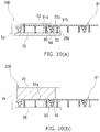
- FIGS. 9 and 10 show a fourth embodiment of the present invention.
- a fitting roller 23 ( FIG. 3 ) is omitted from a joining portion 20D and a fitting assistive roller 26 is provided in place of the fitting roller 23.
- the fitting assistive roller 26 is disposed on an inner peripheral side of a preceding spiral pipe portion 91 at a position shifted rearward with respect to a fitting receiver 25 in a direction of movement (right side in FIG. 9 ) of a pipe-making apparatus 3.
- An axis of the fitting assistive roller 26 is oriented to a width direction of the pipe-making apparatus 3D (direction orthogonal to the plane of FIG. 9 ) in parallel to an axis of a propelling roller 13.
- the fitting assistive roller 26 is freely rotatable about its own axis. It is not required that the fitting assistive roller 26 should be connected to a rotational drive mechanism such as a motor.
- a following strip portion 92 is pressed toward a joining step position 20p in the fitting receiver 25.
- a second fitting portion 94 of the following strip portion 92 and a first fitting portion 93 of an adjacent turn portion 91b of the preceding spiral pipe portion 91 can be fitted.
- the fitting assistive roller 26 may be omitted.
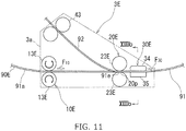
- FIGS. 11 to 13 show a fifth embodiment of the present invention.
- a pipe-making apparatus 3E according to the fifth embodiment includes a propulsive reaction force imparting portion 10E, a fitting force imparting portion 20E, a resisting force imparting portion 30E and a following strip portion guiding roller 43.
- the propulsive reaction force imparting portion 10E is disposed in a similar position to the resisting force imparting portion 30 of the first embodiment ( FIG. 3 ).
- the propulsive reaction force imparting portion 10E is disposed spaced from a joining step position 20p in front of the joining step position 20p in a direction of movement of the pipe-making apparatus 3E (leftward in FIG. 11 ) and is disposed on a distal one-turn portion 91a of a preceding spiral pipe portion 91.
- the propulsive reaction force imparting portion 10E has a pair of propelling rollers 13E, 13E.
- An axis of the propelling roller 13E is oriented in a width direction of the pipe-making apparatus 3E (direction orthogonal to the plane of FIG. 11 ).
- a length of a shaft of the propelling roller 13E is generally same as a width dimension of a strip member 90E.
- the preceding spiral pipe portion 91 is caught between the pair of propelling rollers 13E, 13E from an inner peripheral side and an outer peripheral side.
- a rotational drive mechanism (not shown) such as a motor is connected to at least one of the propelling rollers 13E, 13E.
- the propelling roller 13E is rotationally driven by the rotational drive mechanism such that the preceding spiral pipe portion 91 is pushed to a returning side (right side in FIG. 11 ) in a winding direction toward the joining step position 20p.
- a pair of following strip portion guiding rollers 43, 43 are disposed at a position spaced from the propulsive reaction force imparting portion 10E inside with respect to the propulsive reaction force imparting portion 10E in a radial direction of an existing pipe 1 (upper side in FIG. 11 ). That is to say, the following strip portion guiding roller 43 is disposed at a similar position to the propulsive reaction force imparting portion 10 of the first embodiment ( FIG. 3 ).
- An axis of the following strip portion guiding roller 43 is oriented to a width direction of the pipe-making apparatus 3E (direction orthogonal to the plane of FIG. 11 ).
- the following strip portion guiding roller 43 is freely rotatable about its own axis. It is not required that the following strip portion guiding roller 43 should be connected to a rotational drive mechanism such as a motor.
- a following strip portion 92 is caught between the pair of following strip portion guiding rollers 43, 43 from opposite sides.
- the fitting force imparting portion 20E is disposed at the joining step position 20p.
- the fitting force imparting portion 20E has a pair of fitting rollers 23E, 23E.
- An axis of the fitting roller 23E is oriented in the width direction of the pipe-making apparatus 3E (direction orthogonal to the plane of FIG. 11 ).
- a length of a shaft of the fitting roller 23E is generally the same as the width dimension of the strip member 90E.
- the fitting roller 23E is freely rotatable about its own axis. It is not required that the fitting roller 23E should be connected to a rotational drive mechanism such as a motor.
- the following strip portion 92 is inserted between the pair of fitting force imparting portions 20E, 20E at the joining step position 20p. Adjacent edges of the following strip portion 92 and an adjacent turn portion 91b of the preceding spiral pipe portion 91 are joined.
- the resisting force imparting portion 30E is disposed at a position spaced from the fitting force imparting portions 20E (joining step position 20p) at the rear with respect to the fitting force imparting portions 20E in in the direction of movement of the pipe-making apparatus 3E (rightward in FIG. 11 ).
- the propulsive reaction force imparting portion 10E and the resisting force imparting portion 30 are disposed on opposite sides from each other with respect to the joining step position 20p in the direction of movement of the pipe-making apparatus 3E (circumferential direction of the preceding spiral pipe portion 91).
- the resisting force imparting portion 30E is disposed forward (downstream side) of the propulsive reaction force imparting portion 10E in the winding direction.
- the resisting force imparting portion 30E includes a frictionally slidable member 34 on the inner peripheral side and a frictionally slidable member 35 on the outer peripheral side.
- Width dimensions of the frictionally slidable members 34, 35 are generally the same as or shorter than the width dimension of the strip member 90E.
- a distal one-turn portion 91a of the preceding spiral pipe portion 91 is caught between the frictionally slidable members 34, 35.
- a sub lock setting protrusion 32 is disposed in one end portion (right end portion in FIG.
- an extended edge portion 98 is formed in the strip member 90E of the fifth embodiment.
- the extended edge portion 98 obliquely extends from a first fitting portion 93 toward outside in a width direction (right-left direction in FIG. 13 ) of the strip member 90E and outside (under side in FIG. 13 ) in a radial direction of a rehabilitation pipe 9.
- the extended edge portion 98 is fitted into a step 95d between a main portion 95a and a protruded portion 95b of adjacent turns of a reinforcement rib 95 of the rehabilitation pipe 9.
- the first fitting portion 93 and a second fitting portion 94 fitted together constitute a main lock 9a.
- the rehabilitation pipe 9 is made into a pipe in the following manner.
- the propelling rollers 13E, 13E of the propulsive reaction force imparting portion 10E are rotationally driven to push the preceding spiral pipe portion 91 to the returning side (right side in FIG. 11 ) in the winding direction toward the joining step position 20p.
- the propulsive reaction force F 10 the pipe-making apparatus 3E is moved forward in a direction of movement in the winding direction (left direction in FIG. 11 ) with respect to the preceding spiral pipe portion 91 that is fixed.
- the following strip portion 92 is successively fed between the fitting rollers 23E (joining step position 20p) of the fitting force imparting portion 20E.
- the second fitting portion 94 of the following strip portion 92 is fitted with the first fitting portion 93 of the adjacent turn portion 91b of the preceding spiral pipe portion 91, and the main lock 9a is locked.
- the extended edge portion 98 of the adjacent turn portion 91b is hooked to a distal end portion of the protruded portion 95b of the following strip portion 92.
- the extended edge portion 98 is not moved far enough to be fitted to the step 95d, and the sub lock 9b is not locked.
- the resisting force imparting portion 30E is frictionally slid along the preceding spiral pipe portion 91.
- a resisting force F 30 in a direction opposite to the direction of the propulsive reaction force F 10 in the winding direction, i.e. toward forward in the winding direction (left side in FIG. 11 ) is imparted to the preceding spiral pipe portion 91.
- An imparting position of the resisting force F 30 in the preceding spiral pipe portion 91 is forward (downstream side) of an imparting position of the propulsive reaction force F 10 in the winding direction.
- the fitting portions 93, 94 of the main lock 9a can be slid in the winding direction (circumferential direction of the preceding spiral pipe portion 91) since the sub lock 9b is not in a locked state between the fitting force imparting portion 20E and the resisting force imparting portion 30E. Thereby, the diameter-shrinking effect can be surely obtained.
- the sub lock setting protrusion 32 presses the extended edge portion 98 toward the inner peripheral side (upper side in FIG. 13 (b) ). Thereby, as indicated by the solid lines in FIG. 13 (b) , the extended edge portion 98 is fitted into the step 95d. Thereby, the sub lock 9b is locked. As a result, the slipping can be restrained in an upstream side (returning side) in the winding direction with respect to the resisting force imparting portion 30E.
- the strip member 90E can be spirally wound around the outer peripheral surface of the pole 5 in a closely contacted manner by using the pipe-making apparatus 3E.
- FIG. 15 shows a sixth embodiment of the present invention.
- a pipe-making apparatus 3F according to the sixth embodiment includes a propulsive reaction force imparting portion 10F, a fitting force imparting portion 20 and a resisting force imparting portion 30F.
- the propulsive reaction force imparting portion 10F has a pair of propelling rollers 13F, 13F and the propulsive reaction force imparting portion 10F is disposed spaced from a joining step position 20p of the fitting force imparting portion 20 in front of the joining step position 20p (left side in FIG. 15 ) in a direction of movement of the pipe-making apparatus 3F.
- a preceding spiral pipe portion 91 is caught between the propelling rollers 13F, 13F.
- the propelling roller 13F is rotationally driven by a rotational drive mechanism (not shown) so as to push the preceding spiral pipe portion 91 toward the joining step position 20p. With the pressing force working as a reaction force, the pipe-making apparatus 3F is propelled leftward in FIG. 15 .
- the resisting force imparting portion 30F is disposed at the same position as the propulsive reaction force imparting portion 10 of the first embodiment ( FIG. 3 ). Specifically, the resisting force imparting portion 30F is located spaced from the joining step position 20p in front of the joining step position 20p (left side in FIG. 15 ) in the direction of movement of the pipe-making apparatus 3F and in a radial direction (vertical direction in FIG. 15 ) of the preceding spiral pipe portion 91. A following strip portion 92 is caught between the pair of resisting rollers 33F, 33F of the resisting force imparting portion 30F. The resisting roller 33F is rotationally driven by the rotational drive mechanism (not shown) so as to push the following strip portion 92 in a direction opposite to the joining step position 20p.
- the pipe-making apparatus 3F ( FIG. 15 ) is substantially the same as the pipe-making apparatus 3C of the third embodiment ( FIG. 8 ) in structure.
- the pipe-making apparatus 3F ( FIG. 15 ) can be attained. Accordingly, by using one pipe-making apparatus 3C, the diameter-expanding effect and the diameter-shrinking effect can be exerted by rotating the propelling roller 13 and the resistive rollers 33 normally or reversely.
- FIGS. 16 and 17 show a seventh embodiment of the present invention.
- the seventh embodiment is a modified embodiment in which the resisting force imparting portion and the strip member are modified.
- a strip member 90G of the seventh embodiment is provided with a reinforcement strip 99.
- the reinforcement strip 99 is made of a metal plate such as a steel plate.
- the reinforcement strip 99 has a generally M-shaped cross-section.
- the reinforcement strip 99 includes a pair of grooves 99b, 99b and a central convex frame portion 99a having a U-shaped cross-section between the grooves 99b, 99b.
- the reinforcement strip 99 is fitted between two reinforcement ribs 95G of the strip member 90G.
- a resisting force imparting portion 30G of the seventh embodiment has a body 31 and a pair of frictionally slidable members 38, 39.
- the body 31 is fixed to a body frame 3a.
- a fixed frictionally slidable member 38 and a movable frictionally slidable member 39 are protruded from the body 31 toward the strip member 90G.
- the fixed frictionally slidable member 38 and the movable frictionally slidable member 39 are spaced from each other in a width direction of the body 31 (right-left direction in FIG. 16 ).
- the fixed frictionally slidable member 38 is fixed to the body 31.
- the movable frictionally slidable member 39 is slidable in the width direction of the body 31, thereby movable toward and away from the fixed frictionally slidable member 38.
- the body 31 is provided with a resisting force adjustment bolt 36 (resisting force adjustment means). Position of the movable frictionally slidable member 39 in the width direction of the body 31 can be adjusted by the resisting force adjustment bolt 36.
- the resisting force imparting portion 30G is disposed on an outer peripheral side (under side in FIG. 16 ) of the strip member 90G.
- the fixed frictionally slidable member 38 and the movable frictionally slidable member 39 are respectively inserted in the pair of grooves 99b of the reinforcement strip 99.
- the movable frictionally slidable member 39 is moved closer to the fixed frictionally slidable member 38 by the resisting force adjustment bolt 36, and thereby the frictionally slidable members 38, 39 are respectively pressed against opposite side portions of the central convex frame portion 99a of the.
- friction is generated between the reinforcement strip 99 and the frictionally slidable members 38, 39, and a resisting force F 30 acts therebetween.
- the resisting force imparting portion 30G may be provided with a fluid pressure cylinder 37 (refer to FIG. 7 ) instead of the resisting force adjustment bolt 36, and the pressing force of the movable frictionally slidable member 39 and thereby the resisting force F 30 of the movable frictionally slidable member 39 may be adjusted by the fluid pressure cylinder 37.
- the propulsive reaction force imparting portion may be disposed in the following strip portion 92.
- the resisting force imparting portion may be disposed in the following strip portion 92 at a point closer to the joining step position 20p than the propulsive reaction force imparting portion.
- the body frame 3a may be provided with retainer (first and second retainer portions) for positioning and for preventing rotation.
- the resisting force imparting portion 30 of the fourth embodiment may be used in place of the resisting force imparting portion 30C of the third embodiment ( FIG. 8 ).
- the fitting force imparting portion 20E of the fifth embodiment may be used as the fitting force imparting portion in other embodiments.
- the strip member 90E ( FIG. 13 ) of the fifth embodiment may be used as the strip member in embodiments other than the fifth embodiment.
- a strip member 90 ( FIG. 4 ) similar to the strip member of the first embodiment, etc. may be used as the strip member in the fifth embodiment.
- the resisting force imparting portion 30G of the seventh embodiment may be used as the resisting force imparting portion in the first to the sixth embodiments.
- the location of the resisting force imparting portion 30E in the preceding spiral pipe portion 91 may be moved to the returning side (upstream side) in the winding direction with respect to the location of the propulsive reaction force imparting portion 10E so that the diameter-expanding effect may be imparted to the preceding spiral pipe portion 91.
- the propulsive reaction force imparting portion 10E and the resisting force imparting portion 30E may be disposed on the same side (preferably, in front in the direction of movement) in the circumferential direction of the spiral pipe 9 with respect to the joining step position 20p.
- a joining portion corresponding to the fitting portions 93, 94 of the strip member 90 may be manufactured as a separate component independent of the strip body 90a.
- the joining portion may be joined with the strip body 90a before the pipe-making or during the pipe-making.
- the joining portion may extend over edges of adjacent turns of the strip body 90a and may be joined with these edges.
- the present invention may be applied to a rehabilitation work of an aged existing pipe such as a sewer pipe, a water supply pipe, an agricultural water pipe and a gas pipe.
Landscapes
- Engineering & Computer Science (AREA)
- General Engineering & Computer Science (AREA)
- Mechanical Engineering (AREA)
- Manufacturing & Machinery (AREA)
- Lining Or Joining Of Plastics Or The Like (AREA)
- Pipe Accessories (AREA)
Applications Claiming Priority (3)
| Application Number | Priority Date | Filing Date | Title |
|---|---|---|---|
| JP2015091628 | 2015-04-28 | ||
| JP2016059941 | 2016-03-24 | ||
| PCT/JP2016/063199 WO2016175243A1 (ja) | 2015-04-28 | 2016-04-27 | 螺旋管の製管装置及び製管方法 |
Publications (3)
| Publication Number | Publication Date |
|---|---|
| EP3290182A1 true EP3290182A1 (de) | 2018-03-07 |
| EP3290182A4 EP3290182A4 (de) | 2018-12-12 |
| EP3290182B1 EP3290182B1 (de) | 2023-01-25 |
Family
ID=57199494
Family Applications (1)
| Application Number | Title | Priority Date | Filing Date |
|---|---|---|---|
| EP16786519.5A Active EP3290182B1 (de) | 2015-04-28 | 2016-04-27 | Rohrherstellungsvorrichtung und rohrherstellungsverfahren für spiralrohr |
Country Status (6)
| Country | Link |
|---|---|
| US (1) | US10920918B2 (de) |
| EP (1) | EP3290182B1 (de) |
| JP (1) | JP6518324B2 (de) |
| KR (1) | KR101996746B1 (de) |
| AU (1) | AU2016253716C1 (de) |
| WO (1) | WO2016175243A1 (de) |
Cited By (3)
| Publication number | Priority date | Publication date | Assignee | Title |
|---|---|---|---|---|
| EP3437836A4 (de) * | 2016-03-31 | 2019-10-30 | Sekisui Chemical Co., Ltd. | Rohrherstellungsvorrichtung und rohrherstellungsverfahren |
| EP3508328A4 (de) * | 2016-08-30 | 2020-06-24 | Sekisui Chemical Co., Ltd. | Rohrherstellungsvorrichtung für spiralrohr |
| NO20230764A1 (en) * | 2022-07-26 | 2024-01-29 | Odfjell Oceanwind As | Bending machine for manufacturing a reinforced pipe |
Families Citing this family (14)
| Publication number | Priority date | Publication date | Assignee | Title |
|---|---|---|---|---|
| KR102219609B1 (ko) | 2017-03-01 | 2021-02-25 | 세키스이가가쿠 고교가부시키가이샤 | 나선관용 띠상 부재 및 기설관의 갱생 방법 |
| JP6927778B2 (ja) * | 2017-07-18 | 2021-09-01 | 積水化学工業株式会社 | 螺旋管の製管装置 |
| JP6927782B2 (ja) * | 2017-07-19 | 2021-09-01 | 積水化学工業株式会社 | 螺旋管の製管装置 |
| JP2019025839A (ja) * | 2017-08-01 | 2019-02-21 | 積水化学工業株式会社 | 既設管の更生方法及び支保材 |
| CN107489852B (zh) * | 2017-08-14 | 2023-12-01 | 湖南大麓科技有限公司 | 螺旋缠绕非开挖修复轴向编管装置 |
| JP6927828B2 (ja) * | 2017-09-27 | 2021-09-01 | 積水化学工業株式会社 | 製管装置および製管方法 |
| JP6936115B2 (ja) * | 2017-11-06 | 2021-09-15 | 積水化学工業株式会社 | 螺旋管の製管装置 |
| JP1616663S (de) | 2018-02-27 | 2018-10-29 | ||
| JP7352426B2 (ja) * | 2019-09-26 | 2023-09-28 | 積水化学工業株式会社 | 螺旋管の製管方法及び製管装置 |
| JP7352427B2 (ja) * | 2019-09-26 | 2023-09-28 | 積水化学工業株式会社 | 螺旋管の製管方法及び製管装置 |
| JP7449146B2 (ja) * | 2020-04-14 | 2024-03-13 | 積水化学工業株式会社 | 製管装置 |
| JP7663479B2 (ja) | 2021-11-11 | 2025-04-16 | 積水化学工業株式会社 | 螺旋管の製管装置 |
| CN115592617B (zh) * | 2022-12-15 | 2023-04-07 | 江苏银环精密钢管有限公司 | 一种多层螺旋管套装工装及使用方法 |
| KR102907896B1 (ko) * | 2025-03-04 | 2026-01-05 | (주)캐어콘 | 제관용 프로파일 및 이를 이용한 제관공법 |
Family Cites Families (40)
| Publication number | Priority date | Publication date | Assignee | Title |
|---|---|---|---|---|
| US3601570A (en) * | 1967-06-14 | 1971-08-24 | Pacific Roller Die Co Inc | Helical pipe-forming and welding apparatus method |
| JPS5310850B2 (de) | 1971-12-13 | 1978-04-17 | ||
| US4070886A (en) * | 1977-01-05 | 1978-01-31 | Adrianus Marinus Nyssen | Spiral pipe forming machine with device for aligning spiralling rolls |
| US4541887A (en) * | 1979-08-30 | 1985-09-17 | Ameron Inc. | Apparatus for longitudinally reinforcing continuously generated plastic pipe |
| US4436239A (en) * | 1981-04-29 | 1984-03-13 | Nippon Steel Corporation | Method and apparatus for manufacturing spiral pipe |
| US4544426A (en) * | 1983-10-24 | 1985-10-01 | Shaw Industries Ltd. | Method and apparatus for applying a coating material to a pipe |
| US4567742A (en) * | 1984-01-10 | 1986-02-04 | Spiro America Inc. | Ribbed spiral pipe producing machine |
| JPS6449618A (en) * | 1987-08-20 | 1989-02-27 | Sekisui Chemical Co Ltd | Engineering method for lining of existing pipe |
| CH679023A5 (de) * | 1989-06-13 | 1991-12-13 | Suter Emil Maschf | |
| JP3217076B2 (ja) | 1991-01-30 | 2001-10-09 | 積水化学工業株式会社 | 管路内周面のライニング方法 |
| WO1993006986A1 (en) * | 1991-10-02 | 1993-04-15 | Rib Loc Australia Pty. Ltd. | Loop machine for helically winding strip |
| US5261995A (en) * | 1992-12-28 | 1993-11-16 | Shaw Industries Ltd. | Pipe wrapping apparatus and method |
| JP3233542B2 (ja) * | 1995-02-14 | 2001-11-26 | 株式会社オーシーシー | 金属管被覆光ファイバケーブルの製造方法及び製造装置 |
| IT1281260B1 (it) * | 1995-04-27 | 1998-02-17 | Sasib Spa | Metodo e dispositivo per imballare prodotti, in particolare astiformi, come sigarette, o simili in un foglio d'involucro |
| JP3657056B2 (ja) | 1996-05-23 | 2005-06-08 | 積水化学工業株式会社 | 既設管ライニング用プロファイル |
| JP3163054B2 (ja) * | 1997-01-28 | 2001-05-08 | 積水化学工業株式会社 | 管渠内用ライニング施工装置並びに管渠内におけるライニング施工方法 |
| AUPP610698A0 (en) | 1998-09-22 | 1998-10-15 | Rib Loc Australia Pty. Ltd. | Method and apparatus for direct lining of conduits |
| US6164702A (en) * | 1999-06-07 | 2000-12-26 | Adc Acquisition Company | Reinforced thermoplastic pipe couping |
| US6773773B2 (en) * | 1999-06-14 | 2004-08-10 | Adc Acquisition Company | Reinforced thermoplastic pipe manufacture |
| JP3990862B2 (ja) * | 1999-11-22 | 2007-10-17 | キヤノン株式会社 | 管状フィルムの製造方法及び製造装置 |
| WO2002058861A1 (en) * | 2001-01-26 | 2002-08-01 | Ovalformer Llc | Machine for producing spiral seamed pipe |
| US20030230127A1 (en) * | 2002-06-18 | 2003-12-18 | Helix International, Inc. | Perforated spiral pipe |
| JP4674082B2 (ja) | 2004-12-27 | 2011-04-20 | 積水化学工業株式会社 | 既設管のライニング施工方法及び製管機 |
| US7451629B2 (en) * | 2006-04-05 | 2008-11-18 | Formtek, Inc. | Spiral pipe machine |
| JP4767155B2 (ja) | 2006-11-26 | 2011-09-07 | 足立建設工業株式会社 | 管渠におけるライニング用管状体の製管装置及びその製管方法 |
| JP4866428B2 (ja) | 2006-12-18 | 2012-02-01 | 積水化学工業株式会社 | 製管装置およびこの製管装置を用いた既設管の更生工法 |
| KR20120104411A (ko) * | 2007-04-04 | 2012-09-20 | 스미토모 고칸 가부시키가이샤 | 굽힘가공제품의 제조 방법, 제조 장치 및 연속 제조 장치 |
| AU2008273303B2 (en) * | 2007-07-12 | 2012-04-19 | Sekisui Chemical Co., Ltd. | Device for curling strip member with reinforcing material, method for making spiral pipe, and device for making spiral pipe |
| JP5166896B2 (ja) | 2008-01-31 | 2013-03-21 | 積水化学工業株式会社 | 製管装置および製管方法 |
| SG173734A1 (en) * | 2009-02-20 | 2011-09-29 | Fyfe Co Llc | Systems and methods of reinforcing a pipe using fiber bundles |
| JP5602737B2 (ja) * | 2009-07-27 | 2014-10-08 | 積水化学工業株式会社 | 製管機及び製管方法 |
| JP3163054U (ja) | 2010-05-18 | 2010-09-30 | 光数 小田桐 | お風呂に浮かべて湯水質改善を手軽に行う磁気入浴用品。 |
| WO2012108434A1 (ja) * | 2011-02-07 | 2012-08-16 | 積水化学工業株式会社 | 製管装置及び製管方法 |
| US8684628B2 (en) * | 2011-05-23 | 2014-04-01 | Sekisui Chemical Co., Ltd. | Winding apparatus |
| US20140216225A1 (en) * | 2011-09-07 | 2014-08-07 | Beltech Korea Inc. | Apparatus for manufacturing seamless bias fabrics using tubular fabrics |
| JP6170360B2 (ja) * | 2013-07-09 | 2017-07-26 | 積水化学工業株式会社 | 製管装置 |
| KR20150021240A (ko) * | 2013-08-20 | 2015-03-02 | 부경대학교 산학협력단 | 티그 용접용 용가재 성형 송급 장치 |
| WO2015186416A1 (ja) * | 2014-06-04 | 2015-12-10 | 積水化学工業株式会社 | 巻癖形成装置 |
| EP3153299B1 (de) * | 2014-06-04 | 2023-03-15 | Sekisui Chemical Co., Ltd. | Rohrherstellungsmaschine |
| TWI656020B (zh) * | 2014-09-02 | 2019-04-11 | 義大利商莫托雷斯紙業責任有限公司 | 用於藉由將帶狀材料捲繞一成型心軸來生產管體的機器 |
-
2016
- 2016-04-27 US US15/569,314 patent/US10920918B2/en active Active
- 2016-04-27 EP EP16786519.5A patent/EP3290182B1/de active Active
- 2016-04-27 JP JP2017515578A patent/JP6518324B2/ja active Active
- 2016-04-27 WO PCT/JP2016/063199 patent/WO2016175243A1/ja not_active Ceased
- 2016-04-27 AU AU2016253716A patent/AU2016253716C1/en active Active
- 2016-04-27 KR KR1020177032440A patent/KR101996746B1/ko active Active
Cited By (11)
| Publication number | Priority date | Publication date | Assignee | Title |
|---|---|---|---|---|
| EP3437836A4 (de) * | 2016-03-31 | 2019-10-30 | Sekisui Chemical Co., Ltd. | Rohrherstellungsvorrichtung und rohrherstellungsverfahren |
| EP3725495A1 (de) * | 2016-03-31 | 2020-10-21 | Sekisui Chemical Co., Ltd. | Rohrherstellungsvorrichtung und rohrherstellungsverfahren |
| US11015757B2 (en) | 2016-03-31 | 2021-05-25 | Sekisui Chemical Co., Ltd. | Pipe-making apparatus and pipe-making method |
| EP3508328A4 (de) * | 2016-08-30 | 2020-06-24 | Sekisui Chemical Co., Ltd. | Rohrherstellungsvorrichtung für spiralrohr |
| EP3812128A1 (de) | 2016-08-30 | 2021-04-28 | Sekisui Chemical Co., Ltd. | Rohrformungsvorrichtung für spiralrohr und rohrformungsverfahren |
| EP3812127A1 (de) | 2016-08-30 | 2021-04-28 | Sekisui Chemical Co., Ltd. | Rohrformungsvorrichtung für spiralrohr |
| US11148352B2 (en) | 2016-08-30 | 2021-10-19 | Sekisui Chemical Co., Ltd. | Pipe-forming apparatus for spiral pipe and pipe-forming method thereof |
| US11383427B2 (en) | 2016-08-30 | 2022-07-12 | Sekisui Chemical Co., Ltd. | Pipe-forming apparatus for spiral pipe and pipe-forming method thereof |
| US11602884B2 (en) | 2016-08-30 | 2023-03-14 | Sekisui Chemical Co., Ltd. | Pipe-forming apparatus for spiral pipe and pipe-forming method thereof |
| NO20230764A1 (en) * | 2022-07-26 | 2024-01-29 | Odfjell Oceanwind As | Bending machine for manufacturing a reinforced pipe |
| NO348670B1 (en) * | 2022-07-26 | 2025-04-28 | Odfjell Oceanwind As | Bending machine for manufacturing a reinforced pipe |
Also Published As
| Publication number | Publication date |
|---|---|
| US10920918B2 (en) | 2021-02-16 |
| AU2016253716C1 (en) | 2021-04-22 |
| AU2016253716B2 (en) | 2019-03-28 |
| US20180038541A1 (en) | 2018-02-08 |
| EP3290182B1 (de) | 2023-01-25 |
| JPWO2016175243A1 (ja) | 2018-02-15 |
| AU2016253716A1 (en) | 2017-12-14 |
| KR20170134728A (ko) | 2017-12-06 |
| WO2016175243A1 (ja) | 2016-11-03 |
| EP3290182A4 (de) | 2018-12-12 |
| JP6518324B2 (ja) | 2019-05-22 |
| KR101996746B1 (ko) | 2019-07-04 |
Similar Documents
| Publication | Publication Date | Title |
|---|---|---|
| EP3290182A1 (de) | Rohrherstellungsvorrichtung und rohrherstellungsverfahren für spiralrohr | |
| EP3608031B1 (de) | Rohrelemente | |
| JP6637593B2 (ja) | 製管装置および製管方法 | |
| JP7092518B2 (ja) | 螺旋管の製管方法、製管装置、及び帯状部材 | |
| JP6267327B2 (ja) | 製管装置およびこれを用いた製管方法 | |
| JP6940098B2 (ja) | 製管機、管体の製管方法および帯板状部材 | |
| JP2014104681A (ja) | ライニング工法および更生管路 | |
| JP7449146B2 (ja) | 製管装置 | |
| JP2014113793A (ja) | ライニング工法、それに用いる製管機および更生管路 | |
| JP2019059150A (ja) | 製管装置および製管方法 | |
| JP6133457B1 (ja) | 塑性加工機構を備えたライニング用製管装置及び該製管装置によるライニング施工方法 | |
| JP7684653B2 (ja) | 製管機および製管方法 | |
| JP2014104612A (ja) | ライニング工法および更生管路 | |
| JP2862341B2 (ja) | 既設管のライニング工法 | |
| JP7663479B2 (ja) | 螺旋管の製管装置 | |
| JP7768507B2 (ja) | 製管機及び更生管 | |
| JP7684654B2 (ja) | 製管機および製管方法 | |
| JP7613691B2 (ja) | 製管機および製管方法 | |
| JP3676475B2 (ja) | 既設管の更生方法 | |
| JP2002147650A (ja) | 管渠内のライニング施工法及びライニング材 | |
| JP6927778B2 (ja) | 螺旋管の製管装置 | |
| JPH0833183B2 (ja) | 既設管のライニング工法 | |
| JP2019018474A (ja) | 螺旋管の製管装置 | |
| JP6769809B2 (ja) | 螺旋管の製管装置 | |
| JP2026060385A (ja) | 既設管更生用製管装置 |
Legal Events
| Date | Code | Title | Description |
|---|---|---|---|
| STAA | Information on the status of an ep patent application or granted ep patent |
Free format text: STATUS: THE INTERNATIONAL PUBLICATION HAS BEEN MADE |
|
| PUAI | Public reference made under article 153(3) epc to a published international application that has entered the european phase |
Free format text: ORIGINAL CODE: 0009012 |
|
| STAA | Information on the status of an ep patent application or granted ep patent |
Free format text: STATUS: REQUEST FOR EXAMINATION WAS MADE |
|
| 17P | Request for examination filed |
Effective date: 20171108 |
|
| AK | Designated contracting states |
Kind code of ref document: A1 Designated state(s): AL AT BE BG CH CY CZ DE DK EE ES FI FR GB GR HR HU IE IS IT LI LT LU LV MC MK MT NL NO PL PT RO RS SE SI SK SM TR |
|
| AX | Request for extension of the european patent |
Extension state: BA ME |
|
| DAV | Request for validation of the european patent (deleted) | ||
| DAX | Request for extension of the european patent (deleted) | ||
| RIC1 | Information provided on ipc code assigned before grant |
Ipc: F16L 55/18 20060101ALI20181030BHEP Ipc: F16L 55/165 20060101ALI20181030BHEP Ipc: B29C 63/32 20060101AFI20181030BHEP |
|
| A4 | Supplementary search report drawn up and despatched |
Effective date: 20181114 |
|
| STAA | Information on the status of an ep patent application or granted ep patent |
Free format text: STATUS: EXAMINATION IS IN PROGRESS |
|
| 17Q | First examination report despatched |
Effective date: 20201112 |
|
| GRAP | Despatch of communication of intention to grant a patent |
Free format text: ORIGINAL CODE: EPIDOSNIGR1 |
|
| STAA | Information on the status of an ep patent application or granted ep patent |
Free format text: STATUS: GRANT OF PATENT IS INTENDED |
|
| INTG | Intention to grant announced |
Effective date: 20220829 |
|
| GRAS | Grant fee paid |
Free format text: ORIGINAL CODE: EPIDOSNIGR3 |
|
| GRAA | (expected) grant |
Free format text: ORIGINAL CODE: 0009210 |
|
| STAA | Information on the status of an ep patent application or granted ep patent |
Free format text: STATUS: THE PATENT HAS BEEN GRANTED |
|
| AK | Designated contracting states |
Kind code of ref document: B1 Designated state(s): AL AT BE BG CH CY CZ DE DK EE ES FI FR GB GR HR HU IE IS IT LI LT LU LV MC MK MT NL NO PL PT RO RS SE SI SK SM TR |
|
| REG | Reference to a national code |
Ref country code: GB Ref legal event code: FG4D |
|
| REG | Reference to a national code |
Ref country code: CH Ref legal event code: EP |
|
| REG | Reference to a national code |
Ref country code: DE Ref legal event code: R096 Ref document number: 602016077624 Country of ref document: DE |
|
| REG | Reference to a national code |
Ref country code: AT Ref legal event code: REF Ref document number: 1545635 Country of ref document: AT Kind code of ref document: T Effective date: 20230215 Ref country code: IE Ref legal event code: FG4D |
|
| REG | Reference to a national code |
Ref country code: LT Ref legal event code: MG9D |
|
| REG | Reference to a national code |
Ref country code: NL Ref legal event code: MP Effective date: 20230125 |
|
| REG | Reference to a national code |
Ref country code: AT Ref legal event code: MK05 Ref document number: 1545635 Country of ref document: AT Kind code of ref document: T Effective date: 20230125 |
|
| P01 | Opt-out of the competence of the unified patent court (upc) registered |
Effective date: 20230522 |
|
| PG25 | Lapsed in a contracting state [announced via postgrant information from national office to epo] |
Ref country code: NL Free format text: LAPSE BECAUSE OF FAILURE TO SUBMIT A TRANSLATION OF THE DESCRIPTION OR TO PAY THE FEE WITHIN THE PRESCRIBED TIME-LIMIT Effective date: 20230125 |
|
| PG25 | Lapsed in a contracting state [announced via postgrant information from national office to epo] |
Ref country code: RS Free format text: LAPSE BECAUSE OF FAILURE TO SUBMIT A TRANSLATION OF THE DESCRIPTION OR TO PAY THE FEE WITHIN THE PRESCRIBED TIME-LIMIT Effective date: 20230125 Ref country code: PT Free format text: LAPSE BECAUSE OF FAILURE TO SUBMIT A TRANSLATION OF THE DESCRIPTION OR TO PAY THE FEE WITHIN THE PRESCRIBED TIME-LIMIT Effective date: 20230525 Ref country code: NO Free format text: LAPSE BECAUSE OF FAILURE TO SUBMIT A TRANSLATION OF THE DESCRIPTION OR TO PAY THE FEE WITHIN THE PRESCRIBED TIME-LIMIT Effective date: 20230425 Ref country code: LV Free format text: LAPSE BECAUSE OF FAILURE TO SUBMIT A TRANSLATION OF THE DESCRIPTION OR TO PAY THE FEE WITHIN THE PRESCRIBED TIME-LIMIT Effective date: 20230125 Ref country code: LT Free format text: LAPSE BECAUSE OF FAILURE TO SUBMIT A TRANSLATION OF THE DESCRIPTION OR TO PAY THE FEE WITHIN THE PRESCRIBED TIME-LIMIT Effective date: 20230125 Ref country code: HR Free format text: LAPSE BECAUSE OF FAILURE TO SUBMIT A TRANSLATION OF THE DESCRIPTION OR TO PAY THE FEE WITHIN THE PRESCRIBED TIME-LIMIT Effective date: 20230125 Ref country code: ES Free format text: LAPSE BECAUSE OF FAILURE TO SUBMIT A TRANSLATION OF THE DESCRIPTION OR TO PAY THE FEE WITHIN THE PRESCRIBED TIME-LIMIT Effective date: 20230125 Ref country code: AT Free format text: LAPSE BECAUSE OF FAILURE TO SUBMIT A TRANSLATION OF THE DESCRIPTION OR TO PAY THE FEE WITHIN THE PRESCRIBED TIME-LIMIT Effective date: 20230125 |
|
| PG25 | Lapsed in a contracting state [announced via postgrant information from national office to epo] |
Ref country code: SE Free format text: LAPSE BECAUSE OF FAILURE TO SUBMIT A TRANSLATION OF THE DESCRIPTION OR TO PAY THE FEE WITHIN THE PRESCRIBED TIME-LIMIT Effective date: 20230125 Ref country code: PL Free format text: LAPSE BECAUSE OF FAILURE TO SUBMIT A TRANSLATION OF THE DESCRIPTION OR TO PAY THE FEE WITHIN THE PRESCRIBED TIME-LIMIT Effective date: 20230125 Ref country code: IS Free format text: LAPSE BECAUSE OF FAILURE TO SUBMIT A TRANSLATION OF THE DESCRIPTION OR TO PAY THE FEE WITHIN THE PRESCRIBED TIME-LIMIT Effective date: 20230525 Ref country code: GR Free format text: LAPSE BECAUSE OF FAILURE TO SUBMIT A TRANSLATION OF THE DESCRIPTION OR TO PAY THE FEE WITHIN THE PRESCRIBED TIME-LIMIT Effective date: 20230426 Ref country code: FI Free format text: LAPSE BECAUSE OF FAILURE TO SUBMIT A TRANSLATION OF THE DESCRIPTION OR TO PAY THE FEE WITHIN THE PRESCRIBED TIME-LIMIT Effective date: 20230125 |
|
| P02 | Opt-out of the competence of the unified patent court (upc) changed |
Effective date: 20230907 |
|
| REG | Reference to a national code |
Ref country code: DE Ref legal event code: R097 Ref document number: 602016077624 Country of ref document: DE |
|
| PG25 | Lapsed in a contracting state [announced via postgrant information from national office to epo] |
Ref country code: SM Free format text: LAPSE BECAUSE OF FAILURE TO SUBMIT A TRANSLATION OF THE DESCRIPTION OR TO PAY THE FEE WITHIN THE PRESCRIBED TIME-LIMIT Effective date: 20230125 Ref country code: RO Free format text: LAPSE BECAUSE OF FAILURE TO SUBMIT A TRANSLATION OF THE DESCRIPTION OR TO PAY THE FEE WITHIN THE PRESCRIBED TIME-LIMIT Effective date: 20230125 Ref country code: EE Free format text: LAPSE BECAUSE OF FAILURE TO SUBMIT A TRANSLATION OF THE DESCRIPTION OR TO PAY THE FEE WITHIN THE PRESCRIBED TIME-LIMIT Effective date: 20230125 Ref country code: DK Free format text: LAPSE BECAUSE OF FAILURE TO SUBMIT A TRANSLATION OF THE DESCRIPTION OR TO PAY THE FEE WITHIN THE PRESCRIBED TIME-LIMIT Effective date: 20230125 Ref country code: CZ Free format text: LAPSE BECAUSE OF FAILURE TO SUBMIT A TRANSLATION OF THE DESCRIPTION OR TO PAY THE FEE WITHIN THE PRESCRIBED TIME-LIMIT Effective date: 20230125 |
|
| PG25 | Lapsed in a contracting state [announced via postgrant information from national office to epo] |
Ref country code: SK Free format text: LAPSE BECAUSE OF FAILURE TO SUBMIT A TRANSLATION OF THE DESCRIPTION OR TO PAY THE FEE WITHIN THE PRESCRIBED TIME-LIMIT Effective date: 20230125 Ref country code: AL Free format text: LAPSE BECAUSE OF FAILURE TO SUBMIT A TRANSLATION OF THE DESCRIPTION OR TO PAY THE FEE WITHIN THE PRESCRIBED TIME-LIMIT Effective date: 20230125 |
|
| REG | Reference to a national code |
Ref country code: CH Ref legal event code: PL |
|
| PLBE | No opposition filed within time limit |
Free format text: ORIGINAL CODE: 0009261 |
|
| STAA | Information on the status of an ep patent application or granted ep patent |
Free format text: STATUS: NO OPPOSITION FILED WITHIN TIME LIMIT |
|
| GBPC | Gb: european patent ceased through non-payment of renewal fee |
Effective date: 20230427 |
|
| PG25 | Lapsed in a contracting state [announced via postgrant information from national office to epo] |
Ref country code: LU Free format text: LAPSE BECAUSE OF NON-PAYMENT OF DUE FEES Effective date: 20230427 |
|
| 26N | No opposition filed |
Effective date: 20231026 |
|
| REG | Reference to a national code |
Ref country code: BE Ref legal event code: MM Effective date: 20230430 |
|
| PG25 | Lapsed in a contracting state [announced via postgrant information from national office to epo] |
Ref country code: MC Free format text: LAPSE BECAUSE OF FAILURE TO SUBMIT A TRANSLATION OF THE DESCRIPTION OR TO PAY THE FEE WITHIN THE PRESCRIBED TIME-LIMIT Effective date: 20230125 |
|
| PG25 | Lapsed in a contracting state [announced via postgrant information from national office to epo] |
Ref country code: GB Free format text: LAPSE BECAUSE OF NON-PAYMENT OF DUE FEES Effective date: 20230427 |
|
| REG | Reference to a national code |
Ref country code: DE Ref legal event code: R082 Ref document number: 602016077624 Country of ref document: DE Representative=s name: TER MEER STEINMEISTER & PARTNER PATENTANWAELTE, DE |
|
| PG25 | Lapsed in a contracting state [announced via postgrant information from national office to epo] |
Ref country code: SI Free format text: LAPSE BECAUSE OF FAILURE TO SUBMIT A TRANSLATION OF THE DESCRIPTION OR TO PAY THE FEE WITHIN THE PRESCRIBED TIME-LIMIT Effective date: 20230125 Ref country code: MC Free format text: LAPSE BECAUSE OF FAILURE TO SUBMIT A TRANSLATION OF THE DESCRIPTION OR TO PAY THE FEE WITHIN THE PRESCRIBED TIME-LIMIT Effective date: 20230125 Ref country code: LI Free format text: LAPSE BECAUSE OF NON-PAYMENT OF DUE FEES Effective date: 20230430 Ref country code: GB Free format text: LAPSE BECAUSE OF NON-PAYMENT OF DUE FEES Effective date: 20230427 Ref country code: FR Free format text: LAPSE BECAUSE OF NON-PAYMENT OF DUE FEES Effective date: 20230430 Ref country code: CH Free format text: LAPSE BECAUSE OF NON-PAYMENT OF DUE FEES Effective date: 20230430 |
|
| REG | Reference to a national code |
Ref country code: IE Ref legal event code: MM4A |
|
| PG25 | Lapsed in a contracting state [announced via postgrant information from national office to epo] |
Ref country code: BE Free format text: LAPSE BECAUSE OF NON-PAYMENT OF DUE FEES Effective date: 20230430 |
|
| PG25 | Lapsed in a contracting state [announced via postgrant information from national office to epo] |
Ref country code: IE Free format text: LAPSE BECAUSE OF NON-PAYMENT OF DUE FEES Effective date: 20230427 |
|
| PG25 | Lapsed in a contracting state [announced via postgrant information from national office to epo] |
Ref country code: IE Free format text: LAPSE BECAUSE OF NON-PAYMENT OF DUE FEES Effective date: 20230427 |
|
| PG25 | Lapsed in a contracting state [announced via postgrant information from national office to epo] |
Ref country code: IT Free format text: LAPSE BECAUSE OF FAILURE TO SUBMIT A TRANSLATION OF THE DESCRIPTION OR TO PAY THE FEE WITHIN THE PRESCRIBED TIME-LIMIT Effective date: 20230125 |
|
| PG25 | Lapsed in a contracting state [announced via postgrant information from national office to epo] |
Ref country code: BG Free format text: LAPSE BECAUSE OF FAILURE TO SUBMIT A TRANSLATION OF THE DESCRIPTION OR TO PAY THE FEE WITHIN THE PRESCRIBED TIME-LIMIT Effective date: 20230125 |
|
| PG25 | Lapsed in a contracting state [announced via postgrant information from national office to epo] |
Ref country code: BG Free format text: LAPSE BECAUSE OF FAILURE TO SUBMIT A TRANSLATION OF THE DESCRIPTION OR TO PAY THE FEE WITHIN THE PRESCRIBED TIME-LIMIT Effective date: 20230125 |
|
| PGFP | Annual fee paid to national office [announced via postgrant information from national office to epo] |
Ref country code: DE Payment date: 20250305 Year of fee payment: 10 |
|
| PG25 | Lapsed in a contracting state [announced via postgrant information from national office to epo] |
Ref country code: CY Free format text: LAPSE BECAUSE OF FAILURE TO SUBMIT A TRANSLATION OF THE DESCRIPTION OR TO PAY THE FEE WITHIN THE PRESCRIBED TIME-LIMIT; INVALID AB INITIO Effective date: 20160427 |
|
| PG25 | Lapsed in a contracting state [announced via postgrant information from national office to epo] |
Ref country code: HU Free format text: LAPSE BECAUSE OF FAILURE TO SUBMIT A TRANSLATION OF THE DESCRIPTION OR TO PAY THE FEE WITHIN THE PRESCRIBED TIME-LIMIT; INVALID AB INITIO Effective date: 20160427 |
|
| PG25 | Lapsed in a contracting state [announced via postgrant information from national office to epo] |
Ref country code: TR Free format text: LAPSE BECAUSE OF FAILURE TO SUBMIT A TRANSLATION OF THE DESCRIPTION OR TO PAY THE FEE WITHIN THE PRESCRIBED TIME-LIMIT Effective date: 20230125 |