EP3290300A1 - Dispositif de direction mécanique permettant le guidage forcé des suspensions indépendantes de véhicules utilitaires sur les remorques en fonction de l'angle de lacet relatif entre le véhicule tracteur et le véhicule tracté - Google Patents
Dispositif de direction mécanique permettant le guidage forcé des suspensions indépendantes de véhicules utilitaires sur les remorques en fonction de l'angle de lacet relatif entre le véhicule tracteur et le véhicule tracté Download PDFInfo
- Publication number
- EP3290300A1 EP3290300A1 EP17188091.7A EP17188091A EP3290300A1 EP 3290300 A1 EP3290300 A1 EP 3290300A1 EP 17188091 A EP17188091 A EP 17188091A EP 3290300 A1 EP3290300 A1 EP 3290300A1
- Authority
- EP
- European Patent Office
- Prior art keywords
- lever
- coupling
- steering
- linkage
- axis
- Prior art date
- Legal status (The legal status is an assumption and is not a legal conclusion. Google has not performed a legal analysis and makes no representation as to the accuracy of the status listed.)
- Granted
Links
Images


Classifications
-
- B—PERFORMING OPERATIONS; TRANSPORTING
- B62—LAND VEHICLES FOR TRAVELLING OTHERWISE THAN ON RAILS
- B62D—MOTOR VEHICLES; TRAILERS
- B62D13/00—Steering specially adapted for trailers
- B62D13/02—Steering specially adapted for trailers for centrally-pivoted axles
- B62D13/025—Steering specially adapted for trailers for centrally-pivoted axles the pivoted movement being initiated by the coupling means between tractor and trailer
-
- B—PERFORMING OPERATIONS; TRANSPORTING
- B62—LAND VEHICLES FOR TRAVELLING OTHERWISE THAN ON RAILS
- B62D—MOTOR VEHICLES; TRAILERS
- B62D13/00—Steering specially adapted for trailers
- B62D13/04—Steering specially adapted for trailers for individually-pivoted wheels
Definitions
- Such a steering device is known from Tridec in Son (NL) under the product name "TF". It is a steering device which on a semitrailer trailing vehicle (hereinafter referred to as "semitrailer") a steering information from the area of the kingpin in the form of steering movement and steering force or steering torque mechanically linkage-linkage combinations to axle-steered wheels on the semitrailer transmits with linear steering characteristic.
- the axle pivot steering of the semitrailer wheels allows for improved maneuverability of the semitrailer in road traffic, for example around tight bends, or in shunting operations.
- An attempt is made to maintain the known Ackermann condition within a certain tolerance range, at least in a predetermined value range, between the towing vehicle longitudinal axis and semi-trailer longitudinal axis in order to avoid or at least reduce unwanted slippage transverse to the direction of travel when cornering on the wheels of the semitrailer.
- the relative yaw angle is the angle which the towing vehicle longitudinal axis encloses with the semi-trailer longitudinal axis when cornering.
- the Ackermann condition is usually maintained within the usual range of relative yaw angle range of 0 ° to 40 ° or 45 °. This allows a very slip-resistant driving of the semi-trailer in normal traffic. While maneuvering and maneuvering significantly larger relative yaw angles are achieved, for which the Ackermann condition no longer respected can be and thus "erase" the wheels on the ground, however, the time shares of a shunting operation in comparison to the conventional driving operation are so low that the non-compliance with the Ackermann condition can be accepted here.
- Linear steering characteristic means that with increasing relative yaw also the steering angle of the steered wheels increases. Although the increase in the steering angle decreases with reaching very large relative yaw angles of 70 ° and more. However, it remains positive, so that - with the reasonable assumption of a maximum relative yaw angle of 90 ° - the largest steering angle is actually reached only at the highest relative yaw angle.
- a progressive steering characteristic initially increases the steering angle of the steered semi-trailer wheels depending on the increase in the relative yaw angle when leaving the straight ahead more than in the linear characteristic and reaches a maximum steering angle before the train has reached a maximum Relativgierwinkel.
- a maximum of the steering angle is achieved at about 2/3 of the maximum relative yaw angle. If the relative yaw angle exceeds the value at which the maximum steering angle is reached, the steering angle decreases again.
- linear or progressive steering characteristics is dependent on the dimensions of the respective vehicle whose semi-trailer wheels are steered depending on the relative rotational position between towing vehicle and semi-trailer.
- a progressive steering characteristic is preferred, for example, for short three-axle semi-trailers with two steered axles, for four-axle trailers with two rear steered axles, for heavy duty trailers with numerous steered axles or for trailers whose rear axles are above average distance from the towing vehicle.
- a steering device with progressive steering characteristic in which the steering information in the form of steering movement and steering force or steering torque, starting from the Relativgiermos ein between towing vehicle and semitrailer is transmitted hydraulically to the steered wheels of the semitrailer.
- hydraulic steering systems are expensive, since hydraulic regulations redundant to provide by statutory regulation on the semi-trailer, so that at least two complete, functionally identical hydraulic systems must be located on each semi-trailer.
- the hydraulic system itself is in turn associated with high assembly costs to connect piston-cylinder assemblies via pressure hoses and communicate with each other.
- a steering device of the type mentioned which has a transmission lever which is rotatable about a parallel to the longitudinal axis of the kingpin module housing fixed transmission axis of rotation and on the one hand to a plateau coupling point with the saddle rotary plateau and the other to a lever coupling point is coupled to the coupling pivot lever, wherein the transmission ratio, at which the transmission lever transmits a rotational movement of the saddle rotating plateau on the coupling pivot lever, is dependent on the rotational position of the saddle rotating plateau relative to the module housing.
- the module housing is fixed to the vehicle frame when it is ready for use on the semitrailer. It serves in the present description as the basis of a stationary coordinate system, relative to which the mobility of other components of the steering device is described.
- the kingpin can either protrude from the module housing or saddle slewing plateau.
- the kingpin preferably protrudes from the saddle-rotating plateau rotating with the fifth-wheel coupling, so that almost no relative movement between kingpin and fifth wheel occurs.
- the transmission lever By the transmission lever, first, the rotational movement of the saddle rotating plateau relative to the module housing via the coupling linkage with a transmission ratio to the coupling pivot lever and are transmitted from this via the exchange linkage to the steering lever and from there via the tie rods to the tie rod levers and the respective wheel carriers.
- a non-linear transmission ratio can be realized at least in predetermined rotational position ranges of the saddle rotary plateau.
- a classic progressive steering characteristic in which, starting from leaving the straight-ahead position, the steering angle on the semitrailer wheels initially rises above average, can be obtained that the transmission ratio at a relative rotational position of the saddle rotary plateau, which a straight ahead with a relative yaw angle between towing vehicle longitudinal axis and trailing vehicle longitudinal axis is assigned by 0 °, is the largest in terms of magnitude, and starting from the straight-ahead position with relative rotational positions, which are assigned in magnitude increasing Relativgierwinkeln decreases.
- this characteristic of the transmission ratio can be obtained by sliding a projection in one of the components of saddle rotary plateau and transmission lever in a groove or an oblong hole in the respective other component.
- the transmission lever can be formed in its saddle rotating plateau overlapping portion of low volume, since a straight groove or a straight slot, which extends radially in relation to the kingpin longitudinal axis in the straight-ahead position, may suffice.
- the distance between plateau coupling point and transmission axis of rotation is variable, depending on the relative rotational position of the saddle rotating plateau relative to the module housing.
- the distance between the lever coupling point and transmission axis of rotation is preferably constant.
- the distance between the plateau coupling point and kingpin is variable.
- the coupling linkage preferably defines the lever coupling point.
- the number of components required to form the steering device according to the invention can be kept low, that at least one linkage of coupling linkage and exchange linkage only exactly one connecting rod between their respective connection points, ie between the transmission lever and the coupling pivot lever in the case of the coupling linkage and between the coupling pivot lever and the steering lever in the case of the transfer linkage.
- the straight-ahead position is merely a reference position to facilitate the description.
- the linkage piercing the virtual plane will pierce the plane in a large part of different operating positions of the steering device, preferably in all operating positions, ie for all relative rotational positions of the saddle rotating platform.
- a linkage of linkage and transmission linkage has exactly one connecting rod and the other linkage for safe and precise power and motion transmission a plurality of, for the sake of Advantageously low total number of components preferably has exactly two connecting rods.
- the one Linkage pierces the virtual plane with only exactly one connecting rod in a straight-ahead position of the steering device.
- the coupling linkage can only have exactly one coupling rod.
- the coupling rod is then preferably the only movement and power transmission between transmission lever and coupling pivot lever.
- the coupling rod then lies in sections on different sides of the virtual plane defined by the pivot lever axis and the kingpin longitudinal axis.
- the coupling rod then cuts - when viewing a parked on a flat horizontal surface semi-trailer - a vertical longitudinal center plane of the steering device according to the invention operatively carrying semitrailer.
- the transmission axis of rotation is preferably located as a parallel axis of rotation in the defined by the kingpin longitudinal axis and the pivot lever axis virtual plane, preferably the piercing location of the coupling rod is located through the virtual plane in an area containing the distance center between transmission axis and pivot axis and starting from the distance center does not extend more than 10% of the total distance between the transmission axis of rotation and the pivot lever axis to the two axes.
- the switching linkage in this embodiment preferably comprises at least two, more preferably exactly two switching rods as connecting rods between the coupling pivot lever and the steering lever.
- the virtual plane defined above which of course extends beyond the axes defining it, is advantageously equidistant between the connecting rods for symmetrical power transmission.
- the connecting rods are preferably parallel to each other and parallel to the virtual plane.
- the coupling linkage may comprise at least two, preferably exactly two coupling rods, which - as in the embodiment described above - preferably parallel to each other and in straight-ahead position parallel to the virtual plane.
- the virtual plane for a symmetrical power transmission is advantageously equidistant between the coupling rods.
- the relay linkage advantageously has only one switching bar, which penetrates the virtual plane at least in the straight-ahead position, preferably in a large part of the possible operating positions, particularly preferably in all operating positions of the steering device.
- the only mediation bar is then in sections on different sides of the virtual level.
- the puncture site of the single exchange bar through the virtual plane is then preferably in a region which contains the distance center between the pivot lever axis and steering axis and extends from the distance center not more than 10% of the total distance between the pivot lever axis and steering axis to the two axes.
- the longitudinal axis of the coupling rod is oriented in a straight ahead associated position of the transmission lever orthogonal to the aforementioned second connecting line, so that a movement of the transmission lever in the region of its straight ahead associated relative position close to this position to a nearly pure longitudinal movement and thus push or pull movement - depending on the direction of the towing vehicle - the coupling rod leads.
- the coupling pivot lever is preferably a two-armed lever, between the two arms of the pivot lever axis is located.
- each arm of the coupling pivot lever can be assigned a vehicle side and the steering movement executed there or to be executed.
- At one arm of the coupling pivot lever can each be hinged a rod of at least two, preferably exactly two connecting rods having linkage.
- the switching linkage has two switching rods, of which one each extends from one arm of the coupling pivot lever to the steering lever.
- each steerable wheel is assigned on both sides of a semi-trailer own bar, which transmits the steering information, steering movement and steering force from the coupling pivot lever to the steering lever.
- the coupling linkage may comprise two coupling rods, one of which extends from the transmission lever to one arm of the coupling pivot lever.
- the two rods preferably do not intersect. They can run parallel, but they can also include an angle, depending on whether - and if so, which - is to be realized with the respective linkage another transmission ratio between a coupling pivot lever movement and a saddle rotary plate movement or steering lever movement.
- achsschenkelgeschten wheels on semi-trailers allows the use of located between two steered wheels of a vehicle axle space as additional loading or storage space, which is not possible with the use of rigid axles because of then occupied by the rigid axle space. If the room located between two steered wheels of the same vehicle axle on the semi-trailer used in whole or in part as a cargo or storage space, stands he is not available to take up the transfer line. This must therefore be moved closer to the road surface. In contrast, the location of the saddle slewing plateau is also solid because of its interaction with the fifth wheel of the towing vehicle in height above the ground of the trailer.
- the coupling pivot lever is connected via a longitudinal axis of the pivot lever swivel rod for common rotation with an input lever to which the coupling rod is articulated with its remote from the transmission lever longitudinal end region.
- the coupling linkage can be connected directly to the coupling pivot lever.
- it is indirectly connected to the coupling pivot lever via said input lever.
- the coupling point of the coupling linkage with the input lever which also applies in the sense of the present application as a coupling point of the coupling rod with the coupling pivot lever, has a constant distance from the pivot lever axis.
- the coupling linkage has only exactly one coupling rod
- the longitudinal axis of the coupling rod in the straight-ahead position of the steering device orthogonal to a virtual straight line between the coupling point of the coupling rod with the input lever or coupling pivot lever and the pivot lever axis. This also serves to improve the transmission of force and movement from the saddle rotary plateau under the intermediary of the coupling rod to the coupling pivot lever, at least in the straight-ahead position.
- the coupling linkage can be articulated at its longitudinal end closer to the saddle rotating plateau at the lever coupling point of the transmission lever and be indirectly or directly connected at its other longitudinal end with the coupling pivot lever.
- the switching linkage may be articulated at its one longitudinal end to the coupling pivot lever and at its be hinged at the other longitudinal end of the steering lever.
- the coupling linkage can be articulated according to an embodiment directly to the input lever and thus indirectly connected to the coupling pivot lever.
- the input lever is located closer to the saddle pivot plateau in the direction along the pivot lever axis than the coupling pivot lever.
- either the coupling pivot lever is a two-armed lever as described above, in which case the input lever is a one-armed lever projecting from the pivot lever axis on one side, or vice versa.
- the present invention further relates to a semi-trailer after-run vehicle with a steering device according to one of the preceding claims.
- This semitrailer trailing vehicle may have two or more steered wheels, wherein the number of steered wheels is usually an even number, since two wheels on different sides of a vertical vehicle longitudinal center axis form a vehicle axle.
- a pivotal movement of the respective component must have at least one pivotal movement component about the associated axis.
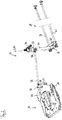
- FIG. 1 For example, an embodiment of the steering apparatus of the present application according to the present invention is indicated generally at 10. It is arranged on a semitrailer 12 partially shown.
- the steering device 10 has a semitrailer assembly 14 at its longitudinal end projecting in the ready-to-operate state, which has a semi-trailer frame-fixed module housing 16 and a saddle-rotating plateau 18 accommodated therein. From the saddle rotary plateau 18 is a kingpin 20 along its longitudinal axis L20 from.
- the kingpin is at coupling of the semitrailer of FIG. 1 introduced to a towing vehicle in a conventional manner in the fifth wheel of the towing vehicle and locked there.
- the saddle rotating plateau 18 is rotatably received in the assembly housing 16 about the longitudinal axis L20 of the kingpin 20.
- the saddle rotary platform 18 on its side facing the fifth wheel in operation, ie on the side from which also projects the kingpin 20, a rotary connecting wedge 22, which in the coupled state of the steering device 10 positively into the catch mouth of Fifth wheel engages and thus the saddle rotating platform 18 coupled for common rotation with the fifth wheel relative to the module housing 16.
- the relative rotation of the saddle rotating platform 18 relative to the module housing 16 the Relativgierwinkel between towing vehicle and semi-trailer.
- transmission lever 24 is pivotally mounted about a longitudinal axis L20 of the kingpin 20 parallel to the module housing solid transmission axis of rotation L24 (see also FIG. 2 ).
- a pivot lever axis L26 of a two-armed coupling pivot lever 26 is provided at an even greater distance than the transmission axis of rotation L24.
- the virtual plane E also contains the transmission rotational axis L24.
- the coupling rod 36 preferably penetrates the virtual plane E in the region 37 of the distance center of the distance between the transmission rotational axis L24 and the pivot lever axis L26.
- This distance central region 37 extends symmetrically about the distance center in each case 10% of the total distance of the axes L24 and L26 from each other on both sides of the distance center.
- the virtual plane in straight-ahead position cuts the coupling rod 36 approximately in its longitudinal center.
- a coupling rod 30 is arranged on the coupling pivot lever 26, which has an input lever 32 at a distance from the coupling pivot lever 26.
- the gooseneck rod 30 is pivotable together with the coupling pivot lever 26 and the input lever 32 about the longitudinal axis L20 of the kingpin 20 parallel pivot lever axis L26, which is also the longitudinal center axis of the gooseneck 30.
- semitrailer frame fixed brackets 34 are shown for pivotally mounting the gooseneck 30 on the semitrailer frame.
- the transmission lever 24 is connected by means of a coupling rod 36 with a remote from the gooseneck 36 end portion of the input lever 32.
- the connection of the coupling rod 36 is articulated at its two coupling points 71 and 74.
- the coupling rod 36 in the first embodiment the only transmission means, which transmits a movement from the transmission lever 24 and from the saddle rotating platform 18 to the coupling pivot lever 26.
- the rotational movement of the coupling pivot lever 26 is transmitted for each vehicle side with a separate switching rod 38 and 40 to the steering levers 42 and 60 in order to achieve the most accurate steering with the smallest possible rod cross-sections.
- the aforementioned switching linkage 28 includes two parallel in this example switching rods 38 and 40, which each lead from a longitudinal end of the coupling pivot lever 26 to a respective longitudinal end of a pivotally mounted on the semitrailer frame steering lever 42.
- the steering lever 42 is pivotable about its steering axis L42 as a pivot axis, which is located in the straight-ahead position of the steering device 10 between the two Anlenkorten the exchange rods 38 and 40 on the steering lever 42.
- the steering axis L42 is parallel to the longitudinal axis L20 of the coupling pin 20th
- the wheel 48 is in its area closer to the footprint due to the in FIG. 1 shown handlebar 50 hinged to the semitrailer frame.
- An even further from the kingpin 20 located further vehicle axle 52 may be coupled by another switching linkage 54 with the exchange rods 56 and 58 by means of another steering lever 60 and tie rods 62 to the steering lever 42.
- Another switching linkage 54 with the exchange rods 56 and 58 by means of another steering lever 60 and tie rods 62 to the steering lever 42.
- the transmission ratio does not decrease approximately linearly with the Relativgierwinkel between towing vehicle and semi-trailer 12, but the transmission ratio decreases non-linearly.
- the transmission ratio is smaller the faster, the greater the relative yaw angle between towing vehicle and semitrailer 12 is.
- the transmission ratio is understood as the change in the rotational angle position of the transmission lever 24 about its transmission axis L24 in relation to the change causing this change in the rotational position of the saddle rotating plateau 18 relative to the housing assembly 16 about the longitudinal axis L20 of the kingpin.
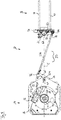
- FIG. 3 is a plan view of the trailer assembly 14 of the steering device 10 in the straight ahead position shown.
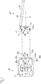
- FIG. 4 the same view is shown at a relative yaw angle ⁇ of 60 ° between traction vehicle and trailing vehicle. Accordingly, in FIG. 4 the saddle rotating plateau 18 relative to the in FIG. 3 shown rotated position by 60 °.
- the transmission lever 24 is pivotally connected to an auxiliary frame 64 about its transmission axis L24.
- the subframe 64 is rigidly connected to the package housing 16.
- the transmission lever 24 has two lever arms 66 and 68, each extending from the transmission axis of rotation L24 in different directions.
- the coupled to the saddle slewing platform 18 arm 66 of the transmission lever 24 has on its the Siltelcardau 18 side facing a dashed line groove 69, in which one of the saddle slewing platform 18 to the transmission lever 24 protruding projection 70 engages in the manner of a slotted guide.
- the touch area in which the protrusion 70 contacts at least one flank of the groove 68 is a plateau coupling point 71 at which the saddle rotary plateau 18 is coupled for common movement with the arm 68 of the transmission lever 24.
- the projection 70 pivots in the event of a rotational movement of the saddle plate 18 not only the arm 66 of the transmission lever 24, but also slides along the same, whereby the distance of the projection 70 from the transmission axis L24 with change in the rotational position of the saddle plate 18 also changes.
- the projection 70 is located only in the straight-ahead position on the flanks of the groove 69 that a rotational movement of the saddle rotary plateau 18 from the straight-ahead position out at the first moment orthogonal to the flank of the groove 69 and thus without slippage.
- the other arm 68 of the transmission lever 24 has at its location remote from the transmission axis L24 location the lever coupling point 72 with the coupling rod 36.
- a connecting line G2 of the lever coupling point 72 with the transmission rotational axis L24 and a connecting line G1 of the plateau coupling point 71 with the transmission rotational axis L24 enclose an angle of about 110 °.
- the longitudinal axis L36 of the coupling rod 36 is preferably orthogonal to the virtual connecting straight line in the straight-ahead position G2 between the transmission rotational axis L24 and the coupling point 72 as well as orthogonal to the virtual straight line G3, which connects the pivot lever axis L26 with the coupling point 74 of the coupling rod 36 with the input lever 32.
- FIG. 5 shows in the same perspective as FIG. 3 A second embodiment of a steering device according to the invention.
- the second embodiment of the FIG. 5 in which identical and functionally identical components and component sections are provided with the same reference numerals as in the first embodiment, but increased by the number 100, will be described below only insofar as it differs from the first embodiment.
- the coupling linkage is formed by two mutually parallel coupling rods 136a and 136b. Consequently, the transmission lever 124 is formed on both sides of the transmission axis of rotation L124 and has two lever arms 168a and 168b.
- the same lower case letters behind the reference numbers indicate a relationship of the so-called components. Consequently, the lever arm 168a is connected to the coupling rod 136a at the lever coupling point 172a. The same applies to the corresponding components with lowercase letters b.
- the coupling rods 136a and 136b extend parallel to the virtual plane E, and in each case at the same distance from the latter.
- the input lever 132 is formed as a two-armed lever because of the two existing coupling rods 136a and 136b, wherein the pivot lever axis L126 extends between the two arms of the input lever 132, again equidistant.
- the coupling pivot lever 126 has a one-armed design and projects on one side from the pivot lever axis L126.
- the component assembly comprising input lever, gooseneck and coupling pivot lever thus preferably always has the gooseneck, a one-armed lever and a two-armed lever.
- the coupling pivoting lever 126 in the second embodiment is therefore designed with one arm, because the switching linkage 128 has only exactly one switching rod 138, the coupling pivoting lever 126 with a in FIG. 5 not shown steering lever connects. Also, the input side of the steering lever may therefore be formed in one arm compared to the first embodiment.
- the connecting rod 138 penetrates in its course between the coupling pivot lever 126 and the steering lever, the virtual plane E, and preferably in an area around the distance center between the pivot lever axis L126 and steering axis, the area containing the distance center and starting from this not more than 10% of Total distance between said axes extends to the two axes out.
- the single exchange bar 138 is formed in the example shown by a rod with square hollow section with rectangular cross-section, so that they can be short in the direction of the pivot lever axis L126 and the steering axis, but orthogonal thereto wide and thus has sufficient rigidity for transmitting the necessary steering forces as a flat profile.
Landscapes
- Engineering & Computer Science (AREA)
- Chemical & Material Sciences (AREA)
- Combustion & Propulsion (AREA)
- Transportation (AREA)
- Mechanical Engineering (AREA)
- Steering Control In Accordance With Driving Conditions (AREA)
Priority Applications (1)
| Application Number | Priority Date | Filing Date | Title |
|---|---|---|---|
| EP18167593.5A EP3366550A1 (fr) | 2016-09-01 | 2017-08-28 | Dispositif de direction mécanique permettant le guidage forcé des suspensions indépendantes de véhicules utilitaires sur les remorques en fonction de l'angle de lacet relatif entre le véhicule tracteur et le véhicule tracté |
Applications Claiming Priority (1)
| Application Number | Priority Date | Filing Date | Title |
|---|---|---|---|
| DE102016216591.7A DE102016216591A1 (de) | 2016-09-01 | 2016-09-01 | Mechanische Lenkvorrichtung zur Zwangslenkung von Nutzfahrzeug-Einzelradaufhängungen an Sattelaufliegern abhängig vom Relativgierwinkel zwischen Zugfahrzeug und Nachlauffahrzeug |
Related Child Applications (2)
| Application Number | Title | Priority Date | Filing Date |
|---|---|---|---|
| EP18167593.5A Division-Into EP3366550A1 (fr) | 2016-09-01 | 2017-08-28 | Dispositif de direction mécanique permettant le guidage forcé des suspensions indépendantes de véhicules utilitaires sur les remorques en fonction de l'angle de lacet relatif entre le véhicule tracteur et le véhicule tracté |
| EP18167593.5A Division EP3366550A1 (fr) | 2016-09-01 | 2017-08-28 | Dispositif de direction mécanique permettant le guidage forcé des suspensions indépendantes de véhicules utilitaires sur les remorques en fonction de l'angle de lacet relatif entre le véhicule tracteur et le véhicule tracté |
Publications (3)
| Publication Number | Publication Date |
|---|---|
| EP3290300A1 true EP3290300A1 (fr) | 2018-03-07 |
| EP3290300B1 EP3290300B1 (fr) | 2019-10-02 |
| EP3290300B8 EP3290300B8 (fr) | 2019-11-13 |
Family
ID=59713923
Family Applications (2)
| Application Number | Title | Priority Date | Filing Date |
|---|---|---|---|
| EP18167593.5A Withdrawn EP3366550A1 (fr) | 2016-09-01 | 2017-08-28 | Dispositif de direction mécanique permettant le guidage forcé des suspensions indépendantes de véhicules utilitaires sur les remorques en fonction de l'angle de lacet relatif entre le véhicule tracteur et le véhicule tracté |
| EP17188091.7A Active EP3290300B8 (fr) | 2016-09-01 | 2017-08-28 | Dispositif de direction mécanique permettant le guidage forcé des suspensions indépendantes de véhicules utilitaires sur les remorques en fonction de l'angle de lacet relatif entre le véhicule tracteur et le véhicule tracté |
Family Applications Before (1)
| Application Number | Title | Priority Date | Filing Date |
|---|---|---|---|
| EP18167593.5A Withdrawn EP3366550A1 (fr) | 2016-09-01 | 2017-08-28 | Dispositif de direction mécanique permettant le guidage forcé des suspensions indépendantes de véhicules utilitaires sur les remorques en fonction de l'angle de lacet relatif entre le véhicule tracteur et le véhicule tracté |
Country Status (2)
| Country | Link |
|---|---|
| EP (2) | EP3366550A1 (fr) |
| DE (1) | DE102016216591A1 (fr) |
Families Citing this family (1)
| Publication number | Priority date | Publication date | Assignee | Title |
|---|---|---|---|---|
| DE102019204442A1 (de) * | 2019-03-29 | 2020-10-01 | Goldhofer Ag | Schwerlastfahrzeug |
Citations (5)
| Publication number | Priority date | Publication date | Assignee | Title |
|---|---|---|---|---|
| DE1630625A1 (de) * | 1967-08-24 | 1971-06-09 | Kaessbohrer Fahrzeug Karl | Radlenksystem fuer den Auflieger eines Zugwagens |
| EP0100351B1 (fr) * | 1982-02-10 | 1986-11-26 | National Research Development Corporation | Ameliorations relatives a des mecanismes de direction de vehicules |
| EP0320383A1 (fr) * | 1987-12-10 | 1989-06-14 | A.C.T.M. | Perfectionnements aux dispositifs utilisant un bissel pour le renforcement de la capacité de chargement de véhicules tracteurs |
| WO1995034435A1 (fr) * | 1994-06-16 | 1995-12-21 | Lohr Industrie | Liaison a correcteur angulaire entre deux modules routiers relies entre eux par un module intermeidiare autoporte |
| DE10317812A1 (de) * | 2003-04-16 | 2005-01-27 | Claas Saulgau Gmbh | Fahrwerkslenkung für eine landwirtschaftliche Arbeitsmaschine |
-
2016
- 2016-09-01 DE DE102016216591.7A patent/DE102016216591A1/de not_active Withdrawn
-
2017
- 2017-08-28 EP EP18167593.5A patent/EP3366550A1/fr not_active Withdrawn
- 2017-08-28 EP EP17188091.7A patent/EP3290300B8/fr active Active
Patent Citations (5)
| Publication number | Priority date | Publication date | Assignee | Title |
|---|---|---|---|---|
| DE1630625A1 (de) * | 1967-08-24 | 1971-06-09 | Kaessbohrer Fahrzeug Karl | Radlenksystem fuer den Auflieger eines Zugwagens |
| EP0100351B1 (fr) * | 1982-02-10 | 1986-11-26 | National Research Development Corporation | Ameliorations relatives a des mecanismes de direction de vehicules |
| EP0320383A1 (fr) * | 1987-12-10 | 1989-06-14 | A.C.T.M. | Perfectionnements aux dispositifs utilisant un bissel pour le renforcement de la capacité de chargement de véhicules tracteurs |
| WO1995034435A1 (fr) * | 1994-06-16 | 1995-12-21 | Lohr Industrie | Liaison a correcteur angulaire entre deux modules routiers relies entre eux par un module intermeidiare autoporte |
| DE10317812A1 (de) * | 2003-04-16 | 2005-01-27 | Claas Saulgau Gmbh | Fahrwerkslenkung für eine landwirtschaftliche Arbeitsmaschine |
Also Published As
| Publication number | Publication date |
|---|---|
| DE102016216591A1 (de) | 2018-03-01 |
| EP3290300B8 (fr) | 2019-11-13 |
| EP3290300B1 (fr) | 2019-10-02 |
| EP3366550A1 (fr) | 2018-08-29 |
Similar Documents
| Publication | Publication Date | Title |
|---|---|---|
| DE602004002248T2 (de) | Fahrzeuglenksystem | |
| DE3714688C2 (fr) | ||
| EP2242676B1 (fr) | Disposition d' un système de stabilisation du roulis ainsi que d' un système de direction sur un véhicule | |
| DE202021103914U1 (de) | Lenkungsanordnung mit verschiebbarer mittlerer Verbindung | |
| DE1755368A1 (de) | Hydraulische Zwangslenkung fuer gezogene Fahrzeuge | |
| EP0122956A1 (fr) | Dispositif pour la stabilité de marche des trains routiers avec couplage de traction de cinquième roue et pour des véhicules articulés | |
| EP1466813B1 (fr) | Axe de dolly avec train de roues orientables | |
| EP3299260A1 (fr) | Semi-remorque | |
| EP3290300B1 (fr) | Dispositif de direction mécanique permettant le guidage forcé des suspensions indépendantes de véhicules utilitaires sur les remorques en fonction de l'angle de lacet relatif entre le véhicule tracteur et le véhicule tracté | |
| DE2721975A1 (de) | Fahrzeugkupplung | |
| EP0033873B1 (fr) | Train routier à intervalle variable entre tracteur et remorque | |
| DE602005001095T2 (de) | Traktoraufhängung | |
| DE202011108878U1 (de) | Hinterachslenkvorrichtung für Anhängefahrzeuge, insbesondere für Schneidwerkswagen | |
| EP1972525B1 (fr) | Barres de direction de véhicule automobile | |
| EP2343229B1 (fr) | Essieu directeur | |
| DE112023000136T5 (de) | Struktur zum fahren eines vierrädrigen fahrzeugs in mehrere richtungen und zum dessen lenken | |
| DE202009016346U1 (de) | Hinterachslenkvorrichtung für drehschemelgelenkte Anhängefahrzeuge, insbesondere für Schneidwerkswagen | |
| DE4137382C1 (en) | Utility site-work vehicle - is articulated with fixed wheels on front carriage and steering wheels on rear carriage. | |
| DE2456165C3 (de) | Lenkvorrichtung für Gelenkwagenzüge | |
| EP0031596B1 (fr) | Direction avant pour remorques | |
| DE3328123A1 (de) | Lastzug mit einer lenkung fuer das anhaengerfahrzeug | |
| DE3707700A1 (de) | Mehrachslenkanlage | |
| DE102015224599A1 (de) | Nutzfahrzeug, insbesondere Schwerlastfahrzeug | |
| DE202015104832U1 (de) | Anhängefahrzeug | |
| DE102016102318A1 (de) | Lastaufnehmender vierrädriger Anhänger für einen Schleppzug |
Legal Events
| Date | Code | Title | Description |
|---|---|---|---|
| PUAI | Public reference made under article 153(3) epc to a published international application that has entered the european phase |
Free format text: ORIGINAL CODE: 0009012 |
|
| STAA | Information on the status of an ep patent application or granted ep patent |
Free format text: STATUS: REQUEST FOR EXAMINATION WAS MADE |
|
| 17P | Request for examination filed |
Effective date: 20170828 |
|
| AK | Designated contracting states |
Kind code of ref document: A1 Designated state(s): AL AT BE BG CH CY CZ DE DK EE ES FI FR GB GR HR HU IE IS IT LI LT LU LV MC MK MT NL NO PL PT RO RS SE SI SK SM TR |
|
| AX | Request for extension of the european patent |
Extension state: BA ME |
|
| RBV | Designated contracting states (corrected) |
Designated state(s): AL AT BE BG CH CY CZ DE DK EE ES FI FR GB GR HR HU IE IS IT LI LT LU LV MC MK MT NL NO PL PT RO RS SE SI SK SM TR |
|
| GRAP | Despatch of communication of intention to grant a patent |
Free format text: ORIGINAL CODE: EPIDOSNIGR1 |
|
| STAA | Information on the status of an ep patent application or granted ep patent |
Free format text: STATUS: GRANT OF PATENT IS INTENDED |
|
| INTG | Intention to grant announced |
Effective date: 20190417 |
|
| GRAS | Grant fee paid |
Free format text: ORIGINAL CODE: EPIDOSNIGR3 |
|
| GRAA | (expected) grant |
Free format text: ORIGINAL CODE: 0009210 |
|
| STAA | Information on the status of an ep patent application or granted ep patent |
Free format text: STATUS: THE PATENT HAS BEEN GRANTED |
|
| AK | Designated contracting states |
Kind code of ref document: B1 Designated state(s): AL AT BE BG CH CY CZ DE DK EE ES FI FR GB GR HR HU IE IS IT LI LT LU LV MC MK MT NL NO PL PT RO RS SE SI SK SM TR |
|
| REG | Reference to a national code |
Ref country code: GB Ref legal event code: FG4D Free format text: NOT ENGLISH |
|
| REG | Reference to a national code |
Ref country code: AT Ref legal event code: REF Ref document number: 1185870 Country of ref document: AT Kind code of ref document: T Effective date: 20191015 Ref country code: CH Ref legal event code: EP |
|
| REG | Reference to a national code |
Ref country code: DE Ref legal event code: R096 Ref document number: 502017002446 Country of ref document: DE |
|
| RAP2 | Party data changed (patent owner data changed or rights of a patent transferred) |
Owner name: TRIDEC BV |
|
| REG | Reference to a national code |
Ref country code: IE Ref legal event code: FG4D Free format text: LANGUAGE OF EP DOCUMENT: GERMAN |
|
| REG | Reference to a national code |
Ref country code: CH Ref legal event code: PK Free format text: BERICHTIGUNG B8 |
|
| REG | Reference to a national code |
Ref country code: NL Ref legal event code: FP |
|
| REG | Reference to a national code |
Ref country code: LT Ref legal event code: MG4D |
|
| PG25 | Lapsed in a contracting state [announced via postgrant information from national office to epo] |
Ref country code: GR Free format text: LAPSE BECAUSE OF FAILURE TO SUBMIT A TRANSLATION OF THE DESCRIPTION OR TO PAY THE FEE WITHIN THE PRESCRIBED TIME-LIMIT Effective date: 20200103 Ref country code: LT Free format text: LAPSE BECAUSE OF FAILURE TO SUBMIT A TRANSLATION OF THE DESCRIPTION OR TO PAY THE FEE WITHIN THE PRESCRIBED TIME-LIMIT Effective date: 20191002 Ref country code: PL Free format text: LAPSE BECAUSE OF FAILURE TO SUBMIT A TRANSLATION OF THE DESCRIPTION OR TO PAY THE FEE WITHIN THE PRESCRIBED TIME-LIMIT Effective date: 20191002 Ref country code: PT Free format text: LAPSE BECAUSE OF FAILURE TO SUBMIT A TRANSLATION OF THE DESCRIPTION OR TO PAY THE FEE WITHIN THE PRESCRIBED TIME-LIMIT Effective date: 20200203 Ref country code: BG Free format text: LAPSE BECAUSE OF FAILURE TO SUBMIT A TRANSLATION OF THE DESCRIPTION OR TO PAY THE FEE WITHIN THE PRESCRIBED TIME-LIMIT Effective date: 20200102 Ref country code: FI Free format text: LAPSE BECAUSE OF FAILURE TO SUBMIT A TRANSLATION OF THE DESCRIPTION OR TO PAY THE FEE WITHIN THE PRESCRIBED TIME-LIMIT Effective date: 20191002 Ref country code: NO Free format text: LAPSE BECAUSE OF FAILURE TO SUBMIT A TRANSLATION OF THE DESCRIPTION OR TO PAY THE FEE WITHIN THE PRESCRIBED TIME-LIMIT Effective date: 20200102 Ref country code: LV Free format text: LAPSE BECAUSE OF FAILURE TO SUBMIT A TRANSLATION OF THE DESCRIPTION OR TO PAY THE FEE WITHIN THE PRESCRIBED TIME-LIMIT Effective date: 20191002 Ref country code: SE Free format text: LAPSE BECAUSE OF FAILURE TO SUBMIT A TRANSLATION OF THE DESCRIPTION OR TO PAY THE FEE WITHIN THE PRESCRIBED TIME-LIMIT Effective date: 20191002 Ref country code: ES Free format text: LAPSE BECAUSE OF FAILURE TO SUBMIT A TRANSLATION OF THE DESCRIPTION OR TO PAY THE FEE WITHIN THE PRESCRIBED TIME-LIMIT Effective date: 20191002 |
|
| PG25 | Lapsed in a contracting state [announced via postgrant information from national office to epo] |
Ref country code: CZ Free format text: LAPSE BECAUSE OF FAILURE TO SUBMIT A TRANSLATION OF THE DESCRIPTION OR TO PAY THE FEE WITHIN THE PRESCRIBED TIME-LIMIT Effective date: 20191002 Ref country code: RS Free format text: LAPSE BECAUSE OF FAILURE TO SUBMIT A TRANSLATION OF THE DESCRIPTION OR TO PAY THE FEE WITHIN THE PRESCRIBED TIME-LIMIT Effective date: 20191002 Ref country code: IS Free format text: LAPSE BECAUSE OF FAILURE TO SUBMIT A TRANSLATION OF THE DESCRIPTION OR TO PAY THE FEE WITHIN THE PRESCRIBED TIME-LIMIT Effective date: 20200224 Ref country code: HR Free format text: LAPSE BECAUSE OF FAILURE TO SUBMIT A TRANSLATION OF THE DESCRIPTION OR TO PAY THE FEE WITHIN THE PRESCRIBED TIME-LIMIT Effective date: 20191002 |
|
| PG25 | Lapsed in a contracting state [announced via postgrant information from national office to epo] |
Ref country code: AL Free format text: LAPSE BECAUSE OF FAILURE TO SUBMIT A TRANSLATION OF THE DESCRIPTION OR TO PAY THE FEE WITHIN THE PRESCRIBED TIME-LIMIT Effective date: 20191002 |
|
| REG | Reference to a national code |
Ref country code: DE Ref legal event code: R097 Ref document number: 502017002446 Country of ref document: DE |
|
| PG2D | Information on lapse in contracting state deleted |
Ref country code: IS |
|
| PG25 | Lapsed in a contracting state [announced via postgrant information from national office to epo] |
Ref country code: IS Free format text: LAPSE BECAUSE OF FAILURE TO SUBMIT A TRANSLATION OF THE DESCRIPTION OR TO PAY THE FEE WITHIN THE PRESCRIBED TIME-LIMIT Effective date: 20200202 Ref country code: EE Free format text: LAPSE BECAUSE OF FAILURE TO SUBMIT A TRANSLATION OF THE DESCRIPTION OR TO PAY THE FEE WITHIN THE PRESCRIBED TIME-LIMIT Effective date: 20191002 Ref country code: DK Free format text: LAPSE BECAUSE OF FAILURE TO SUBMIT A TRANSLATION OF THE DESCRIPTION OR TO PAY THE FEE WITHIN THE PRESCRIBED TIME-LIMIT Effective date: 20191002 Ref country code: RO Free format text: LAPSE BECAUSE OF FAILURE TO SUBMIT A TRANSLATION OF THE DESCRIPTION OR TO PAY THE FEE WITHIN THE PRESCRIBED TIME-LIMIT Effective date: 20191002 |
|
| PLBE | No opposition filed within time limit |
Free format text: ORIGINAL CODE: 0009261 |
|
| STAA | Information on the status of an ep patent application or granted ep patent |
Free format text: STATUS: NO OPPOSITION FILED WITHIN TIME LIMIT |
|
| PG25 | Lapsed in a contracting state [announced via postgrant information from national office to epo] |
Ref country code: SK Free format text: LAPSE BECAUSE OF FAILURE TO SUBMIT A TRANSLATION OF THE DESCRIPTION OR TO PAY THE FEE WITHIN THE PRESCRIBED TIME-LIMIT Effective date: 20191002 Ref country code: IT Free format text: LAPSE BECAUSE OF FAILURE TO SUBMIT A TRANSLATION OF THE DESCRIPTION OR TO PAY THE FEE WITHIN THE PRESCRIBED TIME-LIMIT Effective date: 20191002 Ref country code: SM Free format text: LAPSE BECAUSE OF FAILURE TO SUBMIT A TRANSLATION OF THE DESCRIPTION OR TO PAY THE FEE WITHIN THE PRESCRIBED TIME-LIMIT Effective date: 20191002 |
|
| 26N | No opposition filed |
Effective date: 20200703 |
|
| PG25 | Lapsed in a contracting state [announced via postgrant information from national office to epo] |
Ref country code: SI Free format text: LAPSE BECAUSE OF FAILURE TO SUBMIT A TRANSLATION OF THE DESCRIPTION OR TO PAY THE FEE WITHIN THE PRESCRIBED TIME-LIMIT Effective date: 20191002 |
|
| PG25 | Lapsed in a contracting state [announced via postgrant information from national office to epo] |
Ref country code: MC Free format text: LAPSE BECAUSE OF FAILURE TO SUBMIT A TRANSLATION OF THE DESCRIPTION OR TO PAY THE FEE WITHIN THE PRESCRIBED TIME-LIMIT Effective date: 20191002 |
|
| REG | Reference to a national code |
Ref country code: CH Ref legal event code: PL |
|
| PG25 | Lapsed in a contracting state [announced via postgrant information from national office to epo] |
Ref country code: CH Free format text: LAPSE BECAUSE OF NON-PAYMENT OF DUE FEES Effective date: 20200831 Ref country code: LI Free format text: LAPSE BECAUSE OF NON-PAYMENT OF DUE FEES Effective date: 20200831 Ref country code: LU Free format text: LAPSE BECAUSE OF NON-PAYMENT OF DUE FEES Effective date: 20200828 |
|
| REG | Reference to a national code |
Ref country code: BE Ref legal event code: MM Effective date: 20200831 |
|
| PG25 | Lapsed in a contracting state [announced via postgrant information from national office to epo] |
Ref country code: FR Free format text: LAPSE BECAUSE OF NON-PAYMENT OF DUE FEES Effective date: 20200831 |
|
| PG25 | Lapsed in a contracting state [announced via postgrant information from national office to epo] |
Ref country code: BE Free format text: LAPSE BECAUSE OF NON-PAYMENT OF DUE FEES Effective date: 20200831 Ref country code: IE Free format text: LAPSE BECAUSE OF NON-PAYMENT OF DUE FEES Effective date: 20200828 |
|
| PG25 | Lapsed in a contracting state [announced via postgrant information from national office to epo] |
Ref country code: TR Free format text: LAPSE BECAUSE OF FAILURE TO SUBMIT A TRANSLATION OF THE DESCRIPTION OR TO PAY THE FEE WITHIN THE PRESCRIBED TIME-LIMIT Effective date: 20191002 Ref country code: MT Free format text: LAPSE BECAUSE OF FAILURE TO SUBMIT A TRANSLATION OF THE DESCRIPTION OR TO PAY THE FEE WITHIN THE PRESCRIBED TIME-LIMIT Effective date: 20191002 Ref country code: CY Free format text: LAPSE BECAUSE OF FAILURE TO SUBMIT A TRANSLATION OF THE DESCRIPTION OR TO PAY THE FEE WITHIN THE PRESCRIBED TIME-LIMIT Effective date: 20191002 |
|
| PG25 | Lapsed in a contracting state [announced via postgrant information from national office to epo] |
Ref country code: MK Free format text: LAPSE BECAUSE OF FAILURE TO SUBMIT A TRANSLATION OF THE DESCRIPTION OR TO PAY THE FEE WITHIN THE PRESCRIBED TIME-LIMIT Effective date: 20191002 |
|
| REG | Reference to a national code |
Ref country code: AT Ref legal event code: MM01 Ref document number: 1185870 Country of ref document: AT Kind code of ref document: T Effective date: 20220828 |
|
| PG25 | Lapsed in a contracting state [announced via postgrant information from national office to epo] |
Ref country code: AT Free format text: LAPSE BECAUSE OF NON-PAYMENT OF DUE FEES Effective date: 20220828 |
|
| PGFP | Annual fee paid to national office [announced via postgrant information from national office to epo] |
Ref country code: NL Payment date: 20250826 Year of fee payment: 9 |
|
| PGFP | Annual fee paid to national office [announced via postgrant information from national office to epo] |
Ref country code: DE Payment date: 20250828 Year of fee payment: 9 |
|
| PGFP | Annual fee paid to national office [announced via postgrant information from national office to epo] |
Ref country code: GB Payment date: 20250827 Year of fee payment: 9 |