EP3290623B1 - Dispositif de verrouillage - Google Patents
Dispositif de verrouillage Download PDFInfo
- Publication number
- EP3290623B1 EP3290623B1 EP17183411.2A EP17183411A EP3290623B1 EP 3290623 B1 EP3290623 B1 EP 3290623B1 EP 17183411 A EP17183411 A EP 17183411A EP 3290623 B1 EP3290623 B1 EP 3290623B1
- Authority
- EP
- European Patent Office
- Prior art keywords
- handle
- locking element
- main body
- clamping sleeve
- shank
- Prior art date
- Legal status (The legal status is an assumption and is not a legal conclusion. Google has not performed a legal analysis and makes no representation as to the accuracy of the status listed.)
- Active
Links
Images


Classifications
-
- E—FIXED CONSTRUCTIONS
- E05—LOCKS; KEYS; WINDOW OR DOOR FITTINGS; SAFES
- E05B—LOCKS; ACCESSORIES THEREFOR; HANDCUFFS
- E05B83/00—Vehicle locks specially adapted for particular types of wing or vehicle
- E05B83/36—Locks for passenger or like doors
- E05B83/44—Locks for passenger or like doors for recreational vehicles, e.g. caravans or camper vans
-
- E—FIXED CONSTRUCTIONS
- E05—LOCKS; KEYS; WINDOW OR DOOR FITTINGS; SAFES
- E05B—LOCKS; ACCESSORIES THEREFOR; HANDCUFFS
- E05B13/00—Devices preventing the key or the handle or both from being used
- E05B13/10—Devices preventing the key or the handle or both from being used formed by a lock arranged in the handle
-
- E—FIXED CONSTRUCTIONS
- E05—LOCKS; KEYS; WINDOW OR DOOR FITTINGS; SAFES
- E05B—LOCKS; ACCESSORIES THEREFOR; HANDCUFFS
- E05B17/00—Accessories in connection with locks
- E05B17/0025—Devices for forcing the wing firmly against its seat or to initiate the opening of the wing
-
- E—FIXED CONSTRUCTIONS
- E05—LOCKS; KEYS; WINDOW OR DOOR FITTINGS; SAFES
- E05B—LOCKS; ACCESSORIES THEREFOR; HANDCUFFS
- E05B5/00—Handles completely let into the surface of the wing
- E05B5/003—Pop-out handles, e.g. sliding outwardly before rotation
-
- E—FIXED CONSTRUCTIONS
- E05—LOCKS; KEYS; WINDOW OR DOOR FITTINGS; SAFES
- E05B—LOCKS; ACCESSORIES THEREFOR; HANDCUFFS
- E05B85/00—Details of vehicle locks not provided for in groups E05B77/00 - E05B83/00
- E05B85/10—Handles
- E05B85/107—Pop-out handles, e.g. sliding outwardly before rotation
-
- E—FIXED CONSTRUCTIONS
- E05—LOCKS; KEYS; WINDOW OR DOOR FITTINGS; SAFES
- E05C—BOLTS OR FASTENING DEVICES FOR WINGS, SPECIALLY FOR DOORS OR WINDOWS
- E05C5/00—Fastening devices with bolts moving otherwise than only rectilinearly and only pivotally or rotatively
Definitions
- the present invention relates to a safe locking device, intended for closing and opening doors, especially of caravans or other recreational vehicles.
- a known type of safe lock for caravan doors comprises an internal cylinder operable by a key, a handle located on the external side of the door and a lever located on the internal side, perpendicular to the axis of the lock.
- the lever In the locked configuration, the lever is oriented so as to be superimposed with the edge of a wall of the caravan on which the door abuts, at a free vertical edge thereof.
- the lever presses against the edge of the wall and the handle is in a retracted position in which it is adjacent to the door and cannot be rotated.
- the user turns the handle through ninety degrees in a first direction, causing the axial extension of the lever towards the inside of the caravan.
- the user performs a first rotation through ninety degrees of the handle, in the opposite direction to the mentioned first direction, which returns the lever until it faces the edge of the wall of the caravan and then performs a second rotation through ninety degrees, proceeding in the same direction.
- US20090256368 discloses a recessed compression latch, intended to be used in cabinets or panel doors and including a housing having a cavity for receiving a handle, the latter being connected via a pin to a movable shaft, which passes through the housing and is provided with a cam.
- EP2106488 describes a safety closure for doors or hatches disposed on a vehicle, comprising a closure housing attached to a part that is fixed to the vehicle.
- a locking shaft carrying a locking tongue on its free end is rotatable by means of an operating handle between a closed position and an open position for the door or hatch.
- the locking shaft is rotatable between an open position and a closed position and the operating handle is movable relative to the locking shaft and axially displaceable between an retracted locked position and an operating position, where it protrudes from the housing.
- the technical task underpinning the present invention is therefore to propose a locking device that overcomes the limits of the prior art, allowing the door to be locked more easily, quickly and intuitively.
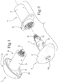
- reference numeral 1 indicates a locking device according to the invention.
- the device 1 proposed is especially, but not exclusively, designed for use in safe locks of doors of caravans or other recreational vehicles.
- the device 1 according to the invention includes first of all a main body 10 that is fixable to the door of the caravan.
- the main body 10 can be assembled in the door, so as to cross it from one side to the other.
- the main body 10 is preferably tubular, elongated and substantially axisymmetric; in the example illustrated, it comprises a cylindrical muff 11, equipped with a cavity in which, as will be explained below, different components of the invention are acting.
- the main body 10 is the supporting element of the invention that anchors the device 1 to the door and constitutes a fixed reference for the movements of the other components.
- the main body 10 is assembled at or near to the free vertical edge of the door, opposite the one provided with hinges.
- the device 1 can act on one edge of a wall of the caravan that laterally defines the access compartment to the caravan that is opened or locked by the door.
- the device 1 then comprises a rotatable handle 2 relative to said main body 10 and sliding axially thereto.
- the handle 2 can comprise a knob 21, for example elongated, from the centre of which a shank 22 projects, for example cylindrical, inserted in the main body 10.
- the knob 21, in use, is positioned at the external side of the door to which the device 1 is applied.
- the handle 2 can be generally T-shaped.
- the invention also envisages a cylinder for locks, of the type that can be operated through a key, coupled to the handle 2; the cylinder is not shown as it can be of the known type.
- the cylinder is contained in the handle 2 itself, inserted axially therein, for example in an internal cavity 210.
- the cylinder is adapted to lock / unlock the movement of the handle 2, according to modalities detailed below.
- the handle 2 is axially slidable from a retracted safe position to an extended use position.
- the knob 21 of the handle 2 can abut against the main body 10 and possibly against the door; in the use position, the knob 21 projects from the door so as to be able to be easily gripped by the user.
- the locking element 31, 32 is axially slidable, relative to the main body 10, between said intermediate position and a locked position, according to modalities specified in detail below.
- the intermediate position of the locking element 31, 32 is an extended position, in the axial direction, while the locked position is a retracted position.
- the locking element 31, 32 can comprise a locking lever 32, substantially transversal to the axis of the device 1 (or to the axis of the main body 10), and a coupling member 31 of the lever inserted in the main body 10.
- the lever 32 projects transversally and laterally to the coupling member 31.
- the lever 32 is arranged at the internal side of the door.
- the coupling member 31 can be a substantially cylindrical block, which has an external threaded end to which the lever 32 is coupled, the latter being able to have an S (or Z) shaped profile.
- the lever 32 In the locked position, the lever 32 abuts against the mentioned edge of the wall of the caravan, alongside the access compartment, so as to press it and define the locking between the door and the wall itself.
- shank 22 of the handle 2 and the members 32 of the locking element are aligned and are substantially coaxial to the main body 10.
- an elastic contrast means 4 is provided interposed between the handle 2 and the locking element 31, 32.
- the elastic means comprising for example a spiral spring 4, is interposed between the shank 22 of the handle 2 and the member 32 of the locking element, so as to urge them to mutual axial distancing (see figure 3 ).
- the device 1 includes a clamping element 5, housed in the main body 10, mechanically connected to the handle 2 and to the locking element 31, 32 and adapted to move the locking element 31, 32 from the intermediate position to the locked position, following a thrust exerted on the handle 2.
- the knob 21 of the handle 2 may comprise a cavity 211 facing towards the main body 10, i.e. towards the door; in this case, the main body 10 can be provided with a shaped plate 12, for example made as a single piece with the muff 11, adapted to be inserted in the cavity of the knob 21, when it is in the safe position.
- knob 21 is subject to a further constraint against rotary movements relative to the main body 10, which prevent at least in part any attempts to force the lock.
- the plate 12 can be screwed directly onto the door. The user inserts the key into the cylinder and unlocks the lock.
- the handle 2 is free to slide axially and to rotate with respect to the main body 10.
- the handle 2 After unlocking, the handle 2 translates in the use position, pushed by the elastic means and, at the same time, the locking element 31, 32 translates in the opposite direction, in an extended unlocking position that corresponds to the aforementioned intermediate position (see figure 9 ).
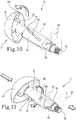
- the user turns the handle 2 in a first direction, for example through ninety degrees, so as to rotate the locking element 31, 32 in an open position, distanced from the intermediate one (see figure 10 ).
- the door can be opened and access to the caravan is allowed.
- the user does not need to make any double turns of the handle 2 to lock the door but only one turn to arrange the lever 32 in the pre-locking position and a simple push of the handle 2.
- the clamping element comprises a clamping sleeve 5, inserted in the main body 10 so as to be coaxial thereto (see in particular figure 3 ).
- the clamping sleeve 5 is rotatable in the main body 10 but is constrained against axial sliding.
- the clamping sleeve 5 is equipped with a first end into which the shank 22 of the handle 2 is inserted, with the possibility of axial sliding, and a second end, opposite the first one, into which the coupling member 31 of the locking element 31, 32 is inserted with the possibility of axial sliding.
- the clamping sleeve 5 comprises a first and a second longitudinal portion 51, 52, one being the continuation of the other.
- the first portion 51 of the sleeve ends with the first opening of the end into which the shank 22 of the handle 2 is inserted, while the second portion 52 ends with the second opening of the end where the coupling member 31 of the locking element 31, 32 is inserted.
- the second portion 52 has a smaller external diameter than that of the first portion 51, however this is not a mandatory aspect.
- a pair of guide slots 61, 62, 63, 64 is afforded.
- the lateral wall of the first portion 51 comprises a first pair of elongated through slots 61, 62, while the lateral wall of the second portion 52 comprises a second pair of elongated through slots 63, 64.
- the slots 61, 62 of the first portion 51 guide the reciprocal movements between the shank 22 and the sleeve 5 while the slots 63, 64 of the second portion 52 constrain reciprocal movements between the coupling member 31 and the sleeve 5.
- the slots 61, 62, 63, 64 may be arranged in diametrically opposite positions to the respective portion 51, 52 of the clamping sleeve 5 and be symmetrical with respect to an ideal plane that passes through the axis of the sleeve 5 itself.
- the slots 61, 62, 63, 64 may be oblique with respect to an ideal plane that passes through the axis of the clamping sleeve 5 and through the slots themselves.
- the slots 61, 62, 63, 64 of the first and of the second portion 51, 52 are consecutive two by two with respect to the longitudinal extension direction of the clamping sleeve 5.
- a slot 61, 62 of the first portion 51 has an opposite inclination direction to the consecutive slot 63, 64 afforded in the second portion 52.
- the slots 61, 62, 63, 64 of the clamping sleeve 5 can be rectilinear or curved, with different curvatures and variable lengths.
- the invention envisages at least a first slot 61, 62 afforded in the first longitudinal portion 51 of the sleeve 5, to which the shank 22 of the handle 2 is constrained, and at least a second slot 63, 64, afforded in the second portion 52 to which the coupling member 31 is constrained.
- the first pair of slots 61, 62 is crossed and slidably engaged by a pin 71 solidly connected to the shank 22 of the handle 2, while the second pair of slots 63, 64 is crossed and slidably engaged by a pin 72 solidly connected to the coupling member 31.
- the shank 22 and the coupling member 31 can be hollow and envisage respective through holes 220, 310 in which the related pin 71, 72 is inserted.
- each pin 71, 72 is slidably inserted into a respective rectilinear guide 13, 14, located internally to the main body 10 and preferably defined by a groove afforded on the internal surface of the muff 11 (see figures 4, 5 and 6 ).
- guides 13, 14 which may be placed opposite in the internal surface of the muff 11 of the main body 10 and have a longitudinal extension parallel to the axis of the muff 11 itself.
- each pin 71, 72 two opposite guides 13, 14 may be provided, whose length is proportional to that of the slots 61, 62, 63, 64 in which the related pins are inserted.
- the guides 13, 14 of the muff 11 have a transversal extension 131, 141, having the shape of an arc of a circle, in which the pins 71, 72 can slide once the handle 2 and the locking element 31, 32 are brought into the reciprocal extended position.
- This expedient allows the user to turn the locking lever 32 through the rotation of the knob 21 of the handle 2, through a certain angular stroke, preferably ninety degrees, bringing it for example into a vertical position (see figure 10 ).
- the shank 22 of the handle 2 and the coupling member 31 are rotationally connected to one another through the pins 71, 72 that engage the clamping sleeve 5 in the slots 61, 62, 63, 64.
- the thrust exerted on the handle 2 produces a translation of the pin 71 of the shank 22 in the direction of the door, which in turn produces a rotation of the clamping sleeve 5, due to the engagement between the pin 71 and the first pair of slots 61, 62 ( figure 11 ).
- the rotation of the clamping sleeve 5 causes the translation of the pin 72 of the coupling member 31 in the opposite direction to that of the handle 2, due to the inclinations of the second slots 63, 64.
- the slots 61, 62 of the first pair are longer than those of the second pair 63, 64 according to a ratio chosen so as to make sure that the thrust exerted on the knob 21 of the handle 2 is multiplied when it is translated into the clamping thrust exerted by the lever 32 on the edge of the caravan wall.
- the aforementioned cylinder which is solidly constrained to the handle 2, is adapted to be locked in a releasable way to the clamping sleeve 5 defining the locking and unlocking of the handle 2 in the device 1.
- the clamping sleeve 5 can be equipped with a shaped through hole 50, afforded at its lateral wall, in which, in the locked configuration, a shaped plug 8 is inserted, connected to the internal kinematic mechanisms of the cylinder.
- the handle 2 is unlocked, i.e. it is free to translate due to the action of the elastic means 4.
Landscapes
- Engineering & Computer Science (AREA)
- Mechanical Engineering (AREA)
- Lock And Its Accessories (AREA)
Claims (10)
- Dispositif de verrouillage (1) pour portes ou similaires, comprenant:un corps principal (10) pouvant être fixé à une porte;une poignée rotative (2) par rapport au dit corps principal (10) et coulissant axialement par rapport à celui-ci;un cylindre pour serrures couplé à la poignée (2) et adapté pour verrouiller/déverrouiller le mouvement de ladite poignée (2); etun élément de verrouillage (31, 32) pouvant être actionné en rotation au moyen de ladite poignée (2) entre une position d'ouverture et une position intermédiaire et pouvant coulisser axialement par rapport au corps principal (10) entre ladite position intermédiaire et une position de fermeture; etun élément de serrage (5) logé dans le corps principal (10), étant relié mécaniquement à la poignée (2) et à l'élément de verrouillage (31, 32) et capable de déplacer l'élément de verrouillage (31, 32) de la position intermédiaire à ladite position de fermeture suite à une poussée exercée sur la poignée (2);dans lequel l'élément de serrage comprend un manchon de serrage (5) comportant une première extrémité, dans laquelle est introduite une tige (22) étant capable de coulisser axialement, cette tige (22) étant comprise dans ladite poignée (2), et une seconde extrémité opposée, dans laquelle est introduite une partie (31) de l'élément de verrouillage, étant capable de coulisser axialement ;dans lequel ledit manchon de serrage (5) comprend une première partie longitudinale (51), incluant au moins une première fente de guidage (61, 62) à laquelle ladite tige (22) de la poignée (2) est solidement fixée, et une seconde partie longitudinale (52) comprenant au moins une seconde fente de guidage (63, 64) à laquelle ladite partie (31) de l'élément de verrouillage est solidement fixée;dans lequel lesdites fentes de guidage (61, 62, 63, 64) sont obliques par rapport à un plan idéal passant par l'axe du manchon (5), ladite première fente (61, 62) étant plus longue que ladite seconde fente (63, 64) et ayant également une direction d'inclinaison opposée à celle de la seconde fente (63, 64) par rapport à une direction de référence axiale.
- Dispositif (1) selon la revendication précédente, comprenant un moyen d'opposition élastique (4) interposé entre la poignée (2) et ledit élément de verrouillage (31, 32).
- Dispositif (1) selon au moins une des revendications précédentes, dans lequel la poignée (2) est adaptée pour se déplacer axialement d'une position rétractée de sécurité à une position d'utilisation étendue, ledit élément de serrage (5) étant capable de fixer solidement en rotation la poignée (2) à l'élément de verrouillage (31, 32) une fois que la poignée (2) se trouve dans la position d'utilisation et l'élément de verrouillage (31, 32) dans la position intermédiaire de celle-ci.
- Dispositif (1) selon au moins une des revendications précédentes, dans lequel l'élément de serrage (5) peut pivoter à l'intérieur du corps principal (10).
- Dispositif (1) selon au moins une des revendications précédentes, dans lequel ledit élément de serrage (5) est solidement fixé par rapport aux déplacements axiaux à l'intérieur du corps principal (10).
- Dispositif (1) selon la revendication 1, dans lequel le manchon de serrage (5) comprend une première paire de fentes de guidage (61, 62) pour la tige (22) de la poignée (2), les fentes de ladite première paire étant disposées dans des positions diamétralement opposées dans ladite première partie (51) du manchon de serrage (5) et étant symétriques par rapport à un plan idéal passant par ledit axe.
- Dispositif (1) selon la revendication 1, dans lequel le manchon de serrage (5) comprend une seconde paire de fentes de guidage (63, 64) pour ladite partie (31) de l'élément de verrouillage, les fentes de ladite seconde paire étant disposées dans des positions diamétralement opposées dans ladite seconde partie (52) du manchon de serrage (5) et étant symétriques par rapport à un plan idéal passant par ledit axe.
- Dispositif (1) selon la revendication 1, dans lequel chaque fente (61, 62, 63, 64) est traversée et limite le mouvement d'un ergot (71, 72) relié rigidement à la tige (22) ou à ladite première partie (31) de l'élément de verrouillage (31, 32).
- Dispositif (1) selon la revendication précédente, dans lequel chaque ergot (71, 72) est introduit de manière coulissante dans au moins un guide linéaire (13, 14) formé à l'intérieur du corps principal (10).
- Dispositif (1) selon la revendication précédente, dans lequel, à proximité d'au moins une extrémité, le guide linéaire (13, 14) présente une extension transversale (131, 141) dans laquelle ledit ergot (71, 72) peut coulisser.
Applications Claiming Priority (1)
| Application Number | Priority Date | Filing Date | Title |
|---|---|---|---|
| IT102016000076562A IT201600076562A1 (it) | 2016-09-02 | 2016-09-02 | Dispositivo di chiusura |
Publications (2)
| Publication Number | Publication Date |
|---|---|
| EP3290623A1 EP3290623A1 (fr) | 2018-03-07 |
| EP3290623B1 true EP3290623B1 (fr) | 2020-12-23 |
Family
ID=58455386
Family Applications (1)
| Application Number | Title | Priority Date | Filing Date |
|---|---|---|---|
| EP17183411.2A Active EP3290623B1 (fr) | 2016-09-02 | 2017-07-26 | Dispositif de verrouillage |
Country Status (2)
| Country | Link |
|---|---|
| EP (1) | EP3290623B1 (fr) |
| IT (1) | IT201600076562A1 (fr) |
Families Citing this family (6)
| Publication number | Priority date | Publication date | Assignee | Title |
|---|---|---|---|---|
| IT201900021624A1 (it) * | 2019-11-19 | 2021-05-19 | Daken S P A | Serratura con maniglia estraibile |
| CN111173367B (zh) * | 2020-01-21 | 2024-07-19 | 江苏三乔智能科技有限公司 | 一种把手可隐藏的门窗锁 |
| CN111719951B (zh) * | 2020-05-29 | 2024-01-05 | 宁波生久科技有限公司 | 一体式弹子锁芯把手面板锁 |
| KR102802868B1 (ko) * | 2020-08-26 | 2025-04-30 | 엘지전자 주식회사 | 도어핸들 |
| CN113040605B (zh) * | 2021-03-30 | 2024-11-26 | 珠海鑫润智能家电有限公司 | 咖啡机及其工作方法 |
| CN112869566B (zh) * | 2021-03-30 | 2024-12-20 | 珠海鑫润智能家电有限公司 | 咖啡机用锁紧机构及其工作方法 |
Family Cites Families (3)
| Publication number | Priority date | Publication date | Assignee | Title |
|---|---|---|---|---|
| US1907625A (en) * | 1930-03-24 | 1933-05-09 | Knape & Vogt Mfg Co | Showcase sliding doorlock |
| DE202007013514U1 (de) * | 2007-09-27 | 2007-12-06 | Emka Beschlagteile Gmbh & Co. Kg | Drehspannverschluss mit Betätigungsgriffsicherung |
| US20090256368A1 (en) * | 2008-04-09 | 2009-10-15 | Tam Thanh Le | Recessed compression latch |
-
2016
- 2016-09-02 IT IT102016000076562A patent/IT201600076562A1/it unknown
-
2017
- 2017-07-26 EP EP17183411.2A patent/EP3290623B1/fr active Active
Non-Patent Citations (1)
| Title |
|---|
| None * |
Also Published As
| Publication number | Publication date |
|---|---|
| EP3290623A1 (fr) | 2018-03-07 |
| IT201600076562A1 (it) | 2018-03-02 |
Similar Documents
| Publication | Publication Date | Title |
|---|---|---|
| EP3290623B1 (fr) | Dispositif de verrouillage | |
| US2322040A (en) | Handle and latch operating device | |
| CN112262246B (zh) | 用于操作锁的电驱动机构 | |
| EP3058154B1 (fr) | Poignée de porte | |
| US5862690A (en) | Low profile handle | |
| US7228719B2 (en) | Sliding door lock | |
| EP3408474B1 (fr) | Poignée pour assemblage universel | |
| EP2435648B1 (fr) | Dispositif pour verrouiller deux vantaux dans une configuration fermée | |
| KR20100129753A (ko) | 캠락 | |
| CN116498162B (zh) | 电子装置的上锁方法及电子装置锁 | |
| US9284749B2 (en) | Door lock assembly | |
| EP2529069A1 (fr) | Serrure à barillet pour porte | |
| CA3003898A1 (fr) | Serrure de surete | |
| KR20050036950A (ko) | 도어 록킹 메카니즘 | |
| US20060278505A1 (en) | Device for actuating an electric switching device with locking device | |
| EP3784855A1 (fr) | Serrure de véhicule automobile | |
| EP2662516B1 (fr) | Serrure anti-panique | |
| EP3408473B1 (fr) | Poignée multidirectionnelle | |
| US2642735A (en) | Key-in-knob lock | |
| US11066848B2 (en) | Push to lock and unlock door lock | |
| CA2795998C (fr) | Mecanisme de verrou de porte a acces multiples avec actionnement de came reversible | |
| KR20020023614A (ko) | 도어 잠금장치 | |
| KR0130503Y1 (ko) | 해정위치 구속형 래치장치 | |
| WO2009113949A1 (fr) | Serrure à pêne demi-tour | |
| JP5020855B2 (ja) | 車両用ハンドル装置 |
Legal Events
| Date | Code | Title | Description |
|---|---|---|---|
| PUAI | Public reference made under article 153(3) epc to a published international application that has entered the european phase |
Free format text: ORIGINAL CODE: 0009012 |
|
| STAA | Information on the status of an ep patent application or granted ep patent |
Free format text: STATUS: THE APPLICATION HAS BEEN PUBLISHED |
|
| AK | Designated contracting states |
Kind code of ref document: A1 Designated state(s): AL AT BE BG CH CY CZ DE DK EE ES FI FR GB GR HR HU IE IS IT LI LT LU LV MC MK MT NL NO PL PT RO RS SE SI SK SM TR |
|
| AX | Request for extension of the european patent |
Extension state: BA ME |
|
| STAA | Information on the status of an ep patent application or granted ep patent |
Free format text: STATUS: REQUEST FOR EXAMINATION WAS MADE |
|
| 17P | Request for examination filed |
Effective date: 20180822 |
|
| RBV | Designated contracting states (corrected) |
Designated state(s): AL AT BE BG CH CY CZ DE DK EE ES FI FR GB GR HR HU IE IS IT LI LT LU LV MC MK MT NL NO PL PT RO RS SE SI SK SM TR |
|
| STAA | Information on the status of an ep patent application or granted ep patent |
Free format text: STATUS: EXAMINATION IS IN PROGRESS |
|
| 17Q | First examination report despatched |
Effective date: 20191014 |
|
| GRAP | Despatch of communication of intention to grant a patent |
Free format text: ORIGINAL CODE: EPIDOSNIGR1 |
|
| STAA | Information on the status of an ep patent application or granted ep patent |
Free format text: STATUS: GRANT OF PATENT IS INTENDED |
|
| RIC1 | Information provided on ipc code assigned before grant |
Ipc: E05C 3/04 20060101ALI20200619BHEP Ipc: E05B 83/44 20140101AFI20200619BHEP Ipc: E05C 5/00 20060101ALI20200619BHEP Ipc: E05B 1/00 20060101ALN20200619BHEP |
|
| INTG | Intention to grant announced |
Effective date: 20200724 |
|
| GRAS | Grant fee paid |
Free format text: ORIGINAL CODE: EPIDOSNIGR3 |
|
| GRAA | (expected) grant |
Free format text: ORIGINAL CODE: 0009210 |
|
| STAA | Information on the status of an ep patent application or granted ep patent |
Free format text: STATUS: THE PATENT HAS BEEN GRANTED |
|
| AK | Designated contracting states |
Kind code of ref document: B1 Designated state(s): AL AT BE BG CH CY CZ DE DK EE ES FI FR GB GR HR HU IE IS IT LI LT LU LV MC MK MT NL NO PL PT RO RS SE SI SK SM TR |
|
| REG | Reference to a national code |
Ref country code: GB Ref legal event code: FG4D |
|
| REG | Reference to a national code |
Ref country code: DE Ref legal event code: R096 Ref document number: 602017029898 Country of ref document: DE |
|
| REG | Reference to a national code |
Ref country code: AT Ref legal event code: REF Ref document number: 1347882 Country of ref document: AT Kind code of ref document: T Effective date: 20210115 |
|
| REG | Reference to a national code |
Ref country code: IE Ref legal event code: FG4D |
|
| PG25 | Lapsed in a contracting state [announced via postgrant information from national office to epo] |
Ref country code: FI Free format text: LAPSE BECAUSE OF FAILURE TO SUBMIT A TRANSLATION OF THE DESCRIPTION OR TO PAY THE FEE WITHIN THE PRESCRIBED TIME-LIMIT Effective date: 20201223 Ref country code: GR Free format text: LAPSE BECAUSE OF FAILURE TO SUBMIT A TRANSLATION OF THE DESCRIPTION OR TO PAY THE FEE WITHIN THE PRESCRIBED TIME-LIMIT Effective date: 20210324 Ref country code: RS Free format text: LAPSE BECAUSE OF FAILURE TO SUBMIT A TRANSLATION OF THE DESCRIPTION OR TO PAY THE FEE WITHIN THE PRESCRIBED TIME-LIMIT Effective date: 20201223 Ref country code: NO Free format text: LAPSE BECAUSE OF FAILURE TO SUBMIT A TRANSLATION OF THE DESCRIPTION OR TO PAY THE FEE WITHIN THE PRESCRIBED TIME-LIMIT Effective date: 20210323 |
|
| REG | Reference to a national code |
Ref country code: AT Ref legal event code: MK05 Ref document number: 1347882 Country of ref document: AT Kind code of ref document: T Effective date: 20201223 |
|
| REG | Reference to a national code |
Ref country code: NL Ref legal event code: MP Effective date: 20201223 |
|
| PG25 | Lapsed in a contracting state [announced via postgrant information from national office to epo] |
Ref country code: SE Free format text: LAPSE BECAUSE OF FAILURE TO SUBMIT A TRANSLATION OF THE DESCRIPTION OR TO PAY THE FEE WITHIN THE PRESCRIBED TIME-LIMIT Effective date: 20201223 Ref country code: BG Free format text: LAPSE BECAUSE OF FAILURE TO SUBMIT A TRANSLATION OF THE DESCRIPTION OR TO PAY THE FEE WITHIN THE PRESCRIBED TIME-LIMIT Effective date: 20210323 Ref country code: LV Free format text: LAPSE BECAUSE OF FAILURE TO SUBMIT A TRANSLATION OF THE DESCRIPTION OR TO PAY THE FEE WITHIN THE PRESCRIBED TIME-LIMIT Effective date: 20201223 |
|
| PG25 | Lapsed in a contracting state [announced via postgrant information from national office to epo] |
Ref country code: NL Free format text: LAPSE BECAUSE OF FAILURE TO SUBMIT A TRANSLATION OF THE DESCRIPTION OR TO PAY THE FEE WITHIN THE PRESCRIBED TIME-LIMIT Effective date: 20201223 Ref country code: HR Free format text: LAPSE BECAUSE OF FAILURE TO SUBMIT A TRANSLATION OF THE DESCRIPTION OR TO PAY THE FEE WITHIN THE PRESCRIBED TIME-LIMIT Effective date: 20201223 |
|
| REG | Reference to a national code |
Ref country code: LT Ref legal event code: MG9D |
|
| PG25 | Lapsed in a contracting state [announced via postgrant information from national office to epo] |
Ref country code: PT Free format text: LAPSE BECAUSE OF FAILURE TO SUBMIT A TRANSLATION OF THE DESCRIPTION OR TO PAY THE FEE WITHIN THE PRESCRIBED TIME-LIMIT Effective date: 20210423 Ref country code: SK Free format text: LAPSE BECAUSE OF FAILURE TO SUBMIT A TRANSLATION OF THE DESCRIPTION OR TO PAY THE FEE WITHIN THE PRESCRIBED TIME-LIMIT Effective date: 20201223 Ref country code: RO Free format text: LAPSE BECAUSE OF FAILURE TO SUBMIT A TRANSLATION OF THE DESCRIPTION OR TO PAY THE FEE WITHIN THE PRESCRIBED TIME-LIMIT Effective date: 20201223 Ref country code: CZ Free format text: LAPSE BECAUSE OF FAILURE TO SUBMIT A TRANSLATION OF THE DESCRIPTION OR TO PAY THE FEE WITHIN THE PRESCRIBED TIME-LIMIT Effective date: 20201223 Ref country code: EE Free format text: LAPSE BECAUSE OF FAILURE TO SUBMIT A TRANSLATION OF THE DESCRIPTION OR TO PAY THE FEE WITHIN THE PRESCRIBED TIME-LIMIT Effective date: 20201223 Ref country code: SM Free format text: LAPSE BECAUSE OF FAILURE TO SUBMIT A TRANSLATION OF THE DESCRIPTION OR TO PAY THE FEE WITHIN THE PRESCRIBED TIME-LIMIT Effective date: 20201223 Ref country code: LT Free format text: LAPSE BECAUSE OF FAILURE TO SUBMIT A TRANSLATION OF THE DESCRIPTION OR TO PAY THE FEE WITHIN THE PRESCRIBED TIME-LIMIT Effective date: 20201223 |
|
| PG25 | Lapsed in a contracting state [announced via postgrant information from national office to epo] |
Ref country code: AT Free format text: LAPSE BECAUSE OF FAILURE TO SUBMIT A TRANSLATION OF THE DESCRIPTION OR TO PAY THE FEE WITHIN THE PRESCRIBED TIME-LIMIT Effective date: 20201223 Ref country code: PL Free format text: LAPSE BECAUSE OF FAILURE TO SUBMIT A TRANSLATION OF THE DESCRIPTION OR TO PAY THE FEE WITHIN THE PRESCRIBED TIME-LIMIT Effective date: 20201223 |
|
| REG | Reference to a national code |
Ref country code: DE Ref legal event code: R097 Ref document number: 602017029898 Country of ref document: DE |
|
| PG25 | Lapsed in a contracting state [announced via postgrant information from national office to epo] |
Ref country code: IS Free format text: LAPSE BECAUSE OF FAILURE TO SUBMIT A TRANSLATION OF THE DESCRIPTION OR TO PAY THE FEE WITHIN THE PRESCRIBED TIME-LIMIT Effective date: 20210423 |
|
| PG25 | Lapsed in a contracting state [announced via postgrant information from national office to epo] |
Ref country code: IT Free format text: LAPSE BECAUSE OF FAILURE TO SUBMIT A TRANSLATION OF THE DESCRIPTION OR TO PAY THE FEE WITHIN THE PRESCRIBED TIME-LIMIT Effective date: 20201223 Ref country code: AL Free format text: LAPSE BECAUSE OF FAILURE TO SUBMIT A TRANSLATION OF THE DESCRIPTION OR TO PAY THE FEE WITHIN THE PRESCRIBED TIME-LIMIT Effective date: 20201223 |
|
| PLBE | No opposition filed within time limit |
Free format text: ORIGINAL CODE: 0009261 |
|
| STAA | Information on the status of an ep patent application or granted ep patent |
Free format text: STATUS: NO OPPOSITION FILED WITHIN TIME LIMIT |
|
| PG25 | Lapsed in a contracting state [announced via postgrant information from national office to epo] |
Ref country code: DK Free format text: LAPSE BECAUSE OF FAILURE TO SUBMIT A TRANSLATION OF THE DESCRIPTION OR TO PAY THE FEE WITHIN THE PRESCRIBED TIME-LIMIT Effective date: 20201223 |
|
| 26N | No opposition filed |
Effective date: 20210924 |
|
| PG25 | Lapsed in a contracting state [announced via postgrant information from national office to epo] |
Ref country code: ES Free format text: LAPSE BECAUSE OF FAILURE TO SUBMIT A TRANSLATION OF THE DESCRIPTION OR TO PAY THE FEE WITHIN THE PRESCRIBED TIME-LIMIT Effective date: 20201223 |
|
| PG25 | Lapsed in a contracting state [announced via postgrant information from national office to epo] |
Ref country code: SI Free format text: LAPSE BECAUSE OF FAILURE TO SUBMIT A TRANSLATION OF THE DESCRIPTION OR TO PAY THE FEE WITHIN THE PRESCRIBED TIME-LIMIT Effective date: 20201223 |
|
| REG | Reference to a national code |
Ref country code: CH Ref legal event code: PL |
|
| GBPC | Gb: european patent ceased through non-payment of renewal fee |
Effective date: 20210726 |
|
| PG25 | Lapsed in a contracting state [announced via postgrant information from national office to epo] |
Ref country code: MC Free format text: LAPSE BECAUSE OF FAILURE TO SUBMIT A TRANSLATION OF THE DESCRIPTION OR TO PAY THE FEE WITHIN THE PRESCRIBED TIME-LIMIT Effective date: 20201223 |
|
| REG | Reference to a national code |
Ref country code: BE Ref legal event code: MM Effective date: 20210731 |
|
| PG25 | Lapsed in a contracting state [announced via postgrant information from national office to epo] |
Ref country code: LI Free format text: LAPSE BECAUSE OF NON-PAYMENT OF DUE FEES Effective date: 20210731 Ref country code: GB Free format text: LAPSE BECAUSE OF NON-PAYMENT OF DUE FEES Effective date: 20210726 Ref country code: CH Free format text: LAPSE BECAUSE OF NON-PAYMENT OF DUE FEES Effective date: 20210731 |
|
| PG25 | Lapsed in a contracting state [announced via postgrant information from national office to epo] |
Ref country code: IS Free format text: LAPSE BECAUSE OF FAILURE TO SUBMIT A TRANSLATION OF THE DESCRIPTION OR TO PAY THE FEE WITHIN THE PRESCRIBED TIME-LIMIT Effective date: 20210423 Ref country code: LU Free format text: LAPSE BECAUSE OF NON-PAYMENT OF DUE FEES Effective date: 20210726 |
|
| REG | Reference to a national code |
Ref country code: DE Ref legal event code: R081 Ref document number: 602017029898 Country of ref document: DE Owner name: CEV LAB S.R.L., IT Free format text: FORMER OWNER: CEV LAB S.R.L. CON UNICO SOCIO, LAINATE, IT |
|
| PG25 | Lapsed in a contracting state [announced via postgrant information from national office to epo] |
Ref country code: IE Free format text: LAPSE BECAUSE OF NON-PAYMENT OF DUE FEES Effective date: 20210726 Ref country code: BE Free format text: LAPSE BECAUSE OF NON-PAYMENT OF DUE FEES Effective date: 20210731 |
|
| PG25 | Lapsed in a contracting state [announced via postgrant information from national office to epo] |
Ref country code: HU Free format text: LAPSE BECAUSE OF FAILURE TO SUBMIT A TRANSLATION OF THE DESCRIPTION OR TO PAY THE FEE WITHIN THE PRESCRIBED TIME-LIMIT; INVALID AB INITIO Effective date: 20170726 |
|
| PG25 | Lapsed in a contracting state [announced via postgrant information from national office to epo] |
Ref country code: CY Free format text: LAPSE BECAUSE OF FAILURE TO SUBMIT A TRANSLATION OF THE DESCRIPTION OR TO PAY THE FEE WITHIN THE PRESCRIBED TIME-LIMIT Effective date: 20201223 |
|
| P01 | Opt-out of the competence of the unified patent court (upc) registered |
Effective date: 20230601 |
|
| PG25 | Lapsed in a contracting state [announced via postgrant information from national office to epo] |
Ref country code: MK Free format text: LAPSE BECAUSE OF FAILURE TO SUBMIT A TRANSLATION OF THE DESCRIPTION OR TO PAY THE FEE WITHIN THE PRESCRIBED TIME-LIMIT Effective date: 20201223 |
|
| PG25 | Lapsed in a contracting state [announced via postgrant information from national office to epo] |
Ref country code: MT Free format text: LAPSE BECAUSE OF FAILURE TO SUBMIT A TRANSLATION OF THE DESCRIPTION OR TO PAY THE FEE WITHIN THE PRESCRIBED TIME-LIMIT Effective date: 20201223 |
|
| PGFP | Annual fee paid to national office [announced via postgrant information from national office to epo] |
Ref country code: DE Payment date: 20250728 Year of fee payment: 9 |
|
| PGFP | Annual fee paid to national office [announced via postgrant information from national office to epo] |
Ref country code: FR Payment date: 20250725 Year of fee payment: 9 |
|
| PG25 | Lapsed in a contracting state [announced via postgrant information from national office to epo] |
Ref country code: TR Free format text: LAPSE BECAUSE OF FAILURE TO SUBMIT A TRANSLATION OF THE DESCRIPTION OR TO PAY THE FEE WITHIN THE PRESCRIBED TIME-LIMIT Effective date: 20201223 |