EP3290659A1 - Zusätzliche kühlluft für turbinenabgaskomponenten und -oberflächen - Google Patents
Zusätzliche kühlluft für turbinenabgaskomponenten und -oberflächen Download PDFInfo
- Publication number
- EP3290659A1 EP3290659A1 EP17185566.1A EP17185566A EP3290659A1 EP 3290659 A1 EP3290659 A1 EP 3290659A1 EP 17185566 A EP17185566 A EP 17185566A EP 3290659 A1 EP3290659 A1 EP 3290659A1
- Authority
- EP
- European Patent Office
- Prior art keywords
- cooling air
- outlet
- exhaust
- compressor
- cooling
- Prior art date
- Legal status (The legal status is an assumption and is not a legal conclusion. Google has not performed a legal analysis and makes no representation as to the accuracy of the status listed.)
- Granted
Links
Images


Classifications
-
- F—MECHANICAL ENGINEERING; LIGHTING; HEATING; WEAPONS; BLASTING
- F02—COMBUSTION ENGINES; HOT-GAS OR COMBUSTION-PRODUCT ENGINE PLANTS
- F02C—GAS-TURBINE PLANTS; AIR INTAKES FOR JET-PROPULSION PLANTS; CONTROLLING FUEL SUPPLY IN AIR-BREATHING JET-PROPULSION PLANTS
- F02C7/00—Features, components parts, details or accessories, not provided for in, or of interest apart form groups F02C1/00 - F02C6/00; Air intakes for jet-propulsion plants
- F02C7/12—Cooling of plants
- F02C7/16—Cooling of plants characterised by cooling medium
- F02C7/18—Cooling of plants characterised by cooling medium the medium being gaseous, e.g. air
-
- B—PERFORMING OPERATIONS; TRANSPORTING
- B64—AIRCRAFT; AVIATION; COSMONAUTICS
- B64D—EQUIPMENT FOR FITTING IN OR TO AIRCRAFT; FLIGHT SUITS; PARACHUTES; ARRANGEMENT OR MOUNTING OF POWER PLANTS OR PROPULSION TRANSMISSIONS IN AIRCRAFT
- B64D29/00—Power-plant nacelles, fairings or cowlings
-
- B—PERFORMING OPERATIONS; TRANSPORTING
- B64—AIRCRAFT; AVIATION; COSMONAUTICS
- B64D—EQUIPMENT FOR FITTING IN OR TO AIRCRAFT; FLIGHT SUITS; PARACHUTES; ARRANGEMENT OR MOUNTING OF POWER PLANTS OR PROPULSION TRANSMISSIONS IN AIRCRAFT
- B64D33/00—Arrangement in aircraft of power plant parts or auxiliaries not otherwise provided for
- B64D33/08—Arrangement in aircraft of power plant parts or auxiliaries not otherwise provided for of power plant cooling systems
-
- F—MECHANICAL ENGINEERING; LIGHTING; HEATING; WEAPONS; BLASTING
- F01—MACHINES OR ENGINES IN GENERAL; ENGINE PLANTS IN GENERAL; STEAM ENGINES
- F01D—NON-POSITIVE DISPLACEMENT MACHINES OR ENGINES, e.g. STEAM TURBINES
- F01D15/00—Adaptations of machines or engines for special use; Combinations of engines with devices driven thereby
- F01D15/10—Adaptations for driving, or combinations with, electric generators
-
- F—MECHANICAL ENGINEERING; LIGHTING; HEATING; WEAPONS; BLASTING
- F01—MACHINES OR ENGINES IN GENERAL; ENGINE PLANTS IN GENERAL; STEAM ENGINES
- F01D—NON-POSITIVE DISPLACEMENT MACHINES OR ENGINES, e.g. STEAM TURBINES
- F01D25/00—Component parts, details, or accessories, not provided for in, or of interest apart from, other groups
- F01D25/08—Cooling; Heating; Heat-insulation
- F01D25/12—Cooling
-
- F—MECHANICAL ENGINEERING; LIGHTING; HEATING; WEAPONS; BLASTING
- F01—MACHINES OR ENGINES IN GENERAL; ENGINE PLANTS IN GENERAL; STEAM ENGINES
- F01D—NON-POSITIVE DISPLACEMENT MACHINES OR ENGINES, e.g. STEAM TURBINES
- F01D9/00—Stators
- F01D9/06—Fluid supply conduits to nozzles or the like
- F01D9/065—Fluid supply or removal conduits traversing the working fluid flow, e.g. for lubrication-, cooling-, or sealing fluids
-
- F—MECHANICAL ENGINEERING; LIGHTING; HEATING; WEAPONS; BLASTING
- F02—COMBUSTION ENGINES; HOT-GAS OR COMBUSTION-PRODUCT ENGINE PLANTS
- F02C—GAS-TURBINE PLANTS; AIR INTAKES FOR JET-PROPULSION PLANTS; CONTROLLING FUEL SUPPLY IN AIR-BREATHING JET-PROPULSION PLANTS
- F02C7/00—Features, components parts, details or accessories, not provided for in, or of interest apart form groups F02C1/00 - F02C6/00; Air intakes for jet-propulsion plants
- F02C7/32—Arrangement, mounting, or driving, of auxiliaries
-
- F—MECHANICAL ENGINEERING; LIGHTING; HEATING; WEAPONS; BLASTING
- F04—POSITIVE - DISPLACEMENT MACHINES FOR LIQUIDS; PUMPS FOR LIQUIDS OR ELASTIC FLUIDS
- F04D—NON-POSITIVE-DISPLACEMENT PUMPS
- F04D19/00—Axial-flow pumps
- F04D19/02—Multi-stage pumps
-
- F—MECHANICAL ENGINEERING; LIGHTING; HEATING; WEAPONS; BLASTING
- F04—POSITIVE - DISPLACEMENT MACHINES FOR LIQUIDS; PUMPS FOR LIQUIDS OR ELASTIC FLUIDS
- F04D—NON-POSITIVE-DISPLACEMENT PUMPS
- F04D25/00—Pumping installations or systems
- F04D25/02—Units comprising pumps and their driving means
- F04D25/06—Units comprising pumps and their driving means the pump being electrically driven
-
- F—MECHANICAL ENGINEERING; LIGHTING; HEATING; WEAPONS; BLASTING
- F05—INDEXING SCHEMES RELATING TO ENGINES OR PUMPS IN VARIOUS SUBCLASSES OF CLASSES F01-F04
- F05D—INDEXING SCHEME FOR ASPECTS RELATING TO NON-POSITIVE-DISPLACEMENT MACHINES OR ENGINES, GAS-TURBINES OR JET-PROPULSION PLANTS
- F05D2260/00—Function
- F05D2260/20—Heat transfer, e.g. cooling
-
- F—MECHANICAL ENGINEERING; LIGHTING; HEATING; WEAPONS; BLASTING
- F05—INDEXING SCHEMES RELATING TO ENGINES OR PUMPS IN VARIOUS SUBCLASSES OF CLASSES F01-F04
- F05D—INDEXING SCHEME FOR ASPECTS RELATING TO NON-POSITIVE-DISPLACEMENT MACHINES OR ENGINES, GAS-TURBINES OR JET-PROPULSION PLANTS
- F05D2260/00—Function
- F05D2260/20—Heat transfer, e.g. cooling
- F05D2260/202—Heat transfer, e.g. cooling by film cooling
-
- Y—GENERAL TAGGING OF NEW TECHNOLOGICAL DEVELOPMENTS; GENERAL TAGGING OF CROSS-SECTIONAL TECHNOLOGIES SPANNING OVER SEVERAL SECTIONS OF THE IPC; TECHNICAL SUBJECTS COVERED BY FORMER USPC CROSS-REFERENCE ART COLLECTIONS [XRACs] AND DIGESTS
- Y02—TECHNOLOGIES OR APPLICATIONS FOR MITIGATION OR ADAPTATION AGAINST CLIMATE CHANGE
- Y02T—CLIMATE CHANGE MITIGATION TECHNOLOGIES RELATED TO TRANSPORTATION
- Y02T50/00—Aeronautics or air transport
- Y02T50/60—Efficient propulsion technologies, e.g. for aircraft
Definitions
- This disclosure relates generally to cooling systems for gas turbine engines, and more particularly to cooling systems for turbine engine exhaust components.
- Gas turbine engines can include a fan section, a compressor section, a combustor section, a turbine section, and an exhaust section.
- the fan section includes fan blades for compressing a portion of incoming air to produce thrust and also for delivering a portion of air to the compressor section. Air entering the compressor section is compressed and delivered into the combustor section where it is mixed with fuel and ignited to generate a high-speed exhaust gas flow. The high-speed exhaust gas flow expands through the turbine section to drive the compressor section and exits through the exhaust section.
- Turbine engine exhaust ducts, turbine exhaust case (TEC) vanes, tail cones, bearing housing, liners, walls, flaps, decks, etc. are exposed to this high-temperature, high-speed exhaust gas.
- TEC turbine exhaust case
- portions of the exhaust section are cooled by cooling air from the compressor section.
- a supplemental cooling air system for a turbine engine may comprise a compressor having an inlet and an outlet, and an electric motor operatively coupled to the compressor and configured to drive the compressor, wherein the inlet is configured to receive air from at least one of a freestream flow path, a bypass flow path, or an engine bay, and wherein the outlet is configured to supply the air to at least a portion of the turbine engine for cooling.
- the electric motor may be in electronic communication with an electronic speed control.
- the electronic speed control may be in electronic communication with a full authority digital engine control (FADEC).
- the supplemental cooling air system may further comprise a temperature sensor in electronic communication with the FADEC and configured sense a temperature at a location in close proximity to the outlet.
- the outlet may comprise a cooling duct configured to be coupled to an exhaust structure and configured to direct cooling air to an inner surface of a nozzle.
- the cooling air may be configured to provide film cooling to the nozzle.
- the outlet may comprise a cooling duct configured to be coupled to an inner surface of a tail cone and configured to direct cooling air to an inner surface of the tail cone.
- the cooling air may be configured to provide convective cooling to the tail cone.
- the outlet may be configured to supply cooling air to a cooling hole disposed in an exhaust structure.
- the outlet may be configured to be coupled to an exhaust outlet of the gas turbine engine at a location aft of an aerodynamic throat of the exhaust outlet.
- a gas turbine engine may comprise a fan case housed within a nacelle, at least one of the fan case or the nacelle at least partially defining a bypass flow path, a compressor section configured to receive a core air flow, a turbine section configured to drive the compressor section, an exhaust section, and a supplemental cooling air system comprising a compressor having an inlet and an outlet, the compressor being driven by an electric motor, wherein the outlet supplies cooling air to at least a portion of the gas turbine engine.
- the outlet may supply cooling air to the exhaust section.
- the inlet may be coupled to an aerodynamic surface exposed to a free stream flow path.
- the inlet may be coupled to an aerodynamic surface exposed to the bypass flow path.
- the outlet may comprise a cooling duct coupled to an exhaust structure and configured to direct cooling air to an inner surface of a nozzle.
- the outlet may comprise a cooling duct coupled to an inner surface of a tail cone and configured to direct cooling air to an inner surface of the tail cone, the tail cone comprising an aperture disposed in an aft end of the tail cone, whereby the cooling air exits the tail cone.
- the outlet may comprise a cooling hole disposed in an exhaust structure of the exhaust section.
- the outlet may be coupled to an exhaust outlet of the gas turbine engine at a location aft of an aerodynamic throat of the exhaust outlet.
- a method of delivering cooling air to a gas turbine engine may comprise receiving, by a compressor, air from at least one of a free stream flow path, a bypass flow path, or an engine bay, driving, by an electric motor, the compressor, compressing, by the compressor, the air, and receiving, by at least a portion of the gas turbine engine, the compressed air.
- the receiving may be performed by at least one of a tail cone or an exhaust outlet surface.
- tail refers to the direction associated with the tail (e.g., the back end) of an aircraft, or generally, to the direction of exhaust of the gas turbine.
- forward refers to the direction associated with the nose (e.g., the front end) of an aircraft, or generally, to the direction of flight or motion.
- distal refers to the direction radially outward, or generally, away from the axis of rotation of a turbine engine.
- proximal refers to a direction radially inward, or generally, towards the axis of rotation of a turbine engine.
- gas turbine engines use air diverted from the compressor section or fan section for providing cooling air to various portions of the engine.
- Practical limits to the amount of air that can be bled from the fan section and/or compressor section may restrict the useful life of engine components, including engine exhaust components.
- Supplemental cooling air systems may be useful for cooling components of a turbine engine, including exhaust components.
- a supplemental cooling air system may include a compressor driven by an electric motor.
- the compressor may have an inlet and an outlet.
- the inlet may receive free stream air, engine bay air, and/or by-pass air as a supplemental cooling air source.
- Free stream air may comprise air which passes radially outward from a nacelle inlet or which passes over (or under) an aerodynamic body such as a wing.
- the outlet may supply the cooling air to an exhaust component (i.e., turbine engine exhaust ducts, turbine exhaust case (TEC) vanes, tail cones, bearing housing, liners, walls, flaps, decks, etc).
- the supplemental cooling air system does not use engine core air as a source of cooling air.
- Supplemental cooling air systems, as described herein may be useful for turbine engines for military aircraft, in accordance with various embodiments.
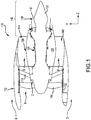
- FIG. 1 illustrates a schematic view of a gas turbine engine, in accordance with various embodiments.
- Gas turbine engine 110 may include core engine 120.
- Core engine 120 may include an inlet, a compressor section, a combustor section, a turbine section, and an exhaust section 140.
- Core air flow C flows through core engine 120 and is expelled through exhaust outlet 118 surrounding tail cone 122.
- Exhaust outlet 118 may comprise an aerodynamic throat 130, in accordance with various embodiments.
- Core engine 120 drives a fan 114 arranged in a bypass flow path B.
- Air in bypass flow-path B flows in the aft direction (z-direction) along bypass flow-path B.
- At least a portion of bypass flow path B may be defined by nacelle 112 and inner fixed structure (IFS) 126.
- Fan case 132 may surround fan 114.
- Fan case 132 may be housed within nacelle 112. In this regard, fan case 132 may at least partially define bypass flow path B. Air may flow in the aft direction relative to and radially outward from nacelle 112 in free stream flow path D.
- Nacelle 112 typically comprises two halves which are typically mounted to a pylon. According to various embodiments, multiple guide vanes 116 may extend radially between core engine 120 and fan case 132. Upper bifurcation 144 and lower bifurcation 142 may extend radially between the nacelle 112 and IFS 126 in locations opposite one another to accommodate engine components such as wires and fluids, for example.
- Inner fixed structure 126 surrounds core engine 120 and provides core compartments 128.
- Various components may be provided in core compartment 128 such as fluid conduits and/or compressed air ducts, for example.
- core compartment 128 may comprise an engine bay.
- the pressure forward of an aerodynamic throat 130 is generally greater than the pressure aft of the aerodynamic throat 130.
- a pressure gradient may exist across a gas turbine engine exhaust flow path.
- the aerodynamic throat 130 may be located aft of a turbine section of core engine 120.
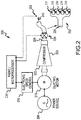
- Cooling air system 200 may include an electric motor 210 and a compressor 220 mechanically coupled to electric motor 210.
- compressor 220 may be mechanically coupled to electric motor 210 via a shaft.
- Electric motor 210 may drive compressor 220.
- compressor 220 may comprise a rotating member which rotates in response to electric motor 210.
- electric motor 210 may comprise a brushless motor.
- electric motor 210 may comprise a brushed motor.
- electric motor 210 may comprise an AC electric motor comprising a three-phase induction motor.
- compressor 220 may comprise an inlet 222 and an outlet 224. Air may enter compressor 220 via inlet 222, be compressed in compressor 220, and the compressed air may exit compressor 220 via outlet 224.
- a controllable valve (valve) 226 may be coupled to outlet 224. While the airflow through outlet 224 may be controllable via electric motor 210, the airflow through outlet 224 may also be controllable via valve 226.
- Outlet 224 may comprise a single duct or may comprise a plurality of ducts as illustrated by splitter 230. In this regard, a plurality of valves (231, 232, 233, 234, and 235) may be individually controlled via microprocessor 214.
- Each valve of splitter 230 may control cooling air 240 being supplied to various portions of a gas turbine engine.
- an overpressure monitor system may be provided to prevent an overpressure event of cooling air system 200.
- a pressure sensor may be provided between compressor 220 and valve 226 and valve 226 may be opened in response to the pressure sensor sensing a pressure above a threshold value.
- electric motor 210 may receive electrical power from power source 208.
- power source 208 may comprise a generator, a fuel cell, a battery, or any other suitable power source capable of being stored onboard an aircraft.
- Electric motor 210 may be in electronic communication with an electronic speed control 212.
- electronic speed control 212 may comprise a variable frequency drive (VFD).
- VFD variable frequency drive
- electronic speed control 212 may control the rotational speed of electric motor 210.
- Electronic speed control 212 may be in electronic communication with microprocessor 214.
- microprocessor 214 may comprise a full authority digital engine control (FADEC). Microprocessor 214 may send signals to electronic speed control 212 for controlling the speed of electric motor 210.
- FADEC full authority digital engine control
- Microprocessor 214 may be in electronic communication with valve 226.
- a moveable member of valve 226 may be controllable via microprocessor 214 for opening and closing valve 226.
- the moveable portion may be actuated between a fully open position and a fully closed position, and any position therebetween.
- a temperature sensor 228 may be located on or in close proximity to outlet 224.
- temperature sensor 228 may be coupled to an exhaust component.
- Temperature sensor 228 may provide feedback to microprocessor 214.
- Microprocessor 214 may control valve 226 in response to a signal received from temperature sensor 228.
- valve 226 may be opened in response to a signal indicating an increase in temperature and valve 226 may be closed in response to a signal indicating a decrease in temperature.
- air entering inlet 222 may comprise free stream air.
- freestream air depending on aircraft location geographically as well as altitude, may comprise temperatures of between about -70°F (-56.7°C) and about 120°F (48.9°C).
- outlet 224 may direct cooling air 240 to an exhaust component located aft of the aerodynamic throat 130 of an exhaust outlet 118. It should be appreciated by those having ordinary skill in the art that pressure aft of the aerodynamic throat 130 is low relative to the pressure forward of the aerodynamic throat 130. Coupling outlet 224 to exhaust section 140 at a location aft of aerodynamic throat 130 may allow for a smaller compressor 220 because the compressor 220 would only have to create enough pressure to overcome the relatively low pressure aft of the aerodynamic throat 130. Thus, in various embodiments, the cooling air system 200 may be relatively compact and lightweight.
- FIGs. 3A through FIG. 5 provide various embodiments of outlet 224 coupled to an exhaust section.
- exhaust section 340 receiving cooling air 240 from the cooling air system 200 of FIG. 2 is illustrated, in accordance with various embodiments.
- exhaust section 340 may be similar to the exhaust section 140 of FIG. 1 .
- Exhaust section 340 may include a nozzle 310.
- nozzle 310 may actuate to vary the cross-section area (in the x-y plane) of exhaust outlet 330.
- the actuating of nozzle 310 may meter the flow of exhaust gas 312 exiting nozzle 310.
- exhaust section 340 may include a cooling duct 320.
- cooling duct 320 may comprise an annular geometry.
- cooling duct 320 may comprise a segmented annular geometry.
- the cross-section (in the y-z plane) of cooling duct 320 may comprise a generally "C" shape, or sideways "U" shaped, geometry, as illustrated in FIG. 3A .
- Cooling duct 320 may be coupled to outlet 224 of FIG. 2 . Stated another way, outlet 224 (see FIG. 2 ) may comprise cooling duct 320.
- cooling duct 320 may comprise an exit 322.
- exit 322 may comprise a slit or slot.
- exit 322 may be partially defined by nozzle 310.
- Cooling duct 320 may receive cooling air 240 and may direct cooling air 240 towards nozzle 310.
- cooling air 240 may be directed towards a radially inwards portion 316 of nozzle 310.
- cooling air 240 may provide film cooling to nozzle 310.
- cooling duct 320 may be coupled to exhaust structure 314.
- cooling duct 320 may be located forward of nozzle 310.
- exhaust section 340 may include a cooling hole 350.
- Cooling hole 350 may be coupled to outlet 224 of FIG. 2 . Stated another way, outlet 224 (see FIG. 2 ) may comprise cooling hole 350.
- Cooling hole 350 may extend through exhaust structure 314. Cooling hole 350 may receive cooling air 240 and may direct cooling air 240 towards nozzle 310. Cooling hole 350 may receive cooling air 240 and may direct cooling air 240 towards inner surface 318 of exhaust structure 314. In various embodiments, cooling hole 350 may be located forward of nozzle 310.
- cooling hole 350 may comprise a circular, ovular, square, rectangular, or slit shaped geometry. For example, cooling hole 350 may comprise a slit shaped exit circumferentially disposed around exhaust structure 314.
- exhaust structure 314 may comprise an engine case, an inner fixed structure, a nacelle or portion thereof, or an exhaust outlet, including a variable area nozzle, a wing or portion thereof, such as a wash deck, etc.
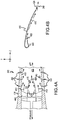
- exhaust section 440 receiving cooling air 240 from the cooling air system 200 of FIG. 2 is illustrated, in accordance with various embodiments.
- exhaust section 440 may be similar to the exhaust section 140 of FIG. 1 .
- Exhaust section 440 may include a tail cone 410.
- Exhaust section 440 may include an exhaust outlet 430.
- exhaust section 440 may include a cooling duct 420.
- cooling duct 420 may comprise an annular geometry.
- cooling duct 420 may comprise a segmented annular geometry.
- the cross-section (in the y-z plane) of cooling duct 420 may comprise a generally "C" shape, or sideways "U" shaped, geometry, as illustrated in FIG. 4A and FIG. 4B .
- Cooling duct 420 may be coupled to outlet 224 of FIG. 2 . Stated another way, outlet 224 (see FIG. 2 ) may comprise cooling duct 420.
- cooling duct 420 may comprise an exit 422.
- exit 422 may comprise a high aspect ratio opening, such as a slit or slot for example.
- exit 422 may be partially defined by tail cone 410.
- exit 422 may comprise an annular slit or slot.
- Cooling duct 420 may receive cooling air 240 and may direct cooling air 240 towards tail cone 410.
- cooling air 240 may be directed towards an inner surface 416 of tail cone 410.
- cooling air 240 may provide convection cooling to tail cone 410.
- exhaust gas 412 may transfer heat to tail cone 410 and the heat may be transferred from tail cone 410 to cooling air 240 by which the heat may be carried out, by the cooling air 240, through the exhaust outlet 430.
- Cooling air 240 may exit tail cone 410 via tail cone exit 424.
- Tail cone exit 424 may comprise an aperture disposed in the tip of tail cone 410.
- Tail cone exit 424 may be concentric with tail cone 410.
- cooling duct 420 may be coupled to tail cone 410.
- cooling duct 420 may be located at a forward end of tail cone 410.
- cooling duct 420 may be integrally manufactured with tail cone 410.
- outlet 224 (see FIG. 2 ) may be coupled to cooling duct 420 through bifurcation 460.
- exhaust section 440 may include cooling holes 450.
- Cooling holes 450 may be coupled to outlet 224 of FIG. 2 . Stated another way, outlet 224 (see FIG. 2 ) may comprise cooling holes 450. Cooling holes 450 may extend through exhaust structure 414. Cooling holes 450 may receive cooling air 240 and may direct cooling air 240 into exhaust outlet 430. Cooling holes 450 may receive cooling air 240 and may direct cooling air 240 towards inner surface 418 of exhaust structure 414. In this regard, cooling air 240 may provide film cooling to inner surface 418 of exhaust structure 414. Cooling holes 450 may be located radially outward of tail cone 410.
- exhaust structure 414 may comprise an engine case, an inner fixed structure, a nacelle or portion thereof, or an exhaust outlet, including a variable area nozzle, a wing or portion thereof, such as a wash deck, etc.
- an exhaust outlet 530 is illustrated receiving cooling air 240 from compressor 220, in accordance with various embodiments.
- an exhaust section 540 may include an exhaust structure 514 defining an exhaust outlet 530.
- exhaust structure 514 may comprise a wing, a wing wash deck, a wing flap, a nacelle, a nozzle, or any other exhaust structure.
- Exhaust gas 512 may flow in the aft direction through exhaust outlet 530.
- Exhaust outlet 530 may be defined by first surface 564 and second surface 566.
- first surface 564 may comprise an outer surface and second surface 566 may comprise an inner surface.
- first surface 564 may comprise an upper surface and second surface 566 may comprise a lower surface.
- Exhaust structure 514 may comprise a surface 562.
- surface 562 may comprise an outer surface of a wing, a wing wash deck, a wing flap, a nacelle, a nozzle, or any other exhaust structure.
- surface 562 may be exposed to air flow E.
- surface 562 may comprise an aerodynamically smooth surface and thus may be referred to herein as an aerodynamic surface.
- air flow E may comprise free stream flow path D (see FIG. 1 ).
- air flow E may comprise bypass flow path B (see FIG. 1 ).
- Compressor 220 and electric motor 210 may be coupled between exhaust outlet 530 and surface 562. Air in air flow E may enter compressor 220 and exit as compressed cooling air 240 in or aft of exhaust outlet 530. In this regard, cooling air 240 may provide film cooling to second surface 566.
- air flow E may comprise engine bay air.
- An engine bay may refer to a void wherein an engine is housed.
- inlet 210 may be coupled to core compartment 128 (see FIG. 1 ).
- surface 562 may comprise the radially inner surface of IFS 126.
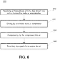
- Method 600 includes receiving air from at least one of a free stream flow path, a bypass flow path, or an engine bay (step 610).
- Method 600 includes driving, by an electric motor, a compressor (step 620).
- Method 600 includes compressing, by the compressor, the air (step 630).
- Method 600 includes receiving, by a gas turbine engine, the air (step 640).
- step 610 may include receiving, by compressor 220, air from at least one of free stream flow path D, bypass flow path B, or an engine bay (i.e., core compartment 128).
- Step 620 may include driving, by electric motor 210, the compressor 220.
- Step 630 may include compressing, by compressor 220, the air.
- Step 640 may include receiving, by at least a portion of the gas turbine engine (i.e., nozzle 310, tail cone 410, exhaust structures 314, 414, and/or 514) the compressed air (i.e., cooling air 240).
- references to "one embodiment”, “an embodiment”, “various embodiments”, etc. indicate that the embodiment described may include a particular feature, structure, or characteristic, but every embodiment may not necessarily include the particular feature, structure, or characteristic. Moreover, such phrases are not necessarily referring to the same embodiment. Further, when a particular feature, structure, or characteristic is described in connection with an embodiment, it is submitted that it is within the knowledge of one skilled in the art to affect such feature, structure, or characteristic in connection with other embodiments whether or not explicitly described. After reading the description, it will be apparent to one skilled in the relevant art(s) how to implement the disclosure in alternative embodiments.
Landscapes
- Engineering & Computer Science (AREA)
- Mechanical Engineering (AREA)
- General Engineering & Computer Science (AREA)
- Chemical & Material Sciences (AREA)
- Combustion & Propulsion (AREA)
- Aviation & Aerospace Engineering (AREA)
- Physics & Mathematics (AREA)
- Fluid Mechanics (AREA)
- Structures Of Non-Positive Displacement Pumps (AREA)
Applications Claiming Priority (1)
| Application Number | Priority Date | Filing Date | Title |
|---|---|---|---|
| US15/256,104 US11105265B2 (en) | 2016-09-02 | 2016-09-02 | Supplemental cooling air for turbine exhaust components and surfaces |
Publications (2)
| Publication Number | Publication Date |
|---|---|
| EP3290659A1 true EP3290659A1 (de) | 2018-03-07 |
| EP3290659B1 EP3290659B1 (de) | 2022-03-09 |
Family
ID=59579501
Family Applications (1)
| Application Number | Title | Priority Date | Filing Date |
|---|---|---|---|
| EP17185566.1A Active EP3290659B1 (de) | 2016-09-02 | 2017-08-09 | Zusätzliche kühlluft für turbinenabgaskomponenten und -oberflächen |
Country Status (2)
| Country | Link |
|---|---|
| US (1) | US11105265B2 (de) |
| EP (1) | EP3290659B1 (de) |
Cited By (5)
| Publication number | Priority date | Publication date | Assignee | Title |
|---|---|---|---|---|
| EP3553295A1 (de) * | 2018-04-12 | 2019-10-16 | United Technologies Corporation | Wärmeverwaltung eines im abgaskonus montierten generators |
| EP3628598A1 (de) * | 2018-09-26 | 2020-04-01 | Rohr, Inc. | Stromrichterkühlung |
| EP3892546A1 (de) * | 2020-04-07 | 2021-10-13 | Rohr, Inc. | Transpirationsgekühlter abgaszentralkörper für ein flugzeugantriebssystem |
| CN114750965A (zh) * | 2022-06-15 | 2022-07-15 | 中国空气动力研究与发展中心设备设计与测试技术研究所 | 一种基于仿生叶脉的冷却装置 |
| US12246844B1 (en) * | 2023-11-29 | 2025-03-11 | Pratt & Whitney Canada Corp. | Hybrid aircraft power plant |
Families Citing this family (3)
| Publication number | Priority date | Publication date | Assignee | Title |
|---|---|---|---|---|
| FR3117093B1 (fr) * | 2020-12-03 | 2024-03-22 | Airbus Sas | Système de propulsion électrique d’un aéronef. |
| US12497185B2 (en) * | 2022-12-28 | 2025-12-16 | Joby Aero, Inc. | Managing cooling airflow using variable-geometry openings |
| GB2634529A (en) * | 2023-10-11 | 2025-04-16 | Rolls Royce Plc | System for cooling components associated with gas turbine engine |
Citations (4)
| Publication number | Priority date | Publication date | Assignee | Title |
|---|---|---|---|---|
| US8858161B1 (en) * | 2007-11-29 | 2014-10-14 | Florida Turbine Technologies, Inc. | Multiple staged compressor with last stage airfoil cooling |
| US20150275769A1 (en) * | 2014-04-01 | 2015-10-01 | The Boeing Company | Bleed air systems for use with aircraft and related methods |
| EP2960467A1 (de) * | 2014-06-27 | 2015-12-30 | Frederick M. Schwarz | Niederdruckzapfluftentnahme für klimatisierungssystem eines flugzeugs |
| US20160069264A1 (en) * | 2013-07-22 | 2016-03-10 | Joseph D. Brostmeyer | Gas turbine engine with turbine cooling and combustor air preheating |
Family Cites Families (19)
| Publication number | Priority date | Publication date | Assignee | Title |
|---|---|---|---|---|
| US2789416A (en) * | 1953-08-26 | 1957-04-23 | Fairchild Engine & Airplane | System for cooling a turbine bearing of a gas turbine power plant |
| US3528246A (en) * | 1966-12-29 | 1970-09-15 | Helen M Fischer | Fan arrangement for high bypass ratio turbofan engine |
| US3543873A (en) * | 1968-03-19 | 1970-12-01 | William W Toy | Turbine and electric powered vehicle |
| US5136837A (en) * | 1990-03-06 | 1992-08-11 | General Electric Company | Aircraft engine starter integrated boundary bleed system |
| US5414992A (en) * | 1993-08-06 | 1995-05-16 | United Technologies Corporation | Aircraft cooling method |
| US5379583A (en) * | 1993-12-08 | 1995-01-10 | United Technologies Corporation | Closed loop stator vane control |
| US5553449A (en) * | 1993-12-21 | 1996-09-10 | United Technologies Corporation | Method of operating a gas turbine engine powerplant for an aircraft |
| US5724806A (en) * | 1995-09-11 | 1998-03-10 | General Electric Company | Extracted, cooled, compressed/intercooled, cooling/combustion air for a gas turbine engine |
| US5813609A (en) * | 1996-12-11 | 1998-09-29 | General Electric Company | Hinged lined exhaust nozzle |
| US6578362B1 (en) * | 1999-05-17 | 2003-06-17 | General Electric Co. | Methods and apparatus for supplying cooling air to turbine engines |
| US7805925B2 (en) * | 2006-08-18 | 2010-10-05 | Pratt & Whitney Canada Corp. | Gas turbine engine exhaust duct ventilation |
| US7779811B1 (en) * | 2006-09-13 | 2010-08-24 | General Electric Company | Thermoelectrically cooled components for distributed electronics control system for gas turbine engines |
| US8095145B2 (en) * | 2007-03-27 | 2012-01-10 | Telcom Ventures, Llc | Method and system of distributing transmissions in a wireless data transmission system |
| US8092153B2 (en) * | 2008-12-16 | 2012-01-10 | Pratt & Whitney Canada Corp. | Bypass air scoop for gas turbine engine |
| GB2468346B (en) * | 2009-03-06 | 2011-06-22 | Rolls Royce Plc | Cooling system for an aero gas turbine engine |
| TWI439976B (zh) * | 2009-04-17 | 2014-06-01 | Ind Tech Res Inst | 可撓曲膜自載板上脫離的方法及可撓式電子裝置的製造方法 |
| US8893510B2 (en) * | 2012-11-07 | 2014-11-25 | Siemens Aktiengesellschaft | Air injection system in a gas turbine engine |
| BR112016007478A2 (pt) * | 2013-10-07 | 2017-08-01 | Ge Aviat Systems Ltd | método para diagnosticar uma falha de unidade auxiliar de potência em uma aeronave |
| US9409653B2 (en) * | 2014-09-17 | 2016-08-09 | The Boeing Company | Auxilliary power and thrust unit drive system |
-
2016
- 2016-09-02 US US15/256,104 patent/US11105265B2/en active Active
-
2017
- 2017-08-09 EP EP17185566.1A patent/EP3290659B1/de active Active
Patent Citations (4)
| Publication number | Priority date | Publication date | Assignee | Title |
|---|---|---|---|---|
| US8858161B1 (en) * | 2007-11-29 | 2014-10-14 | Florida Turbine Technologies, Inc. | Multiple staged compressor with last stage airfoil cooling |
| US20160069264A1 (en) * | 2013-07-22 | 2016-03-10 | Joseph D. Brostmeyer | Gas turbine engine with turbine cooling and combustor air preheating |
| US20150275769A1 (en) * | 2014-04-01 | 2015-10-01 | The Boeing Company | Bleed air systems for use with aircraft and related methods |
| EP2960467A1 (de) * | 2014-06-27 | 2015-12-30 | Frederick M. Schwarz | Niederdruckzapfluftentnahme für klimatisierungssystem eines flugzeugs |
Cited By (9)
| Publication number | Priority date | Publication date | Assignee | Title |
|---|---|---|---|---|
| EP3553295A1 (de) * | 2018-04-12 | 2019-10-16 | United Technologies Corporation | Wärmeverwaltung eines im abgaskonus montierten generators |
| US10801410B2 (en) | 2018-04-12 | 2020-10-13 | Raytheon Technologies Corporation | Thermal management of tail cone mounted generator |
| US11702986B2 (en) | 2018-04-12 | 2023-07-18 | Raytheon Technologies Corporation | Thermal management of tail cone mounted generator |
| EP3628598A1 (de) * | 2018-09-26 | 2020-04-01 | Rohr, Inc. | Stromrichterkühlung |
| US11343947B2 (en) | 2018-09-26 | 2022-05-24 | Rohr, Inc. | Power converter cooling |
| EP3892546A1 (de) * | 2020-04-07 | 2021-10-13 | Rohr, Inc. | Transpirationsgekühlter abgaszentralkörper für ein flugzeugantriebssystem |
| CN114750965A (zh) * | 2022-06-15 | 2022-07-15 | 中国空气动力研究与发展中心设备设计与测试技术研究所 | 一种基于仿生叶脉的冷却装置 |
| CN114750965B (zh) * | 2022-06-15 | 2022-09-13 | 中国空气动力研究与发展中心设备设计与测试技术研究所 | 一种基于仿生叶脉的冷却装置 |
| US12246844B1 (en) * | 2023-11-29 | 2025-03-11 | Pratt & Whitney Canada Corp. | Hybrid aircraft power plant |
Also Published As
| Publication number | Publication date |
|---|---|
| US20180066584A1 (en) | 2018-03-08 |
| US11105265B2 (en) | 2021-08-31 |
| EP3290659B1 (de) | 2022-03-09 |
Similar Documents
| Publication | Publication Date | Title |
|---|---|---|
| US11105265B2 (en) | Supplemental cooling air for turbine exhaust components and surfaces | |
| EP3862542B1 (de) | Kühlsystem für stromkabel in einem gasturbinenmotor | |
| EP3659908B1 (de) | Wärmeverwaltungssystem für einen antriebsmotor | |
| US10583933B2 (en) | Method and apparatus for undercowl flow diversion cooling | |
| EP3421366B1 (de) | Hybridelektrisches antriebssystem für ein flugzeug | |
| US10634050B2 (en) | Air circulation device for a turbomachine comprising a hot air bypass system to a heat exchanger | |
| CN116412042B (zh) | 三流燃气涡轮发动机控制 | |
| US20220128004A1 (en) | Power cable cooling system in a gas turbine engine | |
| EP4194679B1 (de) | Heckkonusejektor für stromkabelkühlsystem in einem gasturbinenmotor | |
| US20250354518A1 (en) | Gas turbine engine having cooling systems | |
| US10585007B2 (en) | Air temperature sensor | |
| US20230095723A1 (en) | Turbine engine with variable pitch fan | |
| EP3869022B1 (de) | Nachlüftersystem mit elektromotor für gasturbinenmotoren | |
| US12416262B2 (en) | Reverse flow gas turbine engine having electric machine | |
| EP4733566A2 (de) | Wärmeverwaltungssystem für ein flugzeugantriebssystem mit offenem rotor | |
| US12460574B2 (en) | Gas turbine engine having cooling systems | |
| US20250334055A1 (en) | Gas turbine engine having cooling systems | |
| US20250347252A1 (en) | Gas turbine engine having cooling systems | |
| US20250347251A1 (en) | Gas turbine engine having cooling systems | |
| US20250389225A1 (en) | Gas turbine engine having cooling systems | |
| US20250347258A1 (en) | Gas turbine engine having cooling systems | |
| US20250389226A1 (en) | Gas turbine engine having cooling systems | |
| US20250354519A1 (en) | Gas turbine engine having cooling systems | |
| EP4431385A1 (de) | Wärmetauscheranordnung für ein flugzeug | |
| US20250197013A1 (en) | Open rotor aircraft propulsion system with anti-icing system |
Legal Events
| Date | Code | Title | Description |
|---|---|---|---|
| PUAI | Public reference made under article 153(3) epc to a published international application that has entered the european phase |
Free format text: ORIGINAL CODE: 0009012 |
|
| STAA | Information on the status of an ep patent application or granted ep patent |
Free format text: STATUS: THE APPLICATION HAS BEEN PUBLISHED |
|
| AK | Designated contracting states |
Kind code of ref document: A1 Designated state(s): AL AT BE BG CH CY CZ DE DK EE ES FI FR GB GR HR HU IE IS IT LI LT LU LV MC MK MT NL NO PL PT RO RS SE SI SK SM TR |
|
| AX | Request for extension of the european patent |
Extension state: BA ME |
|
| STAA | Information on the status of an ep patent application or granted ep patent |
Free format text: STATUS: REQUEST FOR EXAMINATION WAS MADE |
|
| 17P | Request for examination filed |
Effective date: 20180906 |
|
| RBV | Designated contracting states (corrected) |
Designated state(s): AL AT BE BG CH CY CZ DE DK EE ES FI FR GB GR HR HU IE IS IT LI LT LU LV MC MK MT NL NO PL PT RO RS SE SI SK SM TR |
|
| STAA | Information on the status of an ep patent application or granted ep patent |
Free format text: STATUS: EXAMINATION IS IN PROGRESS |
|
| 17Q | First examination report despatched |
Effective date: 20200312 |
|
| RAP1 | Party data changed (applicant data changed or rights of an application transferred) |
Owner name: RAYTHEON TECHNOLOGIES CORPORATION |
|
| GRAP | Despatch of communication of intention to grant a patent |
Free format text: ORIGINAL CODE: EPIDOSNIGR1 |
|
| STAA | Information on the status of an ep patent application or granted ep patent |
Free format text: STATUS: GRANT OF PATENT IS INTENDED |
|
| INTG | Intention to grant announced |
Effective date: 20210928 |
|
| GRAS | Grant fee paid |
Free format text: ORIGINAL CODE: EPIDOSNIGR3 |
|
| GRAA | (expected) grant |
Free format text: ORIGINAL CODE: 0009210 |
|
| STAA | Information on the status of an ep patent application or granted ep patent |
Free format text: STATUS: THE PATENT HAS BEEN GRANTED |
|
| AK | Designated contracting states |
Kind code of ref document: B1 Designated state(s): AL AT BE BG CH CY CZ DE DK EE ES FI FR GB GR HR HU IE IS IT LI LT LU LV MC MK MT NL NO PL PT RO RS SE SI SK SM TR |
|
| REG | Reference to a national code |
Ref country code: CH Ref legal event code: EP Ref country code: AT Ref legal event code: REF Ref document number: 1474316 Country of ref document: AT Kind code of ref document: T Effective date: 20220315 |
|
| REG | Reference to a national code |
Ref country code: DE Ref legal event code: R096 Ref document number: 602017054281 Country of ref document: DE |
|
| REG | Reference to a national code |
Ref country code: IE Ref legal event code: FG4D |
|
| REG | Reference to a national code |
Ref country code: LT Ref legal event code: MG9D |
|
| REG | Reference to a national code |
Ref country code: NL Ref legal event code: MP Effective date: 20220309 |
|
| PG25 | Lapsed in a contracting state [announced via postgrant information from national office to epo] |
Ref country code: SE Free format text: LAPSE BECAUSE OF FAILURE TO SUBMIT A TRANSLATION OF THE DESCRIPTION OR TO PAY THE FEE WITHIN THE PRESCRIBED TIME-LIMIT Effective date: 20220309 Ref country code: RS Free format text: LAPSE BECAUSE OF FAILURE TO SUBMIT A TRANSLATION OF THE DESCRIPTION OR TO PAY THE FEE WITHIN THE PRESCRIBED TIME-LIMIT Effective date: 20220309 Ref country code: NO Free format text: LAPSE BECAUSE OF FAILURE TO SUBMIT A TRANSLATION OF THE DESCRIPTION OR TO PAY THE FEE WITHIN THE PRESCRIBED TIME-LIMIT Effective date: 20220609 Ref country code: LT Free format text: LAPSE BECAUSE OF FAILURE TO SUBMIT A TRANSLATION OF THE DESCRIPTION OR TO PAY THE FEE WITHIN THE PRESCRIBED TIME-LIMIT Effective date: 20220309 Ref country code: HR Free format text: LAPSE BECAUSE OF FAILURE TO SUBMIT A TRANSLATION OF THE DESCRIPTION OR TO PAY THE FEE WITHIN THE PRESCRIBED TIME-LIMIT Effective date: 20220309 Ref country code: BG Free format text: LAPSE BECAUSE OF FAILURE TO SUBMIT A TRANSLATION OF THE DESCRIPTION OR TO PAY THE FEE WITHIN THE PRESCRIBED TIME-LIMIT Effective date: 20220609 |
|
| REG | Reference to a national code |
Ref country code: AT Ref legal event code: MK05 Ref document number: 1474316 Country of ref document: AT Kind code of ref document: T Effective date: 20220309 |
|
| PG25 | Lapsed in a contracting state [announced via postgrant information from national office to epo] |
Ref country code: LV Free format text: LAPSE BECAUSE OF FAILURE TO SUBMIT A TRANSLATION OF THE DESCRIPTION OR TO PAY THE FEE WITHIN THE PRESCRIBED TIME-LIMIT Effective date: 20220309 Ref country code: GR Free format text: LAPSE BECAUSE OF FAILURE TO SUBMIT A TRANSLATION OF THE DESCRIPTION OR TO PAY THE FEE WITHIN THE PRESCRIBED TIME-LIMIT Effective date: 20220610 Ref country code: FI Free format text: LAPSE BECAUSE OF FAILURE TO SUBMIT A TRANSLATION OF THE DESCRIPTION OR TO PAY THE FEE WITHIN THE PRESCRIBED TIME-LIMIT Effective date: 20220309 |
|
| PG25 | Lapsed in a contracting state [announced via postgrant information from national office to epo] |
Ref country code: NL Free format text: LAPSE BECAUSE OF FAILURE TO SUBMIT A TRANSLATION OF THE DESCRIPTION OR TO PAY THE FEE WITHIN THE PRESCRIBED TIME-LIMIT Effective date: 20220309 |
|
| PG25 | Lapsed in a contracting state [announced via postgrant information from national office to epo] |
Ref country code: SM Free format text: LAPSE BECAUSE OF FAILURE TO SUBMIT A TRANSLATION OF THE DESCRIPTION OR TO PAY THE FEE WITHIN THE PRESCRIBED TIME-LIMIT Effective date: 20220309 Ref country code: SK Free format text: LAPSE BECAUSE OF FAILURE TO SUBMIT A TRANSLATION OF THE DESCRIPTION OR TO PAY THE FEE WITHIN THE PRESCRIBED TIME-LIMIT Effective date: 20220309 Ref country code: RO Free format text: LAPSE BECAUSE OF FAILURE TO SUBMIT A TRANSLATION OF THE DESCRIPTION OR TO PAY THE FEE WITHIN THE PRESCRIBED TIME-LIMIT Effective date: 20220309 Ref country code: PT Free format text: LAPSE BECAUSE OF FAILURE TO SUBMIT A TRANSLATION OF THE DESCRIPTION OR TO PAY THE FEE WITHIN THE PRESCRIBED TIME-LIMIT Effective date: 20220711 Ref country code: ES Free format text: LAPSE BECAUSE OF FAILURE TO SUBMIT A TRANSLATION OF THE DESCRIPTION OR TO PAY THE FEE WITHIN THE PRESCRIBED TIME-LIMIT Effective date: 20220309 Ref country code: EE Free format text: LAPSE BECAUSE OF FAILURE TO SUBMIT A TRANSLATION OF THE DESCRIPTION OR TO PAY THE FEE WITHIN THE PRESCRIBED TIME-LIMIT Effective date: 20220309 Ref country code: CZ Free format text: LAPSE BECAUSE OF FAILURE TO SUBMIT A TRANSLATION OF THE DESCRIPTION OR TO PAY THE FEE WITHIN THE PRESCRIBED TIME-LIMIT Effective date: 20220309 Ref country code: AT Free format text: LAPSE BECAUSE OF FAILURE TO SUBMIT A TRANSLATION OF THE DESCRIPTION OR TO PAY THE FEE WITHIN THE PRESCRIBED TIME-LIMIT Effective date: 20220309 |
|
| PG25 | Lapsed in a contracting state [announced via postgrant information from national office to epo] |
Ref country code: PL Free format text: LAPSE BECAUSE OF FAILURE TO SUBMIT A TRANSLATION OF THE DESCRIPTION OR TO PAY THE FEE WITHIN THE PRESCRIBED TIME-LIMIT Effective date: 20220309 Ref country code: IS Free format text: LAPSE BECAUSE OF FAILURE TO SUBMIT A TRANSLATION OF THE DESCRIPTION OR TO PAY THE FEE WITHIN THE PRESCRIBED TIME-LIMIT Effective date: 20220709 Ref country code: AL Free format text: LAPSE BECAUSE OF FAILURE TO SUBMIT A TRANSLATION OF THE DESCRIPTION OR TO PAY THE FEE WITHIN THE PRESCRIBED TIME-LIMIT Effective date: 20220309 |
|
| REG | Reference to a national code |
Ref country code: DE Ref legal event code: R097 Ref document number: 602017054281 Country of ref document: DE |
|
| PLBE | No opposition filed within time limit |
Free format text: ORIGINAL CODE: 0009261 |
|
| STAA | Information on the status of an ep patent application or granted ep patent |
Free format text: STATUS: NO OPPOSITION FILED WITHIN TIME LIMIT |
|
| PG25 | Lapsed in a contracting state [announced via postgrant information from national office to epo] |
Ref country code: DK Free format text: LAPSE BECAUSE OF FAILURE TO SUBMIT A TRANSLATION OF THE DESCRIPTION OR TO PAY THE FEE WITHIN THE PRESCRIBED TIME-LIMIT Effective date: 20220309 |
|
| 26N | No opposition filed |
Effective date: 20221212 |
|
| PG25 | Lapsed in a contracting state [announced via postgrant information from national office to epo] |
Ref country code: SI Free format text: LAPSE BECAUSE OF FAILURE TO SUBMIT A TRANSLATION OF THE DESCRIPTION OR TO PAY THE FEE WITHIN THE PRESCRIBED TIME-LIMIT Effective date: 20220309 |
|
| PG25 | Lapsed in a contracting state [announced via postgrant information from national office to epo] |
Ref country code: MC Free format text: LAPSE BECAUSE OF FAILURE TO SUBMIT A TRANSLATION OF THE DESCRIPTION OR TO PAY THE FEE WITHIN THE PRESCRIBED TIME-LIMIT Effective date: 20220309 |
|
| REG | Reference to a national code |
Ref country code: CH Ref legal event code: PL |
|
| PG25 | Lapsed in a contracting state [announced via postgrant information from national office to epo] |
Ref country code: LU Free format text: LAPSE BECAUSE OF NON-PAYMENT OF DUE FEES Effective date: 20220809 Ref country code: LI Free format text: LAPSE BECAUSE OF NON-PAYMENT OF DUE FEES Effective date: 20220831 Ref country code: CH Free format text: LAPSE BECAUSE OF NON-PAYMENT OF DUE FEES Effective date: 20220831 |
|
| REG | Reference to a national code |
Ref country code: BE Ref legal event code: MM Effective date: 20220831 |
|
| P01 | Opt-out of the competence of the unified patent court (upc) registered |
Effective date: 20230520 |
|
| PG25 | Lapsed in a contracting state [announced via postgrant information from national office to epo] |
Ref country code: IT Free format text: LAPSE BECAUSE OF FAILURE TO SUBMIT A TRANSLATION OF THE DESCRIPTION OR TO PAY THE FEE WITHIN THE PRESCRIBED TIME-LIMIT Effective date: 20220309 Ref country code: IE Free format text: LAPSE BECAUSE OF NON-PAYMENT OF DUE FEES Effective date: 20220809 |
|
| PG25 | Lapsed in a contracting state [announced via postgrant information from national office to epo] |
Ref country code: BE Free format text: LAPSE BECAUSE OF NON-PAYMENT OF DUE FEES Effective date: 20220831 |
|
| PG25 | Lapsed in a contracting state [announced via postgrant information from national office to epo] |
Ref country code: HU Free format text: LAPSE BECAUSE OF FAILURE TO SUBMIT A TRANSLATION OF THE DESCRIPTION OR TO PAY THE FEE WITHIN THE PRESCRIBED TIME-LIMIT; INVALID AB INITIO Effective date: 20170809 |
|
| PG25 | Lapsed in a contracting state [announced via postgrant information from national office to epo] |
Ref country code: CY Free format text: LAPSE BECAUSE OF FAILURE TO SUBMIT A TRANSLATION OF THE DESCRIPTION OR TO PAY THE FEE WITHIN THE PRESCRIBED TIME-LIMIT Effective date: 20220309 |
|
| PG25 | Lapsed in a contracting state [announced via postgrant information from national office to epo] |
Ref country code: MK Free format text: LAPSE BECAUSE OF FAILURE TO SUBMIT A TRANSLATION OF THE DESCRIPTION OR TO PAY THE FEE WITHIN THE PRESCRIBED TIME-LIMIT Effective date: 20220309 |
|
| PG25 | Lapsed in a contracting state [announced via postgrant information from national office to epo] |
Ref country code: TR Free format text: LAPSE BECAUSE OF FAILURE TO SUBMIT A TRANSLATION OF THE DESCRIPTION OR TO PAY THE FEE WITHIN THE PRESCRIBED TIME-LIMIT Effective date: 20220309 |
|
| PG25 | Lapsed in a contracting state [announced via postgrant information from national office to epo] |
Ref country code: MT Free format text: LAPSE BECAUSE OF FAILURE TO SUBMIT A TRANSLATION OF THE DESCRIPTION OR TO PAY THE FEE WITHIN THE PRESCRIBED TIME-LIMIT Effective date: 20220309 |
|
| REG | Reference to a national code |
Ref country code: DE Ref legal event code: R081 Ref document number: 602017054281 Country of ref document: DE Owner name: RTX CORPORATION (N.D.GES.D. STAATES DELAWARE),, US Free format text: FORMER OWNER: RAYTHEON TECHNOLOGIES CORPORATION, FARMINGTON, CT, US |
|
| PGFP | Annual fee paid to national office [announced via postgrant information from national office to epo] |
Ref country code: DE Payment date: 20250724 Year of fee payment: 9 |
|
| PGFP | Annual fee paid to national office [announced via postgrant information from national office to epo] |
Ref country code: GB Payment date: 20250725 Year of fee payment: 9 |
|
| PGFP | Annual fee paid to national office [announced via postgrant information from national office to epo] |
Ref country code: FR Payment date: 20250723 Year of fee payment: 9 |