EP3290732B1 - Drive system and drive sub-assembly for driving a shaft - Google Patents
Drive system and drive sub-assembly for driving a shaft Download PDFInfo
- Publication number
- EP3290732B1 EP3290732B1 EP17188301.0A EP17188301A EP3290732B1 EP 3290732 B1 EP3290732 B1 EP 3290732B1 EP 17188301 A EP17188301 A EP 17188301A EP 3290732 B1 EP3290732 B1 EP 3290732B1
- Authority
- EP
- European Patent Office
- Prior art keywords
- hub
- bore
- assembly
- gear
- shaft
- Prior art date
- Legal status (The legal status is an assumption and is not a legal conclusion. Google has not performed a legal analysis and makes no representation as to the accuracy of the status listed.)
- Active
Links
Images




Classifications
-
- F—MECHANICAL ENGINEERING; LIGHTING; HEATING; WEAPONS; BLASTING
- F16—ENGINEERING ELEMENTS AND UNITS; GENERAL MEASURES FOR PRODUCING AND MAINTAINING EFFECTIVE FUNCTIONING OF MACHINES OR INSTALLATIONS; THERMAL INSULATION IN GENERAL
- F16H—GEARING
- F16H1/00—Toothed gearings for conveying rotary motion
- F16H1/02—Toothed gearings for conveying rotary motion without gears having orbital motion
- F16H1/20—Toothed gearings for conveying rotary motion without gears having orbital motion involving more than two intermeshing members
- F16H1/22—Toothed gearings for conveying rotary motion without gears having orbital motion involving more than two intermeshing members with a plurality of driving or driven shafts; with arrangements for dividing torque between two or more intermediate shafts
-
- F—MECHANICAL ENGINEERING; LIGHTING; HEATING; WEAPONS; BLASTING
- F16—ENGINEERING ELEMENTS AND UNITS; GENERAL MEASURES FOR PRODUCING AND MAINTAINING EFFECTIVE FUNCTIONING OF MACHINES OR INSTALLATIONS; THERMAL INSULATION IN GENERAL
- F16H—GEARING
- F16H57/00—General details of gearing
- F16H57/0018—Shaft assemblies for gearings
- F16H57/0025—Shaft assemblies for gearings with gearing elements rigidly connected to a shaft, e.g. securing gears or pulleys by specially adapted splines, keys or methods
-
- B—PERFORMING OPERATIONS; TRANSPORTING
- B01—PHYSICAL OR CHEMICAL PROCESSES OR APPARATUS IN GENERAL
- B01F—MIXING, e.g. DISSOLVING, EMULSIFYING OR DISPERSING
- B01F27/00—Mixers with rotary stirring devices in fixed receptacles; Kneaders
- B01F27/21—Mixers with rotary stirring devices in fixed receptacles; Kneaders characterised by their rotating shafts
- B01F27/213—Mixers with rotary stirring devices in fixed receptacles; Kneaders characterised by their rotating shafts characterised by the connection with the drive
-
- B—PERFORMING OPERATIONS; TRANSPORTING
- B01—PHYSICAL OR CHEMICAL PROCESSES OR APPARATUS IN GENERAL
- B01F—MIXING, e.g. DISSOLVING, EMULSIFYING OR DISPERSING
- B01F35/00—Accessories for mixers; Auxiliary operations or auxiliary devices; Parts or details of general application
- B01F35/30—Driving arrangements; Transmissions; Couplings; Brakes
- B01F35/32—Driving arrangements
-
- B—PERFORMING OPERATIONS; TRANSPORTING
- B01—PHYSICAL OR CHEMICAL PROCESSES OR APPARATUS IN GENERAL
- B01F—MIXING, e.g. DISSOLVING, EMULSIFYING OR DISPERSING
- B01F35/00—Accessories for mixers; Auxiliary operations or auxiliary devices; Parts or details of general application
- B01F35/30—Driving arrangements; Transmissions; Couplings; Brakes
- B01F35/32—Driving arrangements
- B01F35/32005—Type of drive
-
- F—MECHANICAL ENGINEERING; LIGHTING; HEATING; WEAPONS; BLASTING
- F16—ENGINEERING ELEMENTS AND UNITS; GENERAL MEASURES FOR PRODUCING AND MAINTAINING EFFECTIVE FUNCTIONING OF MACHINES OR INSTALLATIONS; THERMAL INSULATION IN GENERAL
- F16C—SHAFTS; FLEXIBLE SHAFTS; ELEMENTS OR CRANKSHAFT MECHANISMS; ROTARY BODIES OTHER THAN GEARING ELEMENTS; BEARINGS
- F16C23/00—Bearings for exclusively rotary movement adjustable for aligning or positioning
- F16C23/06—Ball or roller bearings
-
- F—MECHANICAL ENGINEERING; LIGHTING; HEATING; WEAPONS; BLASTING
- F16—ENGINEERING ELEMENTS AND UNITS; GENERAL MEASURES FOR PRODUCING AND MAINTAINING EFFECTIVE FUNCTIONING OF MACHINES OR INSTALLATIONS; THERMAL INSULATION IN GENERAL
- F16C—SHAFTS; FLEXIBLE SHAFTS; ELEMENTS OR CRANKSHAFT MECHANISMS; ROTARY BODIES OTHER THAN GEARING ELEMENTS; BEARINGS
- F16C25/00—Bearings for exclusively rotary movement adjustable for wear or play
- F16C25/06—Ball or roller bearings
-
- F—MECHANICAL ENGINEERING; LIGHTING; HEATING; WEAPONS; BLASTING
- F16—ENGINEERING ELEMENTS AND UNITS; GENERAL MEASURES FOR PRODUCING AND MAINTAINING EFFECTIVE FUNCTIONING OF MACHINES OR INSTALLATIONS; THERMAL INSULATION IN GENERAL
- F16C—SHAFTS; FLEXIBLE SHAFTS; ELEMENTS OR CRANKSHAFT MECHANISMS; ROTARY BODIES OTHER THAN GEARING ELEMENTS; BEARINGS
- F16C35/00—Rigid support of bearing units; Housings, e.g. caps, covers
- F16C35/04—Rigid support of bearing units; Housings, e.g. caps, covers in the case of ball or roller bearings
- F16C35/06—Mounting or dismounting of ball or roller bearings; Fixing them onto shaft or in housing
- F16C35/07—Fixing them on the shaft or housing with interposition of an element
- F16C35/073—Fixing them on the shaft or housing with interposition of an element between shaft and inner race ring
-
- F—MECHANICAL ENGINEERING; LIGHTING; HEATING; WEAPONS; BLASTING
- F16—ENGINEERING ELEMENTS AND UNITS; GENERAL MEASURES FOR PRODUCING AND MAINTAINING EFFECTIVE FUNCTIONING OF MACHINES OR INSTALLATIONS; THERMAL INSULATION IN GENERAL
- F16H—GEARING
- F16H1/00—Toothed gearings for conveying rotary motion
- F16H1/02—Toothed gearings for conveying rotary motion without gears having orbital motion
-
- F—MECHANICAL ENGINEERING; LIGHTING; HEATING; WEAPONS; BLASTING
- F16—ENGINEERING ELEMENTS AND UNITS; GENERAL MEASURES FOR PRODUCING AND MAINTAINING EFFECTIVE FUNCTIONING OF MACHINES OR INSTALLATIONS; THERMAL INSULATION IN GENERAL
- F16H—GEARING
- F16H55/00—Elements with teeth or friction surfaces for conveying motion; Worms, pulleys or sheaves for gearing mechanisms
- F16H55/02—Toothed members; Worms
- F16H55/17—Toothed wheels
-
- F—MECHANICAL ENGINEERING; LIGHTING; HEATING; WEAPONS; BLASTING
- F16—ENGINEERING ELEMENTS AND UNITS; GENERAL MEASURES FOR PRODUCING AND MAINTAINING EFFECTIVE FUNCTIONING OF MACHINES OR INSTALLATIONS; THERMAL INSULATION IN GENERAL
- F16H—GEARING
- F16H57/00—General details of gearing
- F16H57/02—Gearboxes; Mounting gearing therein
-
- F—MECHANICAL ENGINEERING; LIGHTING; HEATING; WEAPONS; BLASTING
- F16—ENGINEERING ELEMENTS AND UNITS; GENERAL MEASURES FOR PRODUCING AND MAINTAINING EFFECTIVE FUNCTIONING OF MACHINES OR INSTALLATIONS; THERMAL INSULATION IN GENERAL
- F16H—GEARING
- F16H57/00—General details of gearing
- F16H57/02—Gearboxes; Mounting gearing therein
- F16H57/021—Shaft support structures, e.g. partition walls, bearing eyes, casing walls or covers with bearings
-
- F—MECHANICAL ENGINEERING; LIGHTING; HEATING; WEAPONS; BLASTING
- F16—ENGINEERING ELEMENTS AND UNITS; GENERAL MEASURES FOR PRODUCING AND MAINTAINING EFFECTIVE FUNCTIONING OF MACHINES OR INSTALLATIONS; THERMAL INSULATION IN GENERAL
- F16H—GEARING
- F16H57/00—General details of gearing
- F16H57/02—Gearboxes; Mounting gearing therein
- F16H57/023—Mounting or installation of gears or shafts in the gearboxes, e.g. methods or means for assembly
-
- F—MECHANICAL ENGINEERING; LIGHTING; HEATING; WEAPONS; BLASTING
- F16—ENGINEERING ELEMENTS AND UNITS; GENERAL MEASURES FOR PRODUCING AND MAINTAINING EFFECTIVE FUNCTIONING OF MACHINES OR INSTALLATIONS; THERMAL INSULATION IN GENERAL
- F16H—GEARING
- F16H57/00—General details of gearing
- F16H57/02—Gearboxes; Mounting gearing therein
- F16H57/029—Gearboxes; Mounting gearing therein characterised by means for sealing the gearboxes, e.g. to improve airtightness
-
- F—MECHANICAL ENGINEERING; LIGHTING; HEATING; WEAPONS; BLASTING
- F16—ENGINEERING ELEMENTS AND UNITS; GENERAL MEASURES FOR PRODUCING AND MAINTAINING EFFECTIVE FUNCTIONING OF MACHINES OR INSTALLATIONS; THERMAL INSULATION IN GENERAL
- F16H—GEARING
- F16H57/00—General details of gearing
- F16H57/04—Features relating to lubrication or cooling or heating
- F16H57/045—Lubricant storage reservoirs, e.g. reservoirs in addition to a gear sump for collecting lubricant in the upper part of a gear case
- F16H57/0454—Sealings between different partitions of a gearing or to a reservoir
-
- F—MECHANICAL ENGINEERING; LIGHTING; HEATING; WEAPONS; BLASTING
- F16—ENGINEERING ELEMENTS AND UNITS; GENERAL MEASURES FOR PRODUCING AND MAINTAINING EFFECTIVE FUNCTIONING OF MACHINES OR INSTALLATIONS; THERMAL INSULATION IN GENERAL
- F16H—GEARING
- F16H57/00—General details of gearing
- F16H57/04—Features relating to lubrication or cooling or heating
- F16H57/0467—Elements of gearings to be lubricated, cooled or heated
- F16H57/0469—Bearings or seals
- F16H57/0471—Bearing
-
- F—MECHANICAL ENGINEERING; LIGHTING; HEATING; WEAPONS; BLASTING
- F16—ENGINEERING ELEMENTS AND UNITS; GENERAL MEASURES FOR PRODUCING AND MAINTAINING EFFECTIVE FUNCTIONING OF MACHINES OR INSTALLATIONS; THERMAL INSULATION IN GENERAL
- F16C—SHAFTS; FLEXIBLE SHAFTS; ELEMENTS OR CRANKSHAFT MECHANISMS; ROTARY BODIES OTHER THAN GEARING ELEMENTS; BEARINGS
- F16C19/00—Bearings with rolling contact, for exclusively rotary movement
- F16C19/22—Bearings with rolling contact, for exclusively rotary movement with bearing rollers essentially of the same size in one or more circular rows, e.g. needle bearings
- F16C19/34—Bearings with rolling contact, for exclusively rotary movement with bearing rollers essentially of the same size in one or more circular rows, e.g. needle bearings for both radial and axial load
- F16C19/38—Bearings with rolling contact, for exclusively rotary movement with bearing rollers essentially of the same size in one or more circular rows, e.g. needle bearings for both radial and axial load with two or more rows of rollers
- F16C19/383—Bearings with rolling contact, for exclusively rotary movement with bearing rollers essentially of the same size in one or more circular rows, e.g. needle bearings for both radial and axial load with two or more rows of rollers with tapered rollers, i.e. rollers having essentially the shape of a truncated cone
- F16C19/385—Bearings with rolling contact, for exclusively rotary movement with bearing rollers essentially of the same size in one or more circular rows, e.g. needle bearings for both radial and axial load with two or more rows of rollers with tapered rollers, i.e. rollers having essentially the shape of a truncated cone with two rows, i.e. double-row tapered roller bearings
-
- F—MECHANICAL ENGINEERING; LIGHTING; HEATING; WEAPONS; BLASTING
- F16—ENGINEERING ELEMENTS AND UNITS; GENERAL MEASURES FOR PRODUCING AND MAINTAINING EFFECTIVE FUNCTIONING OF MACHINES OR INSTALLATIONS; THERMAL INSULATION IN GENERAL
- F16C—SHAFTS; FLEXIBLE SHAFTS; ELEMENTS OR CRANKSHAFT MECHANISMS; ROTARY BODIES OTHER THAN GEARING ELEMENTS; BEARINGS
- F16C2361/00—Apparatus or articles in engineering in general
- F16C2361/61—Toothed gear systems, e.g. support of pinion shafts
-
- F—MECHANICAL ENGINEERING; LIGHTING; HEATING; WEAPONS; BLASTING
- F16—ENGINEERING ELEMENTS AND UNITS; GENERAL MEASURES FOR PRODUCING AND MAINTAINING EFFECTIVE FUNCTIONING OF MACHINES OR INSTALLATIONS; THERMAL INSULATION IN GENERAL
- F16C—SHAFTS; FLEXIBLE SHAFTS; ELEMENTS OR CRANKSHAFT MECHANISMS; ROTARY BODIES OTHER THAN GEARING ELEMENTS; BEARINGS
- F16C33/00—Parts of bearings; Special methods for making bearings or parts thereof
- F16C33/30—Parts of ball or roller bearings
- F16C33/58—Raceways; Race rings
- F16C33/581—Raceways; Race rings integral with other parts, e.g. with housings or machine elements such as shafts or gear wheels
Definitions
- the present invention relates generally to apparatuses and methods that provide bearing support to a driven shaft that may include an impeller or other device for agitating fluid and may be employed in a mixer or mixing system.
- a rotatable shaft assembly is supported by spherical and/or tapered bearing assemblies. This support is commonly accomplished by placing the bearing assemblies at various axial locations along the rotatable shaft.
- a mixing system may include an output impeller drive shaft that extends into a mixing vessel to drive an impeller and a hollow shaft that may encircle a portion of the output shaft.
- the hollow shaft may be rotationally coupled to the output shaft, and have a gear that is driven to transmit rotational motion to the hollow shaft.
- a first bearing or bearing set may be employed to support the output shaft, while a second bearing or bearing set may be utilized to support the hollow shaft.
- the output shaft may be subject to high load and bending forces due to various mixing conditions during operation of a mixing system. These conditions may include, for example, shaft speed, physical properties of materials to be mixed, and shaft length. These forces may translate into bending forces that may cause the output shaft to deflect radially.
- the first and second bearings or bearing sets may isolate the hollow shaft from the output shaft and the associated bending loads the output shaft experiences. This may prevent the likelihood of the hollow shaft from transmitting undesirable loads to other components of the mixing system.
- the second bearing or bearing set may be separated radially and/or axially from the gear by a portion of, or a separate component attached to a portion of, the hollow shaft which is surrounded by the second bearing or bearing set.
- the rotation of the gear which is transferred to the hollow shaft and thereby the output shaft is not directly supported by either of the first or second bearings or bearing sets.
- each of the first and second bearings or bearing sets may require a respective type of lubricant, for example oil for one bearing and grease for another bearing, to operate. This may require multiple lubricant sources and delivery mechanisms.
- the mixing system may also include a frame assembly and bearing housings (e.g. bearing caps) mounted on the frame assembly which house each of the first and second bearings or bearing sets.
- the bearing housings include multiple components and may be mounted in such a way that bearing bores of respective bearings are not accurately aligned with one another. This can result in misalignment between the output shaft and the hollow shaft.
- US4025136A discloses a means for adjusting a plurality of bearings rotatably supporting a plurality of rotating elements by controlling the axial dimension on the rotating elements and bearing supports to allow one adjustment to align all bearings.
- US5211488A discloses a shaft-mounted bushing for connecting a rotating member to a shaft.
- the bushing includes a frame receiving a hub rotatably mounted therein.
- the hub includes an opening at one end thereof for receiving a shaft from the one end thereof.
- the hub includes a tapered portion which converges inwardly from the one end of the hub and toward the other end thereof.
- a sleeve is mounted into the hub from the one end of the hub and between the tapered portion of the hub and the cylindrical shaft. The outer portion of the sleeve converges inwardly from the one end of the hub and engages the hub.
- the sleeve presents an inward portion which is coaxial with and parallel to the cylindrical shaft for engaging the shaft in force transmitting relation ship therewith.
- the bushing assembly is completed by drawing the sleeve into the hub by way of a fastener located at the other end of the hub.
- a drive sub-assembly may include a hub extending from a first end face to a second end face along a longitudinal axis.
- the hub may have an outer circumferential surface and inner circumferential surface.
- the drive sub-assembly may further include at least a first inner race and first rollers of a first bearing assembly, and a gear attached to the second end face of the hub.
- the gear may have a second inner circumferential surface that may be arranged to engage a second bearing assembly.
- the outer circumferential surface may define a first recess proximate to the first end face, and a shoulder between the first recess and the second end face along the longitudinal axis.
- the first inner race and the first rollers may be mounted on the shoulder, and the first inner circumferential surface may define a second recess proximate to the second end face.
- a drive system for a mixing apparatus may transmit a rotational movement of an input shaft to an output shaft of the mixing apparatus and include a housing having a first housing configured to receive the input shaft and a second housing, the second housing including a cylindrical wall extending from the second housing towards the first housing and arranged to receive the output shaft.
- the drive system may further include a hub mounted on the cylindrical wall, a gear attached to the hub and configured to transmit the rotational movement of the input shaft to the hub, a first bearing assembly operatively positioned between the hub and the first housing, and a second bearing assembly operatively positioned on the cylindrical wall and the gear.
- the drive sub-assembly may include a plurality of seals positioned between the housing and the hub such that a same fluid lubricates the first bearing assembly and the second bearing assembly and is prevented from contacting the output shaft.
- a method for driving an output shaft may include applying a force to a gear causing a rotational movement of a hub, and engaging the output shaft with the hub causing a rotational movement of the output shaft corresponding to the rotational movement of the hub.
- the hub may include an outer circumferential surface that defines a first recess and a shoulder, an inner circumferential surface that defines a second recess, and at least a first inner race and first rollers of a first bearing assembly mounted on the shoulder.
- the gear may be attached to the hub and engage second rollers of a second bearing assembly positioned below the second recess along a longitudinal axis.
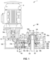
- FIG. 1 illustrates a motor 10 and a cross-sectional view of a drive system 100 of a mixing apparatus 1, according to an aspect of the present disclosure.
- the drive system 100 transmits the rotational movement of an input shaft 12 driven by the motor 10 to an output shaft 102 of the drive system 100.
- the output shaft 102 may extend through a housing assembly 104 of the drive system 100 and into a container or other vessel (not shown).
- An impeller, blade, or other component may be fixedly attached to at an end of the output shaft and configured to mix fluids within the container with the rotation of the output shaft 102.
- the housing assembly 104 includes a first housing 104a mounted on and attached to a second housing 104b, and a flange 104c which extends from the first housing 104a to support the motor 10.
- the flange 104c receives the input shaft 12.
- the first housing 104a may be removably attached to the second housing 104b by a plurality of bolts secured by nuts or received in threaded bores formed around a periphery of the first housing 104a and the second housing 104b, or other fasteners known in the art.
- An operating chamber 106 is defined between the first housing 104a and second housing 104b and receives an input pinion shaft 108 that is engaged with the input shaft 12 and extends through a portion of the flange 104c of the first housing 104a.
- the input pinion shaft 108 is engaged with a first intermediate gear 110 that is fixedly attached to an end of a first intermediate pinion shaft 112.
- the first intermediate pinion shaft 112 is aligned and supported for rotation by first intermediate bearing assemblies 114.
- the first bearing assemblies 114 may include a combination of ball bearings, needle roller bearings, or the like.
- Rotation of the first intermediate pinion shaft 112 causes rotation of a second intermediate gear 116 engaged with the first intermediate pinion shaft 112 and fixedly attached to an end of a second intermediate pinion shaft 118.
- the second intermediate pinion shaft 118 is aligned and supported for rotation by second intermediate bearing assemblies 120.
- the second bearing assemblies 114 may include a combination of ball bearings, needle roller bearings, or the like.
- the first intermediate pinion shaft 112 and the first bearing assemblies 114 are positioned within a first wall 122a of an intermediate housing 122.
- the second intermediate pinion shaft 118 and the second bearing assemblies 120 are positioned within a second wall 122a of the intermediate housing 122.
- the second wall 122a includes a longitudinal opening 122c through which the second intermediate pinion shaft 118 engages a drive sub-assembly 150 described in more detail below with reference to FIGS. 2 , 4A, and 4B .
- the drive sub-assembly 150 is positioned between a first shaft housing 124 and a second shaft housing 126 of the drive system 100.
- Each of the first shaft housing 124 and the second shaft housing 126 defines a cylindrical wall that surrounds a portion of the output shaft 102 when installed in the drive system 100.
- the first shaft housing 124 is a tubular housing formed in and extending from the first housing 104a, and is closed by a cover 128 that includes a sensor 130 that detects a speed of the output shaft 102.
- the sensor 130 may detect a position (axial position) of the output shaft 102 with the first shaft housing 124.
- a thrust plate 132 for limiting axial movement of the output shaft 102 is attached to an end of the output shaft 102 positioned within the first shaft housing 124 proximate to the sensor 130.
- the second shaft housing 126 may include a first outer surface 126a, a second outer surface 126b, and a third outer surface 126c.
- the first outer surface 126a may have an outer diameter less than an outer diameter of the second outer surface 126b, which may be less than outer diameter of the third outer surface 126c of the second shaft housing 126.
- the output shaft 102 extends through the second shaft housing 126 and out of the second housing 104a through bore 134 defined in a wall of the second housing 104a.
- a drive system for a mixing apparatus that transmits a rotational movement of an input shaft to an output shaft of the mixing apparatus
- the drive system comprising s housing having a first housing configured to receive the input shaft and a second housing, the second housing including a cylindrical wall extending from the second housing towards the first housing and arranged to receive the output shaft, a hub mounted on the cylindrical wall, a gear attached to the hub and configured to transmit the rotational movement of the input shaft to the hub, a first bearing assembly operatively positioned between the hub and the first housing, a second bearing assembly operatively positioned on the cylindrical wall and the gear, and a plurality of seals positioned between the housing and the hub such that a same fluid lubricates the first bearing assembly and the second bearing assembly and is prevented from contacting the output shaft.
- the gear may set the second bearing assembly relative to a longitudinal axis of the hub.
- FIG. 2 is an enlarged view of a portion of FIG. 1 including the drive sub-assembly 150, according to an aspect of the present disclosure.
- the drive sub-assembly 150 includes an output gear 200 and a hub 202.
- the second intermediate pinion shaft 118 is engaged with the output gear 200 which includes a mounting surface 200a on which the hub 202 is attached.
- the hub 202 includes a base 202a, which defines a flange for receiving fasteners 201 for fixedly attaching the hub 202 to the gear 200.
- the fasteners 201 may include bolts, screws, or other types of fasteners known in the art capable of joining separate components.
- the hub 202 includes a body extending from the base 202a and having an outer circumferential surface which includes a first outer circumferential surface 202b (hereafter referred to as "first hub outer surface 202b") and a second outer circumferential surface 202c (hereafter referred to as “second hub outer surface 202c").
- first hub outer surface 202b extends from the base 202a
- second outer hub surface 202c extends from the first hub outer surface 202b.
- a diameter of the first hub outer surface 202b is greater than a diameter of the second hub outer surface 202c so as to form a shoulder 202d on which a first output bearing assembly 204 may be mounted.
- the first output bearing assembly 204 may be a ball bearing, needle roller bearing, or equivalent bearing assembly.
- the first output bearing assembly 204 includes a first inner race 204a, first rollers 204b, and a first outer race 204c.
- the first inner race 204a and first rollers 204b may be mounted and attached to the hub 202 such that the first rollers 204b engage the first outer race 204c when the drive sub-assembly 150 is positioned in the housing 104.
- the first outer race 204c being attached to the first shaft housing 124.
- first output bearing assembly 204 may be mounted and attached to the hub 202 such that during installation of the driving assembly 150 in to the housing 104, the first outer race 204c is tightly fitted (e.g. friction fitted) or adhered to an inner surface of a portion of the first shaft housing 124.
- a hub outer recess 202e may be formed in the first hub outer surface 202b proximate to (e.g. at or near) a first end face 202f of the hub 202 corresponding to the end of the output shaft 102 including the thrust plate 130.
- the first end face 202f is provided on an end of the hub positioned within the first shaft housing 124.
- a first seal 206 may be positioned in the hub outer recess 202e to form a seal between the first shaft housing 124 and the hub 202.
- the first seal 206 separates a first lubricant buffer zone 208 from a sub-chamber 210 in which the thrust plate 132 and a portion of the sensor 130 extending into the housing 104 are positioned.
- the first seal 206 prevents lubricating fluid (hereafter referred to as "lubricant”) provided in the operating chamber 106 for lubricating the first output bearing assembly 204 from entering into the sub-chamber 210 and contacting the output shaft 102.
- lubricant lubricating fluid
- the second end face 202g of the hub 202 may include a stepped portion 202h that may be shaped to receive a portion of the output gear 200 that surrounds a second output bearing assembly 212, as illustrated in FIG. 2 .
- the second output bearing assembly 212 may be a ball bearing, needle roller bearing, or equivalent bearing assembly.
- the second output bearing assembly 212 includes a second inner race 212a, second rollers 204b, and a second outer race 212c.
- the second inner race 212a and second rollers 212b may be mounted and attached to the second shaft housing 126, and the second outer race 212c may be mounted and attached to the gear inner surface 200b.
- the second rollers 212b may engage the second outer race 212c when the drive sub-assembly 150 is positioned in the housing 104.
- the entire second output bearing assembly 212 may be mounted and attached to the gear inner surface 200b of the output gear 200 such that the second inner race 212a is tightly fitted (e.g. friction fitted) or adhered on to the third outer surface 126c of the second shaft housing 126 when the drive sub-assembly 150 is positioned on the second shaft housing 126.
- An inner hub recess 202i may be formed in a first inner circumferential surface of the drive sub-assembly 150 that is defined by an inner surface of the hub 202 (hereafter "inner hub surface 202j"), proximate to (e.g. at or near) the second end face 202g of the hub 202.
- the inner hub recess 202i may include a series of stepped portions in which a second seal 214 is positioned between a second lubricant buffer zone 216 and a gap 218 defined by the inner hub recess 202i and the first and second outer surfaces 126a, 126b of the second shaft housing 126.
- the second seal 214, the gap 218, and interface between the inner hub surface 202h and the first outer surface 126 of the second shaft housing 126 provide a sealed area (e.g. a drywell) within the operating chamber 106 which may be filled or substantially filled with the lubricant.
- the first or second bearing assembles 204, 220 may be lubricated directly through conduits or other mechanisms dedicated to delivering the lubricant locally.
- the second seal 216 may be positioned above a spacer 218 (e.g. a shim or packing) located between the second output bearing assembly 220 and the second end face 202g of the hub.
- the spacer 218 may be formed in the shape of a flat ring and positioned to have a surface of the flat ring be in abutment with the second seal 216.
- the spacer 218 may prevent movement of the second seal 216 or one or more components of the second output bearing assembly 220 along a longitudinal axis A of the hub 202, and prevent or minimize damage or wear to the second seal 216.
- the longitudinal axis A of the hub 202 coincides with a longitudinal axis (not designated) of the output shaft 102.
- the second seal 216 may be positioned in the inner hub recess 202i to form a seal between the second shaft housing 124 and the hub 202.
- the second seal 216 separates the gap 214 from the second lubricant buffer zone to prevent lubricant in the operating chamber 106 from moving into an interface between the inner hub surface 202j and the first outer surface 126a of the second shaft housing 126. More importantly for applications of the mixing apparatus 1 to food products, the second seal 216 prevents the lubricant from contacting the output shaft 102 in an area of the second shaft housing 126.
- lubricant e.g. oil
- different lubricants and different sources of lubricant do not need to be respectively employed within the drive system 100 to lubricate the first and second output bearing assemblies 204, 220.
- the drive sub-assembly 150 enables the first and second output bearing assemblies 204, 220 to be lubricated by the same type of lubricant, from the same lubricant source, while ensuring the lubricant does not come in contact with the output shaft 102.
- Each of the first and second seals 206, 216 may be an O-ring, packing, labyrinth seal, gasket, or other sealing mechanism known in the art.
- the first and second seals 206, 216 may be formed from elastomeric materials (e.g. thermosets, thermoplastics, etc.), soft metals, or other materials known in the art for forming seals.
- the output gear 200 of the drive sub-assembly 150 sets the second output bearing assembly 220.
- the output gear 200 limits/allows there to be an amount of axial clearance between bearing rollers and races, and/or limits/allows an amount of axial interference (preload) between bearing rollers and races; or more generally limits/allows an amount of axial movement permitted by the bearing rollers.
- the output gear 200 rotates and effects a rotation of the output shaft 102, a rotation which is supported by the second output bearing assembly 212. Setting the second output bearing assembly 220 with the output gear 200 may provide improved performance and accuracy in the operation of the second output bearing assembly 220, and thus the output shaft 102, as compared to a bearing assembly that is set by a bearing cap.
- the first shaft housing 124 limits the axial movement of first rollers 204b and the first outer race 204c via the attachment/engagement of the first outer race 204c and an inner surface of the first shaft housing 124, and via the engagement of the first outer race 204c with the first rollers 204a. Accordingly, the output gear 200 and the first shaft housing 124 each perform a similar function as, and therefore eliminate a need for, a bearing cap that could be used to set either of the first or second output bearing assemblies 204, 220. Further, the positioning of the output gear 200 with the hub 202 attached so that the output gear 200 engages with the second intermediate pinion shaft 118 effectively aligns both of the first output bearing assembly 204 and the second output bearing assembly 220 radially within the housing assembly 104.
- the drive sub-assembly 150 includes a second inner circumferential surface defined by an inner surface of the output gear 200 (hereafter referred to as "gear inner surface 200b").
- the gear inner surface 200b provides a bearing bore which accommodates the second output bearing assembly 220.
- the output gear 200 minimizes a number of interfaces between components that facilitate support of the rotational movement of the output gear 200 by the second output bearing assembly 220.
- the output gear 200 may be directly engaged with/mounted on the second output bearing assembly 220.
- the motion of the output gear 200 is supported by the second output bearing assembly 220 without an additional component operatively positioned between the output gear 200 and the second output bearing assembly 220.
- the arrangement of the drive sub-assembly 150 including the output gear 200 directly engaged with the second output bearing assembly 220 improves accuracy and performance of the drive system 100 with respect to the rotation of the output shaft 102.
- arranging the output gear 200 to be directly attached to the hub 202 and directly engaged with the second output bearing assembly 220 reduces a total number of parts needed for the drive system 100. The reduced number of parts may improve time and ease of assembly for the drive system 100.
- the outer race of the second bearing assembly may be attached to an inner circumferential surface of the gear and an inner race and rollers of the second bearing assembly attached to the cylindrical wall.
- the hub may be mounted on an end of the cylindrical wall within the housing, and the gear attached to an end of the hub that surrounds the cylindrical wall, a first seal of the plurality of seals positioned in an inner circumferential surface of the hub in sealing contact with the cylindrical wall, and the first seal positioned along a longitudinal axis of the hub between the end of the cylindrical wall and the second bearing assembly.
- the inner circumferential surface of the hub and an outer surface of the cylindrical wall may define a gap there between, and the first seal may separates the gap from a lubricant buffer zone that is defined by the end of the hub and is adjacent to the second bearing assembly along the longitudinal axis.
- a second seal of the plurality of seals may be positioned in an outer circumferential surface of the hub in sealing contact with the first housing, and the second seal may be positioned along the longitudinal axis between the first bearing assembly and a cover mounted on the first housing.
- the gear may set the second bearing assembly relative to the longitudinal axis.
- the assembly may further comprise a pinion shaft operatively engaged with the input shaft and the gear, wherein the pinion shaft is positioned in an intermediate housing that extends from the second housing towards the first housing, and wherein the gear operatively engages the pinions shaft through a longitudinal opening defined by a wall of the intermediate housing.
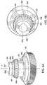
- FIGS. 4A and 4B respectively illustrate front and overhead perspective views of the drive sub-assembly 150, according to aspects of the present disclosure.
- the drive sub-assembly 150 may be assembled into a single part that may be installed in the drive system 100, as well as removed from the drive system 100 and replaced.
- the drive sub-assembly 150 may include the gear 200, the hub 202, and the first inner race 204a and first rollers 204b of the first output bearing assembly 204 assembled into the single part to be installed in the drive system 100, according to an aspect of the present disclosure.
- the first output bearing assembly 204 includes a first cage or separator 400 which holds the first rollers 204b.
- a key recess 402 may be formed in portions of the inner hub surface 202j along the longitudinal axis A corresponding to the second outer hub surface 202c and the hub outer recess 202e. According to an aspect of the present disclosure, the key recess 402 may extend to the first end face 202f of the hub 202.
- the key recess 402 may correspond to a shape of a keyed portion (not shown) of the output shaft 102. The keyed portion of the output shaft 102 may fit into the key recess 402 and operatively engage (e.g.
- the drive sub-assembly 150 of FIGS. 4A and 4B may include one more components not shown including the second seal 216, the spacer 218, and one or more components of the second output bearing assembly 220.
- the drive sub-assembly 150 of FIGS. 4A and 4B as the single assembled part may include the second seal 216 positioned within inner hub recess 202i, and the spacer 218 positioned between second end face 202g and the second outer race 212c which is fixed to the inner gear surface 200b.
- the inner gear surface 200b may overlap at least a portion the second end face 202g, the second outer race 212c, and the spacer 218 along the longitudinal axis A.
- spacers of different annular dimensions may be provided for the spacer 218 according the present disclosure.
- the spacer 218 as applied in the drive sub-assembly 150 of FIGS. 4A and 4B may cover all or a portion of a radial space between the inner gear surface 200b and the second outer surface 126b of the second shaft housing 126.
- the spacer 218 may cover all of the radial space discussed above, and hold the second seal 216 within the inner hub recess 202i when the drive sub-assembly is not installed in the drive system 100.
- FIG. 5 illustrates an exploded view of the drive sub-assembly 150 and a portion of the housing assembly 104 including the second shaft housing 126, according to an aspect of the present disclosure.
- the second seal 216 may be placed in the inner hub recess 202i and the spacer 218 may be placed inwardly of the mounting surface 200a and between at least the second outer race 212c and the second end face 202g ( FIG. 2 ) of the hub 202.
- the hub 202 may be attached to the output gear 200 by the fasteners 201 which extend through first bores 500 formed in the hub 202 and second bores 502 formed in the gear 200.
- At least the second bores 502 may include corresponding threaded surfaces to receive and secure the fasteners 201 in order to secure the gear 200 to the hub 202.
- Prior to or after the gear 200 being attached to the hub 202, at least the first inner race 204a, first rollers 204b, and first cage or separator 400 may be mounted and attached to the second hub outer surface 202c/shoulder 202d.
- the second inner race 220a, the second rollers 220b, and a second cage or separator 504 which holds the second rollers 220b may be mounted and attached to the first outer surface 126a of the second shaft housing 126.
- the assembled drive sub-assembly 150 including the output gear 200 and the hub 202 may be mounted on the second shaft housing 126 such that the second rollers 220b engage the second outer race 220c located on the gear inner surface 200b.
- first inner race 204a, the first rollers 204b, and first cage or separator 400 may be positioned on the hub 200 before or after a sub-assembly of the hub 202 and the output gear 200 (including at least the second outer race 220c) is positioned on the second shaft housing 126, which may then be followed by the placement of the first seal 206 around the hub outer recess 202e.
- the first housing 104a may be mounted on the second housing 104b by aligning an opening defined by the first shaft housing 124 with the hub 202 of the drive sub-assembly 150 as illustrated in FIGS. 1 and 2 .
- the first outer race 204c of the first output bearing assembly 204 will engage the first rollers 204b, and the first seal 206 will engage an inner surface of the first shaft housing 124 as illustrated in FIG. 2 .
- the output shaft 102 may be inserted through the bore 134 and passage defined by the second shaft housing 126 and the inner hub surface 202j, thereby engaging the key recess 402 of the hub 202 illustrated in FIG. 4B .
- the thrust plate 132 illustrated in FIGS. 1 and 2 may be secured to the end of the output shaft 102 via bolts or other fasteners causing the output shaft 102 to be held in place within the drive system 100. Subsequent to the securement of the thrust plate 132, the cover 128 may be fixed on to the first shaft housing 124.
Landscapes
- Engineering & Computer Science (AREA)
- General Engineering & Computer Science (AREA)
- Mechanical Engineering (AREA)
- Chemical & Material Sciences (AREA)
- Chemical Kinetics & Catalysis (AREA)
- General Details Of Gearings (AREA)
- Mounting Of Bearings Or Others (AREA)
- Rolling Contact Bearings (AREA)
Applications Claiming Priority (1)
| Application Number | Priority Date | Filing Date | Title |
|---|---|---|---|
| US15/253,131 US10508727B2 (en) | 2016-08-31 | 2016-08-31 | Drive system and drive sub-assembly for driving a shaft |
Publications (2)
| Publication Number | Publication Date |
|---|---|
| EP3290732A1 EP3290732A1 (en) | 2018-03-07 |
| EP3290732B1 true EP3290732B1 (en) | 2020-08-05 |
Family
ID=59829139
Family Applications (1)
| Application Number | Title | Priority Date | Filing Date |
|---|---|---|---|
| EP17188301.0A Active EP3290732B1 (en) | 2016-08-31 | 2017-08-29 | Drive system and drive sub-assembly for driving a shaft |
Country Status (8)
| Country | Link |
|---|---|
| US (1) | US10508727B2 (da) |
| EP (1) | EP3290732B1 (da) |
| CN (1) | CN107795638B (da) |
| AU (1) | AU2017210479B2 (da) |
| CA (1) | CA2975481C (da) |
| DK (1) | DK3290732T3 (da) |
| ES (1) | ES2828685T3 (da) |
| SG (1) | SG10201707080XA (da) |
Families Citing this family (10)
| Publication number | Priority date | Publication date | Assignee | Title |
|---|---|---|---|---|
| EP3421194A4 (en) * | 2016-02-25 | 2019-09-11 | Daihen Corporation | DRIVE DEVICE |
| JP6679380B2 (ja) * | 2016-03-30 | 2020-04-15 | Ntn株式会社 | 電動アクチュエータ |
| CN109311150B (zh) * | 2016-07-07 | 2020-09-01 | Abb瑞士股份有限公司 | 用于并联运动机器人的基座 |
| CN110762184A (zh) * | 2018-07-27 | 2020-02-07 | 江苏泰隆减速机股份有限公司 | 一种有色金属金加工行业用可移动开卷减速机 |
| US10823553B1 (en) * | 2019-07-01 | 2020-11-03 | Snap-On Incorporated | Apparatus with component aligner |
| US11010908B2 (en) | 2019-07-01 | 2021-05-18 | Snap-On Incorporated | Apparatus with component aligner |
| US11555743B2 (en) | 2019-07-01 | 2023-01-17 | Snap-On Incorporated | Method and system for calibrating imaging system |
| US11709099B2 (en) | 2019-07-01 | 2023-07-25 | Snap-On Incorporated | Method and system for calibrating imaging system |
| US10781852B1 (en) * | 2019-10-21 | 2020-09-22 | GM Global Technology Operations LLC | Modular labyrinth bearing assembly |
| US11578760B1 (en) * | 2021-07-30 | 2023-02-14 | Rivian Ip Holdings, Llc | Input gear assembly with pilot regions on shaft and inner bearing race |
Family Cites Families (38)
| Publication number | Priority date | Publication date | Assignee | Title |
|---|---|---|---|---|
| DE7736479U1 (da) | Prometheus Maschinenfabrik Gmbh, 1000 Berlin | |||
| US4025136A (en) * | 1975-11-03 | 1977-05-24 | Allis-Chalmers Corporation | Multiple bearing adjusting device |
| DE3044050C2 (de) * | 1980-11-22 | 1982-10-07 | Zahnradfabrik Friedrichshafen Ag, 7990 Friedrichshafen | Haltevorrichtung für ein Lager |
| US5211488A (en) * | 1990-03-19 | 1993-05-18 | Regal Beloit Corporation | Single tapered bushing for shaft mount |
| JPH05118495A (ja) * | 1991-10-25 | 1993-05-14 | Mitsubishi Heavy Ind Ltd | 歯車箱の潤滑装置 |
| US5567056A (en) * | 1994-09-29 | 1996-10-22 | General Motors Corporation | Turbocharger drive and planet bearing therefor |
| JP3166515B2 (ja) * | 1994-11-11 | 2001-05-14 | 三菱自動車工業株式会社 | 車両用リダクション装置 |
| US5653658A (en) * | 1996-01-30 | 1997-08-05 | Caterpillar Inc. | Bearing lubrication system |
| US5810116A (en) * | 1997-06-04 | 1998-09-22 | New Venture Gear, Inc. | Bearing lubrication mechanism |
| US6058793A (en) * | 1999-01-19 | 2000-05-09 | Chemineer, Inc. | Parallel shaft speed reducer with sump and dry well |
| DE10046719A1 (de) * | 2000-09-21 | 2002-04-11 | Ina Schaeffler Kg | Zahnräderwechselgetriebe |
| DE60239630D1 (de) * | 2001-11-08 | 2011-05-12 | Jtekt Corp | Lagervorrichtung zur abstützung einer ritzelwelle |
| US6708578B2 (en) * | 2002-03-07 | 2004-03-23 | General Motors Corporation | Transfer gear assembly for transmission |
| US6715913B2 (en) * | 2002-03-29 | 2004-04-06 | Spx Corporation | Shaft bearing support method and apparatus |
| US6929402B1 (en) * | 2002-04-11 | 2005-08-16 | Morgan Construction Company | Journal bearing and thrust pad assembly |
| JP2004239320A (ja) | 2003-02-04 | 2004-08-26 | Hitachi Constr Mach Co Ltd | 減速装置 |
| US6852058B2 (en) * | 2003-03-04 | 2005-02-08 | Arvinmeritor Technology, Llc | Hollow pinion support |
| US7393141B2 (en) * | 2003-09-22 | 2008-07-01 | The Timken Company | Bearing arrangement for a vehicle differential |
| US7273132B2 (en) * | 2003-10-15 | 2007-09-25 | Weasler Engineering, Inc. | Method and apparatus for lubricating bearings on a vertical shaft in a gearbox |
| DE102006051817A1 (de) * | 2006-11-03 | 2008-05-08 | Schaeffler Kg | Lageranordnung zur drehbaren Lagerung eines Planetenrades auf einem Planetenträger |
| FR2910948B1 (fr) * | 2006-12-27 | 2009-02-13 | Hispano Suiza Sa | Engrenage a protection de surcouple integree |
| US8480531B2 (en) * | 2007-02-02 | 2013-07-09 | Arvinmeritor Technology, Llc | Differential assembly with inverted bearing |
| US8689657B2 (en) * | 2008-07-09 | 2014-04-08 | Mclaren Performance Technologies, Inc. | Axially compact support for a gear within a gearbox |
| JP2010255778A (ja) * | 2009-04-27 | 2010-11-11 | Nsk Ltd | ラジアルニードル軸受 |
| US8172716B2 (en) * | 2009-06-25 | 2012-05-08 | United Technologies Corporation | Epicyclic gear system with superfinished journal bearing |
| DE102010055411A1 (de) * | 2010-12-21 | 2012-06-21 | Schaeffler Technologies Gmbh & Co. Kg | Anordnung zur Abstützung eines Eingangsrads eines Getriebes |
| WO2012086036A1 (ja) * | 2010-12-22 | 2012-06-28 | トヨタ自動車株式会社 | 車両用動力伝達装置 |
| US8641574B2 (en) * | 2011-02-24 | 2014-02-04 | Ford Global Technologies, Llc | Transfer shaft support |
| US8702553B2 (en) * | 2011-02-24 | 2014-04-22 | Ford Global Technologies, Llc | Transfer shaft support |
| US20140150589A1 (en) * | 2012-12-05 | 2014-06-05 | One John Deere Place | System for lubricating input shaft spline of final drive transmission |
| AT513613B1 (de) * | 2013-02-08 | 2014-06-15 | Miba Sinter Austria Gmbh | Zahnradanordnung |
| JP6236733B2 (ja) * | 2013-06-11 | 2017-11-29 | 株式会社リコー | 伝動機構、駆動機構及び画像形成装置 |
| KR101506090B1 (ko) * | 2013-10-16 | 2015-03-25 | 현대다이모스(주) | 수동 변속기의 파일럿 베어링 윤활 장치 |
| US9784365B2 (en) * | 2014-01-23 | 2017-10-10 | Pratt & Whitney Canada Corp. | Variable vane actuating system |
| FR3018860B1 (fr) * | 2014-03-21 | 2021-10-15 | Hispano Suiza Sa | Relais d'accessoires pour moteur a turbine a gaz |
| US9709136B2 (en) * | 2014-06-10 | 2017-07-18 | The Boeing Company | Aircraft and planetary gear systems |
| JP6537229B2 (ja) * | 2014-07-31 | 2019-07-03 | キヤノン株式会社 | 駆動伝達機構および画像形成装置 |
| DE112015006013B4 (de) * | 2015-01-14 | 2019-04-04 | Honda Motor Co., Ltd. | Getriebe |
-
2016
- 2016-08-31 US US15/253,131 patent/US10508727B2/en active Active
-
2017
- 2017-07-31 AU AU2017210479A patent/AU2017210479B2/en active Active
- 2017-08-03 CA CA2975481A patent/CA2975481C/en active Active
- 2017-08-29 EP EP17188301.0A patent/EP3290732B1/en active Active
- 2017-08-29 ES ES17188301T patent/ES2828685T3/es active Active
- 2017-08-29 DK DK17188301.0T patent/DK3290732T3/da active
- 2017-08-30 SG SG10201707080XA patent/SG10201707080XA/en unknown
- 2017-08-30 CN CN201710766026.0A patent/CN107795638B/zh active Active
Non-Patent Citations (1)
| Title |
|---|
| None * |
Also Published As
| Publication number | Publication date |
|---|---|
| ES2828685T3 (es) | 2021-05-27 |
| AU2017210479A1 (en) | 2018-03-15 |
| EP3290732A1 (en) | 2018-03-07 |
| US10508727B2 (en) | 2019-12-17 |
| CA2975481A1 (en) | 2018-02-28 |
| DK3290732T3 (da) | 2020-11-09 |
| CA2975481C (en) | 2025-09-23 |
| CN107795638B (zh) | 2022-07-22 |
| US20180058567A1 (en) | 2018-03-01 |
| CN107795638A (zh) | 2018-03-13 |
| SG10201707080XA (en) | 2018-03-28 |
| AU2017210479B2 (en) | 2022-01-27 |
| BR102017018687A2 (pt) | 2018-03-20 |
Similar Documents
| Publication | Publication Date | Title |
|---|---|---|
| EP3290732B1 (en) | Drive system and drive sub-assembly for driving a shaft | |
| CN106151474B (zh) | 干井轴组件 | |
| US8398310B2 (en) | Self aligning bearing and seal assembly | |
| US5897214A (en) | Method and apparatus for securing a rotary member to a stationary shaft | |
| EP3359850B1 (en) | Method for installing a transmission and shaftseat applied thereby | |
| US10428801B2 (en) | Wind power generation device | |
| US20220371136A1 (en) | Rotary table device | |
| US9200609B2 (en) | Torque transmission mechanism | |
| US6599052B1 (en) | Hub and shaft coupling system | |
| US20060035746A1 (en) | Drive shaft assembly and method of separation | |
| US12366282B2 (en) | Gear motor including an electric motor and a gearbox | |
| US20160032899A1 (en) | One-way clutch for wind power generation device, and wind power generation device | |
| US12021435B2 (en) | Disconnect bearing and input seal for a variable frequency starter generator | |
| CA2969760C (en) | Bearing isolator seal with enhanced rotor drive coupling | |
| EP3693579B1 (en) | Starter locking assembly and method | |
| US20150014119A1 (en) | Torque Transmission Mechanism | |
| EP2824317A1 (en) | Torque transmission mechanism | |
| US20260049639A1 (en) | Drive assembly and vehicle having such a drive assembly of this type | |
| US3013848A (en) | Bearing assembly | |
| EP3096016B1 (en) | Volumetric pump |
Legal Events
| Date | Code | Title | Description |
|---|---|---|---|
| PUAI | Public reference made under article 153(3) epc to a published international application that has entered the european phase |
Free format text: ORIGINAL CODE: 0009012 |
|
| STAA | Information on the status of an ep patent application or granted ep patent |
Free format text: STATUS: THE APPLICATION HAS BEEN PUBLISHED |
|
| AK | Designated contracting states |
Kind code of ref document: A1 Designated state(s): AL AT BE BG CH CY CZ DE DK EE ES FI FR GB GR HR HU IE IS IT LI LT LU LV MC MK MT NL NO PL PT RO RS SE SI SK SM TR |
|
| AX | Request for extension of the european patent |
Extension state: BA ME |
|
| STAA | Information on the status of an ep patent application or granted ep patent |
Free format text: STATUS: REQUEST FOR EXAMINATION WAS MADE |
|
| 17P | Request for examination filed |
Effective date: 20180817 |
|
| RBV | Designated contracting states (corrected) |
Designated state(s): AL AT BE BG CH CY CZ DE DK EE ES FI FR GB GR HR HU IE IS IT LI LT LU LV MC MK MT NL NO PL PT RO RS SE SI SK SM TR |
|
| GRAP | Despatch of communication of intention to grant a patent |
Free format text: ORIGINAL CODE: EPIDOSNIGR1 |
|
| STAA | Information on the status of an ep patent application or granted ep patent |
Free format text: STATUS: GRANT OF PATENT IS INTENDED |
|
| RIC1 | Information provided on ipc code assigned before grant |
Ipc: F16H 57/021 20120101ALI20200122BHEP Ipc: F16C 33/58 20060101ALN20200122BHEP Ipc: F16C 25/06 20060101ALI20200122BHEP Ipc: F16H 57/00 20120101ALI20200122BHEP Ipc: F16H 57/02 20120101ALI20200122BHEP Ipc: B01F 15/00 20060101ALN20200122BHEP Ipc: F16H 57/04 20100101ALI20200122BHEP Ipc: F16C 23/06 20060101ALI20200122BHEP Ipc: F16C 19/38 20060101ALN20200122BHEP Ipc: F16C 35/073 20060101AFI20200122BHEP |
|
| INTG | Intention to grant announced |
Effective date: 20200220 |
|
| GRAS | Grant fee paid |
Free format text: ORIGINAL CODE: EPIDOSNIGR3 |
|
| GRAA | (expected) grant |
Free format text: ORIGINAL CODE: 0009210 |
|
| STAA | Information on the status of an ep patent application or granted ep patent |
Free format text: STATUS: THE PATENT HAS BEEN GRANTED |
|
| AK | Designated contracting states |
Kind code of ref document: B1 Designated state(s): AL AT BE BG CH CY CZ DE DK EE ES FI FR GB GR HR HU IE IS IT LI LT LU LV MC MK MT NL NO PL PT RO RS SE SI SK SM TR |
|
| REG | Reference to a national code |
Ref country code: GB Ref legal event code: FG4D |
|
| REG | Reference to a national code |
Ref country code: CH Ref legal event code: EP |
|
| REG | Reference to a national code |
Ref country code: AT Ref legal event code: REF Ref document number: 1299116 Country of ref document: AT Kind code of ref document: T Effective date: 20200815 |
|
| REG | Reference to a national code |
Ref country code: DE Ref legal event code: R096 Ref document number: 602017020908 Country of ref document: DE |
|
| REG | Reference to a national code |
Ref country code: IE Ref legal event code: FG4D |
|
| REG | Reference to a national code |
Ref country code: FI Ref legal event code: FGE |
|
| REG | Reference to a national code |
Ref country code: DK Ref legal event code: T3 Effective date: 20201102 |
|
| REG | Reference to a national code |
Ref country code: SE Ref legal event code: TRGR |
|
| REG | Reference to a national code |
Ref country code: NL Ref legal event code: FP |
|
| REG | Reference to a national code |
Ref country code: LT Ref legal event code: MG4D |
|
| REG | Reference to a national code |
Ref country code: CH Ref legal event code: NV Representative=s name: SERVOPATENT GMBH, CH Ref country code: AT Ref legal event code: MK05 Ref document number: 1299116 Country of ref document: AT Kind code of ref document: T Effective date: 20200805 |
|
| PG25 | Lapsed in a contracting state [announced via postgrant information from national office to epo] |
Ref country code: PT Free format text: LAPSE BECAUSE OF FAILURE TO SUBMIT A TRANSLATION OF THE DESCRIPTION OR TO PAY THE FEE WITHIN THE PRESCRIBED TIME-LIMIT Effective date: 20201207 Ref country code: HR Free format text: LAPSE BECAUSE OF FAILURE TO SUBMIT A TRANSLATION OF THE DESCRIPTION OR TO PAY THE FEE WITHIN THE PRESCRIBED TIME-LIMIT Effective date: 20200805 Ref country code: AT Free format text: LAPSE BECAUSE OF FAILURE TO SUBMIT A TRANSLATION OF THE DESCRIPTION OR TO PAY THE FEE WITHIN THE PRESCRIBED TIME-LIMIT Effective date: 20200805 Ref country code: LT Free format text: LAPSE BECAUSE OF FAILURE TO SUBMIT A TRANSLATION OF THE DESCRIPTION OR TO PAY THE FEE WITHIN THE PRESCRIBED TIME-LIMIT Effective date: 20200805 Ref country code: GR Free format text: LAPSE BECAUSE OF FAILURE TO SUBMIT A TRANSLATION OF THE DESCRIPTION OR TO PAY THE FEE WITHIN THE PRESCRIBED TIME-LIMIT Effective date: 20201106 Ref country code: NO Free format text: LAPSE BECAUSE OF FAILURE TO SUBMIT A TRANSLATION OF THE DESCRIPTION OR TO PAY THE FEE WITHIN THE PRESCRIBED TIME-LIMIT Effective date: 20201105 Ref country code: BG Free format text: LAPSE BECAUSE OF FAILURE TO SUBMIT A TRANSLATION OF THE DESCRIPTION OR TO PAY THE FEE WITHIN THE PRESCRIBED TIME-LIMIT Effective date: 20201105 |
|
| PG25 | Lapsed in a contracting state [announced via postgrant information from national office to epo] |
Ref country code: IS Free format text: LAPSE BECAUSE OF FAILURE TO SUBMIT A TRANSLATION OF THE DESCRIPTION OR TO PAY THE FEE WITHIN THE PRESCRIBED TIME-LIMIT Effective date: 20201205 Ref country code: LV Free format text: LAPSE BECAUSE OF FAILURE TO SUBMIT A TRANSLATION OF THE DESCRIPTION OR TO PAY THE FEE WITHIN THE PRESCRIBED TIME-LIMIT Effective date: 20200805 Ref country code: PL Free format text: LAPSE BECAUSE OF FAILURE TO SUBMIT A TRANSLATION OF THE DESCRIPTION OR TO PAY THE FEE WITHIN THE PRESCRIBED TIME-LIMIT Effective date: 20200805 Ref country code: RS Free format text: LAPSE BECAUSE OF FAILURE TO SUBMIT A TRANSLATION OF THE DESCRIPTION OR TO PAY THE FEE WITHIN THE PRESCRIBED TIME-LIMIT Effective date: 20200805 |
|
| PG25 | Lapsed in a contracting state [announced via postgrant information from national office to epo] |
Ref country code: SM Free format text: LAPSE BECAUSE OF FAILURE TO SUBMIT A TRANSLATION OF THE DESCRIPTION OR TO PAY THE FEE WITHIN THE PRESCRIBED TIME-LIMIT Effective date: 20200805 Ref country code: EE Free format text: LAPSE BECAUSE OF FAILURE TO SUBMIT A TRANSLATION OF THE DESCRIPTION OR TO PAY THE FEE WITHIN THE PRESCRIBED TIME-LIMIT Effective date: 20200805 Ref country code: LU Free format text: LAPSE BECAUSE OF NON-PAYMENT OF DUE FEES Effective date: 20200829 Ref country code: RO Free format text: LAPSE BECAUSE OF FAILURE TO SUBMIT A TRANSLATION OF THE DESCRIPTION OR TO PAY THE FEE WITHIN THE PRESCRIBED TIME-LIMIT Effective date: 20200805 Ref country code: CZ Free format text: LAPSE BECAUSE OF FAILURE TO SUBMIT A TRANSLATION OF THE DESCRIPTION OR TO PAY THE FEE WITHIN THE PRESCRIBED TIME-LIMIT Effective date: 20200805 |
|
| REG | Reference to a national code |
Ref country code: DE Ref legal event code: R097 Ref document number: 602017020908 Country of ref document: DE |
|
| REG | Reference to a national code |
Ref country code: BE Ref legal event code: MM Effective date: 20200831 |
|
| REG | Reference to a national code |
Ref country code: ES Ref legal event code: FG2A Ref document number: 2828685 Country of ref document: ES Kind code of ref document: T3 Effective date: 20210527 |
|
| PG25 | Lapsed in a contracting state [announced via postgrant information from national office to epo] |
Ref country code: MC Free format text: LAPSE BECAUSE OF FAILURE TO SUBMIT A TRANSLATION OF THE DESCRIPTION OR TO PAY THE FEE WITHIN THE PRESCRIBED TIME-LIMIT Effective date: 20200805 Ref country code: AL Free format text: LAPSE BECAUSE OF FAILURE TO SUBMIT A TRANSLATION OF THE DESCRIPTION OR TO PAY THE FEE WITHIN THE PRESCRIBED TIME-LIMIT Effective date: 20200805 |
|
| PLBE | No opposition filed within time limit |
Free format text: ORIGINAL CODE: 0009261 |
|
| STAA | Information on the status of an ep patent application or granted ep patent |
Free format text: STATUS: NO OPPOSITION FILED WITHIN TIME LIMIT |
|
| PG25 | Lapsed in a contracting state [announced via postgrant information from national office to epo] |
Ref country code: SK Free format text: LAPSE BECAUSE OF FAILURE TO SUBMIT A TRANSLATION OF THE DESCRIPTION OR TO PAY THE FEE WITHIN THE PRESCRIBED TIME-LIMIT Effective date: 20200805 |
|
| 26N | No opposition filed |
Effective date: 20210507 |
|
| PG25 | Lapsed in a contracting state [announced via postgrant information from national office to epo] |
Ref country code: BE Free format text: LAPSE BECAUSE OF NON-PAYMENT OF DUE FEES Effective date: 20200831 Ref country code: SI Free format text: LAPSE BECAUSE OF FAILURE TO SUBMIT A TRANSLATION OF THE DESCRIPTION OR TO PAY THE FEE WITHIN THE PRESCRIBED TIME-LIMIT Effective date: 20200805 |
|
| PG25 | Lapsed in a contracting state [announced via postgrant information from national office to epo] |
Ref country code: TR Free format text: LAPSE BECAUSE OF FAILURE TO SUBMIT A TRANSLATION OF THE DESCRIPTION OR TO PAY THE FEE WITHIN THE PRESCRIBED TIME-LIMIT Effective date: 20200805 Ref country code: MT Free format text: LAPSE BECAUSE OF FAILURE TO SUBMIT A TRANSLATION OF THE DESCRIPTION OR TO PAY THE FEE WITHIN THE PRESCRIBED TIME-LIMIT Effective date: 20200805 Ref country code: CY Free format text: LAPSE BECAUSE OF FAILURE TO SUBMIT A TRANSLATION OF THE DESCRIPTION OR TO PAY THE FEE WITHIN THE PRESCRIBED TIME-LIMIT Effective date: 20200805 |
|
| PG25 | Lapsed in a contracting state [announced via postgrant information from national office to epo] |
Ref country code: MK Free format text: LAPSE BECAUSE OF FAILURE TO SUBMIT A TRANSLATION OF THE DESCRIPTION OR TO PAY THE FEE WITHIN THE PRESCRIBED TIME-LIMIT Effective date: 20200805 |
|
| PGFP | Annual fee paid to national office [announced via postgrant information from national office to epo] |
Ref country code: NL Payment date: 20240826 Year of fee payment: 8 |
|
| PGFP | Annual fee paid to national office [announced via postgrant information from national office to epo] |
Ref country code: IE Payment date: 20240827 Year of fee payment: 8 |
|
| PGFP | Annual fee paid to national office [announced via postgrant information from national office to epo] |
Ref country code: DK Payment date: 20240826 Year of fee payment: 8 |
|
| PGFP | Annual fee paid to national office [announced via postgrant information from national office to epo] |
Ref country code: GB Payment date: 20240827 Year of fee payment: 8 |
|
| PGFP | Annual fee paid to national office [announced via postgrant information from national office to epo] |
Ref country code: CH Payment date: 20240903 Year of fee payment: 8 Ref country code: ES Payment date: 20240902 Year of fee payment: 8 |
|
| PGFP | Annual fee paid to national office [announced via postgrant information from national office to epo] |
Ref country code: IT Payment date: 20240822 Year of fee payment: 8 Ref country code: SE Payment date: 20240827 Year of fee payment: 8 |
|
| PGFP | Annual fee paid to national office [announced via postgrant information from national office to epo] |
Ref country code: FI Payment date: 20250825 Year of fee payment: 9 |
|
| PGFP | Annual fee paid to national office [announced via postgrant information from national office to epo] |
Ref country code: DE Payment date: 20250827 Year of fee payment: 9 |
|
| PGFP | Annual fee paid to national office [announced via postgrant information from national office to epo] |
Ref country code: FR Payment date: 20250825 Year of fee payment: 9 |
|
| REG | Reference to a national code |
Ref country code: DK Ref legal event code: EBP Effective date: 20250831 |
|
| REG | Reference to a national code |
Ref country code: CH Ref legal event code: H13 Free format text: ST27 STATUS EVENT CODE: U-0-0-H10-H13 (AS PROVIDED BY THE NATIONAL OFFICE) Effective date: 20260324 |
|
| REG | Reference to a national code |
Ref country code: NL Ref legal event code: MM Effective date: 20250901 |
|
| PG25 | Lapsed in a contracting state [announced via postgrant information from national office to epo] |
Ref country code: CH Free format text: LAPSE BECAUSE OF NON-PAYMENT OF DUE FEES Effective date: 20250831 |