EP3290785B1 - Stirnlampe, die mit einem starren oder halbstarren band versehen ist - Google Patents
Stirnlampe, die mit einem starren oder halbstarren band versehen ist Download PDFInfo
- Publication number
- EP3290785B1 EP3290785B1 EP17188218.6A EP17188218A EP3290785B1 EP 3290785 B1 EP3290785 B1 EP 3290785B1 EP 17188218 A EP17188218 A EP 17188218A EP 3290785 B1 EP3290785 B1 EP 3290785B1
- Authority
- EP
- European Patent Office
- Prior art keywords
- rigid
- semi
- lamp
- attached
- strip
- Prior art date
- Legal status (The legal status is an assumption and is not a legal conclusion. Google has not performed a legal analysis and makes no representation as to the accuracy of the status listed.)
- Active
Links
Images











Classifications
-
- F—MECHANICAL ENGINEERING; LIGHTING; HEATING; WEAPONS; BLASTING
- F21—LIGHTING
- F21L—LIGHTING DEVICES OR SYSTEMS THEREOF, BEING PORTABLE OR SPECIALLY ADAPTED FOR TRANSPORTATION
- F21L4/00—Electric lighting devices with self-contained electric batteries or cells
-
- F—MECHANICAL ENGINEERING; LIGHTING; HEATING; WEAPONS; BLASTING
- F21—LIGHTING
- F21V—FUNCTIONAL FEATURES OR DETAILS OF LIGHTING DEVICES OR SYSTEMS THEREOF; STRUCTURAL COMBINATIONS OF LIGHTING DEVICES WITH OTHER ARTICLES, NOT OTHERWISE PROVIDED FOR
- F21V21/00—Supporting, suspending, or attaching arrangements for lighting devices; Hand grips
- F21V21/08—Devices for easy attachment to any desired place, e.g. clip, clamp, magnet
- F21V21/084—Head fittings
-
- F—MECHANICAL ENGINEERING; LIGHTING; HEATING; WEAPONS; BLASTING
- F21—LIGHTING
- F21L—LIGHTING DEVICES OR SYSTEMS THEREOF, BEING PORTABLE OR SPECIALLY ADAPTED FOR TRANSPORTATION
- F21L4/00—Electric lighting devices with self-contained electric batteries or cells
- F21L4/02—Electric lighting devices with self-contained electric batteries or cells characterised by the provision of two or more light sources
-
- F—MECHANICAL ENGINEERING; LIGHTING; HEATING; WEAPONS; BLASTING
- F21—LIGHTING
- F21S—NON-PORTABLE LIGHTING DEVICES; SYSTEMS THEREOF; VEHICLE LIGHTING DEVICES SPECIALLY ADAPTED FOR VEHICLE EXTERIORS
- F21S6/00—Lighting devices intended to be free-standing
- F21S6/002—Table lamps, e.g. for ambient lighting
-
- F—MECHANICAL ENGINEERING; LIGHTING; HEATING; WEAPONS; BLASTING
- F21—LIGHTING
- F21V—FUNCTIONAL FEATURES OR DETAILS OF LIGHTING DEVICES OR SYSTEMS THEREOF; STRUCTURAL COMBINATIONS OF LIGHTING DEVICES WITH OTHER ARTICLES, NOT OTHERWISE PROVIDED FOR
- F21V21/00—Supporting, suspending, or attaching arrangements for lighting devices; Hand grips
- F21V21/14—Adjustable mountings
- F21V21/30—Pivoted housings or frames
-
- F—MECHANICAL ENGINEERING; LIGHTING; HEATING; WEAPONS; BLASTING
- F21—LIGHTING
- F21V—FUNCTIONAL FEATURES OR DETAILS OF LIGHTING DEVICES OR SYSTEMS THEREOF; STRUCTURAL COMBINATIONS OF LIGHTING DEVICES WITH OTHER ARTICLES, NOT OTHERWISE PROVIDED FOR
- F21V23/00—Arrangement of electric circuit elements in or on lighting devices
- F21V23/04—Arrangement of electric circuit elements in or on lighting devices the elements being switches
-
- F—MECHANICAL ENGINEERING; LIGHTING; HEATING; WEAPONS; BLASTING
- F21—LIGHTING
- F21V—FUNCTIONAL FEATURES OR DETAILS OF LIGHTING DEVICES OR SYSTEMS THEREOF; STRUCTURAL COMBINATIONS OF LIGHTING DEVICES WITH OTHER ARTICLES, NOT OTHERWISE PROVIDED FOR
- F21V23/00—Arrangement of electric circuit elements in or on lighting devices
- F21V23/04—Arrangement of electric circuit elements in or on lighting devices the elements being switches
- F21V23/0414—Arrangement of electric circuit elements in or on lighting devices the elements being switches specially adapted to be used with portable lighting devices
-
- G—PHYSICS
- G02—OPTICS
- G02B—OPTICAL ELEMENTS, SYSTEMS OR APPARATUS
- G02B6/00—Light guides; Structural details of arrangements comprising light guides and other optical elements, e.g. couplings
- G02B6/0001—Light guides; Structural details of arrangements comprising light guides and other optical elements, e.g. couplings specially adapted for lighting devices or systems
- G02B6/0005—Light guides; Structural details of arrangements comprising light guides and other optical elements, e.g. couplings specially adapted for lighting devices or systems the light guides being of the fibre type
-
- F—MECHANICAL ENGINEERING; LIGHTING; HEATING; WEAPONS; BLASTING
- F21—LIGHTING
- F21V—FUNCTIONAL FEATURES OR DETAILS OF LIGHTING DEVICES OR SYSTEMS THEREOF; STRUCTURAL COMBINATIONS OF LIGHTING DEVICES WITH OTHER ARTICLES, NOT OTHERWISE PROVIDED FOR
- F21V21/00—Supporting, suspending, or attaching arrangements for lighting devices; Hand grips
- F21V21/14—Adjustable mountings
- F21V21/145—Adjustable mountings for portable lighting devices
-
- F—MECHANICAL ENGINEERING; LIGHTING; HEATING; WEAPONS; BLASTING
- F21—LIGHTING
- F21Y—INDEXING SCHEME ASSOCIATED WITH SUBCLASSES F21K, F21L, F21S and F21V, RELATING TO THE FORM OR THE KIND OF THE LIGHT SOURCES OR OF THE COLOUR OF THE LIGHT EMITTED
- F21Y2101/00—Point-like light sources
-
- F—MECHANICAL ENGINEERING; LIGHTING; HEATING; WEAPONS; BLASTING
- F21—LIGHTING
- F21Y—INDEXING SCHEME ASSOCIATED WITH SUBCLASSES F21K, F21L, F21S and F21V, RELATING TO THE FORM OR THE KIND OF THE LIGHT SOURCES OR OF THE COLOUR OF THE LIGHT EMITTED
- F21Y2115/00—Light-generating elements of semiconductor light sources
- F21Y2115/10—Light-emitting diodes [LED]
Definitions
- the present invention relates to the field of portable electric lamps and in particular a headlamp with a rigid or semi-rigid headband.
- the headlamps originally used by minors, are a great success in the field of recreation, including caving and hiking. They also feature prominently in the panoply of professional tools.
- a headlamp comprises the combination of a lamp and a headband which is elastic, and which ensures the maintenance of the lamp on the head of a user with optimum comfort.
- the present invention is intended to provide a real "break", figuratively speaking, in the design of a strip ensuring the maintenance of a headlamp.
- the patent CN103216793 describes another example of a headlamp.
- the patent FR2971037 describes a portable electric lighting lamp with improved fixation.
- the present invention aims to provide a headlamp with a new type of rigid / semi-rigid headband for wide adjustment possibilities on various user heads, or even a helmet.
- Another object of the present invention is to provide a headlamp with a headband having a new style and new ergonomics, closer to the morphology of the user and ensuring greater comfort.
- This unique structure of the band which presents itself with a certain capacity of deformation while maintaining a constant length, offers a new aesthetic, a new style as well as new functional possibilities.
- the new headband has an exceptional ability of adjustment since it allows variations of 19cm of perimeters for the different heads of users, and even a construction helmet.
- the strip is configured to allow the attachment, at the rear, of a battery for the power supply of the lamp.
- the headband may include, at the rear, a rear light.
- the strip may have a tubular section so as to integrate a plurality of electrical conductors for the power supply of the lamp and / or the control of the lamp functions.
- the strip may also integrate one or more optical fibers for conveying backwards, forwards and even laterally a fraction of the light beam generated by said lamp.
- the rigid elements of the banner with one or more switches and / or display for controlling the functionality of the lamp.
- the lamp attached to the front of the headband and is provided with at least one pivot for pivoting on said front portion of said headband, and configured to allow a pivot of at least 180 degrees.
- the pivot makes it possible to adjust the light beam of the lamp for horizontal illumination, but also downwards when the lamp is worn around the neck.
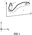
- the figure 1 illustrates the three-dimensional plot of a first embodiment of a rigid / semi-rigid strip 10 of a headlamp which offers three-dimensional deformation possibilities at constant length, in space and in particular in three planes xz, xy and yz.
- the strip is in the form of a tubular support, symmetrical with respect to a plane (x, z) approximately corresponding to a median sagittal plane for the lamp holder (and shown in FIG. figure 2 ).
- the first embodiment which is schematized in the figure 1 shows a rigid / semi-rigid (but deformable) front part 1 on which the lamp will be fixed, and which is approximately located in a horizontal plane (x, y) corresponding to a transverse plane relative to the lamp holder.
- the radius of curvature R 1 of the curve 1 is shown in the (x, y) plane.
- the outline of the strip 10 has a curve 2 which is approximately in a vertical plane (x, z) which is parallel to the sagittal plane of the user. In this plane, the strip follows a curve which, as a first approximation, has a radius of curvature represented by R2 in the figure 1 .
- the dotted line corresponds to the part of the band (left) which is situated “hidden” and behind the sagittal plane (x, z) which is the plane of symmetry.
- the strip according to the first embodiment comprises an alternation of rigid / semi-rigid elements having different characteristics (grades), making it possible to produce the shape illustrated in FIG. figure 1 .
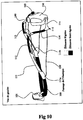
- the strip has stiffer elements for fixing and the passage of a clamping elastic to constrain the deformation of the rigid / semi-rigid strip along the three planes, as shown in the diagram of the figure 2 schematizing a rear perspective of a user whose head receives the headband of the figure 1 .
- the function of the tightening elastic whose length varies, with the function of the strip which remains constant length has been separated.
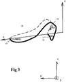
- the figure 3 illustrates a second embodiment of a rigid / semi-rigid headband 20 of a headlamp having a "back" which descends before crossing the median sagittal plane.
- the strip comprises a front portion 11 which is rigid / semi-rigid, allowing the attachment of a lamp via a pivot connection, and which is located approximately in a horizontal plane (x, y) corresponding to a transverse plane of bearer of the lamp.
- the radius of curvature R 1 of the curve 11 which lies in the plane (x, y) is represented.
- the strip 20 follows a curve 13 which is approximately in a plane (y, z) corresponding to the front plane with respect to the user of the lamp and we see the approximation of a radius of "Curvature" equal to R3 ...
- the median sagittal plane serves as a plane of symmetry and the dashed portion corresponds to the part of the strip located "behind" the median sagittal plane.
- the strip 20 comprises an alternation of rigid / semi-rigid elements as will now be described more specifically below, with the Figures 4-22 .
- the front portion 21, the lateral portions 24 and 22, and the rear portion 23 which are all semi-rigid, allow the deformation of the constant length band in the three planes (x, y), (x, z) and (y, z). Provoking the variability of the radii of curvature R1, R2 and R3 for fixing the strip 10 on a head of any size.
- the figure 5 illustrates the positioning of the strip according to the third embodiment on the head of a user.
- the figure 6 illustrates a rear perspective of an embodiment of a rigid / semi-rigid strip according to the third embodiment, where we see that the rear part of the strip - which "rises" - allows the attachment of a battery 38 and a fixing device 39 of the clamping elastic.
- the battery is housed in a rotating rear housing by means of a pivot connection (not shown).
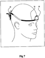
- the figure 7 illustrates a perspective before the banner of the figure 6 where we see distinctively the lamp 40 and the battery in the rear position.
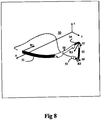
- the figure 8 illustrates a fourth embodiment of a strip 50 also comprising, as for the strip of the figure 4 , an alternation of deformable semi-rigid elements 51, 54, 52, 53 (in dark), and of rigid elements 56, 57, 58 (in clear), allowing the deformation of the constant length band in the three planes ( x, y), (x, z) and (y, z) and the variability of curvature angles R1, R2 and R3, respectively.
- the figure 8 shows a left branch of the headband having a semi-rigid front 51 and three semi-rigid lateral parts 54, 52 and 53.
- the right branch is not represented on the figure 8 for the sake of simplicity, but can be constructed by symmetry with respect to the plane (xz).
- the figure 9 shows the positioning of the fourth embodiment on the head of a user.
- the strip 50 comprises rigid elements (in clear) allowing the attachment and the passage of an elastic, respectively 151 and 150, to ensure the clamping force to constrain the deformation of the rigid / semi-rigid strip along the three planes, reducing the radii of curvature R1-R3.
- the figures 10 and 11 illustrate the detail of a concrete embodiment of a rigid / semi-rigid strip according to the fourth embodiment.
- the headband has an alternation of rigid elements, represented in clear on the figures 7 and 8 , and more flexible elements that are represented in dark.
- the elements may be made of thermoplastic polyurethane (TPU) or polyamide, polyester, PVC with grades chosen to allow the realization of a rigid / semi-rigid structure providing a stable structure (allowing even the positioning the headband on a table as shown in the figure 22 ) while being sufficiently deformable by means of an elastic 150.
- TPU thermoplastic polyurethane
- PVC polyamide, polyester, PVC with grades chosen to allow the realization of a rigid / semi-rigid structure providing a stable structure (allowing even the positioning the headband on a table as shown in the figure 22 ) while being sufficiently deformable by means of an elastic 150.
- the more rigid elements will present a grade included in the range, [73SHD] while the more flexible elements (semi-rigid) will present a grade included in the range of values [ , 70 Sh A].
- the headband which comprises a semi-rigid front portion 100 on which will be fixed a rigid piece called "platinum" serving as support, via a pivot connection, to a lamp 101 comprising one or more LED (s) associated with its electronic circuit.
- the front part can be extruded.
- the lamp 101 comprises a plurality of LEDs of average power, and their associated optics.
- the lamp will take a relatively flat shape, with a large heat dissipation surface, which will make it possible to have directly the LEDs on a circuit board acting as radiator. This will result in a lamp 101 particularly compact.
- the strip further comprises a rear portion 116 rigid (clear) forming a rear portion of the strip.
- the element 116 may become semi-rigid to fit on the xy plane.
- the strip 20 comprises, on its left-hand branch, a first rigid element 111 (of greater rigidity than the semi-rigid element 100) having a first lower end fixed to a first end of the front part 100, as well as a second upper end attached to a second element 112 semi-rigid (dark, so more flexible).
- the rigid element 111 has, respectively at its two lower and upper ends, two passage elements 111a and 111b for a first clamping elastic 150.
- the second semi-rigid element 112 has a first end attached to the second end of the first element 111 and a second end attached to a first end of a third rigid element 113 serving as a point of passage of the elastic 150 coming from the elements 111b of the left branch.
- the strip then comprises a fourth flexible element (semi-rigid) 114 having a first upper end attached to a second end of the third member 113 and a second end attached to a fifth rigid member 115 for fixing the first elastic member 150 from crossing point 111a.
- the left branch of the strip is finally fixed to a first end of the rigid or semi-rigid element 116 forming the rear part of the rigid / semi-rigid strip, via a second end of the rigid element 115.
- the rear portion 116 may be rigid or semi-rigid so that the elements 115 and 116 may be of manufacture or not. When the rear portion 116 will be semi-rigid (dark), then the fifth rigid element 115 will be distinct from the latter. On the contrary, if the rear portion 116 is rigid, the elements 115 and 116 may be identical.
- the figure 10 illustrates the detail of the left branch of the band which is, as we see, perfectly symmetrical with respect to the right branch.
- the right branch comprises a sixth rigid element 121 having a first lower end attached to a second end of the front portion 100 and a second upper end attached to a first end of a seventh flexible element (semi-rigid) 122.
- the rigid element 121 has, respectively at its two lower and upper ends, two passage elements 121a and 121b for a second clamping elastic 151.
- the flexible element 122 has a first end attached to the element 121 and a second end attached to an eighth rigid element 123 serving as a point of passage of the elastic 151 from the element 121b of the left arm.
- the strip then comprises a ninth flexible (semi-rigid) element 124 having a first upper end attached to a second end of the element 123 and a second lower end located at a first end of a tenth rigid element 125 and allowing attachment of the second elastic 151 from the passage point 121a.
- a ninth flexible (semi-rigid) element 124 having a first upper end attached to a second end of the element 123 and a second lower end located at a first end of a tenth rigid element 125 and allowing attachment of the second elastic 151 from the passage point 121a.
- the right branch of the strip is finally attached to the rear (semi-rigid) element 116 which forms the rear of the rigid / semi-rigid strip via a second end of the rigid element 125.
- the figure 12a illustrates the detail of the rigid element 121 comprising, at its two ends 121a and 121b, the passage points of the elastic 151 allowing the stress on the radius of curvature R2 and, consequently, the deformation of the strip in the sagittal plane (x, z)
- the figure 12b illustrates an example of a lamp 101 fixed on the semi-rigid front portion of the strip, and this by means of a pivot having a large amplitude - greater than 180 degrees - on a rigid element at the front of the headband. This pivot function of large amplitude allows, as discussed below, a possibility of additional adjustment of the headlamp when it is used in "neck".
- the pivot of the headlamp is advantageously configured to allow a rotation of about 90 °, which allows a better adaptability to the morphology of the wearer and thus improves comfort.
- This rotation also makes it possible to considerably increase the balance of the lamp when it is placed on a table for example.
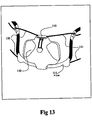
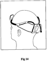
- the strip illustrated in the figures 13 and 14 comprises, at the rear, a battery 130 for supplying power to the lamp 101.
- the battery comprises, on the top, a through hole for the elastics 150 and 151 with a locking button 140 .
- the figure 13 illustrates a rear view of the strip clearly showing the battery 130, the passage hole of the elastics 150 and 151 and the locking button 140.
- the rear portion 116 is made of rigid material such as the element 116, so that the two elements 115 and 116 are made from the same manufacturing process. But this is only a particular embodiment because, once again, the element 116 may be, optionally, semi-rigid material.
- the band forms an overall structure, consisting of an alternation of rigid and semi-rigid elements, which is relatively stable since it can be placed on a table in the manner of any object.
- the headlamp can be used as a table lamp.
- the flexibility of the flexible elements allows deformability of the strip in the space which is achieved by the tightening of the elastics 150 and 151 and their blocking at the locking button 140 located on the top of the battery which, also, can rotate backwards as needed.
- a headband presenting a new aesthetic, a new and original look, which is likely to meet new categories of consumers, potentially put off by the "tool" aspect of traditional headlamps.
- the left and / or right branches of the strip are hollow and their constant length makes it possible to integrate a plurality of electrical conductors and / or optical fibers therein, thus eliminating, in a particularly elegant manner and functional, electrical son that is known in conventional headlamps with an elastic band non-constant length.
- the space will be sufficient to integrate, within the rigid / flexible elements, power conductors and control conductors which will be particularly well protected there.
- the strip comprises a rear light for signaling the lamp holder.
- This rear light can be achieved by means of a secondary lamp attached to the battery 130 or, alternatively, by deporting a fraction of the light created by the lamp 101 through one or more optical fibers. It can thus advantageously deport light from the front to the back.
- a light source in the rear housing (red) with a set of optical fibers to move forward or to the side a fraction of the light (red) generated by the rear housing.
- the front portion 100 or rigid branches 111 and 121 are equipped with switches for controlling the functionality of the lamp, which certainly did not offer the conventional strips.
- one or more displays can be provided to achieve a man-machine ergonomics (HMI) advantageous.
- the left and right branches of the strip are designed to be illuminated so as to allow effective lateral signaling of the lamp holder.
- the figure 14 is a rear perspective, illustrating the positioning of the rigid / semi-rigid strip according to the second embodiment on a small head.
- the figure 15 shows the positioning of the same banner as the one used in the figure 14 , with the same tightening of the elastic, on a head of larger size. It can be seen that the adjustment of the strip made for the figure 14 absolutely does not allow positioning on a larger head. Nevertheless, it suffices to press the button 140 to release the elastics 150-151 and release the deformation of the headband so as to allow it to come to marry the larger head shape of the user considered.
- the figure 17 illustrates the adjustment of the rigid / semi-rigid strip according to the second embodiment on a helmet.
- the new headband has an exceptional ability of adjustment since it allows variations of 19cm of perimeters for the different heads of users, and even the headphones of the figure 17 . This is clearly a significant advantage of this new type of headband.
- the result is particularly convenient new uses, such as around the neck or when hung on a support, such as a tree branch.
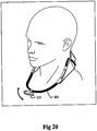
- FIG 20 which illustrates a headlamp has a lamp 210 having a light source which is fixed on a strip for holding the lamp frontal on the head of a user.
- the headband has a rigid / semi-rigid front portion 200 serving as a support for the lamp 210.
- Two pivots, respectively 201 and 202, are arranged on the front portion of the headband to allow a wide pivoting of at least 180 degrees.
- a headlamp is not conventionally provided with the pivot with such an amplitude.
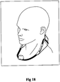
- the figure 18 illustrates a right view of a dummy wearing, around its neck, an embodiment of a headlamp according to the present invention, wherein the lamp is shown in two distinct pivot positions.
- the figure 19a illustrates a left view of a dummy wearing, around its neck, an embodiment of a headlamp according to the present invention.
- the figure 21 is an embodiment of a headband comprising a battery having a fixing means for fixing the lamp on this battery. This results in a possibility of "folding" the lamp in a particularly compact form.
- the figure 22 illustrates a configuration of the headlamp can be positioned on any support, for example a table.
- the figures are given by way of illustration, in no way limiting and, clearly, a person skilled in the art to adopt the new rigid / semi-rigid strip for producing a wide range of lamps.
Landscapes
- Engineering & Computer Science (AREA)
- General Engineering & Computer Science (AREA)
- Physics & Mathematics (AREA)
- General Physics & Mathematics (AREA)
- Optics & Photonics (AREA)
- Helmets And Other Head Coverings (AREA)
- Non-Portable Lighting Devices Or Systems Thereof (AREA)
- Arrangement Of Elements, Cooling, Sealing, Or The Like Of Lighting Devices (AREA)
Claims (12)
- Stirnlampe, umfassend:- eine Lampe (40) mit einer Lichtquelle;- ein Band (50) zum Befestigen der Lampe am Kopf eines Benutzers,
wobei das Band eine konstante Länge aufweist, symmetrisch in Bezug auf eine mittlere Sagittalebene, und dadurch gekennzeichnet, dass es einen Wechsel von starren/halbstarren Elementen (56, 57, 58; 51-54) umfasst, um eine Verformung im Raum und eine Anpassung an den Kopf eines Benutzers zu ermöglichen. - Stirnlampe nach Anspruch 1, dadurch gekennzeichnet, dass das Stirnband (50) Folgendes umfasst- einen starren/halbstarren Vorderteil (100), der eine Verformbarkeit entlang einer ersten Ebene (x, y) ermöglicht;- einen starren/halbstarren Zwischenabschnitt (111-115, 121-125), der eine Verformbarkeit entlang einer zweiten Ebene (x, z) ermöglicht;- einen starren/halbstarren Hinterteil (116), der eine Verformbarkeit entlang einer dritten Ebene (y, z) ermöglicht,
wobei das Band Elemente (111a, 111b, 121a, 121b) beinhaltet, die die Befestigung und den Durchgang eines elastischen Klemmbandes (150, 151) ermöglichen, das es ermöglicht, die Verformung des starren/halbstarren Bandes gemäß den drei Ebenen zu begrenzen. - Stirnlampe nach Anspruch 2, dadurch gekennzeichnet, dass sie an der Rückseite eine Batterie (130) für die elektrische Stromversorgung der Lampe umfasst.
- Stirnlampe nach Anspruch 3, dadurch gekennzeichnet, dass sie ein System zum Befestigen der Batterie an der Lampe umfasst, um das Falten und die kompakte Lagerung des Stirnlampes zu ermöglichen.
- Stirnlampe nach Anspruch 2, dadurch gekennzeichnet, dass sie an der Rückseite ein Rücklicht umfasst.
- Stirnlampe nach Anspruch 2, dadurch gekennzeichnet, dass das Stirnband hohl ist und eine Vielzahl von elektrischen Leitern aufweist, die der elektrischen Versorgung der Lampe und/oder der Steuerung der Funktionen der Lampe dienen.
- Stirnlampe nach Anspruch 2, dadurch gekennzeichnet, dass das Band eine oder mehrere Lichtleitfasern beinhaltet, um einen Teil des von der Lampe erzeugten Lichtstrahls nach hinten zu transportieren oder alternativ um einen Teil des Lichts nach vorne oder an den Seiten einen von einem hinteren Gehäuse erzeugten Lichtstrahl zu transportieren.
- Stirnlampe nach Anspruch 6, dadurch gekennzeichnet, dass das Stirnband mit Schaltern und/oder einer Anzeige zum Steuern der Funktionen der Lampe versehen ist.
- Stirnlampe nach Anspruch 1, dadurch gekennzeichnet, dass sie umfasst:- einen Vorderteil (100), der aus einem ersten halbstarren Element besteht;
einen hinteren Teil (116), bestehend aus einem starren oder halbstarren Element- einen linken Ast, bestehend aus:- einem ersten starren Element (111) mit einem ersten unteren Ende und einem zweiten oberen Ende,
wobei das erste starre Element (111) eine größere Steifigkeit aufweist als die vorderen (100) oder hinteren (116) Teile,
wobei das erste Ende des ersten starren Elements (111) an einem ersten Ende des Vorderteils (100) befestigt ist, wobei das erste starre Element (111) an seinen beiden unteren und oberen Enden jeweils ein erstes und ein zweites Durchgangselement (111a, 111b) für ein erstes klemmendes Elastik (150) aufweist;- ein zweites halbstarres Element (112) mit einem ersten Ende und einem zweiten Ende,
wobei das erste Ende des zweiten Elements (112) an dem zweiten Ende des ersten Elements (111) befestigt ist;- ein drittes starres Element (113) mit einem ersten Ende und einem zweiten Ende und mit einem Durchgangsloch für das erste elastische (150) vom zweiten Durchlasselement (111b) des ersten Elements (111);
wobei das erste Ende des dritten Elements (113) an dem zweiten Ende des zweiten Elements (112) befestigt ist;- ein viertes halbstarres Element (114) mit einem ersten Ende und einem zweiten Ende;
wobei das erste Ende des vierten Elements (114) an dem zweiten Ende des dritten Elements (113) befestigt ist;- ein fünftes starres Element (115) mit einem ersten Ende und einem zweiten Ende;einen rechten Zweig, bestehend aus:
wobei das erste Ende des fünften Elements (115) an dem zweiten Ende des vierten Elements (114) befestigt ist;
wobei das zweite Ende des fünften Elements (115) an einem ersten Ende des hinteren Teils (116) befestigt ist;
wobei das fünfte Element (115) die Befestigung des elastischen (150) vom ersten Durchgangselement (111a) des ersten Elements (111) ermöglicht;- ein sechstes starres Element (121) mit einem ersten unteren Ende und einem zweiten oberen Ende, wobei das sechste starre Element (121) eine höhere Steifigkeit aufweist als die vorderen (100) oder hinteren Teile (116)),
wobei das erste Ende des sechsten Elements (121) an einem zweiten Ende des Vorderteils (100) befestigt ist, wobei das sechste Element (121) sowohl an seinem unteren als auch an seinem oberen Ende jeweils ein erstes und ein zweites Durchgangselement (121a, 121b) für ein zweites klemmendes elastisches (151) aufweist;- ein siebtes halbstarres Element (122) mit einem ersten Ende und einem zweiten Ende,
wobei das erste Ende des siebten Elements (122) an dem zweiten Ende des sechsten Elements (121) befestigt ist;- ein achtes starres Element (123) mit einem ersten Ende und einem zweiten Ende und mit einem Durchgangsloch für das zweite elastische (151) vom zweiten Durchgangselement (121b) des sechsten Elements (121);
wobei das erste Ende des achten Elements (123) an dem zweiten Ende des siebten Elements (122) befestigt ist;- ein neuntes halbstarres Element (124) mit einem ersten Ende und einem zweiten Ende;
wobei das erste Ende des neunten Elements (124) an dem zweiten Ende des achten Elements (123) befestigt ist;- ein zehntes starres Element (125) mit einem ersten Ende und einem zweiten Ende;
wobei das erste Ende des zehnten Elements (125) an dem zweiten Ende des neunten Elements (124) befestigt ist;
wobei das zweite Ende des zehnten Elements (125) an einem zweiten Ende des hinteren Teils (116) befestigt ist; wobei das zehnte Element (125) die Befestigung des zweiten elastischen Elements (151) vom ersten Durchgangselement (121a) des sechsten Elements (121) ermöglicht. - Stirnlampe nach einem der Ansprüche 2 bis 9, wobei die Stirnlampe (20) mit mindestens einem Drehpunkt versehen ist, um ein Schwenken an dem vorderen Teil des Stirnbandes zu ermöglichen, und konfiguriert ist, um eine Drehung von mindestens 180 Grad zu ermöglichen.
- Stirnlampe nach Anspruch 10, dadurch gekennzeichnet, dass die Drehung es ermöglicht, den Lichtstrahl der Lampe für die horizontale Beleuchtung, aber auch nach unten, wenn die Lampe um den Hals getragen wird, einzustellen.
- Stirnlampe nach einem der vorstehenden Ansprüche, dadurch gekennzeichnet, dass sie ein in Drehung verstellbares Hintergehäuse umfasst, um verschiedene hintere Signalanordnungen zu ermöglichen.
Priority Applications (1)
| Application Number | Priority Date | Filing Date | Title |
|---|---|---|---|
| PL17188218T PL3290785T3 (pl) | 2016-08-29 | 2017-08-28 | Latarka czołowa ze sztywną lub półsztywną opaską |
Applications Claiming Priority (1)
| Application Number | Priority Date | Filing Date | Title |
|---|---|---|---|
| FR1601270A FR3055394B1 (fr) | 2016-08-29 | 2016-08-29 | Lampe frontale dote d'un bandeau rigide ou semi/rigide |
Publications (2)
| Publication Number | Publication Date |
|---|---|
| EP3290785A1 EP3290785A1 (de) | 2018-03-07 |
| EP3290785B1 true EP3290785B1 (de) | 2019-05-15 |
Family
ID=57960474
Family Applications (1)
| Application Number | Title | Priority Date | Filing Date |
|---|---|---|---|
| EP17188218.6A Active EP3290785B1 (de) | 2016-08-29 | 2017-08-28 | Stirnlampe, die mit einem starren oder halbstarren band versehen ist |
Country Status (6)
| Country | Link |
|---|---|
| US (1) | US10544926B2 (de) |
| EP (1) | EP3290785B1 (de) |
| CN (1) | CN107795870B (de) |
| FR (1) | FR3055394B1 (de) |
| PL (1) | PL3290785T3 (de) |
| TW (1) | TWI764915B (de) |
Families Citing this family (4)
| Publication number | Priority date | Publication date | Assignee | Title |
|---|---|---|---|---|
| US11473761B2 (en) * | 2018-06-21 | 2022-10-18 | Biolite Inc. | Headlamp integrated into a flexible composite headband |
| FR3091328A1 (fr) | 2018-12-31 | 2020-07-03 | Zedel | Dispositif d’équilibrage améliorant le maintien sur la tête d’une lampe frontale |
| US10859245B2 (en) | 2019-02-01 | 2020-12-08 | Milwaukee Electric Tool Corporation | High visibility headlamp |
| EP4047261B1 (de) * | 2021-02-23 | 2025-05-21 | Zedel | Stirnband für stirnlampe |
Family Cites Families (8)
| Publication number | Priority date | Publication date | Assignee | Title |
|---|---|---|---|---|
| US20070177376A1 (en) * | 2003-12-31 | 2007-08-02 | Simoni Jacquelyn R | Hands-free flashlight |
| AU2008207968B2 (en) * | 2007-01-23 | 2013-08-29 | Energizer Brands, Llc | Headlamp with adjustable diffuser lens |
| US20080298048A1 (en) * | 2007-06-01 | 2008-12-04 | Garrity Industries, Inc. | Headlamp with detachable led flashlight |
| FR2971037A1 (fr) * | 2011-02-01 | 2012-08-03 | Zedel | Lampe d'eclairage electrique portative, a fixation perfectionnee |
| CN103216793A (zh) * | 2013-05-07 | 2013-07-24 | 宁波山力士户外用品有限公司 | 一种头灯的头部大小调节装置 |
| TWM484668U (zh) * | 2014-04-17 | 2014-08-21 | Huo-Quan Chen | 固定用頭燈裝置 |
| FR3049332A1 (fr) * | 2016-03-22 | 2017-09-29 | Zedel | Lampe frontale dotee d'une signalisation arriere |
| FR3055393B1 (fr) * | 2016-08-29 | 2018-09-21 | Zedel | Lampe frontale adaptee pour un tour de cou |
-
2016
- 2016-08-29 FR FR1601270A patent/FR3055394B1/fr active Active
-
2017
- 2017-08-11 TW TW106127252A patent/TWI764915B/zh not_active IP Right Cessation
- 2017-08-28 EP EP17188218.6A patent/EP3290785B1/de active Active
- 2017-08-28 US US15/688,463 patent/US10544926B2/en active Active
- 2017-08-28 PL PL17188218T patent/PL3290785T3/pl unknown
- 2017-08-29 CN CN201710756958.7A patent/CN107795870B/zh not_active Expired - Fee Related
Non-Patent Citations (1)
| Title |
|---|
| None * |
Also Published As
| Publication number | Publication date |
|---|---|
| US20180058669A1 (en) | 2018-03-01 |
| TWI764915B (zh) | 2022-05-21 |
| PL3290785T3 (pl) | 2019-12-31 |
| FR3055394B1 (fr) | 2018-09-21 |
| US10544926B2 (en) | 2020-01-28 |
| CN107795870A (zh) | 2018-03-13 |
| FR3055394A1 (fr) | 2018-03-02 |
| CN107795870B (zh) | 2022-03-18 |
| TW201807347A (zh) | 2018-03-01 |
| EP3290785A1 (de) | 2018-03-07 |
Similar Documents
| Publication | Publication Date | Title |
|---|---|---|
| CA2735648C (en) | Illuminated eyewear | |
| EP3293451B1 (de) | Stirnlampe für trageband | |
| EP3674596B1 (de) | Ausgleichsvorrichtung zur verbesserung des haltens auf dem kopf einer stirnlampe | |
| ES2547907T3 (es) | Gafas iluminadas | |
| US8491118B2 (en) | Lighted reading glasses | |
| US20120155064A1 (en) | Rechargeable lighted glasses | |
| FR2798720A1 (fr) | Dispositif d'eclairage destine a equiper un support, notamment textile | |
| EP3290785A1 (de) | Stirnlampe, die mit einem starren oder halbstarren band versehen ist | |
| FR2691051A1 (fr) | Dispositif de fixation d'une paire de lunettes à un couvre-chef. | |
| FR2971037A1 (fr) | Lampe d'eclairage electrique portative, a fixation perfectionnee | |
| FR2798721A1 (fr) | Dispositif d'eclairage mains libres integre a un couvre-chef | |
| FR3037154A1 (fr) | Monture de lunettes comportant au moins un organe fonctionnel | |
| FR2965706A1 (fr) | Support de lunettes | |
| EP2590001B1 (de) | Lupe mit Beleuchtung | |
| FR2987980A1 (fr) | Casque de protection comprenant un dispositif d'eclairage | |
| FR2532070A1 (fr) | Lunettes-retroviseurs | |
| CA2540872A1 (fr) | Lunettes a lentilles clippees | |
| FR2828553A1 (fr) | Perfectionnement pour lampe frontale ameliorant le confort pour l'utilisateur | |
| FR3054681B1 (fr) | Dispositif formant lunettes a verres deplacables, notamment pour maquillage | |
| FR2828552A1 (fr) | Perfectionnement pour lampe frontale | |
| WO2019097174A1 (fr) | Systeme d'eclairage d'un poste de travail | |
| EP1540408A1 (de) | Neuartiges verfahren zum zusammenbauen von sichtbrillen und so erhaltene produkte | |
| EP1677049A2 (de) | Lampe, die an einer Person anbringbar ist | |
| FR2730826A1 (fr) | Monture de lunettes solaires a protection laterale | |
| FR2995094A1 (fr) | Monture de lunettes pour branches interchangeables |
Legal Events
| Date | Code | Title | Description |
|---|---|---|---|
| PUAI | Public reference made under article 153(3) epc to a published international application that has entered the european phase |
Free format text: ORIGINAL CODE: 0009012 |
|
| STAA | Information on the status of an ep patent application or granted ep patent |
Free format text: STATUS: THE APPLICATION HAS BEEN PUBLISHED |
|
| AK | Designated contracting states |
Kind code of ref document: A1 Designated state(s): AL AT BE BG CH CY CZ DE DK EE ES FI FR GB GR HR HU IE IS IT LI LT LU LV MC MK MT NL NO PL PT RO RS SE SI SK SM TR |
|
| AX | Request for extension of the european patent |
Extension state: BA ME |
|
| STAA | Information on the status of an ep patent application or granted ep patent |
Free format text: STATUS: REQUEST FOR EXAMINATION WAS MADE |
|
| 17P | Request for examination filed |
Effective date: 20180907 |
|
| RBV | Designated contracting states (corrected) |
Designated state(s): AL AT BE BG CH CY CZ DE DK EE ES FI FR GB GR HR HU IE IS IT LI LT LU LV MC MK MT NL NO PL PT RO RS SE SI SK SM TR |
|
| GRAP | Despatch of communication of intention to grant a patent |
Free format text: ORIGINAL CODE: EPIDOSNIGR1 |
|
| STAA | Information on the status of an ep patent application or granted ep patent |
Free format text: STATUS: GRANT OF PATENT IS INTENDED |
|
| RIC1 | Information provided on ipc code assigned before grant |
Ipc: F21V 21/14 20060101ALN20181024BHEP Ipc: F21Y 115/10 20160101ALN20181024BHEP Ipc: F21Y 101/00 20160101ALN20181024BHEP Ipc: F21V 21/084 20060101AFI20181024BHEP |
|
| INTG | Intention to grant announced |
Effective date: 20181205 |
|
| GRAS | Grant fee paid |
Free format text: ORIGINAL CODE: EPIDOSNIGR3 |
|
| GRAA | (expected) grant |
Free format text: ORIGINAL CODE: 0009210 |
|
| STAA | Information on the status of an ep patent application or granted ep patent |
Free format text: STATUS: THE PATENT HAS BEEN GRANTED |
|
| AK | Designated contracting states |
Kind code of ref document: B1 Designated state(s): AL AT BE BG CH CY CZ DE DK EE ES FI FR GB GR HR HU IE IS IT LI LT LU LV MC MK MT NL NO PL PT RO RS SE SI SK SM TR |
|
| REG | Reference to a national code |
Ref country code: CH Ref legal event code: EP |
|
| REG | Reference to a national code |
Ref country code: DE Ref legal event code: R096 Ref document number: 602017003900 Country of ref document: DE |
|
| REG | Reference to a national code |
Ref country code: IE Ref legal event code: FG4D Free format text: LANGUAGE OF EP DOCUMENT: FRENCH |
|
| REG | Reference to a national code |
Ref country code: CH Ref legal event code: NV Representative=s name: RENTSCH PARTNER AG, CH |
|
| REG | Reference to a national code |
Ref country code: SE Ref legal event code: TRGR |
|
| REG | Reference to a national code |
Ref country code: NL Ref legal event code: MP Effective date: 20190515 |
|
| REG | Reference to a national code |
Ref country code: LT Ref legal event code: MG4D |
|
| REG | Reference to a national code |
Ref country code: NO Ref legal event code: T2 Effective date: 20190515 |
|
| PG25 | Lapsed in a contracting state [announced via postgrant information from national office to epo] |
Ref country code: LT Free format text: LAPSE BECAUSE OF FAILURE TO SUBMIT A TRANSLATION OF THE DESCRIPTION OR TO PAY THE FEE WITHIN THE PRESCRIBED TIME-LIMIT Effective date: 20190515 Ref country code: NL Free format text: LAPSE BECAUSE OF FAILURE TO SUBMIT A TRANSLATION OF THE DESCRIPTION OR TO PAY THE FEE WITHIN THE PRESCRIBED TIME-LIMIT Effective date: 20190515 Ref country code: PT Free format text: LAPSE BECAUSE OF FAILURE TO SUBMIT A TRANSLATION OF THE DESCRIPTION OR TO PAY THE FEE WITHIN THE PRESCRIBED TIME-LIMIT Effective date: 20190915 Ref country code: AL Free format text: LAPSE BECAUSE OF FAILURE TO SUBMIT A TRANSLATION OF THE DESCRIPTION OR TO PAY THE FEE WITHIN THE PRESCRIBED TIME-LIMIT Effective date: 20190515 Ref country code: ES Free format text: LAPSE BECAUSE OF FAILURE TO SUBMIT A TRANSLATION OF THE DESCRIPTION OR TO PAY THE FEE WITHIN THE PRESCRIBED TIME-LIMIT Effective date: 20190515 Ref country code: HR Free format text: LAPSE BECAUSE OF FAILURE TO SUBMIT A TRANSLATION OF THE DESCRIPTION OR TO PAY THE FEE WITHIN THE PRESCRIBED TIME-LIMIT Effective date: 20190515 |
|
| PG25 | Lapsed in a contracting state [announced via postgrant information from national office to epo] |
Ref country code: BG Free format text: LAPSE BECAUSE OF FAILURE TO SUBMIT A TRANSLATION OF THE DESCRIPTION OR TO PAY THE FEE WITHIN THE PRESCRIBED TIME-LIMIT Effective date: 20190815 Ref country code: LV Free format text: LAPSE BECAUSE OF FAILURE TO SUBMIT A TRANSLATION OF THE DESCRIPTION OR TO PAY THE FEE WITHIN THE PRESCRIBED TIME-LIMIT Effective date: 20190515 Ref country code: RS Free format text: LAPSE BECAUSE OF FAILURE TO SUBMIT A TRANSLATION OF THE DESCRIPTION OR TO PAY THE FEE WITHIN THE PRESCRIBED TIME-LIMIT Effective date: 20190515 Ref country code: GR Free format text: LAPSE BECAUSE OF FAILURE TO SUBMIT A TRANSLATION OF THE DESCRIPTION OR TO PAY THE FEE WITHIN THE PRESCRIBED TIME-LIMIT Effective date: 20190816 |
|
| PG25 | Lapsed in a contracting state [announced via postgrant information from national office to epo] |
Ref country code: DK Free format text: LAPSE BECAUSE OF FAILURE TO SUBMIT A TRANSLATION OF THE DESCRIPTION OR TO PAY THE FEE WITHIN THE PRESCRIBED TIME-LIMIT Effective date: 20190515 Ref country code: EE Free format text: LAPSE BECAUSE OF FAILURE TO SUBMIT A TRANSLATION OF THE DESCRIPTION OR TO PAY THE FEE WITHIN THE PRESCRIBED TIME-LIMIT Effective date: 20190515 Ref country code: SK Free format text: LAPSE BECAUSE OF FAILURE TO SUBMIT A TRANSLATION OF THE DESCRIPTION OR TO PAY THE FEE WITHIN THE PRESCRIBED TIME-LIMIT Effective date: 20190515 |
|
| REG | Reference to a national code |
Ref country code: DE Ref legal event code: R097 Ref document number: 602017003900 Country of ref document: DE |
|
| PG25 | Lapsed in a contracting state [announced via postgrant information from national office to epo] |
Ref country code: SM Free format text: LAPSE BECAUSE OF FAILURE TO SUBMIT A TRANSLATION OF THE DESCRIPTION OR TO PAY THE FEE WITHIN THE PRESCRIBED TIME-LIMIT Effective date: 20190515 |
|
| PLBE | No opposition filed within time limit |
Free format text: ORIGINAL CODE: 0009261 |
|
| STAA | Information on the status of an ep patent application or granted ep patent |
Free format text: STATUS: NO OPPOSITION FILED WITHIN TIME LIMIT |
|
| PG25 | Lapsed in a contracting state [announced via postgrant information from national office to epo] |
Ref country code: TR Free format text: LAPSE BECAUSE OF FAILURE TO SUBMIT A TRANSLATION OF THE DESCRIPTION OR TO PAY THE FEE WITHIN THE PRESCRIBED TIME-LIMIT Effective date: 20190515 |
|
| 26N | No opposition filed |
Effective date: 20200218 |
|
| PG25 | Lapsed in a contracting state [announced via postgrant information from national office to epo] |
Ref country code: SI Free format text: LAPSE BECAUSE OF FAILURE TO SUBMIT A TRANSLATION OF THE DESCRIPTION OR TO PAY THE FEE WITHIN THE PRESCRIBED TIME-LIMIT Effective date: 20190515 Ref country code: LU Free format text: LAPSE BECAUSE OF NON-PAYMENT OF DUE FEES Effective date: 20190828 Ref country code: MC Free format text: LAPSE BECAUSE OF FAILURE TO SUBMIT A TRANSLATION OF THE DESCRIPTION OR TO PAY THE FEE WITHIN THE PRESCRIBED TIME-LIMIT Effective date: 20190515 |
|
| REG | Reference to a national code |
Ref country code: BE Ref legal event code: MM Effective date: 20190831 |
|
| REG | Reference to a national code |
Ref country code: AT Ref legal event code: UEP Ref document number: 1133861 Country of ref document: AT Kind code of ref document: T Effective date: 20190515 |
|
| PG25 | Lapsed in a contracting state [announced via postgrant information from national office to epo] |
Ref country code: IE Free format text: LAPSE BECAUSE OF NON-PAYMENT OF DUE FEES Effective date: 20190828 |
|
| PG25 | Lapsed in a contracting state [announced via postgrant information from national office to epo] |
Ref country code: BE Free format text: LAPSE BECAUSE OF NON-PAYMENT OF DUE FEES Effective date: 20190831 |
|
| PG25 | Lapsed in a contracting state [announced via postgrant information from national office to epo] |
Ref country code: RO Free format text: LAPSE BECAUSE OF FAILURE TO SUBMIT A TRANSLATION OF THE DESCRIPTION OR TO PAY THE FEE WITHIN THE PRESCRIBED TIME-LIMIT Effective date: 20190515 |
|
| PG25 | Lapsed in a contracting state [announced via postgrant information from national office to epo] |
Ref country code: CY Free format text: LAPSE BECAUSE OF FAILURE TO SUBMIT A TRANSLATION OF THE DESCRIPTION OR TO PAY THE FEE WITHIN THE PRESCRIBED TIME-LIMIT Effective date: 20190515 |
|
| PG25 | Lapsed in a contracting state [announced via postgrant information from national office to epo] |
Ref country code: IS Free format text: LAPSE BECAUSE OF FAILURE TO SUBMIT A TRANSLATION OF THE DESCRIPTION OR TO PAY THE FEE WITHIN THE PRESCRIBED TIME-LIMIT Effective date: 20190915 |
|
| PG25 | Lapsed in a contracting state [announced via postgrant information from national office to epo] |
Ref country code: HU Free format text: LAPSE BECAUSE OF FAILURE TO SUBMIT A TRANSLATION OF THE DESCRIPTION OR TO PAY THE FEE WITHIN THE PRESCRIBED TIME-LIMIT; INVALID AB INITIO Effective date: 20170828 Ref country code: MT Free format text: LAPSE BECAUSE OF FAILURE TO SUBMIT A TRANSLATION OF THE DESCRIPTION OR TO PAY THE FEE WITHIN THE PRESCRIBED TIME-LIMIT Effective date: 20190515 |
|
| PG25 | Lapsed in a contracting state [announced via postgrant information from national office to epo] |
Ref country code: MK Free format text: LAPSE BECAUSE OF FAILURE TO SUBMIT A TRANSLATION OF THE DESCRIPTION OR TO PAY THE FEE WITHIN THE PRESCRIBED TIME-LIMIT Effective date: 20190515 |
|
| PGFP | Annual fee paid to national office [announced via postgrant information from national office to epo] |
Ref country code: DE Payment date: 20240819 Year of fee payment: 8 Ref country code: FI Payment date: 20240820 Year of fee payment: 8 |
|
| PGFP | Annual fee paid to national office [announced via postgrant information from national office to epo] |
Ref country code: GB Payment date: 20240822 Year of fee payment: 8 |
|
| PGFP | Annual fee paid to national office [announced via postgrant information from national office to epo] |
Ref country code: CH Payment date: 20240901 Year of fee payment: 8 |
|
| PGFP | Annual fee paid to national office [announced via postgrant information from national office to epo] |
Ref country code: CZ Payment date: 20240815 Year of fee payment: 8 |
|
| PGFP | Annual fee paid to national office [announced via postgrant information from national office to epo] |
Ref country code: AT Payment date: 20240819 Year of fee payment: 8 |
|
| PGFP | Annual fee paid to national office [announced via postgrant information from national office to epo] |
Ref country code: PL Payment date: 20240820 Year of fee payment: 8 |
|
| PGFP | Annual fee paid to national office [announced via postgrant information from national office to epo] |
Ref country code: NO Payment date: 20240820 Year of fee payment: 8 Ref country code: IT Payment date: 20240830 Year of fee payment: 8 Ref country code: SE Payment date: 20240821 Year of fee payment: 8 |
|
| PGFP | Annual fee paid to national office [announced via postgrant information from national office to epo] |
Ref country code: FR Payment date: 20250821 Year of fee payment: 9 |
|
| REG | Reference to a national code |
Ref country code: DE Ref legal event code: R119 Ref document number: 602017003900 Country of ref document: DE |
|
| REG | Reference to a national code |
Ref country code: CH Ref legal event code: H13 Free format text: ST27 STATUS EVENT CODE: U-0-0-H10-H13 (AS PROVIDED BY THE NATIONAL OFFICE) Effective date: 20260324 |
|
| PG25 | Lapsed in a contracting state [announced via postgrant information from national office to epo] |
Ref country code: NO Free format text: LAPSE BECAUSE OF NON-PAYMENT OF DUE FEES Effective date: 20250831 |
|
| PG25 | Lapsed in a contracting state [announced via postgrant information from national office to epo] |
Ref country code: AT Free format text: LAPSE BECAUSE OF NON-PAYMENT OF DUE FEES Effective date: 20250828 Ref country code: FI Free format text: LAPSE BECAUSE OF NON-PAYMENT OF DUE FEES Effective date: 20250828 |
|
| REG | Reference to a national code |
Ref country code: AT Ref legal event code: MM01 Ref document number: 1133861 Country of ref document: AT Kind code of ref document: T Effective date: 20250828 |
|
| PG25 | Lapsed in a contracting state [announced via postgrant information from national office to epo] |
Ref country code: CZ Free format text: LAPSE BECAUSE OF NON-PAYMENT OF DUE FEES Effective date: 20250828 Ref country code: CH Free format text: LAPSE BECAUSE OF NON-PAYMENT OF DUE FEES Effective date: 20250831 |
|
| GBPC | Gb: european patent ceased through non-payment of renewal fee |
Effective date: 20250828 |
|
| PG25 | Lapsed in a contracting state [announced via postgrant information from national office to epo] |
Ref country code: GB Free format text: LAPSE BECAUSE OF NON-PAYMENT OF DUE FEES Effective date: 20250828 |
|
| PG25 | Lapsed in a contracting state [announced via postgrant information from national office to epo] |
Ref country code: IT Free format text: LAPSE BECAUSE OF NON-PAYMENT OF DUE FEES Effective date: 20250828 |
|
| PG25 | Lapsed in a contracting state [announced via postgrant information from national office to epo] |
Ref country code: DE Free format text: LAPSE BECAUSE OF NON-PAYMENT OF DUE FEES Effective date: 20260303 |
|
| PG25 | Lapsed in a contracting state [announced via postgrant information from national office to epo] |
Ref country code: SE Free format text: LAPSE BECAUSE OF NON-PAYMENT OF DUE FEES Effective date: 20250829 |