EP3290790B1 - Kühlkörper - Google Patents
Kühlkörper Download PDFInfo
- Publication number
- EP3290790B1 EP3290790B1 EP16186226.3A EP16186226A EP3290790B1 EP 3290790 B1 EP3290790 B1 EP 3290790B1 EP 16186226 A EP16186226 A EP 16186226A EP 3290790 B1 EP3290790 B1 EP 3290790B1
- Authority
- EP
- European Patent Office
- Prior art keywords
- heatsink
- light source
- luminaire
- driver
- housing
- Prior art date
- Legal status (The legal status is an assumption and is not a legal conclusion. Google has not performed a legal analysis and makes no representation as to the accuracy of the status listed.)
- Not-in-force
Links
Images

Classifications
-
- F—MECHANICAL ENGINEERING; LIGHTING; HEATING; WEAPONS; BLASTING
- F21—LIGHTING
- F21V—FUNCTIONAL FEATURES OR DETAILS OF LIGHTING DEVICES OR SYSTEMS THEREOF; STRUCTURAL COMBINATIONS OF LIGHTING DEVICES WITH OTHER ARTICLES, NOT OTHERWISE PROVIDED FOR
- F21V29/00—Protecting lighting devices from thermal damage; Cooling or heating arrangements specially adapted for lighting devices or systems
- F21V29/50—Cooling arrangements
- F21V29/502—Cooling arrangements characterised by the adaptation for cooling of specific components
- F21V29/508—Cooling arrangements characterised by the adaptation for cooling of specific components of electrical circuits
-
- F—MECHANICAL ENGINEERING; LIGHTING; HEATING; WEAPONS; BLASTING
- F21—LIGHTING
- F21V—FUNCTIONAL FEATURES OR DETAILS OF LIGHTING DEVICES OR SYSTEMS THEREOF; STRUCTURAL COMBINATIONS OF LIGHTING DEVICES WITH OTHER ARTICLES, NOT OTHERWISE PROVIDED FOR
- F21V29/00—Protecting lighting devices from thermal damage; Cooling or heating arrangements specially adapted for lighting devices or systems
- F21V29/50—Cooling arrangements
- F21V29/70—Cooling arrangements characterised by passive heat-dissipating elements, e.g. heat-sinks
- F21V29/74—Cooling arrangements characterised by passive heat-dissipating elements, e.g. heat-sinks with fins or blades
- F21V29/77—Cooling arrangements characterised by passive heat-dissipating elements, e.g. heat-sinks with fins or blades with essentially identical diverging planar fins or blades, e.g. with fan-like or star-like cross-section
- F21V29/773—Cooling arrangements characterised by passive heat-dissipating elements, e.g. heat-sinks with fins or blades with essentially identical diverging planar fins or blades, e.g. with fan-like or star-like cross-section the planes containing the fins or blades having the direction of the light emitting axis
-
- F—MECHANICAL ENGINEERING; LIGHTING; HEATING; WEAPONS; BLASTING
- F21—LIGHTING
- F21Y—INDEXING SCHEME ASSOCIATED WITH SUBCLASSES F21K, F21L, F21S and F21V, RELATING TO THE FORM OR THE KIND OF THE LIGHT SOURCES OR OF THE COLOUR OF THE LIGHT EMITTED
- F21Y2105/00—Planar light sources
- F21Y2105/10—Planar light sources comprising a two-dimensional [2D] array of point-like light-generating elements
- F21Y2105/14—Planar light sources comprising a two-dimensional [2D] array of point-like light-generating elements characterised by the overall shape of the two-dimensional [2D] array
- F21Y2105/18—Planar light sources comprising a two-dimensional [2D] array of point-like light-generating elements characterised by the overall shape of the two-dimensional [2D] array annular; polygonal other than square or rectangular, e.g. for spotlights or for generating an axially symmetrical light beam
-
- F—MECHANICAL ENGINEERING; LIGHTING; HEATING; WEAPONS; BLASTING
- F21—LIGHTING
- F21Y—INDEXING SCHEME ASSOCIATED WITH SUBCLASSES F21K, F21L, F21S and F21V, RELATING TO THE FORM OR THE KIND OF THE LIGHT SOURCES OR OF THE COLOUR OF THE LIGHT EMITTED
- F21Y2115/00—Light-generating elements of semiconductor light sources
- F21Y2115/10—Light-emitting diodes [LED]
Definitions
- the present invention relates to luminaires having a high lumen output resulting in an excessive heat generation.
- the present invention relates to a heatsink which is used in such a luminaire.
- luminaires having a high lumen output are well known.
- Those luminaires usually comprise a driver and a light source having a light emitting direction of the light source for constituting a main beam direction of the luminaire.
- the driver is usually provided somewhere at the rear side a housing of a central supporting element of the luminaire with respect to the light emitting direction of the light source.
- WO 2015/186016 A1 is directed to heat sinks for light emitting devices.
- the heat sinks can provide effective heat dissipation in a variety of different orientations and positions.
- different groups of essentially parallel fins can be separated and disposed at particular angles to form fluid channels that enable fluid flow in different directions and orientations.
- WO 2013/057433 A1 relates to an illuminating device comprising light-emitting diodes, said device being equipped with a heat dissipator comprising inter alia a radiator.
- the radiator consisting of a single-part element, comprises a plate and fins extending around said plate, said fins being oriented substantially perpendicular to said plate in such a way as to allow the light-emitting diodes to be cooled by natural convection.
- an LED-based luminaire employs an LED module mounted to a housing.
- the LED module is advantageously configured to transmit heat generated by the LEDs across and/or through the module and to the housing for dispersal to the environment.
- LED modules can be configured with conductive or non-conductive cores and may be configured to evacuate heat from one or both faces of the LED module. Multiple heat paths can be defined from components on an LED module to the housing and to the environment.
- heatsinks are known being in thermal contact with heat generating components of the luminaire and having an enlarged surface configuration for transferring the heat to the surrounding air. These heatsinks have been optimized in the past and indeed help to keep the temperatures in luminaires at an acceptable level. On the other hand, in case such heatsinks are in thermal contact with the light source and other electric components such as drivers, there is a risk that the heatsink even supports a transfer of heat from the light source to the driver or in the other direction.
- a heatsink for a luminaire comprising a first portion being adapted for arranging a light source driver, an emergency lighting unit or a housing for accommodating a light source driver or an emergency lighting unit; and a second portion being integrally formed with the first portion and adapted for arranging a light source.
- the heatsink further comprises support elements extending from the first portion of the heatsink to the second portion.
- the invention is characterized in that the support elements comprise a cut which splits each support element in two portions and wherein the cut diagonally extends through the support element, preventing a transfer of heat from the light source to the electrical components or in the other direction.
- an integrally formed heatsink which is used to cool simultaneously the light source and other electrical components wherein nevertheless a (cross) transfer of heat is prevented by using cooling fins having a gap.
- Each gap divides the corresponding cooling fin then in a first cooling fin portion and a second cooling fin portion wherein both portions are aligned with each other.
- the gap preferably separates both cooling fin portions by distance of around 3 to 7 mm, preferably by around 5mm.
- the length ratio between the cooling fin portions can be adapted.
- the length ration between the first cooling fin portion and the second cooling fin portion is around 1:4 considering the fact that usually the light source generates more heat than the light source driver.
- the heatsink has a circular configuration with the first portion forming a center portion of the heatsink and the second portion forming an outer portion.
- the cooling fins then preferably radially extend outwardly from the first portion of the heatsink to the second portion wherein in particular cooling fins are evenly distributed over the circumference of the heatsink.
- the heatsink further can comprise a central hole being adapted for being combined with a housing for accommodating a light source driver or an emergency lighting unit.
- the heatsink further comprises preferably a receiving groove, e.g. a circumferentially extending receiving groove.
- the heatsink can also have a longitudinal configuration with both portions extending parallel to each other.
- the heatsink can comprise a further second portion being adapted for arranging another light source wherein the first portion extends between both second portions.
- a luminaire having a main beam direction comprising a heatsink as defined above, al light source mounted to the heatsink and a driver configured to drive the light source.
- the light source is an LED light source.
- Figure 1 is a cross-sectional view of a luminaire 10 comprising a heatsink 1 according to a preferred embodiment of the present invention.
- the luminaire 10 of the preferred embodiment is a luminaire for being operated with a high lumen output and/or in environments having a high ambient temperature.
- the luminaire 10 has a main beam direction B.
- the luminaire 10 comprises as a main component a heatsink 1.
- the heatsink 1 has a substantially round and symmetrical shape.
- the heatsink 1 is, however, not restricted to a particular shape and could for example also be realized in a longitudinal shape.
- the heatsink 1 has such a shape that its surface is increased for facilitating heat flow.
- Increasing the surface of the heatsink 1 is achieved by (integrally) providing cooling fins 1g with the heatsink 1, which are preferably evenly distributed over the circumference of the heatsink 1.
- the cooling fins 1g may extend radially and may be arranged annularly with respect to the main beam direction B.
- the cooling fins 1g constitute a lattice-like heatsink 1, thus providing an increased surface of the heatsink 1 for facilitating cooling of different components of the luminaire 10.
- the luminaire 10 further comprises a light source 2 mounted to the heatsink 1.
- the light source 2 is preferably mounted to the heatsink 1 by means of a receiving groove id that slightly extends in the heatsink 1 preferably around the main beam direction B and receives the light source 2.
- the receiving groove id extends in the plurality of cooling fins 1g and forms an annular space for arranging the light source 2. It should be noted that also other means for mounting the light source 2 are possible, such as by means of fixing elements or the like.
- the light source 2 may have a substantially two-dimensional extension and has in the present embodiment an annular shape.
- the light source 2 may comprise one or more LED modules.
- the LED-module(s) may be in plane contact with the heatsink 1.
- the LED module(s) may comprise at least one LED and/or printed circuit board (PCB). Preferably, the at least on LED is bonded to the printed circuit board.
- the luminaire 10 comprises a driver 3 configured to drive the light source 2.
- the luminaire 10 may comprise a housing 5 for enclosing and preferably holding the driver 3. Holding the driver 3 may be carried out by holding elements (not shown) provided in the housing 5.
- the housing 5 is designed for further enclosing and optionally holding also further components, e.g. a battery, and/or the further electronic and/or electric components.
- the housing 5 may be mounted to the heatsink 1 my means of a corresponding connection between a central opening 1a of the heatsink 1 and the housing 5, such as an engagement of corresponding connection means, a transition fit, a snap fit or the like.
- the housing may be mounted to the heatsink 1 by means of fixing elements, such as bolts, nuts or the like.
- the housing 5 comprises an opening 5a facing towards the heatsink 1.
- the opening 5a may face the opening 1a of the heatsink 1.
- the driver 3 may extent through the opening 5a into the opening 1a.
- the housing 5 has a substantially cylindrical shape that tapers in a direction away from the heatsink 1, i.e. a substantially cone-shaped form.
- the housing may also have a different shape, such as a rectangular shape or the like.
- the end of the housing 5 facing towards the heatsink 1 may be held by the opening 1a of the heatsink 1.
- Said end may comprise a rim 5b that is preferably received by a connection groove 1b extending in a step of the opening 1a.
- the connection groove 1b may further comprise engaging elements for engagement of the housing 5.
- the housing 5 for accommodating the driveer3 may comprise a plurality of cooling fins 5c.
- the cooling fins 5c may be evenly distributed over the circumference of the housing 5. These cooling fins 5c may extend from the opening 5b of the housing 5 in the extending direction of the housing 5, preferably away from the heatsink 1, substantially in the direction of the main beam direction B. As viewed perpendicular to the extending direction of the housing 5, the longitudinal axis L, respectively, the cooling fins 5c may be wedge-shaped. However, the cooling-fins 5c may also have any different shape, such as a rectangular shape or the like, that increases the total surface of the housing 5 for facilitating cooling of the components enclosed in the housing 5.
- the plurality of cooling fins 5c may engage with the opening 1a of the heatsink 1 for mounting the housing 5 on the heatsink 1. This arrangement also provides a heat flow from the housing 5 by way of the cooling fins 5c to the heatsink 1 where the heat is finally transferred to the surrounding air.
- the opening 1a of the heatsink 1 comprises recesses 1e, in particular slots, corresponding to the shape and preferably to the number of the plurality of cooling fins 5c for engagement of the cooling fins 5c with the opening 1a.
- the cooling fins 5b may abut the step 1c of the opening 1a on the face side of the cooling fins 5b.
- the cooling fins 1g of the heatsink 1 and the cooling fins 5c of the housing 5 may thermally cooperate with each other, e.g. by extending longitudinally from one another, to form a combined cooling body.
- the housing 5 may also be integrally formed with the heatsink 1.
- the material of the housing 5 and the cooling fins 5c, respectively, has a high thermal conductivity for facilitating cooling.
- the material of the housing 5 is metal.
- the material of the heatsink 1 may also have a high thermal conductivity for facilitating cooling, such as metal or the like.
- the luminaire 10 may further comprise an optical system 4 provided on the side of the light source 2 being opposite to the heatsink 1 for influencing the light emitted by the light source 2.
- the optical system 4 may influence the emitted light to constitute the main beam direction B.
- the optical system 4 may be connected to, preferably mounted on, the heatsink 1.
- the optical system 4 may cover the receiving groove id, and thus preferably also covers the light source 2.
- the optical system 4 may also be provided/placed within the receiving groove id, i.e. the optical system 4 may be received by the receiving groove id and may cover the light source 2.
- the heatsink 1 may further comprise attaching elements if for attaching the luminaire, e.g. to a housing, a ceiling, a wall etc.
- the attaching elements if are preferably provided on a side of the heatsink 1 being opposite to the side of the heatsink 1, where the light source 2 is mounted.
- heat is generated by the light source 2 and the driver 3. Both components are, as explained above, thermally coupled to the heatsink 1 and thus heat is transferred to the heatsink 1 from the light source 2 but also from the driver 3.
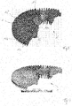
- a heatsink 1 in traditional configuration is shown in Figure 2 .
- the heatsink 1 is integrally formed and thus both parts of the heatsink 1 to which the light source 2 and the driver housing 5 are attached are connected with each other.
- this connection is realized by the radially extending cooling fins 15 which extend from the central opening 1a of the heatsink 1 to its circumference.
- These cooling fins 15, on the other not only mechanically couple both regions of the heatsink 1 with each other but also result in a thermal coupling between both regions. Heat generated by the light source 2 can thus be transferred in the center region surrounding the driver 3 and vice versa.
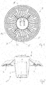
- the inventive heatsink 1 of Figure 3 is similar to the one shown in Figure 2 but has been adapted to prevent the cooling fins 15 from transferring heat from the light source 2 to the center region where the driver housing 5 is arranged.
- the inventive further development can be seen when comparing both figures. While the heatsink 1 of Figure 2 comprises several cooling fins 15 extending from the center region to the circumference of the heatsink 1, most of this fins 15 are in the inventive embodiment of Figure 3 interrupted by a gap 16.
- This gap 16 divides the cooling fins 15 in a first portion 15a extending from the center region outwardly and a second portion 15b extending from the circumference of the heatsink 1 inwardly. Both cooling fin portions 15a and 15b are aligned with each other but prevented from exchanging heat by the gap 16.
- the size and location of the gaps 16 can be adapted according to the actual design of the heatsink 1. However, since the gap 16 reduces the surface of the corresponding cooling fin 15, it is preferred that the gap width of the gap 16 is small. On the other hand, a minimum width of the gap 16 is required to block a heat transfer from one portion of the fin 15 to the other. Accordingly, the width of the gap 16 is preferably in the rage between 3mm and 7mm, in particular around 5mm.
- the gap 16 is preferably located closer to the center region, i.e., the outer portion 15b of the cooling fin 15 being responsible for cooling the LED light sources 2 is larger than the inner portion 15a which is responsible for removing heat from the driver 3.
- the length ratio of both cooling fin portions 15a, 15b is around 1:4 but can be adapted in case the design of the heatsink 1 and/or the amount of heat generated by the LED light source 2 is changed.
- fin-like support elements 20 integrally extend from the center region to the outer region of the heatsink 1 where the LED light sources 2 are arranged. These support elements 20 are required to integrally connect the outer part with the inner part of the heatsink 1 which otherwise would be split in two separate components. A design of the heatsink 1 in one piece is, however, preferred with respect to the mounting of the complete luminaire 10. On the other hand, the total number of such support elements 20 should be kept low since these elements 20 again increase the thermal coupling between both regions of the heatsink 1. In the embodiment shown in the Figures, 4 support elements 20 are used.
- a diagonal cut 21 splits each support element 20 in an upper portion 20a and a lower portion 20b. While the upper portion 20a extends from an upper area of the central portion to the outer region of the heatsink 1, the lower portion 20b merely projects outwardly with a triangular shape from the circumference of the central opening 1a but is not in contact with LED light sources 2.
- the upper portion 20a further comprises the shown stepped configuration resulting in a minimum amount of material which thermally connects the outer portion of the heatsink 1 with the inner portion.
- the inventive structure of the heatsink 1 helps to avoid the heat transfer problems mentioned above.
- overheating of an LED driver or other components required for an emergency lighting can be avoided even in situations where the luminaire is operated at high ambient temperatures.
- the shown heatsink can be adapted in several aspects without departing from the inventive concept.
- the idea of using an integral heatsink for cooling both a light source and a driver but avoiding or at least suppressing a transfer of heat between both regions of the heatsink could also be realized in longitudinal heatsink designs or other structures.
Landscapes
- Engineering & Computer Science (AREA)
- General Engineering & Computer Science (AREA)
- Arrangement Of Elements, Cooling, Sealing, Or The Like Of Lighting Devices (AREA)
- Non-Portable Lighting Devices Or Systems Thereof (AREA)
Claims (12)
- Kühlkörper (l) für einen Beleuchtungskörper (10), der Kühlkörper (1) umfassend• einen ersten Abschnitt, der für das Anordnen eines Lichtquellentreibers (3), einer Notbeleuchtungseinheit oder eines Gehäuses (5) zur Unterbringung eines Lichtquellentreibers (3) oder einer Notbeleuchtungseinheit angeordnet ist, und• einen zweiten Abschnitt, der mit dem ersten Abschnitt einstückig ausgebildet und für das Anordnen einer Lichtquelle (2) angepasst ist,wobei mindestens einige Kühlrippen (15), die sich vom ersten Abschnitt zum zweiten Abschnitt erstrecken, durch einen Spalt (16) unterbrochen werden, dadurch gekennzeichnet, dass der Kühlkörper (1) ferner Stützelemente (20) umfasst, die sich vom ersten Abschnitt des Kühlkörpers (1) zum zweiten Abschnitt erstrecken,
wobei die Stützelemente (20) einen Schnitt (21) umfassen, der jedes Stützelement (20) in zwei Abschnitte (20a, 20b) teilt, und wobei der Schnitt (21) sich diagonal durch das Stützelement (20) erstreckt. - Kühlkörper nach Anspruch 1,
wobei jeder Spalt (16) eine entsprechende Kühlrippe (15) in einen ersten Kühlrippenabschnitt (15a) und einen zweiten Kühlrippenabschnitt (15b) teilt, wobei beide Abschnitte miteinander ausgerichtet sind. - Kühlkörper nach Anspruch 2,
wobei der Spalt (16) beide Kühlrippenabschnitte (15a, 15b) um einen Abstand von etwa 3 bis 7 mm, bevorzugt um etwa 5 mm, trennt. - Kühlkörper nach Anspruch 2 oder 3,
wobei das Längenverhältnis zwischen dem ersten Kühlrippenabschnitt (15a) und dem zweiten Kühlrippenabschnitt (15b) etwa 1:4 ist. - Kühlkörper nach einem der vorhergehenden Abschnitte,
wobei der Kühlkörper (1) eine kreisförmige Konfiguration aufweist, bei der der erste Abschnitt einen zentralen Abschnitt des Kühlkörpers (1) ausbildet und der zweite Abschnitt einen äußeren Abschnitt ausbildet. - Kühlkörper nach Anspruch 5,
wobei die Kühlrippen (15) sich vom ersten Abschnitt des Kühlkörpers (1) zum zweiten Abschnitt radial nach außen erstrecken, wobei die Kühlrippen (15) bevorzugt gleichmäßig über den Umfang des Kühlkörpers (1) verteilt sind. - Kühlkörper nach Anspruch 5 oder 6,
wobei der Kühlkörper (1) ein zentrales Loch (1a) umfasst, das für die Kombination mit einem Gehäuse (5) zur Unterbringung eines Lichtquellentreibers (3) oder einer Notbeleuchtungseinheit angepasst ist. - Kühlkörper nach einem der Ansprüche 5 bis 7,
wobei der Kühlkörper (1) eine Aufnahmenut (1d), z. B. eine sich am Umfang erstreckende Aufnahmenut, für das Aufnehmen der Lichtquelle (2) umfasst. - Kühlkörper nach einem der Ansprüche 1 bis 4,
wobei der Kühlkörper (1) eine Längskonfiguration aufweist, bei der sich beide Abschnitte parallel zueinander erstrecken. - Kühlkörper nach Anspruch 9,
wobei der Kühlkörper (1) einen weiteren zweiten Abschnitt für das Anpassen zum Anordnen einer Lichtquelle umfasst,
wobei der erste Abschnitt sich zwischen beiden zweiten Abschnitten erstreckt. - Ein Beleuchtungskörper (10) mit einer Hauptstrahlrichtung (B), umfassend:
einen Kühlkörper (1) nach einem der vorhergehenden Abschnitte, eine Lichtquelle (2), die am Kühlkörper (1) montiert ist, und einen Treiber (3), der konfiguriert ist, die Lichtquelle (2) anzutreiben. - Beleuchtungskörper nach Anspruch 11,
wobei die Lichtquelle (2) eine LED-Lichtquelle ist.
Priority Applications (1)
| Application Number | Priority Date | Filing Date | Title |
|---|---|---|---|
| EP16186226.3A EP3290790B1 (de) | 2016-08-30 | 2016-08-30 | Kühlkörper |
Applications Claiming Priority (1)
| Application Number | Priority Date | Filing Date | Title |
|---|---|---|---|
| EP16186226.3A EP3290790B1 (de) | 2016-08-30 | 2016-08-30 | Kühlkörper |
Publications (2)
| Publication Number | Publication Date |
|---|---|
| EP3290790A1 EP3290790A1 (de) | 2018-03-07 |
| EP3290790B1 true EP3290790B1 (de) | 2019-04-10 |
Family
ID=56883562
Family Applications (1)
| Application Number | Title | Priority Date | Filing Date |
|---|---|---|---|
| EP16186226.3A Not-in-force EP3290790B1 (de) | 2016-08-30 | 2016-08-30 | Kühlkörper |
Country Status (1)
| Country | Link |
|---|---|
| EP (1) | EP3290790B1 (de) |
Families Citing this family (2)
| Publication number | Priority date | Publication date | Assignee | Title |
|---|---|---|---|---|
| DE202019100275U1 (de) * | 2019-01-18 | 2020-04-23 | Zumtobel Lighting Gmbh | Leuchte mit umfangsseitig geschlossenem Kühlkörper |
| IT202200005645A1 (it) * | 2022-03-22 | 2023-09-22 | Cortem S P A | Apparato di illuminazione e relativo procedimento d’uso |
Family Cites Families (7)
| Publication number | Priority date | Publication date | Assignee | Title |
|---|---|---|---|---|
| US20100226139A1 (en) * | 2008-12-05 | 2010-09-09 | Permlight Products, Inc. | Led-based light engine |
| KR20110001434U (ko) * | 2009-08-04 | 2011-02-10 | 김민공 | 엘이디 조명등 |
| JP2012015148A (ja) * | 2010-06-29 | 2012-01-19 | Rohm Co Ltd | Ledモジュールおよびled照明装置 |
| US20130294083A1 (en) * | 2011-01-26 | 2013-11-07 | Kuan Tech (Beihai) Co., Ltd. | LED Street Lamp with Improved Heat Dissipation |
| FR2981731B1 (fr) * | 2011-10-20 | 2016-03-25 | Epled France | Dispositif d'eclairage a diodes electroluminescentes |
| EP2806209B1 (de) * | 2013-05-24 | 2019-03-20 | Holophane Europe Ltd. | LED-Leuchte mit mehreren Belüftungsöffnungen zur Förderung der vertikalen Belüftung |
| CN106662321A (zh) * | 2014-06-03 | 2017-05-10 | 飞利浦灯具控股公司 | 照明器散热器 |
-
2016
- 2016-08-30 EP EP16186226.3A patent/EP3290790B1/de not_active Not-in-force
Non-Patent Citations (1)
| Title |
|---|
| None * |
Also Published As
| Publication number | Publication date |
|---|---|
| EP3290790A1 (de) | 2018-03-07 |
Similar Documents
| Publication | Publication Date | Title |
|---|---|---|
| US7771082B2 (en) | Lamp with heat conducting structure and lamp cover thereof | |
| US7857486B2 (en) | LED lamp assembly having heat pipes and finned heat sinks | |
| US7663229B2 (en) | Lighting device | |
| US8740415B2 (en) | Partitioned heatsink for improved cooling of an LED bulb | |
| EP2929240B1 (de) | Flache beleuchtungsvorrichtung | |
| US8702278B2 (en) | LED lighting apparatus with flexible light modules | |
| US7794115B2 (en) | Illumination unit | |
| CN101619822B (zh) | 照明装置 | |
| EP1826480B1 (de) | Beleuchtungsvorrichtung | |
| US9638409B2 (en) | LED lamp | |
| US9482391B2 (en) | Omnidirectional LED bulb | |
| KR20100117023A (ko) | 조명장치 | |
| US20100220487A1 (en) | Lighting assembly and heat exchange apparatus for uniform heat dissipation | |
| EP1998101B1 (de) | Beleuchtungsvorrichtung | |
| WO2011137355A1 (en) | A cooling structure for led lamps | |
| US20110069500A1 (en) | Heat Dissipation Module For Bulb Type LED Lamp | |
| US12152753B2 (en) | Lamp | |
| EP3290790A1 (de) | Kühlkörper | |
| WO2012056270A1 (en) | An improved light emitting diode spotlight | |
| EP3279558B1 (de) | Leuchte | |
| JP5624391B2 (ja) | 照明器具の放熱構造 | |
| US10125966B2 (en) | Light emitting diode lamps with heat-dispersing construction and mechanism | |
| EP2573450B1 (de) | Flughafen- und Hubschrauberlandeplatzbeleuchtungssystem | |
| KR20170129010A (ko) | 차량용 램프의 led 광원 모듈 | |
| WO2010094178A1 (en) | Lighting assembly and heat exchange apparatus for uniform heat dissipation |
Legal Events
| Date | Code | Title | Description |
|---|---|---|---|
| PUAI | Public reference made under article 153(3) epc to a published international application that has entered the european phase |
Free format text: ORIGINAL CODE: 0009012 |
|
| STAA | Information on the status of an ep patent application or granted ep patent |
Free format text: STATUS: THE APPLICATION HAS BEEN PUBLISHED |
|
| AK | Designated contracting states |
Kind code of ref document: A1 Designated state(s): AL AT BE BG CH CY CZ DE DK EE ES FI FR GB GR HR HU IE IS IT LI LT LU LV MC MK MT NL NO PL PT RO RS SE SI SK SM TR |
|
| AX | Request for extension of the european patent |
Extension state: BA ME |
|
| STAA | Information on the status of an ep patent application or granted ep patent |
Free format text: STATUS: REQUEST FOR EXAMINATION WAS MADE |
|
| 17P | Request for examination filed |
Effective date: 20180822 |
|
| RBV | Designated contracting states (corrected) |
Designated state(s): AL AT BE BG CH CY CZ DE DK EE ES FI FR GB GR HR HU IE IS IT LI LT LU LV MC MK MT NL NO PL PT RO RS SE SI SK SM TR |
|
| GRAP | Despatch of communication of intention to grant a patent |
Free format text: ORIGINAL CODE: EPIDOSNIGR1 |
|
| STAA | Information on the status of an ep patent application or granted ep patent |
Free format text: STATUS: GRANT OF PATENT IS INTENDED |
|
| RIC1 | Information provided on ipc code assigned before grant |
Ipc: F21Y 115/10 20160101ALN20181116BHEP Ipc: F21V 29/77 20150101ALI20181116BHEP Ipc: F21Y 105/18 20160101ALN20181116BHEP Ipc: F21V 23/00 20150101ALN20181116BHEP Ipc: F21V 29/508 20150101AFI20181116BHEP |
|
| INTG | Intention to grant announced |
Effective date: 20181217 |
|
| GRAS | Grant fee paid |
Free format text: ORIGINAL CODE: EPIDOSNIGR3 |
|
| GRAA | (expected) grant |
Free format text: ORIGINAL CODE: 0009210 |
|
| STAA | Information on the status of an ep patent application or granted ep patent |
Free format text: STATUS: THE PATENT HAS BEEN GRANTED |
|
| AK | Designated contracting states |
Kind code of ref document: B1 Designated state(s): AL AT BE BG CH CY CZ DE DK EE ES FI FR GB GR HR HU IE IS IT LI LT LU LV MC MK MT NL NO PL PT RO RS SE SI SK SM TR |
|
| REG | Reference to a national code |
Ref country code: GB Ref legal event code: FG4D |
|
| REG | Reference to a national code |
Ref country code: CH Ref legal event code: EP Ref country code: AT Ref legal event code: REF Ref document number: 1119182 Country of ref document: AT Kind code of ref document: T Effective date: 20190415 |
|
| REG | Reference to a national code |
Ref country code: IE Ref legal event code: FG4D |
|
| REG | Reference to a national code |
Ref country code: DE Ref legal event code: R096 Ref document number: 602016012143 Country of ref document: DE |
|
| REG | Reference to a national code |
Ref country code: NL Ref legal event code: MP Effective date: 20190410 |
|
| REG | Reference to a national code |
Ref country code: LT Ref legal event code: MG4D |
|
| PG25 | Lapsed in a contracting state [announced via postgrant information from national office to epo] |
Ref country code: NL Free format text: LAPSE BECAUSE OF FAILURE TO SUBMIT A TRANSLATION OF THE DESCRIPTION OR TO PAY THE FEE WITHIN THE PRESCRIBED TIME-LIMIT Effective date: 20190410 |
|
| PG25 | Lapsed in a contracting state [announced via postgrant information from national office to epo] |
Ref country code: ES Free format text: LAPSE BECAUSE OF FAILURE TO SUBMIT A TRANSLATION OF THE DESCRIPTION OR TO PAY THE FEE WITHIN THE PRESCRIBED TIME-LIMIT Effective date: 20190410 Ref country code: AL Free format text: LAPSE BECAUSE OF FAILURE TO SUBMIT A TRANSLATION OF THE DESCRIPTION OR TO PAY THE FEE WITHIN THE PRESCRIBED TIME-LIMIT Effective date: 20190410 Ref country code: SE Free format text: LAPSE BECAUSE OF FAILURE TO SUBMIT A TRANSLATION OF THE DESCRIPTION OR TO PAY THE FEE WITHIN THE PRESCRIBED TIME-LIMIT Effective date: 20190410 Ref country code: LT Free format text: LAPSE BECAUSE OF FAILURE TO SUBMIT A TRANSLATION OF THE DESCRIPTION OR TO PAY THE FEE WITHIN THE PRESCRIBED TIME-LIMIT Effective date: 20190410 Ref country code: PT Free format text: LAPSE BECAUSE OF FAILURE TO SUBMIT A TRANSLATION OF THE DESCRIPTION OR TO PAY THE FEE WITHIN THE PRESCRIBED TIME-LIMIT Effective date: 20190910 Ref country code: HR Free format text: LAPSE BECAUSE OF FAILURE TO SUBMIT A TRANSLATION OF THE DESCRIPTION OR TO PAY THE FEE WITHIN THE PRESCRIBED TIME-LIMIT Effective date: 20190410 Ref country code: FI Free format text: LAPSE BECAUSE OF FAILURE TO SUBMIT A TRANSLATION OF THE DESCRIPTION OR TO PAY THE FEE WITHIN THE PRESCRIBED TIME-LIMIT Effective date: 20190410 Ref country code: NO Free format text: LAPSE BECAUSE OF FAILURE TO SUBMIT A TRANSLATION OF THE DESCRIPTION OR TO PAY THE FEE WITHIN THE PRESCRIBED TIME-LIMIT Effective date: 20190710 |
|
| PG25 | Lapsed in a contracting state [announced via postgrant information from national office to epo] |
Ref country code: GR Free format text: LAPSE BECAUSE OF FAILURE TO SUBMIT A TRANSLATION OF THE DESCRIPTION OR TO PAY THE FEE WITHIN THE PRESCRIBED TIME-LIMIT Effective date: 20190711 Ref country code: RS Free format text: LAPSE BECAUSE OF FAILURE TO SUBMIT A TRANSLATION OF THE DESCRIPTION OR TO PAY THE FEE WITHIN THE PRESCRIBED TIME-LIMIT Effective date: 20190410 Ref country code: PL Free format text: LAPSE BECAUSE OF FAILURE TO SUBMIT A TRANSLATION OF THE DESCRIPTION OR TO PAY THE FEE WITHIN THE PRESCRIBED TIME-LIMIT Effective date: 20190410 Ref country code: LV Free format text: LAPSE BECAUSE OF FAILURE TO SUBMIT A TRANSLATION OF THE DESCRIPTION OR TO PAY THE FEE WITHIN THE PRESCRIBED TIME-LIMIT Effective date: 20190410 Ref country code: BG Free format text: LAPSE BECAUSE OF FAILURE TO SUBMIT A TRANSLATION OF THE DESCRIPTION OR TO PAY THE FEE WITHIN THE PRESCRIBED TIME-LIMIT Effective date: 20190710 |
|
| PG25 | Lapsed in a contracting state [announced via postgrant information from national office to epo] |
Ref country code: IS Free format text: LAPSE BECAUSE OF FAILURE TO SUBMIT A TRANSLATION OF THE DESCRIPTION OR TO PAY THE FEE WITHIN THE PRESCRIBED TIME-LIMIT Effective date: 20190810 |
|
| REG | Reference to a national code |
Ref country code: DE Ref legal event code: R097 Ref document number: 602016012143 Country of ref document: DE |
|
| PG25 | Lapsed in a contracting state [announced via postgrant information from national office to epo] |
Ref country code: DK Free format text: LAPSE BECAUSE OF FAILURE TO SUBMIT A TRANSLATION OF THE DESCRIPTION OR TO PAY THE FEE WITHIN THE PRESCRIBED TIME-LIMIT Effective date: 20190410 Ref country code: SK Free format text: LAPSE BECAUSE OF FAILURE TO SUBMIT A TRANSLATION OF THE DESCRIPTION OR TO PAY THE FEE WITHIN THE PRESCRIBED TIME-LIMIT Effective date: 20190410 Ref country code: RO Free format text: LAPSE BECAUSE OF FAILURE TO SUBMIT A TRANSLATION OF THE DESCRIPTION OR TO PAY THE FEE WITHIN THE PRESCRIBED TIME-LIMIT Effective date: 20190410 Ref country code: CZ Free format text: LAPSE BECAUSE OF FAILURE TO SUBMIT A TRANSLATION OF THE DESCRIPTION OR TO PAY THE FEE WITHIN THE PRESCRIBED TIME-LIMIT Effective date: 20190410 Ref country code: EE Free format text: LAPSE BECAUSE OF FAILURE TO SUBMIT A TRANSLATION OF THE DESCRIPTION OR TO PAY THE FEE WITHIN THE PRESCRIBED TIME-LIMIT Effective date: 20190410 |
|
| PLBE | No opposition filed within time limit |
Free format text: ORIGINAL CODE: 0009261 |
|
| STAA | Information on the status of an ep patent application or granted ep patent |
Free format text: STATUS: NO OPPOSITION FILED WITHIN TIME LIMIT |
|
| PG25 | Lapsed in a contracting state [announced via postgrant information from national office to epo] |
Ref country code: IT Free format text: LAPSE BECAUSE OF FAILURE TO SUBMIT A TRANSLATION OF THE DESCRIPTION OR TO PAY THE FEE WITHIN THE PRESCRIBED TIME-LIMIT Effective date: 20190410 Ref country code: SM Free format text: LAPSE BECAUSE OF FAILURE TO SUBMIT A TRANSLATION OF THE DESCRIPTION OR TO PAY THE FEE WITHIN THE PRESCRIBED TIME-LIMIT Effective date: 20190410 |
|
| 26N | No opposition filed |
Effective date: 20200113 |
|
| PG25 | Lapsed in a contracting state [announced via postgrant information from national office to epo] |
Ref country code: TR Free format text: LAPSE BECAUSE OF FAILURE TO SUBMIT A TRANSLATION OF THE DESCRIPTION OR TO PAY THE FEE WITHIN THE PRESCRIBED TIME-LIMIT Effective date: 20190410 |
|
| PG25 | Lapsed in a contracting state [announced via postgrant information from national office to epo] |
Ref country code: MC Free format text: LAPSE BECAUSE OF FAILURE TO SUBMIT A TRANSLATION OF THE DESCRIPTION OR TO PAY THE FEE WITHIN THE PRESCRIBED TIME-LIMIT Effective date: 20190410 Ref country code: LI Free format text: LAPSE BECAUSE OF NON-PAYMENT OF DUE FEES Effective date: 20190831 Ref country code: SI Free format text: LAPSE BECAUSE OF FAILURE TO SUBMIT A TRANSLATION OF THE DESCRIPTION OR TO PAY THE FEE WITHIN THE PRESCRIBED TIME-LIMIT Effective date: 20190410 Ref country code: CH Free format text: LAPSE BECAUSE OF NON-PAYMENT OF DUE FEES Effective date: 20190831 Ref country code: LU Free format text: LAPSE BECAUSE OF NON-PAYMENT OF DUE FEES Effective date: 20190830 |
|
| REG | Reference to a national code |
Ref country code: BE Ref legal event code: MM Effective date: 20190831 |
|
| PG25 | Lapsed in a contracting state [announced via postgrant information from national office to epo] |
Ref country code: IE Free format text: LAPSE BECAUSE OF NON-PAYMENT OF DUE FEES Effective date: 20190830 |
|
| PG25 | Lapsed in a contracting state [announced via postgrant information from national office to epo] |
Ref country code: BE Free format text: LAPSE BECAUSE OF NON-PAYMENT OF DUE FEES Effective date: 20190831 |
|
| PG25 | Lapsed in a contracting state [announced via postgrant information from national office to epo] |
Ref country code: CY Free format text: LAPSE BECAUSE OF FAILURE TO SUBMIT A TRANSLATION OF THE DESCRIPTION OR TO PAY THE FEE WITHIN THE PRESCRIBED TIME-LIMIT Effective date: 20190410 |
|
| PG25 | Lapsed in a contracting state [announced via postgrant information from national office to epo] |
Ref country code: MT Free format text: LAPSE BECAUSE OF FAILURE TO SUBMIT A TRANSLATION OF THE DESCRIPTION OR TO PAY THE FEE WITHIN THE PRESCRIBED TIME-LIMIT Effective date: 20190410 Ref country code: HU Free format text: LAPSE BECAUSE OF FAILURE TO SUBMIT A TRANSLATION OF THE DESCRIPTION OR TO PAY THE FEE WITHIN THE PRESCRIBED TIME-LIMIT; INVALID AB INITIO Effective date: 20160830 |
|
| REG | Reference to a national code |
Ref country code: AT Ref legal event code: UEP Ref document number: 1119182 Country of ref document: AT Kind code of ref document: T Effective date: 20190410 |
|
| PG25 | Lapsed in a contracting state [announced via postgrant information from national office to epo] |
Ref country code: MK Free format text: LAPSE BECAUSE OF FAILURE TO SUBMIT A TRANSLATION OF THE DESCRIPTION OR TO PAY THE FEE WITHIN THE PRESCRIBED TIME-LIMIT Effective date: 20190410 |
|
| REG | Reference to a national code |
Ref country code: AT Ref legal event code: MM01 Ref document number: 1119182 Country of ref document: AT Kind code of ref document: T Effective date: 20210830 |
|
| PG25 | Lapsed in a contracting state [announced via postgrant information from national office to epo] |
Ref country code: AT Free format text: LAPSE BECAUSE OF NON-PAYMENT OF DUE FEES Effective date: 20210830 |
|
| P01 | Opt-out of the competence of the unified patent court (upc) registered |
Effective date: 20230530 |
|
| REG | Reference to a national code |
Ref country code: DE Ref legal event code: R084 Ref document number: 602016012143 Country of ref document: DE |
|
| PGFP | Annual fee paid to national office [announced via postgrant information from national office to epo] |
Ref country code: GB Payment date: 20230822 Year of fee payment: 8 |
|
| PGFP | Annual fee paid to national office [announced via postgrant information from national office to epo] |
Ref country code: FR Payment date: 20230824 Year of fee payment: 8 |
|
| PGFP | Annual fee paid to national office [announced via postgrant information from national office to epo] |
Ref country code: DE Payment date: 20240828 Year of fee payment: 9 |
|
| GBPC | Gb: european patent ceased through non-payment of renewal fee |
Effective date: 20240830 |
|
| PG25 | Lapsed in a contracting state [announced via postgrant information from national office to epo] |
Ref country code: GB Free format text: LAPSE BECAUSE OF NON-PAYMENT OF DUE FEES Effective date: 20240830 |
|
| PG25 | Lapsed in a contracting state [announced via postgrant information from national office to epo] |
Ref country code: FR Free format text: LAPSE BECAUSE OF NON-PAYMENT OF DUE FEES Effective date: 20240831 |
|
| REG | Reference to a national code |
Ref country code: DE Ref legal event code: R119 Ref document number: 602016012143 Country of ref document: DE |