EP3290796A1 - Procédé de commande d'un rapport air-combustible dans un système de chauffage et unité de commande et système de chauffage - Google Patents
Procédé de commande d'un rapport air-combustible dans un système de chauffage et unité de commande et système de chauffage Download PDFInfo
- Publication number
- EP3290796A1 EP3290796A1 EP17185688.3A EP17185688A EP3290796A1 EP 3290796 A1 EP3290796 A1 EP 3290796A1 EP 17185688 A EP17185688 A EP 17185688A EP 3290796 A1 EP3290796 A1 EP 3290796A1
- Authority
- EP
- European Patent Office
- Prior art keywords
- fuel
- heating system
- fluid supply
- parameter
- combustion
- Prior art date
- Legal status (The legal status is an assumption and is not a legal conclusion. Google has not performed a legal analysis and makes no representation as to the accuracy of the status listed.)
- Granted
Links
Images

Classifications
-
- F—MECHANICAL ENGINEERING; LIGHTING; HEATING; WEAPONS; BLASTING
- F23—COMBUSTION APPARATUS; COMBUSTION PROCESSES
- F23N—REGULATING OR CONTROLLING COMBUSTION
- F23N1/00—Regulating fuel supply
- F23N1/002—Regulating fuel supply using electronic means
-
- F—MECHANICAL ENGINEERING; LIGHTING; HEATING; WEAPONS; BLASTING
- F23—COMBUSTION APPARATUS; COMBUSTION PROCESSES
- F23N—REGULATING OR CONTROLLING COMBUSTION
- F23N5/00—Systems for controlling combustion
- F23N5/02—Systems for controlling combustion using devices responsive to thermal changes or to thermal expansion of a medium
- F23N5/12—Systems for controlling combustion using devices responsive to thermal changes or to thermal expansion of a medium using ionisation-sensitive elements, i.e. flame rods
- F23N5/123—Systems for controlling combustion using devices responsive to thermal changes or to thermal expansion of a medium using ionisation-sensitive elements, i.e. flame rods using electronic means
-
- F—MECHANICAL ENGINEERING; LIGHTING; HEATING; WEAPONS; BLASTING
- F23—COMBUSTION APPARATUS; COMBUSTION PROCESSES
- F23N—REGULATING OR CONTROLLING COMBUSTION
- F23N2227/00—Ignition or checking
- F23N2227/20—Calibrating devices
-
- F—MECHANICAL ENGINEERING; LIGHTING; HEATING; WEAPONS; BLASTING
- F23—COMBUSTION APPARATUS; COMBUSTION PROCESSES
- F23N—REGULATING OR CONTROLLING COMBUSTION
- F23N2233/00—Ventilators
- F23N2233/06—Ventilators at the air intake
- F23N2233/08—Ventilators at the air intake with variable speed
Definitions
- the invention relates to a method for controlling a fuel-air ratio in a heating system.
- the invention also relates to a control unit which is designed to carry out the method according to the invention and to a heating system with the control unit according to the invention.
- heating system means at least one device for generating heat energy, in particular a heater or heating burner, in particular for use in a building heating and / or hot water generation, preferably by the combustion of a gaseous or liquid fuel.
- a heating system can also consist of several such devices for generating heat energy and other, the heating operation supporting devices, such as hot water and fuel storage.
- a "fluid supply parameter" is to be understood in particular to be a scalar parameter which is correlated in particular with at least one fluid, in particular a combustion unit of the heating system, in particular a combustion air flow, a fuel flow and / or a mixture flow, in particular from a combustion air and the fuel ,
- a control and / or regulating unit of the heating system at least on the basis of the fluid supply characteristic to a volume flow and / or a mass flow of the at least one fluid are closed and / or the flow rate and / or the mass flow of the at least one fluid can be determined.
- An example of a fluid supply parameter is the indication of an opening width of a fuel valve.
- a “temporary, temporal fluid supply change” should be understood to mean a time-limited variation of the fluid supply parameter, so that it deviates from a largely constant value of the fluid supply parameter before the start of the fluid supply change.
- the fluid supply parameter is first increased or decreased over the period of fluid supply change and then to the largely constant value of Fluid supply characteristic regulated before the start of Fluidzubowsung.
- the duration of the fluid supply change is preferably pulse-like and short compared with the intended time variations of the fluid supply characteristic variable that occur during normal operation of the heating system.
- a "pulse”, a “pulse-like change” or a “pulse-shaped signal” is to be understood as a course of a parameter which is brought from a first value within a limited period to at least a second value different from the first value.
- a “pulse” is sometimes referred to as “pulse”, especially in electrical engineering.
- combustion characteristic is to be understood in particular to be a scalar parameter which is correlated in particular with combustion, in particular of the mixture, in particular of the combustion air and the fuel.
- An example of a combustion characteristic is an ionization current which is measured at a flame of the heating system.
- the combustion parameter corresponds to at least one or precisely one measured value representing the combustion and / or characterizing the combustion parameter or can be unambiguously assigned to such a measured value.
- a measured value representing the combustion and / or characterizing a combustion signal in particular a light intensity, a pollutant emission, a temperature and / or advantageously an ionization signal.
- a relative signal maximum is the maximum amplitude of the combustion characteristic in a correlated with the temporal change of the fluid supply parameter Period less the largely constant amplitude of the combustion parameter before this period or the amplitude of the combustion characteristic at the beginning of this period to understand.
- the relative signal maximum is a measure of the change in the combustion characteristic due to the fluid supply change.
- faulty state is meant a state of the heating system in which the operation is not possible in the intended frame.
- faults and defects include a non-fully functioning blower or suddenly occurring or slowly progressing blockages in the flow path of a fuel-air mixture. Causes of such blockages are, for example, wind, dirt, deposits or corrosion.
- non-optimal operation are over or under load of the heating system or a non-optimal combustion in a combustion chamber of the heating system, for example by incorrectly set operating parameters and / or incorrectly set sensors for determining the fuel-air ratio.
- An "attempt" to determine a relative maximum signal of a temporal change of at least one combustion parameter correlated with the temporal fluid change should be understood as a method step in which a relative signal maximum of a temporal change correlated with the time fluid change is measured by at least one combustion parameter or is detected. Depending on the result or value of the relative signal maximum, it is optionally possible to select different subsequent steps in the further course of the method if this is necessary and / or desired.
- measuring the heating system is meant the single or repeated, in particular periodic setting of operating parameters of the heating system, so that the heating system can always fulfill the specified and / or requested performance to the full extent, in particular under varying internal and external conditions, in particular during wear processes and changing boundary and environmental conditions.
- operating parameters are to be understood as parameters which are used by the control of the heating system for controlling and monitoring processes taking place in the heating system. Examples of “operating parameters” are a blower speed or a blower speed characteristic or a flame ionization characteristic.
- calibrating the heating system is meant in particular a calibration process in which the sensor system for measuring the fuel-air ratio is readjusted.
- burner performance parameter should be understood in particular to mean a scalar parameter which is correlated with a power, in particular heating power, of the heating system.
- the power, in particular heating power, of the heating system can be determined at least on the basis of the burner power parameter.
- the burner performance parameter corresponds to at least one or precisely one measured value which reflects the power or can be unambiguously assigned to such a measured value.
- a measured value may be, for example, a temperature, an air flow rate, a blower control signal or a blower speed.
- the method is particularly reliable.
- malfunction and / or defects in the detection of the temporal change of at least one combustion parameter are taken into account in a timely manner in this way.
- the signal lower limit is selected as a function of the burner performance parameter, the correlation between the at least one combustion parameter and the fuel / air ratio is taken into account at a further point in the method. In this way, detection of a fault condition is further improved. Overall, this improves the reliability of the process.
- a “substantially opposite additional fluid supply change” is to be understood as meaning a fluid supply change in which the fluid supply parameter is varied in time so that the change in an average fluid supply rate caused by the fluid supply change is compensated.
- the additional Fluid supply change implemented by a substantially rectangular pulse having a substantially same signal width and a relative signal level, which largely corresponds to the magnitude of the relative signal height of the first substantially rectangular pulse of Fluidzuschreib selectedung and is negative.
- a "largely rectangular shape of the fluid supply change" is to be understood as meaning a temporal progression of the fluid supply parameter, in which the fluid supply parameter initially has a normal value. Subsequently, the fluid supply parameter is rapidly increased to a largely constant maximum supply value. Thereafter, the fluid supply characteristic is rapidly lowered to the normal value.
- This temporal course of the fluid supply parameter has a good approximation in the form of a rectangular function.
- Such a time profile of the fluid supply characteristic is usually referred to as a rectangular signal.
- the fluid supply parameter corresponds to a control signal for metering a fuel and / or the combustion air and / or a mixture of a fuel and combustion air, in this way no measurement of the fuel and / or the combustion air and / or a mixture of a fuel and combustion air or a Flow of these fluids needed. This simplifies the procedure and makes it robust against malfunctions.
- the at least one combustion parameter is determined by an ionization current measurement on a flame of the heating system, this is particularly advantageous because there is a functional relationship between the ionization current at a flame and the fuel-air ratio, which can be evaluated particularly favorably.
- the method is further improved when the burner performance parameter is or depends on a fan speed and / or a mass flow of combustion air and / or a mixture of a fuel and Combustion air is or depends on this and / or is a volume flow of combustion air and / or a mixture of a fuel and combustion air or depends on this and / or a duration of combustion air and / or a mixture of a fuel and combustion air or depends on this ,
- the fan speed can be easily and reliably determined and provides a good estimate of the burner performance.
- a mass flow and / or a volume flow of a combustion air and / or a mixture of a fuel and combustion air allow a particularly accurate estimation of the burner power.
- a transit time of a combustion air and / or a mixture of a fuel and combustion air can be determined particularly easily and inexpensively.
- the temporal fluid supply change has an at least substantially rectangular shape, this has the advantage that the temporal change of the at least one combustion parameter can be detected particularly easily. In this way, the reliability of the process is further enhanced.
- a "largely rectangular shape of the fluid supply change" is to be understood as meaning a temporal progression of the fluid supply parameter, in which the fluid supply parameter initially has a normal value. Subsequently, the fluid supply parameter is rapidly increased to a largely constant maximum supply value. Thereafter, the fluid supply characteristic is rapidly lowered to the normal value.
- This temporal course of the fluid supply parameter has a good approximation in the form of a rectangular function. Such a time profile of the fluid supply characteristic is usually referred to as a rectangular signal.
- control unit for a heating system, wherein the control unit is adapted to carry out the inventive method for controlling a fuel-air ratio in a heating system, has the advantage that by largely preventing a wrong Setting the fuel-air ratio increases the durability of the heating system, preventing malfunction and thus increasing safety. In addition, by avoiding unnecessary calibration operations, the wear of the heating system is lowered.
- a heating system with a control unit according to the invention with a metering device for a fuel and / or combustion air and / or for a mixture of a fuel and combustion air, as well as with an ionization probe on a flame and with a blower with variable fan speed has the advantage that in Operation of the heating system is a wrong adjustment of the fuel-air ratio is largely prevented. In this way, unforeseen, heavy loads on the heating system are avoided by, for example, too high burner temperatures and / or excessive fan speeds and / or excessive soot emissions and / or excessive vibration. This allows a cost-effective production of the heating system. In addition, fuel consumption is reduced and the life of the heating system is increased or the time interval between the required inspection intervals is reduced.
- the heating system has at least one metering device for a fuel and / or for combustion air and / or for a mixture of a fuel and combustion air, a temporal change of a fluid supply parameter is thus particularly easy to produce.
- a "dosing device” should be understood as meaning in particular one, in particular electrical and / or electronic, unit, in particular actuator unit, advantageous setting unit, which is provided for the at least one fluid, in particular the combustion air flow, the fuel flow and / or the mixture flow, in particular from the combustion air and the fuel to influence.
- the at least one doser is to provided to adjust, regulate and / or promote a volume flow and / or a mass flow, in particular the combustion air and / or the fuel.
- the dosing device for combustion air can advantageously be designed as a fan, in particular having a variable speed, and / or preferably as a fan, in particular a variable-speed fan.
- the fuel metering device can advantageously be designed as a fuel pump, in particular variable in flow rate, and / or preferably as a fuel valve, in particular variable in flow rate.
- the combustion air metering device and / or the fuel metering device are intended to modulate a heating power of the heater device.
- the heating system has an ionization probe on the flame of the heater, this realizes a particularly favorable and reliable sensor for measuring a combustion scan.
- Ionization detectors are commonly used in heaters for flame detection.
- the heating system has a fan with variable fan speed, a simple and robust means for setting and determining the performance of the heater is realized in this way.
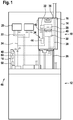
- FIG. 1 a heater 10 is shown schematically, which is arranged in the embodiment on a memory 12.
- the heater 10 has a housing 14 which accommodates different components depending on the degree of equipment.
- the essential components are a heat cell 16, a control unit 18, one or more pumps 20 and piping 22, cable or bus lines 24 and holding means 26 in the heater 10.
- the number and complexity of the individual components depends on the equipment level of the heater 10.
- the heat cell 16 includes a burner 28, a heat exchanger 30, a blower 32, a meter 34 and an air supply system 36, an exhaust system 38 and, when the heat cell 16 is in operation, a flame 40. In the flame 40 projects an ionization 42.
- the meter 34 is designed as a fuel valve 44.
- a blower speed 79 of the blower 32 is variably adjustable.
- the heater 10 and the memory 12 together form a heating system 46.
- the control unit 18 has a data memory 48, a computing unit 50 and a communication interface 52. Via the communication interface 52, the components of the heating system 46 can be controlled.
- the communication interface 52 allows data exchange with external devices. External devices are, for example, control devices, thermostats and / or devices with computer functionality, for example smartphones.
- FIG. 1 shows a heating system 46 with a control unit 18.
- the control unit 18 is located outside the housing 14 of the heater 10.
- the external control unit 18 is designed in particular variants as a room controller for the heating system 46.
- the control unit 18 is mobile.
- the external control unit 18 has a communication connection to the heater 10 and / or other components of the heating system 46.
- the communication connection can be wired and / or wireless, preferably a radio connection, particularly preferably via WLAN, Z-Wave, Bluetooth and / or ZigBee.
- the control unit 18 may consist of several components in other variants, in particular not physically connected components.
- At least one or more components of the control unit 18 may be partially or wholly in the form of software which is executed on internal or external devices, in particular on mobile computing units, for example smartphones and tablets, or servers, in particular a cloud.
- the communication connections are then corresponding software interfaces.
- FIG. 2 shows the method 54 according to the invention for controlling and regulating a fuel-air ratio 56 in a heating system 46.
- a temporal fluid supply change 60 of a fluid supply parameter 62 is generated in a step 58.
- the fluid supply parameter 62 is an intended opening width 64 of the metering device 34.
- the opening width 64 is a percentage, wherein an opening width 64 of 0% corresponds to a completely closed fuel valve 44 and an opening width 64 of 100% describes a fully opened fuel valve 44.
- the intended opening width 64 is realized by a selection of the control signal and transmission of this control signal to the fuel valve 44 by the control unit 18.
- the opening width 64 describes a request, which is transmitted to the fuel valve 44.
- the fluid supply change 60 is in FIG. 3 displayed.
- the first abscissa axis 66 represents a time.
- the ordinate axis 68 shows the fluid supply parameter 62.
- the fluid supply change 60 runs in a substantially rectangular pulse.
- the fluid supply characteristic 62 has a normal supply value 70.
- the opening width 64 is increased as fast as possible to a maximum supply value 72.
- the opening 64 is lowered to the normal supply value 70 as fast as possible.
- An in FIG. 3 Imaged pulse height 74 is 15%.
- An in FIG. 3 Imaged pulse width 76 is 120 ms.
- the fluid supply change 60 is dependent on a burner output parameter 77.
- the burner output parameter 77 is a fan speed 79.
- the fan speed 79 is a characteristic value determined by the control unit 18 which determines a fan control signal.
- the blower control signal is sent from the control unit 18 to the blower 32 and determines a speed of the blower 32.
- the pulse height 74 rises linearly with the blower speed 79. Between a minimal Blower speed and a maximum fan speed takes the pulse height 74 values in an interval between 10% and 20%.
- the pulse width 76 increases linearly with the fan speed 79. Between a minimum fan speed and a maximum fan speed, the pulse width 76 assumes values in an interval between 50 ms and 200 ms.
- a relative signal maximum 80 of a temporal change correlated with the temporal fluid supply change 60 from a combustion parameter 78.
- the combustion parameter 78 is an ionization stream 82.
- the ionization stream 82 is determined by the ionization probe 42 on the flame 40 and transmitted to the control unit 18.
- the time profile of the ionization current 82 has the relative signal maximum 80.
- the relative signal maximum 80 is determined from the difference between the absolute signal maximum 84 and the ionization current normal value 86 (see FIG. 3 ).
- the ionization current normal value 86 is determined in the exemplary embodiment in which the average ionization current 82 measured over the pulse width 76 is determined.
- the relative signal maximum 80 is determined, in which the ionization current 82 is measured over a determination time.
- the largest value of the ionization current 82 occurring within the determination time is selected as the absolute signal maximum 84.
- the determination time has the length of a time threshold 88 stored in the control unit 18.
- the determination time starts at a first time 90 and ends at a second time 92 (see FIG FIG. 3 ).
- the time threshold 88 is 2 seconds. In variants, a time threshold 88 between 1 second and 5 seconds is selected.
- a relative signal maximum 80 could be determined in step 75, the method continues with path C (see FIG. 2 ).
- a false state 96 is detected if the relative signal maximum 80 falls below a lower signal limit 98.
- the signal lower limit 98 is a constant stored in the control unit 18.
- the control unit 18 compares the relative signal maximum 80 with the signal lower limit 98. If the relative signal maximum 80 is smaller than the signal lower limit 98, a false state 96 is detected in which an error variable is set to the value 1.
- the method 54 continues on the path A (see FIG. 2 ). If the relative signal maximum 80 is greater than or equal to the lower signal limit 98, the error variable is set to the value 0 and the iteration of the method 54 is ended (path B in FIG FIG. 2 ).
- step 100 the heating system 46 is calibrated.
- the heating system 46 is driven in a special operating mode in which the sensors and analytics, in particular the ionization probe 42 and the ionization current 82 based, stored in the control unit 18 characteristics are adjusted and tuned. In this way, the determination of the fuel-air ratio 56 is specified. If necessary, during calibration of the heating system 46 in step 100, the heating system 46 or the processes and / or processes running on the heating system 46 are at least partially reinitialized or restarted.
- step 75 If no relative signal maximum 80 is determined in step 75, the method continues on the path D (see FIG. 2 ). In a step 101, a fault condition 96 is detected. The error variable is set to the value 1. The process 54 proceeds to step 100 and the heating system 46 is calibrated.
- FIG. 3 1 shows a change in the combustion parameter 78 following fluid supply change 60, which the next iteration of the process 54th belongs.
- a time interval between the iterations of the method 54 is selected depending on the operating state of the heating system 46 and the external conditions. In the exemplary embodiment, the time interval is between 1 second and 20 seconds, preferably 2 seconds.
- a fault status counter is stored in the control unit 18.
- the error counter is a variable which stores the number of detected failures 96 in a given time interval. If the fault condition counter exceeds a critical fault limit stored in the control unit 18, then the heating system 46 is shut down for safety reasons. The error counter is lowered after performing the method 54 without detecting a false state 96. In the exemplary embodiment, the heating system 46 is shut down after seven immediately consecutive determinations of a fault condition 96.
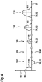
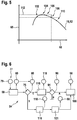
- FIGS. 4 and 5 illustrate the functional principle of the method 54.
- FIG. 4 is shown on a second abscissa axis 67 a time.
- On the ordinate axis 68 of the ionization 82 is plotted.
- the graphs of the ionization stream 82 each show temporal changes of the ionization stream 82 which occur due to a temporal fluid change 60 in various measurements 102, 104, 106, 108 and 110.
- the measurements are performed at a constant fan speed 79.
- Each of the measurements is performed at a different fuel-air ratio 56 (marked in FIG FIG. 5 ).
- the fuel-air ratio 56 is calculated from an amount of air divided by a fuel amount.
- FIG. 5 illustrates the relationship between the ionization flow 82 and the fuel-air ratio 56 at a constant fan speed 79.
- the ordinate axis 68 plots the ionization flow 82.
- the ionization current maximum 112 is increased or decreased starting from the maximum ionization current 112, the ionization current 82 decreases, with the magnitude of the slope increasing steadily.
- the heating system 46 is operated with a fuel-air ratio 56 of 1.3 (measurement 108), ie with an excess of air.
- the method 54 ensures that the heating system 46 is operated with excess air. If the fuel-air ratio 56 is less than 1 or the fuel-air ratio 56 is too close to the value 1, a fault condition 96 is detected.
- the fuel-air ratio 56 is briefly lowered. If the fuel-air ratio 56 is 0.85 (measurement 102), the fluid supply change 60 causes the ionization current 82 to decrease (see FIG FIG. 4 ). Thus, the relative signal maximum 80 is largely 0. The lower signal limit 98 is reached and a false state 96 detected. If the fuel-air ratio 56 is one (measurement 104), the fluid supply change 60 causes a slight decrease in the ionization current 82, since in this region the gradient of the graph of the ionization current 82 is approximately 0 and changes only slightly. In measurement 106, the fuel-air ratio 56 is 1.15. There is an excess of air, which is not sufficiently large.
- the fluid supply change 60 causes the ionization current 82 to increase.
- the relative signal maximum 80 is below the lower signal limit 98 because the magnitude of the slope of the ionization current graph 82 in the range of the fuel-air ratio 56 of the measurement 106 is too low. In measurements 108 and 110, the fuel-air ratio is 56 1.3 and 1.45, respectively. The excess air is sufficient in each case.
- the magnitude of the slope of the ionization current graph 82 is sufficiently large in the ranges of measurements 108 and 110.
- the fluid supply change 60 causes each increase of the ionization current 82.
- the relative signal maximum 80 is in each case greater than the lower signal limit 98. In the measurements 108 and 110, no false state 96 is detected.
- the relative signal maximum 80 between the first time 90 and the second time 92 is determined.
- the time threshold 88 is selected by means of laboratory tests such that under all operating conditions and boundary conditions, in particular at all fan speeds 79, the position of the maximum of the ionization current 82 always lies between the first time 90 and the second time 92. In alternative variants with a smaller time threshold 88, the maximum of the ionization current 82 may occur after the second time 92.
- the determined in step 75 relative maximum signal 80 is then possibly smaller than the actual maximum of the ionization stream 82, in particular at a low power of the heating system 46 and at low fan speeds 79. This is in preferred variants by a corresponding adjustment, in particular lowering of the signal lower limit 98th , in particular depending on the burner power parameter 77, taken into account.
- the temporal change of at least one combustion parameter 78 is determined, in which the occurrence of a pulse in the time course of the at least one combustion parameter 78 is detected.
- the relative signal maximum 80 is determined as the maximum value of the detected pulse. For this purpose, it is checked in step 75 by the control unit 18 whether, after the fluid supply change 60, the combustion parameter 78 increases beyond a signal noise.
- the relative signal maximum 80 is the maximum combustion parameter 78 in the time domain in which the combustion parameter 78 increases beyond a signal noise.
- the detection of the pulse over the course of time of the at least one combustion parameter 78 is ended if the determination time the time threshold exceeds 88 and no pulse could be detected. Then, no relative signal maximum 80 can be determined and the method 54 continues on the path D.
- step 75 is terminated as soon as the measured combustion parameter 78 exceeds the signal lower limit 98. Then the value of the relative signal maximum 80 is determined on the basis of the last measured combustion parameter 78 exceeding the lower signal limit 98. The process then proceeds to path C. If, in step 75, the measured combustion parameter 78 does not reach the signal lower limit 98 within the time threshold 88, the method continues with the path C.
- the time threshold 88 is a function of the burner performance parameter 77.
- the time threshold 88 has increased with a reduction in the performance of the heating system 46.
- the signal lower limit 98 is selected depending on the fan speed 79.
- a relative lower signal limit 114 is determined by the control unit 18 (see FIG. 3 ).
- the relative signal lower limit 114 is proportional to the negative fan speed 79. In this way, the higher signal noise of the ionization current 82 at low fan speeds 79 is taken into account.
- the relative lower signal limit 114 is 1 ⁇ A for the maximum fan speed 79 and 10 ⁇ A for the minimum fan speed 79.
- a relative lower signal limit 114 is selected between 3 ⁇ A and 7 ⁇ A.
- the signal lower limit 98 is determined from the sum of the relative lower signal limit 114 and the ionization current normal value 86.
- the ionization current normal value 86 decreases in the regular operation of the heating system 46 Values between 10 ⁇ A and 100 ⁇ A, in particular between 30 ⁇ A and 60 ⁇ A.
- the choice of the dependence of the signal lower limit 98 of the fan speed 79 and the burner performance parameter 77 depends on the technical characteristics of the heating system 46, in particular on the dependence of the signal noise of the ionization stream 82 and the combustion parameter 78 of the burner performance parameter 77.
- the relative lower signal limit 114 is constant.
- the relative signal lower limit is proportional to the burner performance parameter 77.
- the functional dependence of the relative lower signal limit 114 on the burner performance parameter 77 is substantially proportional to the functional dependence of a signal noise intensity of the ionization flow 82 on the burner performance parameter 77.
- an additional fluid supply change 118 is generated in an additional step 116.
- the additional fluid feed change 118 is substantially opposite to the fluid feed change 60.
- the mean fluid supply parameter 62 substantially corresponds to the normal supply value 70 over a period of the fluid supply change 60 and the additional fluid supply change 118.
- the graph of the time course of the fluid supply parameter 62 of the additional fluid supply change 118 is equal to the time-shifted graph of the normal supply value 70 Over time, the fluid supply characteristic 62 of the fluid supply change 60.
- the step 116 may be performed at any point in the process 54. In FIG.
- step 116 is positioned so that the additional fluid delivery change 118 is that associated with the fluid delivery change 60 correlated change in the combustion parameter 78 was not affected.
- Step 116 is preferably carried out after step 58, particularly preferably after step 75.
- the fluid supply parameter 62 is an opening width 64 of the fuel valve 44. Based on the intended opening width 64, the control unit 18 determines and transmits a control signal to the fuel valve 44.
- the fluid supply parameter 62 is a control signal to the fuel valve 44 or a scalar value derivable from the control signal.
- the fluid supply parameter 62 corresponds to a control signal for dosing a combustion air and / or a mixture of a fuel and a combustion air.
- the control signal sent by the control unit 18 is composed of at least one control command to at least one metering device 34.
- the at least one doser 34 is at least one fuel valve 44 and / or at least one blower 32.
- a dosage value of the doser 34 is measured and used as the fluid supply characteristic 62.
- dosage value is to be understood as a characteristic value which describes the state of the dosing device 34 and allows conclusions to be drawn about the amount of substance supplied and / or allowed to pass through the dosing device 34.
- An example of a dosage value is a measured opening width of the fuel valve 44 and / or a measured fuel flow.
- the combustion parameter 78 is an ionization stream 82.
- the ionization stream 82 is determined by an ionization current measurement on a flame 40 of the heating system 46.
- the ionization current 82 is determined by the ionization probe 42 and transmitted to the control unit 18.
- the combustion characteristic 78 is a Light intensity, a lambda value, a pollutant emissions and / or a temperature.
- the light intensity at the flame 40 is determined by a photodiode.
- the lambda value is measured with a lambda probe in an exhaust gas.
- the exhaust system 38 has the lambda probe.
- the pollutant emission is determined by a sensor device, which is located on the flame 40 and / or in the exhaust system 38.
- the temperature is determined by a contact thermometer and / or a non-contact thermometer, in particular a pyrometer. The thermometer may be located in the exhaust system 38 and / or the flame 40 measured.
- the burner output parameter 77 is the blower speed 79.
- the blower speed 79 is a characteristic value determined by the control unit 18, which determines a blower control signal.
- the burner performance parameter 77 is a measured fan speed and / or a temperature and / or an air flow rate and / or a flow rate of the air-fuel mixture.
- the air flow rate or the flow rate of the air-fuel mixture can be determined as a volume flow or as a mass flow.
- the burner performance parameter 77 is a transit time of a combustion air and / or a mixture of a fuel and combustion air.
- a transit time is determined as the time difference between the fluid supply change 60 and the change in the combustion characteristic 78 correlated with the fluid supply change 60.
- the transit time corresponds to the time it takes for the mixture of fuel and combustion air to pass from the fuel valve 44 to the ionization probe 42.
- the transit time is a measure of the flow rate of the air-fuel mixture.
- the fluid supply change 60 has a substantially rectangular shape.
- the fluid supply change 60 is substantially in the form of a ramp and / or largely a triangular shape and / or substantially the shape of a sine and / or largely a Gaussian shape.
- the change in a concentration of the fuel in the burner 28 resulting from the fluid supply change 60 generally has a different form than the fluid feed change 60.
- the fluid feed change 60 depends on the burner output parameter 77.
- the pulse height 74 and pulse width 76 each depend linearly on the fan speed 79. In this way it is ensured that the heating system 46 is not disturbed too much in its normal operation by the fluid supply change 60.
- the fluid supply change 60 has a functional relationship to the burner performance parameter 77.
- the functional relationship is chosen so that a good detection of the relative signal maximum 80 is possible taking into account the technical characteristics of the heating system 46. For example, if resonances occur at certain blower speeds 79, which increase the signal noise of the ionization flow 82, the fluid supply change 60 is increased at these blower speeds 79.
Landscapes
- Engineering & Computer Science (AREA)
- Chemical & Material Sciences (AREA)
- Combustion & Propulsion (AREA)
- Mechanical Engineering (AREA)
- General Engineering & Computer Science (AREA)
- Regulation And Control Of Combustion (AREA)
Applications Claiming Priority (2)
| Application Number | Priority Date | Filing Date | Title |
|---|---|---|---|
| DE102016216613 | 2016-09-02 | ||
| DE102017204012.2A DE102017204012A1 (de) | 2016-09-02 | 2017-03-10 | Verfahren zur Kontrolle eines Brennstoff-Luft-Verhältnisses in einem Heizsystem sowie eine Steuereinheit und ein Heizsystem |
Publications (2)
| Publication Number | Publication Date |
|---|---|
| EP3290796A1 true EP3290796A1 (fr) | 2018-03-07 |
| EP3290796B1 EP3290796B1 (fr) | 2021-01-27 |
Family
ID=59592882
Family Applications (1)
| Application Number | Title | Priority Date | Filing Date |
|---|---|---|---|
| EP17185688.3A Active EP3290796B1 (fr) | 2016-09-02 | 2017-08-10 | Procédé de commande d'un rapport air-combustible dans un système de chauffage et unité de commande et système de chauffage |
Country Status (1)
| Country | Link |
|---|---|
| EP (1) | EP3290796B1 (fr) |
Cited By (2)
| Publication number | Priority date | Publication date | Assignee | Title |
|---|---|---|---|---|
| EP3715716A1 (fr) * | 2019-03-29 | 2020-09-30 | Robert Bosch GmbH | Procédé de réglage et de commande d'un rapport air-combustible dans un système de chauffage ainsi qu'unité de commande et système de chauffage |
| DE102022100488A1 (de) | 2022-01-11 | 2023-07-13 | Vaillant Gmbh | Verfahren zum Betreiben eines flammenbildenden Heizgerätes einer Heizungsanlage, Computerprogramm, Speichermedium, Regel- und Steuergerät, Heizgerät und Verwendung einer Durchflussrate einer Heizungsanlage und eines Ionisationssignals eines Heizgerätes |
Citations (3)
| Publication number | Priority date | Publication date | Assignee | Title |
|---|---|---|---|---|
| DE102004004065A1 (de) * | 2003-01-30 | 2004-08-12 | Vaillant Gmbh | Verfahren und Vorrichtung zur vorbeugenden Fehlererkennung bei elektronisch geregelten oder gesteuerten Geräten |
| EP1923635A2 (fr) * | 2006-11-16 | 2008-05-21 | Robert Bosch GmbH | Procédé de pilotage d'un brûleur à gaz de type prémélange |
| DE102010055567A1 (de) * | 2010-12-21 | 2012-06-21 | Robert Bosch Gmbh | Verfahren zur Stabilisierung eines Betriebsverhaltens eines Gasgebläsebrenners |
Family Cites Families (3)
| Publication number | Priority date | Publication date | Assignee | Title |
|---|---|---|---|---|
| ATE189301T1 (de) * | 1995-10-25 | 2000-02-15 | Stiebel Eltron Gmbh & Co Kg | Verfahren und schaltung zur regelung eines gasbrenners |
| DE19831648B4 (de) * | 1998-07-15 | 2004-12-23 | Stiebel Eltron Gmbh & Co. Kg | Verfahren zur funktionalen Adaption einer Regelelektronik an ein Gasheizgerät |
| EP3156729B1 (fr) * | 2015-10-12 | 2019-03-20 | MHG Heiztechnik GmbH | Méthode de recalibration d'un brûleur pour carburant liquide |
-
2017
- 2017-08-10 EP EP17185688.3A patent/EP3290796B1/fr active Active
Patent Citations (3)
| Publication number | Priority date | Publication date | Assignee | Title |
|---|---|---|---|---|
| DE102004004065A1 (de) * | 2003-01-30 | 2004-08-12 | Vaillant Gmbh | Verfahren und Vorrichtung zur vorbeugenden Fehlererkennung bei elektronisch geregelten oder gesteuerten Geräten |
| EP1923635A2 (fr) * | 2006-11-16 | 2008-05-21 | Robert Bosch GmbH | Procédé de pilotage d'un brûleur à gaz de type prémélange |
| DE102010055567A1 (de) * | 2010-12-21 | 2012-06-21 | Robert Bosch Gmbh | Verfahren zur Stabilisierung eines Betriebsverhaltens eines Gasgebläsebrenners |
Cited By (2)
| Publication number | Priority date | Publication date | Assignee | Title |
|---|---|---|---|---|
| EP3715716A1 (fr) * | 2019-03-29 | 2020-09-30 | Robert Bosch GmbH | Procédé de réglage et de commande d'un rapport air-combustible dans un système de chauffage ainsi qu'unité de commande et système de chauffage |
| DE102022100488A1 (de) | 2022-01-11 | 2023-07-13 | Vaillant Gmbh | Verfahren zum Betreiben eines flammenbildenden Heizgerätes einer Heizungsanlage, Computerprogramm, Speichermedium, Regel- und Steuergerät, Heizgerät und Verwendung einer Durchflussrate einer Heizungsanlage und eines Ionisationssignals eines Heizgerätes |
Also Published As
| Publication number | Publication date |
|---|---|
| EP3290796B1 (fr) | 2021-01-27 |
Similar Documents
| Publication | Publication Date | Title |
|---|---|---|
| DE102017204009A1 (de) | Verfahren zur Kontrolle eines Brennstoff-Luft-Verhältnisses in einem Heizsystem sowie eine Steuereinheit und ein Heizsystem | |
| DE102017204012A1 (de) | Verfahren zur Kontrolle eines Brennstoff-Luft-Verhältnisses in einem Heizsystem sowie eine Steuereinheit und ein Heizsystem | |
| EP3290797B1 (fr) | Procédé de détection d'un état de vieillissement d'un système de chauffage ainsi qu'une unité de commande et système de chauffage | |
| EP3825623B1 (fr) | Appareil chauffant à réglage de mode d'urgence | |
| EP3290798B1 (fr) | Procédé de réglage et de commande d'un rapport air-combustible dans un système de chauffage ainsi qu'unité de commande et système de chauffage | |
| WO2016188677A1 (fr) | Système pour appareil de chauffage et procédé permettant de faire fonctionner un système pour appareil de chauffage | |
| EP2017531B1 (fr) | Procédé de vérification d'un signal issu d'électrodes d'ionisation pour brûleurs | |
| EP3290796B1 (fr) | Procédé de commande d'un rapport air-combustible dans un système de chauffage et unité de commande et système de chauffage | |
| DE102017204003A1 (de) | Verfahren zur Einstellung und Regelung eines Brennstoff-Luft-Verhältnisses in einem Heizsystem sowie eine Steuereinheit und ein Heizsystem | |
| DE102011111453A1 (de) | Verfahren zur Luftzahleinstellung bei einem Heizgerät | |
| EP3029375A1 (fr) | Dispositif d'appareil de chauffage et procédé de fonctionnement d'un dispositif d'appareil de chauffage | |
| EP3290801B1 (fr) | Procédé de commande d'un rapport air-combustible dans un système de chauffage et unité de commande et système de chauffage | |
| EP3715716B1 (fr) | Procédé de réglage et de commande d'un rapport air-combustible dans un système de chauffage ainsi qu'unité de commande et système de chauffage | |
| EP3182007B1 (fr) | Système d'appareil de chauffage et procédé faisant appel à un système d'appareil de chauffage | |
| EP3152432A1 (fr) | Procédé de correction d'une caractéristique lambda de tension | |
| EP3339735B1 (fr) | Procédé de commande d'un rapport air-combustible dans un système de chauffage, unité de commande et système de chauffage | |
| EP3290800B1 (fr) | Procédé d'actualisation d'une caractéristique dans un système de chauffage ainsi que unité de commande et système de chauffage | |
| DE102017204014A1 (de) | Verfahren zur Bestimmung einer Brennstofftypengröße in einem Heizsystem | |
| EP3290802B1 (fr) | Procédé de détermination d'une date d'inspection dans un système de chauffage ainsi qu'unité de commande et système de chauffage | |
| AT505064B1 (de) | Regelung des brenngas-luft-gemisches über die brenner- oder flammentemperatur eines heizgerätes | |
| EP2898267B1 (fr) | Système de chauffage à remplissage automatique des conduites | |
| EP4215815B1 (fr) | Procédé de fonctionnement d'un appareil de chauffage à flamme d'une installation de chauffage, programme d'ordinateur, support de mémoire, appareil de réglage et de commande et appareil de chauffage | |
| EP4421386B1 (fr) | Procédé de fonctionnement d'un appareil de chauffage, programme informatique, appareil de régulation et de commande et appareil de chauffage | |
| EP3163169B1 (fr) | Appareil de chauffage et procédé de fonctionnement d'un appareil de chauffage | |
| DE102016216617A1 (de) | Verfahren zur Einstellung eines neuen Kalibrierzeitpunktes in einem Heizsystem sowie eine Steuereinheit und ein Heizsystem |
Legal Events
| Date | Code | Title | Description |
|---|---|---|---|
| PUAI | Public reference made under article 153(3) epc to a published international application that has entered the european phase |
Free format text: ORIGINAL CODE: 0009012 |
|
| STAA | Information on the status of an ep patent application or granted ep patent |
Free format text: STATUS: THE APPLICATION HAS BEEN PUBLISHED |
|
| AK | Designated contracting states |
Kind code of ref document: A1 Designated state(s): AL AT BE BG CH CY CZ DE DK EE ES FI FR GB GR HR HU IE IS IT LI LT LU LV MC MK MT NL NO PL PT RO RS SE SI SK SM TR |
|
| AX | Request for extension of the european patent |
Extension state: BA ME |
|
| STAA | Information on the status of an ep patent application or granted ep patent |
Free format text: STATUS: REQUEST FOR EXAMINATION WAS MADE |
|
| 17P | Request for examination filed |
Effective date: 20180907 |
|
| RBV | Designated contracting states (corrected) |
Designated state(s): AL AT BE BG CH CY CZ DE DK EE ES FI FR GB GR HR HU IE IS IT LI LT LU LV MC MK MT NL NO PL PT RO RS SE SI SK SM TR |
|
| STAA | Information on the status of an ep patent application or granted ep patent |
Free format text: STATUS: EXAMINATION IS IN PROGRESS |
|
| 17Q | First examination report despatched |
Effective date: 20190724 |
|
| RAP1 | Party data changed (applicant data changed or rights of an application transferred) |
Owner name: ROBERT BOSCH GMBH |
|
| GRAP | Despatch of communication of intention to grant a patent |
Free format text: ORIGINAL CODE: EPIDOSNIGR1 |
|
| STAA | Information on the status of an ep patent application or granted ep patent |
Free format text: STATUS: GRANT OF PATENT IS INTENDED |
|
| INTG | Intention to grant announced |
Effective date: 20200807 |
|
| GRAS | Grant fee paid |
Free format text: ORIGINAL CODE: EPIDOSNIGR3 |
|
| GRAA | (expected) grant |
Free format text: ORIGINAL CODE: 0009210 |
|
| STAA | Information on the status of an ep patent application or granted ep patent |
Free format text: STATUS: THE PATENT HAS BEEN GRANTED |
|
| AK | Designated contracting states |
Kind code of ref document: B1 Designated state(s): AL AT BE BG CH CY CZ DE DK EE ES FI FR GB GR HR HU IE IS IT LI LT LU LV MC MK MT NL NO PL PT RO RS SE SI SK SM TR |
|
| REG | Reference to a national code |
Ref country code: GB Ref legal event code: FG4D Free format text: NOT ENGLISH |
|
| REG | Reference to a national code |
Ref country code: CH Ref legal event code: EP |
|
| REG | Reference to a national code |
Ref country code: AT Ref legal event code: REF Ref document number: 1358681 Country of ref document: AT Kind code of ref document: T Effective date: 20210215 |
|
| REG | Reference to a national code |
Ref country code: IE Ref legal event code: FG4D Free format text: LANGUAGE OF EP DOCUMENT: GERMAN |
|
| REG | Reference to a national code |
Ref country code: DE Ref legal event code: R096 Ref document number: 502017009204 Country of ref document: DE |
|
| REG | Reference to a national code |
Ref country code: NL Ref legal event code: MP Effective date: 20210127 |
|
| REG | Reference to a national code |
Ref country code: LT Ref legal event code: MG9D |
|
| PG25 | Lapsed in a contracting state [announced via postgrant information from national office to epo] |
Ref country code: GR Free format text: LAPSE BECAUSE OF FAILURE TO SUBMIT A TRANSLATION OF THE DESCRIPTION OR TO PAY THE FEE WITHIN THE PRESCRIBED TIME-LIMIT Effective date: 20210428 Ref country code: FI Free format text: LAPSE BECAUSE OF FAILURE TO SUBMIT A TRANSLATION OF THE DESCRIPTION OR TO PAY THE FEE WITHIN THE PRESCRIBED TIME-LIMIT Effective date: 20210127 Ref country code: HR Free format text: LAPSE BECAUSE OF FAILURE TO SUBMIT A TRANSLATION OF THE DESCRIPTION OR TO PAY THE FEE WITHIN THE PRESCRIBED TIME-LIMIT Effective date: 20210127 Ref country code: NO Free format text: LAPSE BECAUSE OF FAILURE TO SUBMIT A TRANSLATION OF THE DESCRIPTION OR TO PAY THE FEE WITHIN THE PRESCRIBED TIME-LIMIT Effective date: 20210427 Ref country code: PT Free format text: LAPSE BECAUSE OF FAILURE TO SUBMIT A TRANSLATION OF THE DESCRIPTION OR TO PAY THE FEE WITHIN THE PRESCRIBED TIME-LIMIT Effective date: 20210527 Ref country code: BG Free format text: LAPSE BECAUSE OF FAILURE TO SUBMIT A TRANSLATION OF THE DESCRIPTION OR TO PAY THE FEE WITHIN THE PRESCRIBED TIME-LIMIT Effective date: 20210427 Ref country code: LT Free format text: LAPSE BECAUSE OF FAILURE TO SUBMIT A TRANSLATION OF THE DESCRIPTION OR TO PAY THE FEE WITHIN THE PRESCRIBED TIME-LIMIT Effective date: 20210127 |
|
| PG25 | Lapsed in a contracting state [announced via postgrant information from national office to epo] |
Ref country code: SE Free format text: LAPSE BECAUSE OF FAILURE TO SUBMIT A TRANSLATION OF THE DESCRIPTION OR TO PAY THE FEE WITHIN THE PRESCRIBED TIME-LIMIT Effective date: 20210127 Ref country code: PL Free format text: LAPSE BECAUSE OF FAILURE TO SUBMIT A TRANSLATION OF THE DESCRIPTION OR TO PAY THE FEE WITHIN THE PRESCRIBED TIME-LIMIT Effective date: 20210127 Ref country code: RS Free format text: LAPSE BECAUSE OF FAILURE TO SUBMIT A TRANSLATION OF THE DESCRIPTION OR TO PAY THE FEE WITHIN THE PRESCRIBED TIME-LIMIT Effective date: 20210127 Ref country code: LV Free format text: LAPSE BECAUSE OF FAILURE TO SUBMIT A TRANSLATION OF THE DESCRIPTION OR TO PAY THE FEE WITHIN THE PRESCRIBED TIME-LIMIT Effective date: 20210127 |
|
| PG25 | Lapsed in a contracting state [announced via postgrant information from national office to epo] |
Ref country code: IS Free format text: LAPSE BECAUSE OF FAILURE TO SUBMIT A TRANSLATION OF THE DESCRIPTION OR TO PAY THE FEE WITHIN THE PRESCRIBED TIME-LIMIT Effective date: 20210527 |
|
| REG | Reference to a national code |
Ref country code: DE Ref legal event code: R097 Ref document number: 502017009204 Country of ref document: DE |
|
| PG25 | Lapsed in a contracting state [announced via postgrant information from national office to epo] |
Ref country code: SM Free format text: LAPSE BECAUSE OF FAILURE TO SUBMIT A TRANSLATION OF THE DESCRIPTION OR TO PAY THE FEE WITHIN THE PRESCRIBED TIME-LIMIT Effective date: 20210127 Ref country code: EE Free format text: LAPSE BECAUSE OF FAILURE TO SUBMIT A TRANSLATION OF THE DESCRIPTION OR TO PAY THE FEE WITHIN THE PRESCRIBED TIME-LIMIT Effective date: 20210127 Ref country code: CZ Free format text: LAPSE BECAUSE OF FAILURE TO SUBMIT A TRANSLATION OF THE DESCRIPTION OR TO PAY THE FEE WITHIN THE PRESCRIBED TIME-LIMIT Effective date: 20210127 |
|
| PG25 | Lapsed in a contracting state [announced via postgrant information from national office to epo] |
Ref country code: DK Free format text: LAPSE BECAUSE OF FAILURE TO SUBMIT A TRANSLATION OF THE DESCRIPTION OR TO PAY THE FEE WITHIN THE PRESCRIBED TIME-LIMIT Effective date: 20210127 Ref country code: RO Free format text: LAPSE BECAUSE OF FAILURE TO SUBMIT A TRANSLATION OF THE DESCRIPTION OR TO PAY THE FEE WITHIN THE PRESCRIBED TIME-LIMIT Effective date: 20210127 Ref country code: SK Free format text: LAPSE BECAUSE OF FAILURE TO SUBMIT A TRANSLATION OF THE DESCRIPTION OR TO PAY THE FEE WITHIN THE PRESCRIBED TIME-LIMIT Effective date: 20210127 |
|
| PLBE | No opposition filed within time limit |
Free format text: ORIGINAL CODE: 0009261 |
|
| STAA | Information on the status of an ep patent application or granted ep patent |
Free format text: STATUS: NO OPPOSITION FILED WITHIN TIME LIMIT |
|
| 26N | No opposition filed |
Effective date: 20211028 |
|
| PG25 | Lapsed in a contracting state [announced via postgrant information from national office to epo] |
Ref country code: AL Free format text: LAPSE BECAUSE OF FAILURE TO SUBMIT A TRANSLATION OF THE DESCRIPTION OR TO PAY THE FEE WITHIN THE PRESCRIBED TIME-LIMIT Effective date: 20210127 Ref country code: ES Free format text: LAPSE BECAUSE OF FAILURE TO SUBMIT A TRANSLATION OF THE DESCRIPTION OR TO PAY THE FEE WITHIN THE PRESCRIBED TIME-LIMIT Effective date: 20210127 |
|
| PG25 | Lapsed in a contracting state [announced via postgrant information from national office to epo] |
Ref country code: SI Free format text: LAPSE BECAUSE OF FAILURE TO SUBMIT A TRANSLATION OF THE DESCRIPTION OR TO PAY THE FEE WITHIN THE PRESCRIBED TIME-LIMIT Effective date: 20210127 |
|
| REG | Reference to a national code |
Ref country code: CH Ref legal event code: PL |
|
| PG25 | Lapsed in a contracting state [announced via postgrant information from national office to epo] |
Ref country code: MC Free format text: LAPSE BECAUSE OF FAILURE TO SUBMIT A TRANSLATION OF THE DESCRIPTION OR TO PAY THE FEE WITHIN THE PRESCRIBED TIME-LIMIT Effective date: 20210127 |
|
| REG | Reference to a national code |
Ref country code: BE Ref legal event code: MM Effective date: 20210831 |
|
| PG25 | Lapsed in a contracting state [announced via postgrant information from national office to epo] |
Ref country code: LI Free format text: LAPSE BECAUSE OF NON-PAYMENT OF DUE FEES Effective date: 20210831 Ref country code: IT Free format text: LAPSE BECAUSE OF FAILURE TO SUBMIT A TRANSLATION OF THE DESCRIPTION OR TO PAY THE FEE WITHIN THE PRESCRIBED TIME-LIMIT Effective date: 20210127 Ref country code: CH Free format text: LAPSE BECAUSE OF NON-PAYMENT OF DUE FEES Effective date: 20210831 |
|
| PG25 | Lapsed in a contracting state [announced via postgrant information from national office to epo] |
Ref country code: IS Free format text: LAPSE BECAUSE OF FAILURE TO SUBMIT A TRANSLATION OF THE DESCRIPTION OR TO PAY THE FEE WITHIN THE PRESCRIBED TIME-LIMIT Effective date: 20210527 Ref country code: LU Free format text: LAPSE BECAUSE OF NON-PAYMENT OF DUE FEES Effective date: 20210810 |
|
| PG25 | Lapsed in a contracting state [announced via postgrant information from national office to epo] |
Ref country code: IE Free format text: LAPSE BECAUSE OF NON-PAYMENT OF DUE FEES Effective date: 20210810 Ref country code: BE Free format text: LAPSE BECAUSE OF NON-PAYMENT OF DUE FEES Effective date: 20210831 |
|
| PG25 | Lapsed in a contracting state [announced via postgrant information from national office to epo] |
Ref country code: HU Free format text: LAPSE BECAUSE OF FAILURE TO SUBMIT A TRANSLATION OF THE DESCRIPTION OR TO PAY THE FEE WITHIN THE PRESCRIBED TIME-LIMIT; INVALID AB INITIO Effective date: 20170810 |
|
| PG25 | Lapsed in a contracting state [announced via postgrant information from national office to epo] |
Ref country code: NL Free format text: LAPSE BECAUSE OF NON-PAYMENT OF DUE FEES Effective date: 20210127 Ref country code: CY Free format text: LAPSE BECAUSE OF FAILURE TO SUBMIT A TRANSLATION OF THE DESCRIPTION OR TO PAY THE FEE WITHIN THE PRESCRIBED TIME-LIMIT Effective date: 20210127 |
|
| REG | Reference to a national code |
Ref country code: AT Ref legal event code: MM01 Ref document number: 1358681 Country of ref document: AT Kind code of ref document: T Effective date: 20220810 |
|
| PG25 | Lapsed in a contracting state [announced via postgrant information from national office to epo] |
Ref country code: AT Free format text: LAPSE BECAUSE OF NON-PAYMENT OF DUE FEES Effective date: 20220810 |
|
| PG25 | Lapsed in a contracting state [announced via postgrant information from national office to epo] |
Ref country code: MK Free format text: LAPSE BECAUSE OF FAILURE TO SUBMIT A TRANSLATION OF THE DESCRIPTION OR TO PAY THE FEE WITHIN THE PRESCRIBED TIME-LIMIT Effective date: 20210127 |
|
| PG25 | Lapsed in a contracting state [announced via postgrant information from national office to epo] |
Ref country code: MT Free format text: LAPSE BECAUSE OF FAILURE TO SUBMIT A TRANSLATION OF THE DESCRIPTION OR TO PAY THE FEE WITHIN THE PRESCRIBED TIME-LIMIT Effective date: 20210127 |
|
| PGFP | Annual fee paid to national office [announced via postgrant information from national office to epo] |
Ref country code: GB Payment date: 20250822 Year of fee payment: 9 |
|
| PGFP | Annual fee paid to national office [announced via postgrant information from national office to epo] |
Ref country code: FR Payment date: 20250827 Year of fee payment: 9 |
|
| PG25 | Lapsed in a contracting state [announced via postgrant information from national office to epo] |
Ref country code: TR Free format text: LAPSE BECAUSE OF FAILURE TO SUBMIT A TRANSLATION OF THE DESCRIPTION OR TO PAY THE FEE WITHIN THE PRESCRIBED TIME-LIMIT Effective date: 20210127 |
|
| PGFP | Annual fee paid to national office [announced via postgrant information from national office to epo] |
Ref country code: DE Payment date: 20251021 Year of fee payment: 9 |