EP3290802A1 - Procédé de détermination d'un moment d'inspection dans un système de chauffage ainsi qu'unité de commande et système de chauffage - Google Patents
Procédé de détermination d'un moment d'inspection dans un système de chauffage ainsi qu'unité de commande et système de chauffage Download PDFInfo
- Publication number
- EP3290802A1 EP3290802A1 EP17187719.4A EP17187719A EP3290802A1 EP 3290802 A1 EP3290802 A1 EP 3290802A1 EP 17187719 A EP17187719 A EP 17187719A EP 3290802 A1 EP3290802 A1 EP 3290802A1
- Authority
- EP
- European Patent Office
- Prior art keywords
- calibration value
- heating system
- combustion
- inspection time
- determined
- Prior art date
- Legal status (The legal status is an assumption and is not a legal conclusion. Google has not performed a legal analysis and makes no representation as to the accuracy of the status listed.)
- Granted
Links
Images



Classifications
-
- F—MECHANICAL ENGINEERING; LIGHTING; HEATING; WEAPONS; BLASTING
- F23—COMBUSTION APPARATUS; COMBUSTION PROCESSES
- F23N—REGULATING OR CONTROLLING COMBUSTION
- F23N5/00—Systems for controlling combustion
- F23N5/02—Systems for controlling combustion using devices responsive to thermal changes or to thermal expansion of a medium
- F23N5/12—Systems for controlling combustion using devices responsive to thermal changes or to thermal expansion of a medium using ionisation-sensitive elements, i.e. flame rods
- F23N5/123—Systems for controlling combustion using devices responsive to thermal changes or to thermal expansion of a medium using ionisation-sensitive elements, i.e. flame rods using electronic means
-
- F—MECHANICAL ENGINEERING; LIGHTING; HEATING; WEAPONS; BLASTING
- F23—COMBUSTION APPARATUS; COMBUSTION PROCESSES
- F23N—REGULATING OR CONTROLLING COMBUSTION
- F23N5/00—Systems for controlling combustion
- F23N5/18—Systems for controlling combustion using detectors sensitive to rate of flow of air or fuel
-
- F—MECHANICAL ENGINEERING; LIGHTING; HEATING; WEAPONS; BLASTING
- F23—COMBUSTION APPARATUS; COMBUSTION PROCESSES
- F23N—REGULATING OR CONTROLLING COMBUSTION
- F23N5/00—Systems for controlling combustion
- F23N5/24—Preventing development of abnormal or undesired conditions, i.e. safety arrangements
- F23N5/242—Preventing development of abnormal or undesired conditions, i.e. safety arrangements using electronic means
-
- F—MECHANICAL ENGINEERING; LIGHTING; HEATING; WEAPONS; BLASTING
- F23—COMBUSTION APPARATUS; COMBUSTION PROCESSES
- F23N—REGULATING OR CONTROLLING COMBUSTION
- F23N2227/00—Ignition or checking
- F23N2227/18—Applying test signals, e.g. periodic
-
- F—MECHANICAL ENGINEERING; LIGHTING; HEATING; WEAPONS; BLASTING
- F23—COMBUSTION APPARATUS; COMBUSTION PROCESSES
- F23N—REGULATING OR CONTROLLING COMBUSTION
- F23N2227/00—Ignition or checking
- F23N2227/20—Calibrating devices
-
- F—MECHANICAL ENGINEERING; LIGHTING; HEATING; WEAPONS; BLASTING
- F23—COMBUSTION APPARATUS; COMBUSTION PROCESSES
- F23N—REGULATING OR CONTROLLING COMBUSTION
- F23N2233/00—Ventilators
- F23N2233/06—Ventilators at the air intake
- F23N2233/08—Ventilators at the air intake with variable speed
Definitions
- the invention relates to a method for determining an inspection time in a heating system.
- the invention also relates to a control unit adapted to carry out the method according to the present invention and to a heating system with the control unit according to the present invention.
- Heating system is to be understood as at least one device for generating heat energy, in particular a heating device or heating burner, in particular for use in a building heating system and / or for hot water generation, preferably by the combustion of a gaseous or liquid fuel.
- a heating system can also consist of several such devices for generating heat energy and other, the heating operation supporting devices, such as hot water and fuel storage.
- An operation of the heating system can be checked by means of a sensor system which can detect a combustion parameter. Depending on the detected combustion parameter, the heating system can be regulated if necessary.
- a "combustion characteristic" is to be understood in particular to be a scalar parameter which is correlated in particular with combustion, in particular of the mixture, in particular of the combustion air and the fuel.
- An example of a combustion characteristic is an ionization current which is measured at a flame of the heating system.
- the control and / or regulating unit of the heating system at least on the basis of the combustion characteristic to a presence and / or quality of the combustion are concluded and / or the presence and / or the Quality of combustion can be determined.
- the combustion parameter corresponds to at least one or precisely one measured value representing the combustion and / or characterizing the combustion parameter or can be unambiguously assigned to such a measured value.
- a measured value representing the combustion and / or characterizing a combustion signal in particular a light intensity, a pollutant emission, a temperature and / or advantageously an ionization signal.
- measuring the combustion parameter is meant a direct detection of a measured value by a sensor provided for this purpose or receiving a measured value detected by an external device.
- a measured combustion parameter is stored in a memory.
- a measurement of the combustion parameter can take place at specific times and / or at time intervals and / or substantially continuously.
- a “calibration value” is intended to be a characteristic value derived from a detected combustion parameter which is suitable for regulating and / or calibrating the heating system.
- the calibration value may be the value of the combustion parameter under certain operating parameters and / or operating conditions.
- the calibration value can also be a value derived from a stored time characteristic of the combustion parameter, for example a local maximum of the combustion parameter.
- regulating or calibrating the heating system is meant the single or repeated, in particular periodic, setting of operating parameters of the heating system, so that the heating system can largely fulfill the specified and / or requested performance, in particular under varying internal and external conditions, especially in wear processes and changing boundary and environmental conditions.
- operating parameters are to be understood as parameters which are used by a control of the heating system for controlling and monitoring processes taking place in the heating system.
- operating parameters are the fan speed or the fan speed characteristic, a flame ionization characteristic or an opening width of a fuel control valve.
- rules of the heating system is meant a setting of operating parameters, which is largely possible during normal, intended operation and does not disturb the normal, intended operation largely.
- a control process running in the control system can be understood, which adjusts the opening width of the fuel valve as a function of the detected combustion parameter.
- the term “calibrating the heating system” should be understood to mean, in particular, an at least partially new setting, preferably a largely completely new setting, of a sensor system of the heating system, in particular a sensor system for measuring a fuel-air ratio.
- the heater can be operated in a special calibration mode, which at least partially restricts or interrupts the normal intended operation. For example, a power spectrum of the heater can be passed to test the sensor.
- the method makes it possible to estimate the state of a sensor that determines the combustion parameter.
- the calibration value it is possible to determine an inspection time which depends at least in part on the state of the sensor which determines the combustion parameter. This has the advantage that the inspection time is determined as needed. The procedure avoids unnecessary, especially too early, inspections.
- the inspection time is determined as a function of whether the calibration value falls below a quality threshold, this is a particularly robust and reliable criterion for a necessary inspection.
- a decreasing calibration value over time may indicate a deterioration of the sensor characteristic determining the combustion parameter.
- a "provided calibration value” is a calibration value which is made available to the method according to the main claim.
- the provided calibration value may for example be stored in a memory of the heater and / or sent from an external device, in particular from a server or a cloud and / or from a measuring device.
- the calibration value provided may be a measured value determined directly or indirectly and / or a calculated value and / or a value taken from a table or a characteristic curve.
- the use of at least one provided calibration value has the advantage that, in addition to the calibration value, a further value for determining the inspection time is taken into account.
- the provided calibration value makes it possible to include further influencing parameters on the state of the heating system. In this way, the required inspection time can be determined more accurately.
- the method according to the present invention is intended to be carried out repeatedly in succession. Will the at least one provided calibration value is determined in a previous iteration of the method, in particular by measuring the combustion parameter, this allows the consideration of calibration values determined in the past. In particular, it is possible to take into account a temporal trend or a temporal development of the calibration value in the determination of the inspection time. The temporal development of the calibration value can in particular be statistically evaluated. This allows, for example, to avoid too early an inspection time caused by an outlier in the determination of the calibration value, for example by a measurement error or by unusual external conditions.
- the calibration value and / or the calibration value provided, if available, at a test performance characterized by a constant burner performance parameter, in particular a constant fan speed has the advantage that the calibration value is determined largely under sufficiently similar conditions during each iteration of the method , In this way, the determination of the inspection time is facilitated.
- An additional advantage is that calibration values determined in different iterations of the method are particularly easy to compare.
- burner performance parameters is to be understood in particular to mean a parameter which is correlated with the power, in particular a heating power, of the heating system.
- the power, in particular the heating power, of the heating system can be determined at least on the basis of the burner power parameter.
- the burner performance parameter corresponds to at least one or precisely one measured value which reflects the power or can be unambiguously assigned to such a measured value.
- a measured value can be, for example, a Temperature, an air flow rate, a blower control signal or a blower speed.
- the method is further improved if the determination of the inspection time depends on one or the burner performance parameter, in particular one or the fan speed, and / or if available, the quality threshold depends on the burner performance parameter, in particular the fan speed.
- the time of inspection is a function of calibration values determined with different burner performance parameters. This makes it possible to check particularly frequently whether an inspection is necessary. This makes the determination of the inspection time particularly reliable.
- the heating system is calibrated and / or regulated as a function of the calibration value, this has the advantage that the heating system is operated with largely optimal operating parameters. In this way the process becomes even more reliable.
- the calibration value is a combustion parameter maximum, this has the advantage that the calibration value can be determined particularly simply and reliably.
- the combustion parameter is an ionization current which is determined by an ionization current measurement on a flame of the heating system
- this has the advantage that the ionization current has a particularly favorable relationship to the fuel-air ratio.
- a sensor system provided for measuring the ionization current for example an ionization probe, ages due to the formation of an ionization layer.
- the growing ionization layer results in a resistance that increases over time. Due to the ionization layer, the measured ionization current decreases with time under otherwise identical conditions.
- the Ionization layer limits a control or calibration of the heating system at least partially over time.
- a sufficiently decreasing calibration value over time, which was determined by the measurement of the ionization current, is a particularly good and reliable indicator for a required inspection.
- control unit for a heating system, wherein the control unit is adapted to carry out the method according to the present invention, has the advantage that by avoiding unnecessary inspections the availability and reliability of the heating system is increased.
- a heating system with a control unit according to the present invention with at least one meter for a fuel and / or combustion air and / or a mixture of a fuel and combustion air, as well as with a ionization probe on a flame and with a blower with variable fan speed has the Advantage that a safe and cost-effective operation of the heating system is made possible.
- the heating system can be designed for a lower number of calibrations, which allows cost-effective production.
- FIG. 1 a heater 10 is shown schematically, which is arranged in the embodiment on a memory 12.
- the heater 10 has a housing 14 which accommodates different components depending on the degree of equipment.
- the essential components are a heat cell 16, a control unit 18, one or more pumps 20 and piping 22, cable or bus lines 24 and holding means 26 in the heater 10.
- the number and complexity of the individual components depends on the equipment level of the heater 10.
- the heat cell 16 includes a burner 28, a heat exchanger 30, a blower 32, a meter 34 and an air supply system 36, an exhaust system 38 and, when the heat cell 16 is in operation, a flame 40.
- An ionization probe 42 protrudes into the flame 40.
- the metering device 34 is designed as a fuel valve 44.
- a blower speed 54 of the blower 32 is variably adjustable.
- the heater 10 and the memory 12 together form a heating system 46.
- the control unit 18 has a data memory 48, a computing unit 50 and a communication interface 52. Via the communication interface 52, the components of the heating system 46 can be controlled.
- the communication interface 52 allows data exchange with external devices. External devices are, for example, control devices, thermostats and / or devices with computer functionality, for example smartphones.
- FIG. 1 shows a heating system 46 with a control unit 18.
- the control unit 18 is located outside the housing 14 of the heater 10.
- the external control unit 18 is designed in particular variants as a room controller for the heating system 46.
- the control unit 18 is mobile.
- the external control unit 18 has a communication connection to the heater 10 and / or other components of the heating system 46.
- the communication connection can be wired and / or wireless, preferably a radio connection, particularly preferably via WLAN, Z-Wave, Bluetooth and / or ZigBee.
- the control unit 18 may consist of several components in other variants, in particular not physically connected components.
- At least one or more components of the control unit 18 may be partially or wholly in the form of software which is executed on internal or external devices, in particular on mobile computing units, for example smartphones and tablets, or servers, in particular a cloud.
- the communication connections are then corresponding software interfaces.
- FIG. 2 shows a method 56 for setting an inspection time 58 in a heating system 46.
- a calibration value 62 is determined in a step 60.
- the calibration value 62 is determined from a measured combustion parameter 64.
- the combustion parameter 64 is an ionization stream 66.
- the ionization stream 66 is largely continuously detected by the ionization probe 42 and stored in the control unit 18.
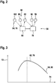
- FIG. 3 illustrates determining the calibration value 62.
- FIG. 3 shows the relationship between the ionization flow 66 and a fuel-air ratio at a constant fan speed 54.
- the fuel-air ratio is also called lambda value and describes the ratio of an amount of air to a fuel amount in a burner 28 supplied fuel-air mixture.
- the blower speed 54 is a characteristic value determined by the control unit 18, which determines a blower control signal.
- the blower control signal is sent from the control unit 18 to the blower 32 and determines a speed of the area 32.
- the blower speed 54 is a burner power parameter 70.
- a burner power parameter 70 is a measure of power of the heating system 46.
- On a first ordinate axis 72 is the ionization flow 66 applied.
- abscissa 74 the fuel-air ratio is shown.
- the course of the ionization stream 66 has a combustion characteristic maximum 76 at a fuel / air ratio of 1.
- a "maximum combustion parameter" 76 is to be understood as meaning a maximum possible value of the combustion parameter 64 with a constant burner performance parameter 70 in at least certain operating states of the heating system.
- the combustion parameter maximum 76 can be unambiguously assigned to a well-determined value of the fuel-air ratio.
- a combustion parameter maximum 76 is a maximum possible value of the combustion parameter 64 at a constant burner performance parameter 70.
- the heating system 46 is operated with an excess of air, ie with a fuel-air ratio greater than 1, preferably with a fuel-air ratio between 1.2 and 1.4, particularly preferably with a fuel-air ratio of 1.3.
- the combustion characteristics maximum 76 is determined by performing a fluid delivery change.
- the fluid supply change is a short-term, pulse-shaped change of an opening width of the fuel valve 44.
- the heating system 46 is operated with a substantially constant or slowly changing opening width of the fuel valve 44.
- the opening width is increased as quickly as possible starting from a Regelö Maschinensweite to a pulse width and after a pulse duration as quickly as possible lowered to the Regelö Samuelsweite.
- the pulse duration is short compared with other, in normal operation usual variations of the opening width.
- Due to the change in the fluid supply the fuel-air mixture is briefly enriched, that is to say a proportion of fuel is increased. The fuel-air ratio is lowered for a short time.
- a strength of the fluid supply change or the pulse width is selected so that the fuel-air ratio briefly reduced to a value less than 1 becomes.
- pulse opening times required therefor are stored in a characteristic field in the control unit 18, which depends on the burner output parameter 70 and the desired fuel / air ratio in normal operation.
- the ionization current 66 briefly increases to the combustion characteristic maximum 76.
- the combustion parameter maximum 76 is determined in the exemplary embodiment by determining the maximum ionization current 66 in a first time point beginning with the fluid supply change and a second time ending test time interval.
- the control unit 18 evaluates a stored time profile of the ionization current 66. A longer of the test time interval is set by the control unit 18. The length of the test time interval depends on the burner performance parameter 70. In this way, in particular a running time of the fuel-air mixture from the fuel valve 44 to the burner 28 or up to the ionization probe 42 is taken into account.
- the combustion parameter maximum 76 is the calibration value 62.
- the heating system 46 is regulated as necessary as a function of the calibration value 62.
- a nominal combustion parameter is determined as a function of the calibration value 62.
- the nominal combustion parameter is equal to the calibration value 62 multiplied by 0.7.
- the target combustion parameter is an operating parameter which is used in the regulation of the heating system as the setpoint for a combustion parameter 64 in order to achieve the intended or desired fuel / air ratio.
- the heating system 46 is operated in such a way that the ionization flow 66 largely assumes the value of the nominal combustion characteristic during normal operation.
- the opening width or the control opening width of the fuel valve 44 is adjusted by a control process performed by the control unit 18 so that the ionization current 66 largely assumes the value of the target combustion characteristic.
- the nominal combustion parameter is stored in a desired combustion characteristic curve in the control unit 18.
- the desired combustion characteristic curve assigns the required combustion parameter to the burner performance parameter 70 and the desired fuel / air ratio. If necessary, the setpoint combustion characteristic curve is at least partially updated by means of the calibration value 62 or the setpoint combustion parameter determined from the calibration value 62.
- the inspection time 58 is determined.
- the control unit 18 checks whether the calibration value 62 falls below a quality threshold 80.
- the quality threshold 80 is a lower limit for the calibration value 62 stored in the control unit 18. If the calibration value 62 falls below the quality threshold 80, the inspection time 58 is ascertained, in which an inspection time interval is added to a currently present date. In the exemplary embodiment, the inspection time interval is two weeks.
- an inspection message is displayed in which an operator of the heating system 46 is advised to initiate an inspection until the inspection time 58.
- the inspection time interval has any other value. It is conceivable that the inspection time interval depends on operating parameters, in particular on a distance of the calibration value 62 from the quality threshold 80. It is also conceivable that the inspection time 58 largely corresponds to a point in time, at which the calibration value 62 exceeds the quality threshold 80. For example, an inspection message may be displayed and / or transmitted by notifying the operator of the heating system 46 to initiate an inspection as soon as possible.
- FIG. 4 shows a time evolution of the calibration value 62.
- the calibration value 62 is plotted on a second ordinate axis 81.
- An operating time of the heating system is shown on a second axis of abscissa 82.
- results for the calibration value 62 from many iterations of the method 56 are shown.
- a timescale of an in FIG. 4 The measured value of the calibration value 62 is approximately 3000 operating hours.
- the course of the calibration value 62 has a noise. The trend is that the calibration value 62 slowly decreases on average.
- a first calibration value 84 is 79 ⁇ A.
- a second calibration value 86 is 72 ⁇ A.
- a reason for the decrease of the calibration value 62 (see FIG. 4 ) a slowly forming oxidation layer on the Ionisationssonde 42.
- the oxidation layer has an insulating effect.
- FIG. 5 shows a dependence of the calibration value 62 of an ohmic resistance of the oxidation layer.
- the calibration value 62 is shown on a third ordinate axis 88.
- a third axis of abscissa 90 shows the ohmic resistance.
- different measurements of the calibration value 62 are shown with different ohmic resistances.
- a first determination 92 has a calibration value 62 of 75 ⁇ A with a ohmic resistance of 0 k ⁇ .
- the ionization probe 42 has no oxidation layer in the first determination 92.
- a second determination 94 has a calibration value 62 of 62 ⁇ A with an oxidation layer with an ohmic resistance of 450 k ⁇ .
- a strength or a signal strength of the detected combustion parameter 64 is lowered.
- the ionization stream 66 sinks through a growing oxidation layer.
- a measure of the time-limited signal strength of the combustion parameter 64 is the decreasing calibration value 62 over time.
- a limited combustion parameter 64 at least partially restricts functionality of the heating system 46. For example, ionization current 66 is less pronounced than signal noise. Too low a calibration value 62 makes a determination of the target combustion characteristic more inaccurate. In this way, the desired fuel-air ratio can not be adjusted with a desired precision. If the signal of the combustion parameter 64 is reduced too much, an intended and / or correct operation of the heating system 46 may be impossible, in particular with regard to emissions of the heating system 46.
- the quality threshold 80 is selected such that the heating system 46 is underrun for a first time the quality threshold 80 can be operated as intended by the calibration value 62 at least within the inspection time interval or at least until the inspection time 58, or can fully meet intended requirements, in particular with regard to operational safety and emissions.
- the quality threshold 80 in the exemplary embodiment is a value determined in laboratory tests.
- the inspection time interval depends on a deviation of the calibration value 62 from the quality threshold 80.
- the deviation may be a relative or absolute difference of the calibration value 62 from the quality threshold 80.
- the deviation may be the value of the quality threshold 80 less the calibration value 62.
- the calibration value 62 is assigned the inspection time 58 with an inspection function.
- the inspection function assigns the calibration value 62 an inspection time 58 or an inspection time interval.
- the inspection function can also depend on further operating parameters, for example on an operating time or on a burner performance parameter 70.
- the inspection function can be a table or a characteristic map which assigns an inspection time 58 or an inspection time interval to the calibration value 62 at least at intervals.
- the inspection function can also be an analytical, in particular rational function.
- the inspection function or function parameters defining it can be determined in particular in a laboratory test. It is conceivable that the inspection function is based on a self-learning or intelligent algorithm, for example on an artificial neural network.
- a provided calibration value 96 is considered in step 78 (see FIG. 6 ).
- the provided calibration value 96 may be a value provided, in particular, in the memory 12 of the control unit 18.
- the provided calibration value 96 can also be a value which can be determined by a measurement of the combustion parameter 64.
- the provided calibration value 96 can be determined using a different method than the calibration value 62. In this way, the provided calibration value 96 can verify the calibration value 62.
- the provided calibration value 96 is determined from an alternative combustion parameter.
- the calibration value 62 is determined from an operating parameter of the heating system, for example a burner output parameter 70.
- a resulting calibration value is determined from the calibration value 62 and the at least one provided calibration value 96.
- the resulting calibration value may be an average of the calibration value 62 and the at least one provided calibration value 96, in particular variants with a weighting.
- the resulting calibration value is used instead of the calibration value 62 as in the above-described variants of the method 56 for determining the inspection time 58. For example, it can be checked whether the resulting calibration value falls below the quality threshold 80. It is also conceivable that the inspection time 58 or the inspection time interval is determined with an inspection function. The inspection function assigns an inspection time 58 or an inspection time interval to the resulting calibration value.
- the inspection time 58 or the inspection time interval is determined with an extended inspection function.
- the extended inspection function assigns an inspection time 58 or an inspection time interval to the calibration value 62 and the at least one provided calibration value 96.
- the inspection function may also depend on other operating parameters, such as an operating time or a Burner performance parameter 70.
- the inspection function may be a table or a characteristic map which assigns an inspection time 58 or an inspection time interval to the calibration value 62 and the at least one provided calibration value 96 at least at intervals.
- the inspection function can also be an analytical, in particular rational function.
- the inspection function or function parameters defining it can be determined in particular in a laboratory test. It is conceivable that the inspection function is based on a self-learning or intelligent algorithm, for example on an artificial neural network.
- FIG. 6 Figure 4 shows a current iteration 98 of the method 56 and a previous iteration 100 of an alternative embodiment.
- the calibration value 62 from the previous iteration 100 is stored in the memory 12.
- the calibration value 62 stored in memory from the previous iteration 100 is used as the provided calibration value 96.
- further provided calibration values 96 are used, which are determined in earlier preceding iterations 100. In this way, the temporal evolution of the calibration value 62 can be taken into account.
- a resulting calibration value can be determined, in particular in which the provided calibration values 96 are each weighted the weaker the further a time point of their respective determination is.
- the provided calibration values 96 can be statistically evaluated. For example, statistical leaks can be taken into account in this way.
- the calibration value 62 is determined at a constant fan speed 54 with the value of a test power 102 (see FIG. 2 ).
- the test performance 102 is a constant value stored in the control unit 18.
- the heating system 46 regularly performs calibrations in which a calibration value 62 is determined.
- the method 56 is carried out if the currently present fan speed 54 largely corresponds to the test power 102.
- the test power 102 is selected so that the fan speed 54 often assumes the value of the test power 102 in the normal operation of the heating system 46.
- the test performance 102 is determined in a test phase after installation of the heating system 46.
- the heating system 46 In the test phase, a typical operation of the heating system 46 is examined, in particular how long the heating system 46 is operated at which fan speed 54. As test performance 102, a value of the fan speed 54 is selected with which the heating system 46 was operated long enough in the test phase. In variants of the exemplary embodiment, the calibration value 62 is determined at a burner output parameter 70 which has the value of the test output 102. In further variants, the heating system 46 is repeated, preferably operated regularly in a calibration mode in which the heating system 46 is operated at the test performance 102 and the calibration value 62 is determined.
- the calibration value 62 is determined at at least two different combustion characteristics 64.
- the calibration value 62 can be determined for substantially all combustion parameters 64.
- the currently existing combustion parameter 64 or a combustion parameter 64 present when determining the calibration value 62 is detected and taken into account in the determination of the inspection time 58 in step 78.
- the Quality threshold 80 depend on the fan speed 54. It is conceivable that the inspection function and / or the extended inspection function depend on the burner performance parameter 70.
- the heating system 46 is regulated as a function of the calibration value 62.
- the heating system 46 is calibrated in dependence on the calibration value 62, if necessary. If the calibration value 62 deviates too much from the quality threshold 80, the heating system 46 is calibrated.
- the normal operation of the heating system 46 is interrupted and the heating system 46 passes through a substantially complete power range.
- the heating system 46 is operated with different values of the burner output parameter 70, which are arranged substantially uniformly between a minimum burner output parameter and a maximum burner output parameter.
- the calibration value 62 is determined and stored in the control unit 18. With the aid of the calibration value 62 for different burner power parameters 70 determined in this way, the desired combustion characteristic curve stored in the control unit 18 is largely completely updated.
- the calibration value 62 is a combustion parameter maximum 76.
- the combustion parameter 64 is an ionization current 66.
- the ionization current 66 is known to have a combustion parameter maximum 76 at a value of 1 for a fuel / air ratio. Therefore, the combustion parameter maximum 76 is a suitable calibration value 62.
- the calibration value 62 is a combustion averaged parameter 64 over time.
- the calibration value 62 is a value of Combustion parameter 64, which is largely constant over sufficiently large, preferably contiguous time periods.
- the combustion parameter 64 is an ionization stream 66.
- the ionization stream 66 is determined by an ionization current measurement on a flame 40 of the heating system 46.
- the ionization current 66 is determined by the ionization probe 42 and transmitted to the control unit 18.
- the combustion parameter 64 is a light intensity, a lambda value, a pollutant emission and / or a temperature.
- the light intensity at the flame 40 is determined by a photodiode.
- the lambda value is measured with a lambda probe in an exhaust gas.
- the exhaust system 38 has the lambda probe.
- the pollutant emission is determined by a sensor device, which is located on the flame 40 and / or in the exhaust system 38.
- the temperature is determined by a contact thermometer and / or a non-contact thermometer, in particular a pyrometer. The thermometer may be located in the exhaust system 38 and / or the flame 40 measured.
Landscapes
- Engineering & Computer Science (AREA)
- Chemical & Material Sciences (AREA)
- Combustion & Propulsion (AREA)
- Mechanical Engineering (AREA)
- General Engineering & Computer Science (AREA)
- Regulation And Control Of Combustion (AREA)
Applications Claiming Priority (4)
| Application Number | Priority Date | Filing Date | Title |
|---|---|---|---|
| DE102016216630 | 2016-09-02 | ||
| DE102016216625 | 2016-09-02 | ||
| DE102016216613 | 2016-09-02 | ||
| DE102017204017.3A DE102017204017A1 (de) | 2016-09-02 | 2017-03-10 | Verfahren zum Festlegen eines Inspektionszeitpunktes in einem Heizsystem sowie eine Steuereinheit und ein Heizsystem |
Publications (2)
| Publication Number | Publication Date |
|---|---|
| EP3290802A1 true EP3290802A1 (fr) | 2018-03-07 |
| EP3290802B1 EP3290802B1 (fr) | 2022-01-19 |
Family
ID=59699593
Family Applications (1)
| Application Number | Title | Priority Date | Filing Date |
|---|---|---|---|
| EP17187719.4A Active EP3290802B1 (fr) | 2016-09-02 | 2017-08-24 | Procédé de détermination d'une date d'inspection dans un système de chauffage ainsi qu'unité de commande et système de chauffage |
Country Status (2)
| Country | Link |
|---|---|
| EP (1) | EP3290802B1 (fr) |
| ES (1) | ES2910172T3 (fr) |
Cited By (1)
| Publication number | Priority date | Publication date | Assignee | Title |
|---|---|---|---|---|
| DE102019131577A1 (de) * | 2019-11-22 | 2021-05-27 | Vaillant Gmbh | Verfahren und Vorrichtung zur Messung des Lambda-Wertes in einem fossil befeuerten Brenner, insbesondere für eine Heizungs- und/oder Brauchwasseranlage |
Citations (4)
| Publication number | Priority date | Publication date | Assignee | Title |
|---|---|---|---|---|
| EP0770824A2 (fr) * | 1995-10-25 | 1997-05-02 | STIEBEL ELTRON GmbH & Co. KG | Procédé et circuit pour commander un brûleur à gaz |
| DE10003819C1 (de) * | 2000-01-28 | 2001-05-17 | Honeywell Bv | Verfahren zum Betreiben eines Gasbrenners |
| DE10111077A1 (de) * | 2001-03-08 | 2002-09-26 | Bosch Gmbh Robert | Gasverbrennungsgerät, insbesondere Gasheizgerät |
| DE102013214610A1 (de) * | 2013-07-26 | 2015-01-29 | E.On New Build & Technology Gmbh | Verfahren und Vorrichtung zur Bestimmung von Kennwerten von Brenngasen |
Family Cites Families (3)
| Publication number | Priority date | Publication date | Assignee | Title |
|---|---|---|---|---|
| AT505244B1 (de) * | 2007-06-11 | 2009-08-15 | Vaillant Austria Gmbh | Verfahren zur überprüfung des ionisationselektrodensignals bei brennern |
| DE102011079325B4 (de) * | 2011-07-18 | 2017-01-26 | Viessmann Werke Gmbh & Co Kg | Verfahren zur Luftzahlregelung eines Brenners |
| DE102013014379A1 (de) * | 2013-08-30 | 2015-03-05 | Kübler Gmbh | Verfahren zur Bestimmung des Wartungszustands einer Heizungsanlage |
-
2017
- 2017-08-24 EP EP17187719.4A patent/EP3290802B1/fr active Active
- 2017-08-24 ES ES17187719T patent/ES2910172T3/es active Active
Patent Citations (4)
| Publication number | Priority date | Publication date | Assignee | Title |
|---|---|---|---|---|
| EP0770824A2 (fr) * | 1995-10-25 | 1997-05-02 | STIEBEL ELTRON GmbH & Co. KG | Procédé et circuit pour commander un brûleur à gaz |
| DE10003819C1 (de) * | 2000-01-28 | 2001-05-17 | Honeywell Bv | Verfahren zum Betreiben eines Gasbrenners |
| DE10111077A1 (de) * | 2001-03-08 | 2002-09-26 | Bosch Gmbh Robert | Gasverbrennungsgerät, insbesondere Gasheizgerät |
| DE102013214610A1 (de) * | 2013-07-26 | 2015-01-29 | E.On New Build & Technology Gmbh | Verfahren und Vorrichtung zur Bestimmung von Kennwerten von Brenngasen |
Cited By (1)
| Publication number | Priority date | Publication date | Assignee | Title |
|---|---|---|---|---|
| DE102019131577A1 (de) * | 2019-11-22 | 2021-05-27 | Vaillant Gmbh | Verfahren und Vorrichtung zur Messung des Lambda-Wertes in einem fossil befeuerten Brenner, insbesondere für eine Heizungs- und/oder Brauchwasseranlage |
Also Published As
| Publication number | Publication date |
|---|---|
| EP3290802B1 (fr) | 2022-01-19 |
| ES2910172T3 (es) | 2022-05-11 |
Similar Documents
| Publication | Publication Date | Title |
|---|---|---|
| DE102017204017A1 (de) | Verfahren zum Festlegen eines Inspektionszeitpunktes in einem Heizsystem sowie eine Steuereinheit und ein Heizsystem | |
| EP1936290B1 (fr) | Procédé et dispositif destinés à la détection de l'état hydraulique d'une installation de chauffage | |
| EP3290797B1 (fr) | Procédé de détection d'un état de vieillissement d'un système de chauffage ainsi qu'une unité de commande et système de chauffage | |
| EP2093644B1 (fr) | Procédé et dispositif pour modifier une grandeur de température mesurée à l'entrée d'un régulateur de chauffage | |
| EP2622337B1 (fr) | Procédés d'étalonnage, de validation et d'ajustement d'une sonde lambda | |
| DE102017204012A1 (de) | Verfahren zur Kontrolle eines Brennstoff-Luft-Verhältnisses in einem Heizsystem sowie eine Steuereinheit und ein Heizsystem | |
| DE102015210583A1 (de) | Heizgerätevorrichtung und Verfahren zum Betrieb einer Heizgerätevorrichtung | |
| DE102008020651B3 (de) | Ansteuerschaltung für einen elektrochemischen Gassensor und Verfahren zum Einstellen eines elektrochemischen Gassensors | |
| EP3290798B1 (fr) | Procédé de réglage et de commande d'un rapport air-combustible dans un système de chauffage ainsi qu'unité de commande et système de chauffage | |
| EP3290802B1 (fr) | Procédé de détermination d'une date d'inspection dans un système de chauffage ainsi qu'unité de commande et système de chauffage | |
| DE102017204003A1 (de) | Verfahren zur Einstellung und Regelung eines Brennstoff-Luft-Verhältnisses in einem Heizsystem sowie eine Steuereinheit und ein Heizsystem | |
| EP3290796B1 (fr) | Procédé de commande d'un rapport air-combustible dans un système de chauffage et unité de commande et système de chauffage | |
| EP3290800B1 (fr) | Procédé d'actualisation d'une caractéristique dans un système de chauffage ainsi que unité de commande et système de chauffage | |
| EP3290801B1 (fr) | Procédé de commande d'un rapport air-combustible dans un système de chauffage et unité de commande et système de chauffage | |
| EP3152432A1 (fr) | Procédé de correction d'une caractéristique lambda de tension | |
| EP3715716B1 (fr) | Procédé de réglage et de commande d'un rapport air-combustible dans un système de chauffage ainsi qu'unité de commande et système de chauffage | |
| DE102017204014A1 (de) | Verfahren zur Bestimmung einer Brennstofftypengröße in einem Heizsystem | |
| DE102011017015B4 (de) | Verfahren zum Betreiben einer Lambdasonde | |
| EP2322916A2 (fr) | Procédé de traitement d'une résistance ohmique mesurée R(t) d'un élément de mesure doté d'une résistance ohmique dépendant de la température | |
| EP4459183B1 (fr) | Procédé de fonctionnement d'un appareil de chauffage, appareil de chauffage et programme informatique | |
| EP3339735B1 (fr) | Procédé de commande d'un rapport air-combustible dans un système de chauffage, unité de commande et système de chauffage | |
| EP4538594A1 (fr) | Procédé de détermination et/ou d'utilisation de la puissance de fonctionnement d'un dispositif de combustion | |
| DE102016216617A1 (de) | Verfahren zur Einstellung eines neuen Kalibrierzeitpunktes in einem Heizsystem sowie eine Steuereinheit und ein Heizsystem |
Legal Events
| Date | Code | Title | Description |
|---|---|---|---|
| PUAI | Public reference made under article 153(3) epc to a published international application that has entered the european phase |
Free format text: ORIGINAL CODE: 0009012 |
|
| STAA | Information on the status of an ep patent application or granted ep patent |
Free format text: STATUS: THE APPLICATION HAS BEEN PUBLISHED |
|
| AK | Designated contracting states |
Kind code of ref document: A1 Designated state(s): AL AT BE BG CH CY CZ DE DK EE ES FI FR GB GR HR HU IE IS IT LI LT LU LV MC MK MT NL NO PL PT RO RS SE SI SK SM TR |
|
| AX | Request for extension of the european patent |
Extension state: BA ME |
|
| STAA | Information on the status of an ep patent application or granted ep patent |
Free format text: STATUS: REQUEST FOR EXAMINATION WAS MADE |
|
| 17P | Request for examination filed |
Effective date: 20180907 |
|
| RBV | Designated contracting states (corrected) |
Designated state(s): AL AT BE BG CH CY CZ DE DK EE ES FI FR GB GR HR HU IE IS IT LI LT LU LV MC MK MT NL NO PL PT RO RS SE SI SK SM TR |
|
| STAA | Information on the status of an ep patent application or granted ep patent |
Free format text: STATUS: EXAMINATION IS IN PROGRESS |
|
| RAP1 | Party data changed (applicant data changed or rights of an application transferred) |
Owner name: ROBERT BOSCH GMBH |
|
| 17Q | First examination report despatched |
Effective date: 20200415 |
|
| GRAP | Despatch of communication of intention to grant a patent |
Free format text: ORIGINAL CODE: EPIDOSNIGR1 |
|
| STAA | Information on the status of an ep patent application or granted ep patent |
Free format text: STATUS: GRANT OF PATENT IS INTENDED |
|
| INTG | Intention to grant announced |
Effective date: 20210830 |
|
| GRAS | Grant fee paid |
Free format text: ORIGINAL CODE: EPIDOSNIGR3 |
|
| GRAA | (expected) grant |
Free format text: ORIGINAL CODE: 0009210 |
|
| STAA | Information on the status of an ep patent application or granted ep patent |
Free format text: STATUS: THE PATENT HAS BEEN GRANTED |
|
| AK | Designated contracting states |
Kind code of ref document: B1 Designated state(s): AL AT BE BG CH CY CZ DE DK EE ES FI FR GB GR HR HU IE IS IT LI LT LU LV MC MK MT NL NO PL PT RO RS SE SI SK SM TR |
|
| REG | Reference to a national code |
Ref country code: GB Ref legal event code: FG4D Free format text: NOT ENGLISH |
|
| REG | Reference to a national code |
Ref country code: CH Ref legal event code: EP |
|
| REG | Reference to a national code |
Ref country code: DE Ref legal event code: R096 Ref document number: 502017012462 Country of ref document: DE |
|
| REG | Reference to a national code |
Ref country code: AT Ref legal event code: REF Ref document number: 1464005 Country of ref document: AT Kind code of ref document: T Effective date: 20220215 |
|
| REG | Reference to a national code |
Ref country code: IE Ref legal event code: FG4D Free format text: LANGUAGE OF EP DOCUMENT: GERMAN |
|
| REG | Reference to a national code |
Ref country code: NL Ref legal event code: FP |
|
| REG | Reference to a national code |
Ref country code: LT Ref legal event code: MG9D |
|
| REG | Reference to a national code |
Ref country code: ES Ref legal event code: FG2A Ref document number: 2910172 Country of ref document: ES Kind code of ref document: T3 Effective date: 20220511 |
|
| PG25 | Lapsed in a contracting state [announced via postgrant information from national office to epo] |
Ref country code: SE Free format text: LAPSE BECAUSE OF FAILURE TO SUBMIT A TRANSLATION OF THE DESCRIPTION OR TO PAY THE FEE WITHIN THE PRESCRIBED TIME-LIMIT Effective date: 20220119 Ref country code: RS Free format text: LAPSE BECAUSE OF FAILURE TO SUBMIT A TRANSLATION OF THE DESCRIPTION OR TO PAY THE FEE WITHIN THE PRESCRIBED TIME-LIMIT Effective date: 20220119 Ref country code: PT Free format text: LAPSE BECAUSE OF FAILURE TO SUBMIT A TRANSLATION OF THE DESCRIPTION OR TO PAY THE FEE WITHIN THE PRESCRIBED TIME-LIMIT Effective date: 20220519 Ref country code: NO Free format text: LAPSE BECAUSE OF FAILURE TO SUBMIT A TRANSLATION OF THE DESCRIPTION OR TO PAY THE FEE WITHIN THE PRESCRIBED TIME-LIMIT Effective date: 20220419 Ref country code: LT Free format text: LAPSE BECAUSE OF FAILURE TO SUBMIT A TRANSLATION OF THE DESCRIPTION OR TO PAY THE FEE WITHIN THE PRESCRIBED TIME-LIMIT Effective date: 20220119 Ref country code: HR Free format text: LAPSE BECAUSE OF FAILURE TO SUBMIT A TRANSLATION OF THE DESCRIPTION OR TO PAY THE FEE WITHIN THE PRESCRIBED TIME-LIMIT Effective date: 20220119 Ref country code: BG Free format text: LAPSE BECAUSE OF FAILURE TO SUBMIT A TRANSLATION OF THE DESCRIPTION OR TO PAY THE FEE WITHIN THE PRESCRIBED TIME-LIMIT Effective date: 20220419 |
|
| PG25 | Lapsed in a contracting state [announced via postgrant information from national office to epo] |
Ref country code: PL Free format text: LAPSE BECAUSE OF FAILURE TO SUBMIT A TRANSLATION OF THE DESCRIPTION OR TO PAY THE FEE WITHIN THE PRESCRIBED TIME-LIMIT Effective date: 20220119 Ref country code: LV Free format text: LAPSE BECAUSE OF FAILURE TO SUBMIT A TRANSLATION OF THE DESCRIPTION OR TO PAY THE FEE WITHIN THE PRESCRIBED TIME-LIMIT Effective date: 20220119 Ref country code: GR Free format text: LAPSE BECAUSE OF FAILURE TO SUBMIT A TRANSLATION OF THE DESCRIPTION OR TO PAY THE FEE WITHIN THE PRESCRIBED TIME-LIMIT Effective date: 20220420 Ref country code: FI Free format text: LAPSE BECAUSE OF FAILURE TO SUBMIT A TRANSLATION OF THE DESCRIPTION OR TO PAY THE FEE WITHIN THE PRESCRIBED TIME-LIMIT Effective date: 20220119 |
|
| PG25 | Lapsed in a contracting state [announced via postgrant information from national office to epo] |
Ref country code: IS Free format text: LAPSE BECAUSE OF FAILURE TO SUBMIT A TRANSLATION OF THE DESCRIPTION OR TO PAY THE FEE WITHIN THE PRESCRIBED TIME-LIMIT Effective date: 20220519 |
|
| REG | Reference to a national code |
Ref country code: DE Ref legal event code: R097 Ref document number: 502017012462 Country of ref document: DE |
|
| PG25 | Lapsed in a contracting state [announced via postgrant information from national office to epo] |
Ref country code: SM Free format text: LAPSE BECAUSE OF FAILURE TO SUBMIT A TRANSLATION OF THE DESCRIPTION OR TO PAY THE FEE WITHIN THE PRESCRIBED TIME-LIMIT Effective date: 20220119 Ref country code: SK Free format text: LAPSE BECAUSE OF FAILURE TO SUBMIT A TRANSLATION OF THE DESCRIPTION OR TO PAY THE FEE WITHIN THE PRESCRIBED TIME-LIMIT Effective date: 20220119 Ref country code: RO Free format text: LAPSE BECAUSE OF FAILURE TO SUBMIT A TRANSLATION OF THE DESCRIPTION OR TO PAY THE FEE WITHIN THE PRESCRIBED TIME-LIMIT Effective date: 20220119 Ref country code: EE Free format text: LAPSE BECAUSE OF FAILURE TO SUBMIT A TRANSLATION OF THE DESCRIPTION OR TO PAY THE FEE WITHIN THE PRESCRIBED TIME-LIMIT Effective date: 20220119 Ref country code: DK Free format text: LAPSE BECAUSE OF FAILURE TO SUBMIT A TRANSLATION OF THE DESCRIPTION OR TO PAY THE FEE WITHIN THE PRESCRIBED TIME-LIMIT Effective date: 20220119 Ref country code: CZ Free format text: LAPSE BECAUSE OF FAILURE TO SUBMIT A TRANSLATION OF THE DESCRIPTION OR TO PAY THE FEE WITHIN THE PRESCRIBED TIME-LIMIT Effective date: 20220119 |
|
| PLBE | No opposition filed within time limit |
Free format text: ORIGINAL CODE: 0009261 |
|
| STAA | Information on the status of an ep patent application or granted ep patent |
Free format text: STATUS: NO OPPOSITION FILED WITHIN TIME LIMIT |
|
| PG25 | Lapsed in a contracting state [announced via postgrant information from national office to epo] |
Ref country code: AL Free format text: LAPSE BECAUSE OF FAILURE TO SUBMIT A TRANSLATION OF THE DESCRIPTION OR TO PAY THE FEE WITHIN THE PRESCRIBED TIME-LIMIT Effective date: 20220119 |
|
| 26N | No opposition filed |
Effective date: 20221020 |
|
| PG25 | Lapsed in a contracting state [announced via postgrant information from national office to epo] |
Ref country code: SI Free format text: LAPSE BECAUSE OF FAILURE TO SUBMIT A TRANSLATION OF THE DESCRIPTION OR TO PAY THE FEE WITHIN THE PRESCRIBED TIME-LIMIT Effective date: 20220119 |
|
| PG25 | Lapsed in a contracting state [announced via postgrant information from national office to epo] |
Ref country code: MC Free format text: LAPSE BECAUSE OF FAILURE TO SUBMIT A TRANSLATION OF THE DESCRIPTION OR TO PAY THE FEE WITHIN THE PRESCRIBED TIME-LIMIT Effective date: 20220119 |
|
| REG | Reference to a national code |
Ref country code: CH Ref legal event code: PL |
|
| GBPC | Gb: european patent ceased through non-payment of renewal fee |
Effective date: 20220824 |
|
| PG25 | Lapsed in a contracting state [announced via postgrant information from national office to epo] |
Ref country code: LU Free format text: LAPSE BECAUSE OF NON-PAYMENT OF DUE FEES Effective date: 20220824 Ref country code: LI Free format text: LAPSE BECAUSE OF NON-PAYMENT OF DUE FEES Effective date: 20220831 Ref country code: CH Free format text: LAPSE BECAUSE OF NON-PAYMENT OF DUE FEES Effective date: 20220831 |
|
| PG25 | Lapsed in a contracting state [announced via postgrant information from national office to epo] |
Ref country code: IT Free format text: LAPSE BECAUSE OF FAILURE TO SUBMIT A TRANSLATION OF THE DESCRIPTION OR TO PAY THE FEE WITHIN THE PRESCRIBED TIME-LIMIT Effective date: 20220119 Ref country code: IE Free format text: LAPSE BECAUSE OF NON-PAYMENT OF DUE FEES Effective date: 20220824 |
|
| REG | Reference to a national code |
Ref country code: AT Ref legal event code: MM01 Ref document number: 1464005 Country of ref document: AT Kind code of ref document: T Effective date: 20220824 |
|
| PG25 | Lapsed in a contracting state [announced via postgrant information from national office to epo] |
Ref country code: GB Free format text: LAPSE BECAUSE OF NON-PAYMENT OF DUE FEES Effective date: 20220824 Ref country code: AT Free format text: LAPSE BECAUSE OF NON-PAYMENT OF DUE FEES Effective date: 20220824 |
|
| PG25 | Lapsed in a contracting state [announced via postgrant information from national office to epo] |
Ref country code: HU Free format text: LAPSE BECAUSE OF FAILURE TO SUBMIT A TRANSLATION OF THE DESCRIPTION OR TO PAY THE FEE WITHIN THE PRESCRIBED TIME-LIMIT; INVALID AB INITIO Effective date: 20170824 |
|
| PG25 | Lapsed in a contracting state [announced via postgrant information from national office to epo] |
Ref country code: CY Free format text: LAPSE BECAUSE OF FAILURE TO SUBMIT A TRANSLATION OF THE DESCRIPTION OR TO PAY THE FEE WITHIN THE PRESCRIBED TIME-LIMIT Effective date: 20220119 |
|
| PG25 | Lapsed in a contracting state [announced via postgrant information from national office to epo] |
Ref country code: MK Free format text: LAPSE BECAUSE OF FAILURE TO SUBMIT A TRANSLATION OF THE DESCRIPTION OR TO PAY THE FEE WITHIN THE PRESCRIBED TIME-LIMIT Effective date: 20220119 |
|
| PG25 | Lapsed in a contracting state [announced via postgrant information from national office to epo] |
Ref country code: MT Free format text: LAPSE BECAUSE OF FAILURE TO SUBMIT A TRANSLATION OF THE DESCRIPTION OR TO PAY THE FEE WITHIN THE PRESCRIBED TIME-LIMIT Effective date: 20220119 |
|
| PGFP | Annual fee paid to national office [announced via postgrant information from national office to epo] |
Ref country code: NL Payment date: 20250821 Year of fee payment: 9 |
|
| PGFP | Annual fee paid to national office [announced via postgrant information from national office to epo] |
Ref country code: ES Payment date: 20250917 Year of fee payment: 9 |
|
| PGFP | Annual fee paid to national office [announced via postgrant information from national office to epo] |
Ref country code: BE Payment date: 20250820 Year of fee payment: 9 |
|
| PGFP | Annual fee paid to national office [announced via postgrant information from national office to epo] |
Ref country code: FR Payment date: 20250821 Year of fee payment: 9 |
|
| PG25 | Lapsed in a contracting state [announced via postgrant information from national office to epo] |
Ref country code: TR Free format text: LAPSE BECAUSE OF FAILURE TO SUBMIT A TRANSLATION OF THE DESCRIPTION OR TO PAY THE FEE WITHIN THE PRESCRIBED TIME-LIMIT Effective date: 20220119 |
|
| PGFP | Annual fee paid to national office [announced via postgrant information from national office to epo] |
Ref country code: DE Payment date: 20251021 Year of fee payment: 9 |