EP3290805B1 - Ensemble de buse de combustible comportant un résonateur - Google Patents
Ensemble de buse de combustible comportant un résonateur Download PDFInfo
- Publication number
- EP3290805B1 EP3290805B1 EP17189350.6A EP17189350A EP3290805B1 EP 3290805 B1 EP3290805 B1 EP 3290805B1 EP 17189350 A EP17189350 A EP 17189350A EP 3290805 B1 EP3290805 B1 EP 3290805B1
- Authority
- EP
- European Patent Office
- Prior art keywords
- resonator
- sidewall
- mixing tubes
- mixing
- tubes
- Prior art date
- Legal status (The legal status is an assumption and is not a legal conclusion. Google has not performed a legal analysis and makes no representation as to the accuracy of the status listed.)
- Not-in-force
Links
- 239000000446 fuel Substances 0.000 title claims description 110
- 238000002156 mixing Methods 0.000 claims description 123
- 239000012530 fluid Substances 0.000 claims description 27
- 238000004891 communication Methods 0.000 claims description 18
- 238000011144 upstream manufacturing Methods 0.000 claims description 14
- 238000002485 combustion reaction Methods 0.000 description 19
- 239000007789 gas Substances 0.000 description 13
- 239000000567 combustion gas Substances 0.000 description 6
- 238000000429 assembly Methods 0.000 description 3
- 230000000712 assembly Effects 0.000 description 3
- 239000000203 mixture Substances 0.000 description 3
- 230000010355 oscillation Effects 0.000 description 3
- 238000005219 brazing Methods 0.000 description 2
- 238000001816 cooling Methods 0.000 description 2
- 238000010586 diagram Methods 0.000 description 2
- 238000005516 engineering process Methods 0.000 description 2
- 238000012986 modification Methods 0.000 description 2
- 230000004048 modification Effects 0.000 description 2
- 238000003466 welding Methods 0.000 description 2
- 239000000654 additive Substances 0.000 description 1
- 230000000996 additive effect Effects 0.000 description 1
- 239000012809 cooling fluid Substances 0.000 description 1
- 230000005611 electricity Effects 0.000 description 1
- 238000004519 manufacturing process Methods 0.000 description 1
- 238000000034 method Methods 0.000 description 1
- 230000037361 pathway Effects 0.000 description 1
Images






Classifications
-
- F—MECHANICAL ENGINEERING; LIGHTING; HEATING; WEAPONS; BLASTING
- F23—COMBUSTION APPARATUS; COMBUSTION PROCESSES
- F23R—GENERATING COMBUSTION PRODUCTS OF HIGH PRESSURE OR HIGH VELOCITY, e.g. GAS-TURBINE COMBUSTION CHAMBERS
- F23R3/00—Continuous combustion chambers using liquid or gaseous fuel
- F23R3/28—Continuous combustion chambers using liquid or gaseous fuel characterised by the fuel supply
- F23R3/286—Continuous combustion chambers using liquid or gaseous fuel characterised by the fuel supply having fuel-air premixing devices
-
- F—MECHANICAL ENGINEERING; LIGHTING; HEATING; WEAPONS; BLASTING
- F02—COMBUSTION ENGINES; HOT-GAS OR COMBUSTION-PRODUCT ENGINE PLANTS
- F02C—GAS-TURBINE PLANTS; AIR INTAKES FOR JET-PROPULSION PLANTS; CONTROLLING FUEL SUPPLY IN AIR-BREATHING JET-PROPULSION PLANTS
- F02C3/00—Gas-turbine plants characterised by the use of combustion products as the working fluid
- F02C3/04—Gas-turbine plants characterised by the use of combustion products as the working fluid having a turbine driving a compressor
-
- F—MECHANICAL ENGINEERING; LIGHTING; HEATING; WEAPONS; BLASTING
- F02—COMBUSTION ENGINES; HOT-GAS OR COMBUSTION-PRODUCT ENGINE PLANTS
- F02C—GAS-TURBINE PLANTS; AIR INTAKES FOR JET-PROPULSION PLANTS; CONTROLLING FUEL SUPPLY IN AIR-BREATHING JET-PROPULSION PLANTS
- F02C7/00—Features, components parts, details or accessories, not provided for in, or of interest apart form groups F02C1/00 - F02C6/00; Air intakes for jet-propulsion plants
- F02C7/22—Fuel supply systems
- F02C7/222—Fuel flow conduits, e.g. manifolds
-
- F—MECHANICAL ENGINEERING; LIGHTING; HEATING; WEAPONS; BLASTING
- F23—COMBUSTION APPARATUS; COMBUSTION PROCESSES
- F23R—GENERATING COMBUSTION PRODUCTS OF HIGH PRESSURE OR HIGH VELOCITY, e.g. GAS-TURBINE COMBUSTION CHAMBERS
- F23R3/00—Continuous combustion chambers using liquid or gaseous fuel
- F23R3/02—Continuous combustion chambers using liquid or gaseous fuel characterised by the air-flow or gas-flow configuration
- F23R3/04—Air inlet arrangements
-
- F—MECHANICAL ENGINEERING; LIGHTING; HEATING; WEAPONS; BLASTING
- F05—INDEXING SCHEMES RELATING TO ENGINES OR PUMPS IN VARIOUS SUBCLASSES OF CLASSES F01-F04
- F05D—INDEXING SCHEME FOR ASPECTS RELATING TO NON-POSITIVE-DISPLACEMENT MACHINES OR ENGINES, GAS-TURBINES OR JET-PROPULSION PLANTS
- F05D2220/00—Application
- F05D2220/30—Application in turbines
- F05D2220/32—Application in turbines in gas turbines
-
- F—MECHANICAL ENGINEERING; LIGHTING; HEATING; WEAPONS; BLASTING
- F05—INDEXING SCHEMES RELATING TO ENGINES OR PUMPS IN VARIOUS SUBCLASSES OF CLASSES F01-F04
- F05D—INDEXING SCHEME FOR ASPECTS RELATING TO NON-POSITIVE-DISPLACEMENT MACHINES OR ENGINES, GAS-TURBINES OR JET-PROPULSION PLANTS
- F05D2240/00—Components
- F05D2240/35—Combustors or associated equipment
-
- F—MECHANICAL ENGINEERING; LIGHTING; HEATING; WEAPONS; BLASTING
- F23—COMBUSTION APPARATUS; COMBUSTION PROCESSES
- F23R—GENERATING COMBUSTION PRODUCTS OF HIGH PRESSURE OR HIGH VELOCITY, e.g. GAS-TURBINE COMBUSTION CHAMBERS
- F23R2900/00—Special features of, or arrangements for continuous combustion chambers; Combustion processes therefor
- F23R2900/00012—Details of sealing devices
-
- F—MECHANICAL ENGINEERING; LIGHTING; HEATING; WEAPONS; BLASTING
- F23—COMBUSTION APPARATUS; COMBUSTION PROCESSES
- F23R—GENERATING COMBUSTION PRODUCTS OF HIGH PRESSURE OR HIGH VELOCITY, e.g. GAS-TURBINE COMBUSTION CHAMBERS
- F23R2900/00—Special features of, or arrangements for continuous combustion chambers; Combustion processes therefor
- F23R2900/00014—Reducing thermo-acoustic vibrations by passive means, e.g. by Helmholtz resonators
Definitions
- the present invention generally involves a bundled tube type fuel nozzle assembly for a gas turbine combustor. More specifically, the invention relates to a bundled tube type fuel nozzle assembly with a high frequency dynamics resonator incorporated therein.
- the combustor includes an upstream surface that extends radially across at least a portion of the combustor, a downstream surface that extends radially across at least a portion of the combustor and is axially separated from the upstream surface, and a plurality of tubes that extend through the downstream surface.
- a resonator is upstream from at least one of the tubes, and a fluid passage extends through the resonator and into the least one tube.
- a bundled tube type fuel nozzle assembly generally includes multiple tubes that extend through a fuel plenum body which is at least partially defined by a forward plate, an aft plate and an outer sleeve. Compressed air flows into an inlet portion of each tube. Fuel from the fuel plenum is injected into each tube where it premixes with the compressed air before it is routed into the combustion zone.
- each tube may be rigidly connected to the aft plate while a downstream end or tip portion is unconstrained, i.e., each tube is cantilevered from the aft plate.
- the downstream end or tip portion of each tube extends through a corresponding tube opening defined in a cap plate which is axially spaced from the aft plate of the fuel plenum body and positioned proximate to the combustion chamber.
- a circumferentially continuous radial gap is defined between an outer surface of each tube at its tip portion and the corresponding tube opening in the cap plate to allow for a cooling fluid, such as compressed air, to flow around the tube towards the combustion chamber, thereby cooling the tip portion.
- combustion dynamics may cause oscillation of the various components resulting in undesirable impacts between the components and increased wear thereof, e.g., the tip portion of each tube may vibrate within the gap potentially resulting in undesirable contact between the individual tubes and the cap plate.
- the fuel nozzle assembly includes a fuel plenum body including a forward plate extending in a radial direction, an aft plate axially spaced from the forward plate and extending in a radial direction, an outer sleeve extending in an axial direction between the forward plate and the aft plate, and a fuel plenum defined by the forward plate, the aft plate and the outer sleeve.
- the fuel nozzle assembly also includes a cap plate axially spaced from the aft plate with an air plenum defined between the aft plate and the cap plate.
- the fuel nozzle assembly further includes a plurality of mixing tubes extending through the fuel plenum body.
- Each of the mixing tubes includes an air inlet, a fuel port in fluid communication with the fuel plenum, and an outlet downstream of the aft plate.
- the fuel nozzle assembly also includes at least one resonator positioned between the aft plate and the cap plate surrounding at least one mixing tube of the plurality of mixing tubes.
- the at least one resonator includes a first sidewall extending in a radial direction, a second sidewall axially spaced from the first sidewall and extending in a radial direction, an outer wall extending in an axial direction between the first sidewall and the second sidewall, such that a resonator chamber is defined by the first sidewall, the second sidewall, and the outer wall.
- At least one inlet into the resonator chamber is in fluid communication with the air plenum.
- the at least one mixing tube surrounded by the at least one resonator comprises an opening in fluid communication with the resonator chamber.
- the combustor includes an end cover coupled to an outer casing and a bundled tube fuel nozzle assembly disposed within the outer casing and coupled to the end cover.
- the fuel nozzle assembly includes a fuel plenum body including a forward plate extending in a radial direction, an aft plate axially spaced from the forward plate and extending in a radial direction, an outer sleeve extending in an axial direction between the forward plate and the aft plate, and a fuel plenum defined by the forward plate, the aft plate and the outer sleeve.
- the fuel nozzle assembly also includes a cap plate axially spaced from the aft plate with an air plenum defined between the aft plate and the cap plate.
- the fuel nozzle assembly further includes a plurality of mixing tubes extending through the fuel plenum body. Each of the mixing tubes includes an air inlet, a fuel port in fluid communication with the fuel plenum, and an outlet downstream of the aft plate.
- the fuel nozzle assembly also includes at least one resonator positioned between the aft plate and the cap plate surrounding at least one mixing tube of the plurality of mixing tubes.
- the at least one resonator includes a first sidewall extending in a radial direction, a second sidewall axially spaced from the first sidewall and extending in a radial direction, an outer wall extending in an axial direction between the first sidewall and the second sidewall, such that a resonator chamber is defined by the first sidewall, the second sidewall, and the outer wall, at least one inlet into the resonator chamber in fluid communication with the air plenum.
- the at least one mixing tube surrounded by the at least one resonator also includes an opening in fluid communication with the resonator chamber.
- a gas turbine including a compressor, a turbine, and a combustor disposed downstream from the compressor and upstream from the turbine.
- the combustor includes an end cover coupled to an outer casing and a bundled tube fuel nozzle assembly disposed within the outer casing and coupled to the end cover.
- the bundled tube fuel nozzle assembly includes a fuel plenum body including a forward plate extending in a radial direction, an aft plate axially spaced from the forward plate and extending in a radial direction, an outer sleeve extending in an axial direction between the forward plate and the aft plate, and a fuel plenum defined by the forward plate, the aft plate and the outer sleeve.
- the fuel nozzle assembly also includes a cap plate axially spaced from the aft plate with an air plenum defined between the aft plate and the cap plate.
- the fuel nozzle assembly further includes a plurality of mixing tubes extending through the fuel plenum body. Each of the mixing tubes includes an air inlet, an outlet downstream of the aft plate, and a fuel port in fluid communication with the fuel plenum.
- the fuel nozzle assembly also includes at least one resonator positioned between the aft plate and the cap plate surrounding at least one mixing tube of the plurality of mixing tubes.
- the at least one resonator includes a first sidewall extending in a radial direction, a second sidewall axially spaced from the first sidewall and extending in a radial direction, an outer wall extending in an axial direction between the first sidewall and the second sidewall, a resonator chamber defined by the first sidewall, the second sidewall, and the outer wall, and at least one inlet into the resonator chamber in fluid communication with the air plenum.
- the at least one mixing tube surrounded by the at least one resonator also includes an opening in fluid communication with the resonator chamber.
- upstream refers to the relative direction with respect to fluid flow in a fluid pathway.
- upstream refers to the direction from which the fluid flows
- downstream refers to the direction to which the fluid flows.
- radially refers to the relative direction that is substantially perpendicular to an axial centerline of a particular component
- axially refers to the relative direction that is substantially parallel and/or coaxially aligned to an axial centerline of a particular component
- circumferentially refers to the relative direction that extends around the axial centerline of a particular component.
- the high frequency dynamics resonator may be tuned to dampen oscillations of a certain frequency or range of frequencies, such as by varying the dimensions of the resonator chambers and/or mixing tube openings.
- more than one resonator may be used, which may all be tuned to the same frequency range, or different resonators may be tuned to dampen different ranges.
- resonators tuned to dampen different frequency ranges may be used to mitigate dynamics from a first fuel nozzle and a second fuel nozzle.
- a bundled tube type fuel nozzle in a first combustor may be provided with a resonator tuned to a first frequency range
- a bundled tube type fuel nozzle in a second combustor may be provided with a resonator tuned to a second frequency range different from the first frequency range.
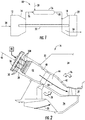
- FIG. 1 illustrates a schematic diagram of an exemplary gas turbine 10.
- the gas turbine 10 generally includes an inlet section 12, a compressor 14 disposed downstream of the inlet section 12, at least one combustor 16 disposed downstream of the compressor 14, a turbine 18 disposed downstream of the combustor 16 and an exhaust section 20 disposed downstream of the turbine 18. Additionally, the gas turbine 10 may include one or more shafts 22 that couple the compressor 14 to the turbine 18.
- air 24 flows through the inlet section 12 and into the compressor 14 where the air 24 is progressively compressed, thus providing compressed air 26 to the combustor 16. At least a portion of the compressed air 26 is mixed with a fuel 28 within the combustor 16 and burned to produce combustion gases 30.
- the combustion gases 30 flow from the combustor 16 into the turbine 18, wherein energy (kinetic and/or thermal) is transferred from the combustion gases 30 to rotor blades (not shown), thus causing shaft 22 to rotate.
- the mechanical rotational energy may then be used for various purposes such as to power the compressor 14 and/or to generate electricity.
- the combustion gases 30 exiting the turbine 18 may then be exhausted from the gas turbine 10 via the exhaust section 20.
- the combustor 16 may be at least partially surrounded by an outer casing 32 such as a compressor discharge casing.
- the outer casing 32 may at least partially define a high pressure plenum 34 that at least partially surrounds various components of the combustor 16.
- the high pressure plenum 34 may be in fluid communication with the compressor 14 ( FIG. 1 ) so as to receive the compressed air 26 therefrom.
- An end cover 36 may be coupled to the outer casing 32.
- the outer casing 32 and the end cover 36 may at least partially define a head end volume or portion 38 of the combustor 16.
- the head end portion 38 is in fluid communication with the high pressure plenum 34 and/or the compressor 14.
- One or more liners or ducts 40 may at least partially define a combustion chamber or zone 42 for combusting the fuel-air mixture and/or may at least partially define a hot gas path 44 through the combustor, for directing the combustion gases 30 towards an inlet to the turbine 18.
- the combustor 16 includes at least one bundled tube type fuel nozzle assembly 100.
- the fuel nozzle assembly 100 is disposed within the outer casing 32 downstream from and/or axially spaced from the end cover 36 with respect to axial centerline 46 of the combustor 16 and upstream from the combustion chamber 42.
- the fuel nozzle assembly 100 is in fluid communication with a gas fuel supply 48 via one or more fluid conduits 50.
- the fluid conduit(s) 50 may be fluidly coupled and/or connected at one end to the end cover 36. It should be understood that the fule nozzle assemblies 100 and/or the fluid conduit(s) may be mounted to structures other than the end cover 36 (e.g., the outer casing 32).
- FIG. 3 provides a cross sectioned side view of a portion of an exemplary fuel nozzle assembly 100 as shown in FIG. 2 , according to at least one embodiment of the present disclosure.
- Various embodiments of the combustor 16 may include different arrangements of the fuel nozzle assembly 100 and is not limited to any particular arrangement unless otherwise specified in the claims.
- the fuel nozzle assembly 100 includes multiple wedge shaped fuel nozzle segments annularly arranged about centerline 46.
- fuel nozzle assembly 100 may further include a circular shaped fuel nozzle segment centered on centerline 46.
- the fuel nozzle assembly 100 may form an annulus or fuel nozzle passage about a center fuel nozzle 50.
- the fuel nozzle assembly 100 and/or each fuel nozzle segment includes a fuel plenum body 102 having a forward or upstream plate 104, an aft plate 106 axially spaced from the forward plate 104 and an outer band or sleeve 108 that extends axially between the forward plate 104 and the aft plate 106.
- a fuel plenum 110 is defined within the fuel plenum body 102.
- the forward plate 104, the aft plate 106 and the outer sleeve 108 may at least partially define the fuel plenum 110.
- fluid conduit 50 may extend through the forward plate 104 to provide fuel to the fuel plenum 110.
- the fuel nozzle assembly 100 includes a cap plate 112 axially spaced from the aft plate 106.
- An air plenum 111 is defined between the aft plate 106 and cap plate 112.
- a hot side 114 of the cap plate 112 is generally disposed adjacent or proximate to the combustion chamber 42.
- the fuel nozzle assembly 100 includes a tube bundle 116 comprising a plurality of tubes 118.
- Each tube 118 extends through the forward plate 104, the fuel plenum 110, the air plenum 111, the aft plate 106 and the cap plate 112.
- the tubes 118 are fixedly connected to and/or form a seal against the aft plate 106.
- the tubes 118 may be welded, brazed or otherwise connected to the aft plate 106.
- Each tube 118 includes an air inlet 120 defined at an upstream end 122 of each respective tube 118 and an outlet 124 defined at a downstream end 126 of each respective tube 118.
- the downstream end portion 126 extends through a corresponding tube opening (not shown) in the cap plate 112, the tube opening being sized to define a circumferentially continuous radial gap between an outer surface of the tube 118 and an inner surface of the corresponding tube opening.
- the circumferentially continuous radial gap permits compressed air 26 to flow around the tube from the air plenum 111 towards the combustion chamber 42, thereby cooling the downstream end portions 126 of the tubes 118.
- Each tube 118 defines a respective premix flow passage 128 through the fuel nozzle assembly 100, for premixing the gaseous fuel 28 ( FIG. 1 ) with the compressed air 26 ( FIG. 1 ) within mixing tube 118 before it is directed into a combustion zone 42 defined downstream from the fuel nozzle.
- one or more tubes 118 of the plurality of tubes 118 is in fluid communication with the fuel plenum 110 via one or more fuel ports 130 defined within the respective tube(s) 118.
- the downstream end portions of tubes 118 are not attached at the cap plate 112, as such, the tube 118 may be described as "cantilevered.”
- combustion dynamics may cause oscillations of the various parts of the combustor 16, which in turn may impact one another.
- the cantilevered tubes 118, particularly the downstream end portion 126 of each tube 118 may move radially with respect to a centerline of each respective tube 118 resulting in contact between the tubes 118 and the corresponding tube openings in the cap plate 112.
- the fuel nozzle assembly 100 may impact a liner or head end 38 of combustor 16.
- Such impacts may cause undesirable wear on the various parts due to the physical force of the impact and/or increased thermal loading on upstream components of combustor 16.
- combustion gases 30 FIG. 1
- the fuel nozzle assembly 100 includes one or more resonators 150 disposed between the aft plate 106 and the cap plate 112.
- the one or more resonators 150 can be axially spaced from the cap plate 112 and upstream of the mixing tube outlet to avoid or minimize exposure of the resonator 150 to heat from combustion zone 42.
- the number of resonators 150 is equal to the number of tubes 118, and there is a one-to-one correspondence between tubes 118 and resonators 150.
- each tube 118 extends through and is surrounded by a single resonator 150 and each resonator 150 has only a single tube extending through it.
- the correspondence between tubes 118 and resonators 150 may vary. In some embodiments, for example as illustrated in FIG. 4 , there may be fewer resonators 150 than tubes 118, and each resonator 150 may have only a single tube 118 extending through it and some tubes 118 may not extend through a resonator 150. Further as illustrated in FIG. 4 , in some embodiments where less than all of the tubes have a corresponding resonator, the subset of tubes 118 not extending through and surrounded by a resonator 150 may include tubes 118 from more than one bundle 116.
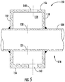
- the resonator 150 includes first and second sidewalls 152 and 154 and an outer wall 156.
- the resonator walls 152, 154, and 156 define a resonator chamber 158.
- a single tube 118 passes through a resonator 150.
- an outer surface 138 of mixing tube 118 can be sealingly fixed to the first sidewall 152 and second sidewall 154, such as by brazing or welding.
- mixing tube 118 and resonator 150 may be formed as a unitary piece, e.g., by additive manufacturing.
- the mixing tube 118 may include one or more openings 132 in fluid communication with the resonator chamber 158.
- the tube opening(s) 132 may be generally offset with respect to the centerline of a pressure inlet 160 of the resonator 150, or in some embodiments the tube openings 132 may be aligned with pressure inlets 160.
- the relative dimensions and location of opening 132 and the volume of the resonator chamber 158 may be specified based at least in part on particular frequencies to be addressed within the combustor 16. For example, although opening 132 is illustrated as normal to the walls of mixing tube 118, openings 132 may also be oblique and/or tapered.
- the shape of sidewalls 152 and 154 may be concave, convex, etc., in order to provide the desired resonator chamber 158 volume, e.g., within a given clearance between adjacent tubes 118.
- Pressure inlet 160 permits pressurized air 26 to enter resonator chamber 158 to provide positive pressure therein relative to the fuel/air mixture within mixing tube 118 so as to avoid or minimize escape of the fuel/air mixture from tube 118 upstream of combustion zone 42.
- the size of pressure inlet 160 is preferably kept to a minimum, e.g., just large enough to pressurize resonator chamber 158 without introducing excessive amounts of air into the resonator which may also infiltrate mixing tubes 118 therefrom.
- pressure inlets 160 are shown in the outer wall 156 in the illustrated embodiments, it is also possible within the scope of the present subject matter to form pressure inlets in sidewalls 152 and 154 as well as or instead of in outer wall 156
- the fuel nozzle assembly 100 includes fewer resonators 150 than tubes 118 and more than one tube 118 extends through each resonator 150, while each tube 118 extends through and is surrounded by a single one of the multiple resonators 150.
- the subset of tubes 118 not extending through and surrounded by a resonator 150 may include tubes 118 from a single bundle 116 while all of the tubes 118 from another bundle 116 extend through and are surrounded by a resonator 150.
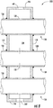
- FIG. 8 provides a cross sectioned side view of a portion of an exemplary fuel nozzle assembly 100 as shown in FIG. 6 or 7 .
- FIG. 8 provides an illustration of an example resonator 150 which can be used in such embodiments.
- resonator 150 may have more than one mixing tube 118 passing through it and each of the mixing tubes 118 passing through the resonator may be in fluid communication with resonator chamber 158 via one or more openings 132 in each mixing tube 118.
- Typically in embodiments such as those illustrated in FIGS. 6 and 7 although more than one mixing tube 118 passes through each resonator 150, less than all of the mixing tubes 118 within a nozzle pass through a resonator 150.
- a first set of mixing tubes may pass through one resonator 150 while a second set of mixing tubes may pass through another resonator 150.
- a first set of mixing tubes 118 may pass through a resonator 150 while a second set of mixing tubes 118 may not.
- the resonator 150 includes first and second sidewalls 152 and 154 and an outer wall 156.
- each tube 118 that passes through resonator 150 may have an outer surface 138 of mixing tube 118 sealingly fixed to the first sidewall 152 and second sidewall 154, such as by brazing or welding.
- a single resonator 150 maybe provided. Further, in embodiments where more than one tube 118 passes through each resonator 150, and in particular where there is only one single resonator 150 per nozzle, for example as in FIGS. 9 and 10 , all of the tubes 118 in the fuel nozzle assembly 100 may pass through and be surrounded by the resonator 150.
- resonator(s) 150 dampens acoustical vibrations in the cantilevered tubes 118 which reduces tube wear at the joint formed between each respective tube 118 and the aft plate 106, thereby reducing the potential for fuel leakage from the fuel plenum 110 and/or prevents the tubes 118 from vibrating against the cap plate 112 during operation of the combustor 16, thus improving tube life.
- the ratio between the tube opening(s) 132 and the volume of resonator chamber 158 may be modified depending on combustion dynamics or mechanical vibrations of a particular gas turbine.
- multiple resonators 150 of various sizes may be provided, e.g., resonators 150 in one fuel nozzle segment may be sized to dampen one frequency range while resonators 150 in an adjacent fuel nozzle segment may be sized for another range.
Landscapes
- Engineering & Computer Science (AREA)
- Chemical & Material Sciences (AREA)
- Combustion & Propulsion (AREA)
- Mechanical Engineering (AREA)
- General Engineering & Computer Science (AREA)
- Hydrogen, Water And Hydrids (AREA)
- Pressure-Spray And Ultrasonic-Wave- Spray Burners (AREA)
Claims (15)
- Ensemble de buse à combustible à tubes groupés (100) comprenant :un corps de plénum de combustible (110) comprenant une plaque avant (104) s'étendant dans une direction radiale, une plaque arrière (106) espacée axialement de la plaque avant (104) et s'étendant dans une direction radiale, un manchon externe (108) s'étendant dans une direction radiale entre la plaque avant (104) et la plaque arrière (106) et un plénum de combustible (110) défini par la plaque avant (104), la plaque arrière (106) et le manchon externe (108) ;une plaque de recouvrement (112) espacée axialement de la plaque arrière (106), un plénum d'air (111) défini entre la plaque arrière (106) et la plaque de recouvrement (112) ;une pluralité de tubes de mélange (118) s'étendant à travers le corps de plénum de combustible (110), chacun des tubes de mélange (118) comprenant une entrée d'air (120), un orifice de combustible (130) en communication fluidique avec le plénum de combustible (110) et une sortie (124) en aval de la plaque arrière (106) ; etau moins un résonateur (150) positionné entre la plaque arrière (106) et la plaque de recouvrement (112) entourant au moins un tube de mélange (118) de la pluralité de tubes de mélange (118), le au moins un résonateur (150) comprenant une première paroi latérale (152) s'étendant dans une direction radiale, une seconde paroi latérale (154) espacée axialement de la première paroi latérale (152) et s'étendant dans une direction radiale, une paroi externe (156) s'étendant dans une direction axiale entre la première paroi latérale (152) et la seconde paroi latérale (154), une chambre de résonateur (158) définie par la première paroi latérale (152), la seconde paroi latérale (154) et la paroi externe (156), au moins une entrée (160) dans la chambre de résonateur (158) étant en communication fluidique avec le plénum d'air (111) ;dans lequel le au moins un tube de mélange (118) entouré par le au moins un résonateur (150) comprend une ouverture (132) en communication fluidique avec la chambre de résonateur (158).
- Ensemble de buse à combustible à tubes groupés (100) selon la revendication 1, dans lequel le au moins un résonateur (150) comprend un nombre de résonateurs (150) égal à la pluralité de tubes de mélange (118), un seul tube de mélange (118) de la pluralité de tubes de mélange (118) s'étend à travers chaque résonateur (150), chaque tube de mélange (118) s'étend en travers un seul des résonateurs (150) et chacun de la pluralité de tubes de mélange (118) comprend en outre une surface externe (138) fixée de manière étanche à la première paroi latérale (152) et à la seconde paroi latérale (154) du résonateur respectif (150) et l'ouverture (132) de chacun de la pluralité de tubes de mélange (118) est disposée dans la surface externe (138) du tube de mélange (118) entre la première paroi latérale (152) et la seconde paroi latérale (154) du résonateur respectif (150).
- Ensemble de buse à combustible à tubes groupés (100) selon la revendication 1, dans lequel le au moins un résonateur (150) comprend moins de résonateurs (150) que de tubes de mélange (118), dans lequel la pluralité de tubes de mélange (118) comprend un premier ensemble de tubes de mélange (118) et un second ensemble de tubes de mélange (118), un seul tube de mélange individuel (118) du premier ensemble de tubes de mélange (118) s'étend à travers chaque résonateur (150), chacun du premier ensemble de tubes de mélange (118) s'étend à travers un seul des résonateurs (150), chacun du premier ensemble de tubes de mélange (118) comprend en outre une surface externe (138) fixée de manière étanche à la première paroi latérale (152) et à la seconde paroi latérale (154) du résonateur respectif (150) et l'ouverture (132) de chacun du premier ensemble de tubes de mélange (118) est disposée dans sa surface externe (138) entre la première paroi latérale (152) et la seconde paroi latérale (154) du résonateur respectif (150) et aucun du second ensemble de tubes de mélange (118) ne s'étend à travers un résonateur (150).
- Ensemble de buse à combustible à tubes groupés (100) selon la revendication 1, dans lequel le au moins un résonateur (150) comprend moins de résonateurs (150) que de tubes de mélange (118) et deux ou plus de tubes de mélange (118) s'étendent à travers chaque résonateur (150), chaque tube de mélange (118) s'étend à travers un seul des résonateurs (150) et chaque tube de mélange (118) comprend en outre une surface externe (138) fixée de manière étanche à la première paroi latérale (152) et à la seconde paroi latérale (154) du résonateur respectif (150) et l'ouverture (132) de chaque tube de mélange (118) est disposée dans sa surface externe (138) entre la première paroi latérale (152) et la seconde paroi latérale (154) du résonateur respectif (150).
- Ensemble de buse à combustible à tubes groupés selon la revendication 1, dans lequel le au moins un résonateur (150) comprend moins de résonateurs (150) que de tubes de mélange (118), deux ou plus de tubes de mélange (118) s'étendent à travers chaque résonateur (150), la pluralité de tubes de mélange (118) comprend un premier ensemble de tubes de mélange (118) et un second ensemble de tubes de mélange (118), chacun du premier ensemble de tubes de mélange (118) s'étend à travers un seul des résonateurs (150), chacun du premier ensemble de tubes de mélange (118) comprend en outre une surface externe (138) fixée de manière étanche à la première paroi latérale (152) et à la seconde paroi latérale (154) du résonateur respectif (150) et l'ouverture (132) de chacun du premier ensemble de tubes de mélange (118) est disposée dans sa surface externe (138) entre la première paroi latérale (152) et la seconde paroi latérale (154) du résonateur respectif (150) et aucun du second ensemble de tubes de mélange (118) ne s'étend à travers un résonateur (150).
- Ensemble de buse à combustible à tubes groupés (100) selon la revendication 1, dans lequel le au moins un résonateur (150) comprend un seul résonateur (150), chacun de la pluralité de tubes de mélange (118) s'étend à travers le résonateur unique (150) et chacun de la pluralité de tubes de mélange (118) comprend en outre une surface externe (138) fixée de manière étanche à la première paroi latérale (152) et à la seconde paroi latérale (154) du résonateur (150) et l'ouverture (132) de chaque tube de mélange (118) est disposée dans sa surface externe (138) à l'intérieur de la chambre de résonateur (158) du résonateur (150).
- Chambre de combustion (16) comprenant :un couvercle d'extrémité (36) couplé à un carter externe (32) ; etun ensemble de buse à combustible à tubes groupés (100) selon la revendication 1, disposé à l'intérieur du carter externe (32) et couplé au couvercle d'extrémité (36).
- Système de combustion selon la revendication 7, dans lequel le au moins un résonateur (150) comprend un nombre de résonateurs (150) égal à la pluralité de tubes de mélange (118), un seul tube de mélange (118) de la pluralité de tubes de mélange (118) s'étend à travers chaque résonateur (150) et chacun de la pluralité de tubes de mélange (118) comprend en outre une surface externe (138) fixée de manière étanche à la première paroi latérale (152) et à la seconde paroi latérale (154) du résonateur respectif (150) et l'ouverture (132) de chacun de la pluralité de tubes de mélange (118) est disposée dans la surface externe (138) du tube de mélange (118) entre la première paroi latérale (152) et la seconde paroi latérale (154) du résonateur respectif (150).
- Chambre de combustion selon la revendication 7, dans lequel le au moins un résonateur (150) comprend moins de résonateurs (150) que de tubes de mélange (118), deux ou plus de tubes de mélange (118) s'étendent à travers chaque résonateur (150), la pluralité de tubes de mélange (118) comprend un premier ensemble de tubes de mélange (118) et un second ensemble de tubes de mélange (118), chacun du premier ensemble de tubes de mélange (118) s'étend à travers un seul des résonateurs (150), chacun du premier ensemble de tubes de mélange (118) comprend en outre une surface externe (138) fixée de manière étanche à la première paroi latérale (152) et à la seconde paroi latérale (154) du résonateur respectif (150) et l'ouverture (132) de chacun du premier ensemble de tubes de mélange (118) est disposée dans sa surface externe (138) entre la première paroi latérale (152) et la seconde paroi latérale (154) du résonateur respectif et aucun du second ensemble de tubes de mélange (118) ne s'étend à travers un résonateur (150).
- Turbine à gaz (10) comprenant :un compresseur (14) ;une turbine (18) ;une chambre de combustion (16) disposée en aval du compresseur (14) et en amont de la turbine (18), la chambre de combustion (16) comprenant :un couvercle d'extrémité (36) couplé à un carter externe (32) ; etun ensemble de buse de combustible à tubes groupés (100) selon la revendication 1, disposé à l'intérieur du carter externe (32) et couplé au couvercle d'extrémité (36).
- Turbine à gaz selon la revendication 10, dans laquelle le au moins un résonateur (150) comprend un nombre de résonateurs (150) égal à la pluralité de tubes de mélange (118), un seul tube de mélange (118) de la pluralité de tubes de mélange (118) s'étend à travers chaque résonateur (150) et chacun de la pluralité de tubes de mélange (118) comprend en outre une surface externe (138) fixée de manière étanche à la première paroi latérale (152) et à la seconde paroi latérale (154) du résonateur respectif (150) et l'ouverture (132) de chacun de la pluralité de tubes de mélange (118) est disposée dans la surface externe (138) du tube de mélange (118) entre la première paroi latérale (152) et la seconde paroi latérale (154) du résonateur respectif (150).
- Turbine à gaz selon la revendication 10, dans laquelle le au moins un résonateur comprend moins de résonateurs (150) que de tubes de mélange (118), la pluralité de tubes de mélange (118) comprend un premier ensemble de tubes de mélange (118) et un second ensemble de tubes de mélange (118), un seul tube de mélange du premier ensemble de tubes de mélange (118) s'étend à travers chaque résonateur, chacun du premier ensemble de tubes de mélange (118) comprend en outre une surface externe (138) fixée de manière étanche à la première paroi latérale (152) et à la seconde paroi latérale (154) du résonateur respectif (150) et l'ouverture (132) de chacun du premier ensemble de tubes de mélange (118) est disposée dans sa surface externe (138) entre la première paroi latérale (152) et la seconde paroi latérale (154) du résonateur respectif (150) et aucun du second ensemble de tubes de mélange (118) ne s'étend à travers un résonateur (150).
- Turbine à gaz selon la revendication 10, dans laquelle le au moins un résonateur (150) comprend moins de résonateurs (150) que de tubes de mélange (118) et deux ou plus de tubes de mélange (118) s'étendent à travers chaque résonateur, chaque tube de mélange s'étend à travers un seul des résonateurs (150) et chaque tube de mélange (118) comprend en outre une surface externe (138) fixée de manière étanche à la première paroi latérale (152) et à la seconde paroi latérale (154) du résonateur respectif (150) et l'ouverture (132) de chaque tube de mélange (118) est disposée dans sa surface externe (138) entre la première paroi latérale (152) et la seconde paroi latérale (154) du résonateur respectif (150).
- Turbine à gaz selon la revendication 10, dans laquelle le au moins un résonateur (150) comprend moins de résonateurs (150) que de tubes de mélange (118), deux ou plus de tubes de mélange (118) s'étendent à travers chaque résonateur, la pluralité de tubes de mélange (118) comprend un premier ensemble de tubes de mélange (118) et un second ensemble de tubes de mélange (118), chacun du premier ensemble de tubes de mélange (118) s'étend à travers un seul des résonateurs, chacun du premier ensemble de tubes de mélange (118) comprend en outre une surface externe (138) fixée de manière étanche à la première paroi latérale (152) et à la seconde paroi latérale (154) du résonateur respectif (150) et l'ouverture (132) de chacun du premier ensemble de tubes de mélange (118) est disposée dans sa surface externe (138) entre la première paroi latérale (152) et la seconde paroi latérale (154) du résonateur respectif (150) et aucun du second ensemble de tubes de mélange (118) ne s'étend à travers un résonateur (150).
- Turbine à gaz selon la revendication 10, dans laquelle le au moins un résonateur (150) comprend un seul résonateur, chacun de la pluralité de tubes de mélange (118) s'étend à travers l'unique résonateur (150) et chacun de la pluralité de tubes de mélange (118) comprend en outre une surface externe (138) fixée de manière étanche à la première paroi latérale (152) et à la seconde paroi latérale (154) du résonateur (150) et l'ouverture (132) de chaque tube de mélange est disposée dans sa surface externe (138) à l'intérieur de la chambre de résonateur (158).
Applications Claiming Priority (1)
| Application Number | Priority Date | Filing Date | Title |
|---|---|---|---|
| US15/256,771 US10145561B2 (en) | 2016-09-06 | 2016-09-06 | Fuel nozzle assembly with resonator |
Publications (2)
| Publication Number | Publication Date |
|---|---|
| EP3290805A1 EP3290805A1 (fr) | 2018-03-07 |
| EP3290805B1 true EP3290805B1 (fr) | 2019-04-10 |
Family
ID=59790990
Family Applications (1)
| Application Number | Title | Priority Date | Filing Date |
|---|---|---|---|
| EP17189350.6A Not-in-force EP3290805B1 (fr) | 2016-09-06 | 2017-09-05 | Ensemble de buse de combustible comportant un résonateur |
Country Status (4)
| Country | Link |
|---|---|
| US (1) | US10145561B2 (fr) |
| EP (1) | EP3290805B1 (fr) |
| JP (1) | JP7051329B2 (fr) |
| CN (1) | CN107796015B (fr) |
Families Citing this family (11)
| Publication number | Priority date | Publication date | Assignee | Title |
|---|---|---|---|---|
| US10386074B2 (en) * | 2016-12-09 | 2019-08-20 | Solar Turbines Incorporated | Injector head with a resonator for a gas turbine engine |
| DE102019205540A1 (de) | 2019-04-17 | 2020-10-22 | Siemens Aktiengesellschaft | Resonator, Verfahren zur Herstellung eines solchen sowie mit einem solchen versehene Brenneranordnung |
| DE102020200204A1 (de) * | 2020-01-09 | 2021-07-15 | Siemens Aktiengesellschaft | Keramischer Resonator für Brennkammersysteme und Brennkammersystem |
| US12553385B2 (en) * | 2020-03-30 | 2026-02-17 | Ge Vernova Infrastructure Technology Llc | Compact turbomachine combustor |
| EP4426970A2 (fr) * | 2021-11-03 | 2024-09-11 | Power Systems Mfg., LLC | Injecteur pilote multitube ayant un ancrage de flamme pour un moteur à turbine à gaz |
| KR102619152B1 (ko) | 2022-02-21 | 2023-12-27 | 두산에너빌리티 주식회사 | 연소기용 노즐, 연소기, 및 이를 포함하는 가스 터빈 |
| JP2023148761A (ja) * | 2022-03-30 | 2023-10-13 | 三菱重工業株式会社 | 燃焼器及びガスタービン |
| CN117109030B (zh) * | 2022-05-16 | 2025-09-19 | 通用电气公司 | 燃烧器衬里中的热声阻尼器 |
| US12379108B2 (en) | 2023-01-06 | 2025-08-05 | Ge Vernova Infrastructure Technology Llc | Method of operating gas turbine combustor with multiple fuel stages |
| US12560327B2 (en) | 2023-01-06 | 2026-02-24 | Ge Vernova Infrastructure Technology Llc | Multi-stage axial fuel injection system with discrete air supplies |
| DE102023132050A1 (de) * | 2023-11-17 | 2025-05-22 | Man Energy Solutions Se | Gasturbinenbrenner |
Family Cites Families (72)
| Publication number | Priority date | Publication date | Assignee | Title |
|---|---|---|---|---|
| US3771500A (en) | 1971-04-29 | 1973-11-13 | H Shakiba | Rotary engine |
| US4104873A (en) | 1976-11-29 | 1978-08-08 | The United States Of America As Represented By The Administrator Of The United States National Aeronautics And Space Administration | Fuel delivery system including heat exchanger means |
| US4412414A (en) | 1980-09-22 | 1983-11-01 | General Motors Corporation | Heavy fuel combustor |
| SE455438B (sv) | 1986-11-24 | 1988-07-11 | Aga Ab | Sett att senka en brennares flamtemperatur samt brennare med munstycken for oxygen resp brensle |
| DE4041628A1 (de) | 1990-12-22 | 1992-07-02 | Daimler Benz Ag | Gemischverdichtende brennkraftmaschine mit sekundaerlufteinblasung und mit luftmassenmessung im saugrohr |
| DE4100657A1 (de) | 1991-01-11 | 1992-07-16 | Rothenberger Werkzeuge Masch | Tragbarer brenner fuer brenngas mit zwei mischrohren |
| FR2689964B1 (fr) | 1992-04-08 | 1994-05-27 | Snecma | Chambre de combustion munie d'un fond generateur de premelange. |
| US5439532A (en) | 1992-06-30 | 1995-08-08 | Jx Crystals, Inc. | Cylindrical electric power generator using low bandgap thermophotovolatic cells and a regenerative hydrocarbon gas burner |
| FR2712378B1 (fr) | 1993-11-10 | 1995-12-29 | Stein Industrie | Réacteur à lit fluidisé circulant à extensions de surface d'échange thermique. |
| FR2717250B1 (fr) | 1994-03-10 | 1996-04-12 | Snecma | Système d'injection à prémélange. |
| KR100550689B1 (ko) | 1998-02-10 | 2006-02-08 | 제너럴 일렉트릭 캄파니 | 가스 터빈의 연소 시스템용 버너 및 연료와 공기의 예비혼합 방법 |
| US6098407A (en) | 1998-06-08 | 2000-08-08 | United Technologies Corporation | Premixing fuel injector with improved secondary fuel-air injection |
| DE59810347D1 (de) * | 1998-09-10 | 2004-01-15 | Alstom Switzerland Ltd | Schwingungsdämpfung in Brennkammern |
| US6123542A (en) | 1998-11-03 | 2000-09-26 | American Air Liquide | Self-cooled oxygen-fuel burner for use in high-temperature and high-particulate furnaces |
| DE19851636A1 (de) * | 1998-11-10 | 2000-05-11 | Asea Brown Boveri | Dämpfungsvorrichtung zur Reduzierung der Schwingungsamplitude akustischer Wellen für einen Brenner |
| US6358040B1 (en) | 2000-03-17 | 2002-03-19 | Precision Combustion, Inc. | Method and apparatus for a fuel-rich catalytic reactor |
| US6351947B1 (en) * | 2000-04-04 | 2002-03-05 | Abb Alstom Power (Schweiz) | Combustion chamber for a gas turbine |
| WO2002021044A1 (fr) | 2000-09-07 | 2002-03-14 | John Zink Company, L.L.C. | Bruleur a paroi radiante a haute capacite/faible emission de no¿x? |
| US6530221B1 (en) | 2000-09-21 | 2003-03-11 | Siemens Westinghouse Power Corporation | Modular resonators for suppressing combustion instabilities in gas turbine power plants |
| GB2390150A (en) * | 2002-06-26 | 2003-12-31 | Alstom | Reheat combustion system for a gas turbine including an accoustic screen |
| US6820431B2 (en) * | 2002-10-31 | 2004-11-23 | General Electric Company | Acoustic impedance-matched fuel nozzle device and tunable fuel injection resonator assembly |
| US6931862B2 (en) | 2003-04-30 | 2005-08-23 | Hamilton Sundstrand Corporation | Combustor system for an expendable gas turbine engine |
| US7117974B2 (en) * | 2004-05-14 | 2006-10-10 | Visteon Global Technologies, Inc. | Electronically controlled dual chamber variable resonator |
| US7003958B2 (en) | 2004-06-30 | 2006-02-28 | General Electric Company | Multi-sided diffuser for a venturi in a fuel injector for a gas turbine |
| US6983600B1 (en) | 2004-06-30 | 2006-01-10 | General Electric Company | Multi-venturi tube fuel injector for gas turbine combustors |
| US7007478B2 (en) | 2004-06-30 | 2006-03-07 | General Electric Company | Multi-venturi tube fuel injector for a gas turbine combustor |
| US7464552B2 (en) * | 2004-07-02 | 2008-12-16 | Siemens Energy, Inc. | Acoustically stiffened gas-turbine fuel nozzle |
| US20080016876A1 (en) | 2005-06-02 | 2008-01-24 | General Electric Company | Method and apparatus for reducing gas turbine engine emissions |
| US7752850B2 (en) | 2005-07-01 | 2010-07-13 | Siemens Energy, Inc. | Controlled pilot oxidizer for a gas turbine combustor |
| US7413053B2 (en) | 2006-01-25 | 2008-08-19 | Siemens Power Generation, Inc. | Acoustic resonator with impingement cooling tubes |
| US7631499B2 (en) | 2006-08-03 | 2009-12-15 | Siemens Energy, Inc. | Axially staged combustion system for a gas turbine engine |
| US8127546B2 (en) * | 2007-05-31 | 2012-03-06 | Solar Turbines Inc. | Turbine engine fuel injector with helmholtz resonators |
| US8127547B2 (en) | 2007-06-07 | 2012-03-06 | United Technologies Corporation | Gas turbine engine with air and fuel cooling system |
| US20090297996A1 (en) | 2008-05-28 | 2009-12-03 | Advanced Burner Technologies Corporation | Fuel injector for low NOx furnace |
| US8147121B2 (en) | 2008-07-09 | 2012-04-03 | General Electric Company | Pre-mixing apparatus for a turbine engine |
| US8186166B2 (en) | 2008-07-29 | 2012-05-29 | General Electric Company | Hybrid two fuel system nozzle with a bypass connecting the two fuel systems |
| US8112999B2 (en) | 2008-08-05 | 2012-02-14 | General Electric Company | Turbomachine injection nozzle including a coolant delivery system |
| FI122203B (fi) | 2008-09-11 | 2011-10-14 | Raute Oyj | Aaltojohtoelementti |
| US7886991B2 (en) | 2008-10-03 | 2011-02-15 | General Electric Company | Premixed direct injection nozzle |
| US8007274B2 (en) | 2008-10-10 | 2011-08-30 | General Electric Company | Fuel nozzle assembly |
| US8327642B2 (en) | 2008-10-21 | 2012-12-11 | General Electric Company | Multiple tube premixing device |
| US8209986B2 (en) | 2008-10-29 | 2012-07-03 | General Electric Company | Multi-tube thermal fuse for nozzle protection from a flame holding or flashback event |
| US9140454B2 (en) | 2009-01-23 | 2015-09-22 | General Electric Company | Bundled multi-tube nozzle for a turbomachine |
| US8539773B2 (en) | 2009-02-04 | 2013-09-24 | General Electric Company | Premixed direct injection nozzle for highly reactive fuels |
| US8424311B2 (en) | 2009-02-27 | 2013-04-23 | General Electric Company | Premixed direct injection disk |
| US8234871B2 (en) | 2009-03-18 | 2012-08-07 | General Electric Company | Method and apparatus for delivery of a fuel and combustion air mixture to a gas turbine engine using fuel distribution grooves in a manifold disk with discrete air passages |
| US8157189B2 (en) | 2009-04-03 | 2012-04-17 | General Electric Company | Premixing direct injector |
| US8333075B2 (en) * | 2009-04-16 | 2012-12-18 | General Electric Company | Gas turbine premixer with internal cooling |
| US8607568B2 (en) | 2009-05-14 | 2013-12-17 | General Electric Company | Dry low NOx combustion system with pre-mixed direct-injection secondary fuel nozzle |
| US8789372B2 (en) * | 2009-07-08 | 2014-07-29 | General Electric Company | Injector with integrated resonator |
| US8616002B2 (en) | 2009-07-23 | 2013-12-31 | General Electric Company | Gas turbine premixing systems |
| US8794545B2 (en) | 2009-09-25 | 2014-08-05 | General Electric Company | Internal baffling for fuel injector |
| US8365532B2 (en) | 2009-09-30 | 2013-02-05 | General Electric Company | Apparatus and method for a gas turbine nozzle |
| US8276385B2 (en) | 2009-10-08 | 2012-10-02 | General Electric Company | Staged multi-tube premixing injector |
| US20110089266A1 (en) | 2009-10-16 | 2011-04-21 | General Electric Company | Fuel nozzle lip seals |
| US20120058437A1 (en) | 2010-09-08 | 2012-03-08 | General Electric Company | Apparatus and method for mixing fuel in a gas turbine nozzle |
| US8800289B2 (en) | 2010-09-08 | 2014-08-12 | General Electric Company | Apparatus and method for mixing fuel in a gas turbine nozzle |
| US9010083B2 (en) | 2011-02-03 | 2015-04-21 | General Electric Company | Apparatus for mixing fuel in a gas turbine |
| US9341375B2 (en) * | 2011-07-22 | 2016-05-17 | General Electric Company | System for damping oscillations in a turbine combustor |
| US9388985B2 (en) | 2011-07-29 | 2016-07-12 | General Electric Company | Premixing apparatus for gas turbine system |
| US9506654B2 (en) * | 2011-08-19 | 2016-11-29 | General Electric Company | System and method for reducing combustion dynamics in a combustor |
| CN103842727A (zh) * | 2011-09-22 | 2014-06-04 | 通用电气公司 | 用于衰减低频动力的燃烧器帽 |
| US8984887B2 (en) | 2011-09-25 | 2015-03-24 | General Electric Company | Combustor and method for supplying fuel to a combustor |
| US20130283810A1 (en) * | 2012-04-30 | 2013-10-31 | General Electric Company | Combustion nozzle and a related method thereof |
| US9709277B2 (en) | 2012-05-15 | 2017-07-18 | General Electric Company | Fuel plenum premixing tube with surface treatment |
| US9249734B2 (en) | 2012-07-10 | 2016-02-02 | General Electric Company | Combustor |
| US9353950B2 (en) * | 2012-12-10 | 2016-05-31 | General Electric Company | System for reducing combustion dynamics and NOx in a combustor |
| US20150167980A1 (en) * | 2013-12-18 | 2015-06-18 | Jared M. Pent | Axial stage injection dual frequency resonator for a combustor of a gas turbine engine |
| US20150285502A1 (en) * | 2014-04-08 | 2015-10-08 | General Electric Company | Fuel nozzle shroud and method of manufacturing the shroud |
| EP3117148B1 (fr) | 2014-05-19 | 2018-06-06 | Siemens Aktiengesellschaft | Système de combustion avec résonateur |
| US9631816B2 (en) * | 2014-11-26 | 2017-04-25 | General Electric Company | Bundled tube fuel nozzle |
| US10094569B2 (en) * | 2014-12-11 | 2018-10-09 | General Electric Company | Injecting apparatus with reheat combustor and turbomachine |
-
2016
- 2016-09-06 US US15/256,771 patent/US10145561B2/en active Active
-
2017
- 2017-08-23 JP JP2017159842A patent/JP7051329B2/ja active Active
- 2017-09-05 EP EP17189350.6A patent/EP3290805B1/fr not_active Not-in-force
- 2017-09-06 CN CN201710795963.9A patent/CN107796015B/zh not_active Expired - Fee Related
Non-Patent Citations (1)
| Title |
|---|
| None * |
Also Published As
| Publication number | Publication date |
|---|---|
| CN107796015A (zh) | 2018-03-13 |
| US10145561B2 (en) | 2018-12-04 |
| US20180066847A1 (en) | 2018-03-08 |
| JP2018040560A (ja) | 2018-03-15 |
| EP3290805A1 (fr) | 2018-03-07 |
| JP7051329B2 (ja) | 2022-04-11 |
| CN107796015B (zh) | 2021-03-12 |
Similar Documents
| Publication | Publication Date | Title |
|---|---|---|
| EP3290805B1 (fr) | Ensemble de buse de combustible comportant un résonateur | |
| EP3214373B1 (fr) | Injecteur de carburant à faisceau tubulaire avec refroidissement interne | |
| EP3171088B1 (fr) | Ensemble injecteur de carburant à faisceau tubulaire ayant une capacité de combustible liquide | |
| US10215413B2 (en) | Bundled tube fuel nozzle with vibration damping | |
| US11041625B2 (en) | Fuel nozzle with narrow-band acoustic damper | |
| US10415831B2 (en) | Combustor assembly with mounted auxiliary component | |
| US9249734B2 (en) | Combustor | |
| US20180209651A1 (en) | Combustor with axially staged fuel injector assembly | |
| US12050062B2 (en) | Stacked cooling assembly for gas turbine combustor | |
| CN103423770A (zh) | 燃料喷嘴帽 | |
| US20170343216A1 (en) | Fuel Nozzle Assembly with Tube Damping | |
| JP6001854B2 (ja) | タービンエンジン用燃焼器組立体及びその組み立て方法 | |
| US20140318140A1 (en) | Premixer assembly and mechanism for altering natural frequency of a gas turbine combustor | |
| EP3309457B1 (fr) | Système d'atténuation de la dynamique de combustion | |
| EP3586061B1 (fr) | Ensemble couvercle d'extrémité pour chambre de combustion | |
| EP4067746B1 (fr) | Chambre de combustion ayant une stimulation de sillage | |
| US20180363905A1 (en) | Fuel nozzle assembly for reducing multiple tone combustion dynamics | |
| US10408455B2 (en) | Fuel nozzle assembly with fuel inlet slots | |
| US11774099B2 (en) | Gas turbine fuel nozzle tip comprising an impingement wall |
Legal Events
| Date | Code | Title | Description |
|---|---|---|---|
| PUAI | Public reference made under article 153(3) epc to a published international application that has entered the european phase |
Free format text: ORIGINAL CODE: 0009012 |
|
| STAA | Information on the status of an ep patent application or granted ep patent |
Free format text: STATUS: THE APPLICATION HAS BEEN PUBLISHED |
|
| AK | Designated contracting states |
Kind code of ref document: A1 Designated state(s): AL AT BE BG CH CY CZ DE DK EE ES FI FR GB GR HR HU IE IS IT LI LT LU LV MC MK MT NL NO PL PT RO RS SE SI SK SM TR |
|
| AX | Request for extension of the european patent |
Extension state: BA ME |
|
| STAA | Information on the status of an ep patent application or granted ep patent |
Free format text: STATUS: REQUEST FOR EXAMINATION WAS MADE |
|
| 17P | Request for examination filed |
Effective date: 20180907 |
|
| RBV | Designated contracting states (corrected) |
Designated state(s): AL AT BE BG CH CY CZ DE DK EE ES FI FR GB GR HR HU IE IS IT LI LT LU LV MC MK MT NL NO PL PT RO RS SE SI SK SM TR |
|
| GRAP | Despatch of communication of intention to grant a patent |
Free format text: ORIGINAL CODE: EPIDOSNIGR1 |
|
| STAA | Information on the status of an ep patent application or granted ep patent |
Free format text: STATUS: GRANT OF PATENT IS INTENDED |
|
| RIC1 | Information provided on ipc code assigned before grant |
Ipc: F23R 3/28 20060101AFI20181121BHEP |
|
| INTG | Intention to grant announced |
Effective date: 20181207 |
|
| GRAS | Grant fee paid |
Free format text: ORIGINAL CODE: EPIDOSNIGR3 |
|
| GRAA | (expected) grant |
Free format text: ORIGINAL CODE: 0009210 |
|
| STAA | Information on the status of an ep patent application or granted ep patent |
Free format text: STATUS: THE PATENT HAS BEEN GRANTED |
|
| AK | Designated contracting states |
Kind code of ref document: B1 Designated state(s): AL AT BE BG CH CY CZ DE DK EE ES FI FR GB GR HR HU IE IS IT LI LT LU LV MC MK MT NL NO PL PT RO RS SE SI SK SM TR |
|
| REG | Reference to a national code |
Ref country code: GB Ref legal event code: FG4D |
|
| REG | Reference to a national code |
Ref country code: CH Ref legal event code: EP Ref country code: AT Ref legal event code: REF Ref document number: 1119203 Country of ref document: AT Kind code of ref document: T Effective date: 20190415 |
|
| REG | Reference to a national code |
Ref country code: IE Ref legal event code: FG4D |
|
| REG | Reference to a national code |
Ref country code: DE Ref legal event code: R096 Ref document number: 602017003203 Country of ref document: DE |
|
| REG | Reference to a national code |
Ref country code: NL Ref legal event code: MP Effective date: 20190410 |
|
| REG | Reference to a national code |
Ref country code: LT Ref legal event code: MG4D |
|
| REG | Reference to a national code |
Ref country code: AT Ref legal event code: MK05 Ref document number: 1119203 Country of ref document: AT Kind code of ref document: T Effective date: 20190410 |
|
| PG25 | Lapsed in a contracting state [announced via postgrant information from national office to epo] |
Ref country code: NL Free format text: LAPSE BECAUSE OF FAILURE TO SUBMIT A TRANSLATION OF THE DESCRIPTION OR TO PAY THE FEE WITHIN THE PRESCRIBED TIME-LIMIT Effective date: 20190410 |
|
| PG25 | Lapsed in a contracting state [announced via postgrant information from national office to epo] |
Ref country code: FI Free format text: LAPSE BECAUSE OF FAILURE TO SUBMIT A TRANSLATION OF THE DESCRIPTION OR TO PAY THE FEE WITHIN THE PRESCRIBED TIME-LIMIT Effective date: 20190410 Ref country code: LT Free format text: LAPSE BECAUSE OF FAILURE TO SUBMIT A TRANSLATION OF THE DESCRIPTION OR TO PAY THE FEE WITHIN THE PRESCRIBED TIME-LIMIT Effective date: 20190410 Ref country code: AL Free format text: LAPSE BECAUSE OF FAILURE TO SUBMIT A TRANSLATION OF THE DESCRIPTION OR TO PAY THE FEE WITHIN THE PRESCRIBED TIME-LIMIT Effective date: 20190410 Ref country code: ES Free format text: LAPSE BECAUSE OF FAILURE TO SUBMIT A TRANSLATION OF THE DESCRIPTION OR TO PAY THE FEE WITHIN THE PRESCRIBED TIME-LIMIT Effective date: 20190410 Ref country code: HR Free format text: LAPSE BECAUSE OF FAILURE TO SUBMIT A TRANSLATION OF THE DESCRIPTION OR TO PAY THE FEE WITHIN THE PRESCRIBED TIME-LIMIT Effective date: 20190410 Ref country code: PT Free format text: LAPSE BECAUSE OF FAILURE TO SUBMIT A TRANSLATION OF THE DESCRIPTION OR TO PAY THE FEE WITHIN THE PRESCRIBED TIME-LIMIT Effective date: 20190910 Ref country code: SE Free format text: LAPSE BECAUSE OF FAILURE TO SUBMIT A TRANSLATION OF THE DESCRIPTION OR TO PAY THE FEE WITHIN THE PRESCRIBED TIME-LIMIT Effective date: 20190410 Ref country code: NO Free format text: LAPSE BECAUSE OF FAILURE TO SUBMIT A TRANSLATION OF THE DESCRIPTION OR TO PAY THE FEE WITHIN THE PRESCRIBED TIME-LIMIT Effective date: 20190710 |
|
| PG25 | Lapsed in a contracting state [announced via postgrant information from national office to epo] |
Ref country code: GR Free format text: LAPSE BECAUSE OF FAILURE TO SUBMIT A TRANSLATION OF THE DESCRIPTION OR TO PAY THE FEE WITHIN THE PRESCRIBED TIME-LIMIT Effective date: 20190711 Ref country code: PL Free format text: LAPSE BECAUSE OF FAILURE TO SUBMIT A TRANSLATION OF THE DESCRIPTION OR TO PAY THE FEE WITHIN THE PRESCRIBED TIME-LIMIT Effective date: 20190410 Ref country code: RS Free format text: LAPSE BECAUSE OF FAILURE TO SUBMIT A TRANSLATION OF THE DESCRIPTION OR TO PAY THE FEE WITHIN THE PRESCRIBED TIME-LIMIT Effective date: 20190410 Ref country code: LV Free format text: LAPSE BECAUSE OF FAILURE TO SUBMIT A TRANSLATION OF THE DESCRIPTION OR TO PAY THE FEE WITHIN THE PRESCRIBED TIME-LIMIT Effective date: 20190410 Ref country code: BG Free format text: LAPSE BECAUSE OF FAILURE TO SUBMIT A TRANSLATION OF THE DESCRIPTION OR TO PAY THE FEE WITHIN THE PRESCRIBED TIME-LIMIT Effective date: 20190710 |
|
| PG25 | Lapsed in a contracting state [announced via postgrant information from national office to epo] |
Ref country code: AT Free format text: LAPSE BECAUSE OF FAILURE TO SUBMIT A TRANSLATION OF THE DESCRIPTION OR TO PAY THE FEE WITHIN THE PRESCRIBED TIME-LIMIT Effective date: 20190410 Ref country code: IS Free format text: LAPSE BECAUSE OF FAILURE TO SUBMIT A TRANSLATION OF THE DESCRIPTION OR TO PAY THE FEE WITHIN THE PRESCRIBED TIME-LIMIT Effective date: 20190810 |
|
| REG | Reference to a national code |
Ref country code: DE Ref legal event code: R097 Ref document number: 602017003203 Country of ref document: DE |
|
| PG25 | Lapsed in a contracting state [announced via postgrant information from national office to epo] |
Ref country code: SK Free format text: LAPSE BECAUSE OF FAILURE TO SUBMIT A TRANSLATION OF THE DESCRIPTION OR TO PAY THE FEE WITHIN THE PRESCRIBED TIME-LIMIT Effective date: 20190410 Ref country code: RO Free format text: LAPSE BECAUSE OF FAILURE TO SUBMIT A TRANSLATION OF THE DESCRIPTION OR TO PAY THE FEE WITHIN THE PRESCRIBED TIME-LIMIT Effective date: 20190410 Ref country code: CZ Free format text: LAPSE BECAUSE OF FAILURE TO SUBMIT A TRANSLATION OF THE DESCRIPTION OR TO PAY THE FEE WITHIN THE PRESCRIBED TIME-LIMIT Effective date: 20190410 Ref country code: EE Free format text: LAPSE BECAUSE OF FAILURE TO SUBMIT A TRANSLATION OF THE DESCRIPTION OR TO PAY THE FEE WITHIN THE PRESCRIBED TIME-LIMIT Effective date: 20190410 Ref country code: DK Free format text: LAPSE BECAUSE OF FAILURE TO SUBMIT A TRANSLATION OF THE DESCRIPTION OR TO PAY THE FEE WITHIN THE PRESCRIBED TIME-LIMIT Effective date: 20190410 |
|
| PLBE | No opposition filed within time limit |
Free format text: ORIGINAL CODE: 0009261 |
|
| STAA | Information on the status of an ep patent application or granted ep patent |
Free format text: STATUS: NO OPPOSITION FILED WITHIN TIME LIMIT |
|
| PG25 | Lapsed in a contracting state [announced via postgrant information from national office to epo] |
Ref country code: IT Free format text: LAPSE BECAUSE OF FAILURE TO SUBMIT A TRANSLATION OF THE DESCRIPTION OR TO PAY THE FEE WITHIN THE PRESCRIBED TIME-LIMIT Effective date: 20190410 Ref country code: SM Free format text: LAPSE BECAUSE OF FAILURE TO SUBMIT A TRANSLATION OF THE DESCRIPTION OR TO PAY THE FEE WITHIN THE PRESCRIBED TIME-LIMIT Effective date: 20190410 |
|
| 26N | No opposition filed |
Effective date: 20200113 |
|
| PG25 | Lapsed in a contracting state [announced via postgrant information from national office to epo] |
Ref country code: TR Free format text: LAPSE BECAUSE OF FAILURE TO SUBMIT A TRANSLATION OF THE DESCRIPTION OR TO PAY THE FEE WITHIN THE PRESCRIBED TIME-LIMIT Effective date: 20190410 |
|
| PG25 | Lapsed in a contracting state [announced via postgrant information from national office to epo] |
Ref country code: MC Free format text: LAPSE BECAUSE OF FAILURE TO SUBMIT A TRANSLATION OF THE DESCRIPTION OR TO PAY THE FEE WITHIN THE PRESCRIBED TIME-LIMIT Effective date: 20190410 Ref country code: SI Free format text: LAPSE BECAUSE OF FAILURE TO SUBMIT A TRANSLATION OF THE DESCRIPTION OR TO PAY THE FEE WITHIN THE PRESCRIBED TIME-LIMIT Effective date: 20190410 |
|
| PG25 | Lapsed in a contracting state [announced via postgrant information from national office to epo] |
Ref country code: LU Free format text: LAPSE BECAUSE OF NON-PAYMENT OF DUE FEES Effective date: 20190905 Ref country code: IE Free format text: LAPSE BECAUSE OF NON-PAYMENT OF DUE FEES Effective date: 20190905 |
|
| REG | Reference to a national code |
Ref country code: BE Ref legal event code: MM Effective date: 20190930 |
|
| PG25 | Lapsed in a contracting state [announced via postgrant information from national office to epo] |
Ref country code: BE Free format text: LAPSE BECAUSE OF NON-PAYMENT OF DUE FEES Effective date: 20190930 |
|
| PG25 | Lapsed in a contracting state [announced via postgrant information from national office to epo] |
Ref country code: FR Free format text: LAPSE BECAUSE OF NON-PAYMENT OF DUE FEES Effective date: 20190930 |
|
| PGFP | Annual fee paid to national office [announced via postgrant information from national office to epo] |
Ref country code: DE Payment date: 20200819 Year of fee payment: 4 |
|
| REG | Reference to a national code |
Ref country code: CH Ref legal event code: PL |
|
| PG25 | Lapsed in a contracting state [announced via postgrant information from national office to epo] |
Ref country code: CY Free format text: LAPSE BECAUSE OF FAILURE TO SUBMIT A TRANSLATION OF THE DESCRIPTION OR TO PAY THE FEE WITHIN THE PRESCRIBED TIME-LIMIT Effective date: 20190410 |
|
| PG25 | Lapsed in a contracting state [announced via postgrant information from national office to epo] |
Ref country code: MT Free format text: LAPSE BECAUSE OF FAILURE TO SUBMIT A TRANSLATION OF THE DESCRIPTION OR TO PAY THE FEE WITHIN THE PRESCRIBED TIME-LIMIT Effective date: 20190410 Ref country code: HU Free format text: LAPSE BECAUSE OF FAILURE TO SUBMIT A TRANSLATION OF THE DESCRIPTION OR TO PAY THE FEE WITHIN THE PRESCRIBED TIME-LIMIT; INVALID AB INITIO Effective date: 20170905 |
|
| PG25 | Lapsed in a contracting state [announced via postgrant information from national office to epo] |
Ref country code: LI Free format text: LAPSE BECAUSE OF NON-PAYMENT OF DUE FEES Effective date: 20200930 Ref country code: CH Free format text: LAPSE BECAUSE OF NON-PAYMENT OF DUE FEES Effective date: 20200930 |
|
| REG | Reference to a national code |
Ref country code: DE Ref legal event code: R119 Ref document number: 602017003203 Country of ref document: DE |
|
| GBPC | Gb: european patent ceased through non-payment of renewal fee |
Effective date: 20210905 |
|
| PG25 | Lapsed in a contracting state [announced via postgrant information from national office to epo] |
Ref country code: MK Free format text: LAPSE BECAUSE OF FAILURE TO SUBMIT A TRANSLATION OF THE DESCRIPTION OR TO PAY THE FEE WITHIN THE PRESCRIBED TIME-LIMIT Effective date: 20190410 |
|
| PG25 | Lapsed in a contracting state [announced via postgrant information from national office to epo] |
Ref country code: GB Free format text: LAPSE BECAUSE OF NON-PAYMENT OF DUE FEES Effective date: 20210905 Ref country code: DE Free format text: LAPSE BECAUSE OF NON-PAYMENT OF DUE FEES Effective date: 20220401 |