EP3290810B1 - Haushaltegeräteleuchte - Google Patents
Haushaltegeräteleuchte Download PDFInfo
- Publication number
- EP3290810B1 EP3290810B1 EP17187080.1A EP17187080A EP3290810B1 EP 3290810 B1 EP3290810 B1 EP 3290810B1 EP 17187080 A EP17187080 A EP 17187080A EP 3290810 B1 EP3290810 B1 EP 3290810B1
- Authority
- EP
- European Patent Office
- Prior art keywords
- light
- reflector
- lamp
- domestic appliance
- axis
- Prior art date
- Legal status (The legal status is an assumption and is not a legal conclusion. Google has not performed a legal analysis and makes no representation as to the accuracy of the status listed.)
- Active
Links
Images




Classifications
-
- F—MECHANICAL ENGINEERING; LIGHTING; HEATING; WEAPONS; BLASTING
- F24—HEATING; RANGES; VENTILATING
- F24C—DOMESTIC STOVES OR RANGES ; DETAILS OF DOMESTIC STOVES OR RANGES, OF GENERAL APPLICATION
- F24C15/00—Details
- F24C15/008—Illumination for oven cavities
-
- F—MECHANICAL ENGINEERING; LIGHTING; HEATING; WEAPONS; BLASTING
- F21—LIGHTING
- F21K—NON-ELECTRIC LIGHT SOURCES USING LUMINESCENCE; LIGHT SOURCES USING ELECTROCHEMILUMINESCENCE; LIGHT SOURCES USING CHARGES OF COMBUSTIBLE MATERIAL; LIGHT SOURCES USING SEMICONDUCTOR DEVICES AS LIGHT-GENERATING ELEMENTS; LIGHT SOURCES NOT OTHERWISE PROVIDED FOR
- F21K9/00—Light sources using semiconductor devices as light-generating elements, e.g. using light-emitting diodes [LED] or lasers
- F21K9/20—Light sources comprising attachment means
- F21K9/23—Retrofit light sources for lighting devices with a single fitting for each light source, e.g. for substitution of incandescent lamps with bayonet or threaded fittings
- F21K9/233—Retrofit light sources for lighting devices with a single fitting for each light source, e.g. for substitution of incandescent lamps with bayonet or threaded fittings specially adapted for generating a spot light distribution, e.g. for substitution of reflector lamps
-
- F—MECHANICAL ENGINEERING; LIGHTING; HEATING; WEAPONS; BLASTING
- F21—LIGHTING
- F21K—NON-ELECTRIC LIGHT SOURCES USING LUMINESCENCE; LIGHT SOURCES USING ELECTROCHEMILUMINESCENCE; LIGHT SOURCES USING CHARGES OF COMBUSTIBLE MATERIAL; LIGHT SOURCES USING SEMICONDUCTOR DEVICES AS LIGHT-GENERATING ELEMENTS; LIGHT SOURCES NOT OTHERWISE PROVIDED FOR
- F21K9/00—Light sources using semiconductor devices as light-generating elements, e.g. using light-emitting diodes [LED] or lasers
- F21K9/60—Optical arrangements integrated in the light source, e.g. for improving the colour rendering index or the light extraction
- F21K9/61—Optical arrangements integrated in the light source, e.g. for improving the colour rendering index or the light extraction using light guides
-
- F—MECHANICAL ENGINEERING; LIGHTING; HEATING; WEAPONS; BLASTING
- F21—LIGHTING
- F21V—FUNCTIONAL FEATURES OR DETAILS OF LIGHTING DEVICES OR SYSTEMS THEREOF; STRUCTURAL COMBINATIONS OF LIGHTING DEVICES WITH OTHER ARTICLES, NOT OTHERWISE PROVIDED FOR
- F21V13/00—Producing particular characteristics or distribution of the light emitted by means of a combination of elements specified in two or more of main groups F21V1/00 - F21V11/00
- F21V13/02—Combinations of only two kinds of elements
-
- F—MECHANICAL ENGINEERING; LIGHTING; HEATING; WEAPONS; BLASTING
- F21—LIGHTING
- F21V—FUNCTIONAL FEATURES OR DETAILS OF LIGHTING DEVICES OR SYSTEMS THEREOF; STRUCTURAL COMBINATIONS OF LIGHTING DEVICES WITH OTHER ARTICLES, NOT OTHERWISE PROVIDED FOR
- F21V33/00—Structural combinations of lighting devices with other articles, not otherwise provided for
- F21V33/0004—Personal or domestic articles
- F21V33/0044—Household appliances, e.g. washing machines or vacuum cleaners
-
- F—MECHANICAL ENGINEERING; LIGHTING; HEATING; WEAPONS; BLASTING
- F24—HEATING; RANGES; VENTILATING
- F24C—DOMESTIC STOVES OR RANGES ; DETAILS OF DOMESTIC STOVES OR RANGES, OF GENERAL APPLICATION
- F24C7/00—Stoves or ranges heated by electric energy
- F24C7/08—Arrangement or mounting of control or safety devices
- F24C7/082—Arrangement or mounting of control or safety devices on ranges, e.g. control panels, illumination
-
- H—ELECTRICITY
- H05—ELECTRIC TECHNIQUES NOT OTHERWISE PROVIDED FOR
- H05B—ELECTRIC HEATING; ELECTRIC LIGHT SOURCES NOT OTHERWISE PROVIDED FOR; CIRCUIT ARRANGEMENTS FOR ELECTRIC LIGHT SOURCES, IN GENERAL
- H05B6/00—Heating by electric, magnetic or electromagnetic fields
- H05B6/64—Heating using microwaves
- H05B6/6444—Aspects relating to lighting devices in the microwave cavity
-
- F—MECHANICAL ENGINEERING; LIGHTING; HEATING; WEAPONS; BLASTING
- F21—LIGHTING
- F21W—INDEXING SCHEME ASSOCIATED WITH SUBCLASSES F21K, F21L, F21S and F21V, RELATING TO USES OR APPLICATIONS OF LIGHTING DEVICES OR SYSTEMS
- F21W2131/00—Use or application of lighting devices or systems not provided for in codes F21W2102/00-F21W2121/00
- F21W2131/30—Lighting for domestic or personal use
- F21W2131/307—Lighting for domestic or personal use for ovens
Definitions
- the invention relates to a household appliance light for cooking appliances, such as ovens, microwave ovens or steamer, with an LED as a light source, with a provided for installation on a device wall luminaire housing, with a light exit opening in the luminaire housing, which is closed by a translucent cover, with a spacer, which is disposed between the LED and the light exit opening and is located in front of the light exit plane of the LED, with a reflection means, which forward the light emitted by the LED light of the cover.
- Domestic appliance lights are known from the prior art in many forms. They are usually used to illuminate the interior of a household appliance during its operation or the insight of a user in such a recording room.
- the illumination of the household appliance interior should allow a sufficient visual perception of the food by the user, which often causes problems due to shadowing, for example by shelves in refrigerators or trays in ovens due to shading.
- the lighting should basically not dazzle the user as possible, with the technical components used for this purpose bring light losses, which are disadvantageous.
- the DE 10 2009 002 775 A1 should serve as an example of a cooking appliance lamp from the prior art.
- this lamp is held in a housing cutout on a light housing.
- the light exit opening of the lamp housing is provided with a translucent cover, which protects the lamp interior primarily from contamination, but also already represents a first thermal barrier.
- the luminaire housing carries at its end facing away from the Garellaraum a cylindrical spacer element, wherein the cylinder jacket surface is surrounded by a reflection material.
- the cylinder cover surfaces are provided with translucent cover elements.
- this cylinder designed in this way serves to space the LED arranged at its end remote from the cooking chamber as far as possible from the cooking chamber and to minimize the heat load by means of this first measure.
- cover elements form further temperature barriers.
- the cylinder itself also serves as a light well to guide the light emitted by the LED towards the cooking chamber.
- the LED is mounted on a heat sink, so that the heat of operation can also be dissipated via the heat barriers to LED residual heat.
- the measures described here for spacing the LED from the cooking chamber and for heat shielding reduce the luminous efficiency and the illumination quality of the domestic appliance interior.
- more powerful LEDs can be used, whereby their higher operating temperature is problematic.
- WO2009 / 141068 A1 or EP 1598682 A2 use light guides to direct the light away from a cooking area in the oven into it.
- the highly directed radiation caused by this requires a large number of light exit openings and - depending on the technical implementation - a variety of light sources and light guides.
- the large number of point sources of light in the inner wall of the housing with its very high brightness is perceived as unpleasant, so that such solutions are reluctantly implemented for cost and comfort reasons.
- each support element level in ovens for example, each associated with a baking tray level associated with lighting, so that Shading by other support elements do not affect the illumination quality of each level.
- the US 2015/0009705 A1 shows a so-called retrofit lamp, which is used to replace conventional discharge or incandescent lamps by LED lamps.
- the focus of the disclosure deals with various light-guiding elements, which receive the light emitted by an LED light, change the wavelength of the light and give it targeted again.
- US 2016/0047966 A1 shows a household appliance lamp, in which the light emitted by an LED light is focused by a reflector and is then fed via a lens to a light guide.
- the light guide is embedded in a device wall and provided with structures for refraction. Through these structures, the light is deflected out of the light guide to illuminate a device interior.
- US 2016/0131818 A1 discloses a lighting device for the floor nozzle of a vacuum cleaner.
- a guided parallel to the opening plane of the light exit openings optical fiber is provided with refractive structures, which provide for a light exit from the light exit openings.
- An LED feeds light into the light guide.
- EP 2 428 737 A1 a luminaire for lighting a hob.
- a halogen lamp is used, which is arranged inclined in relation to the reflector. The inclination of the lamp results in an asymmetrically opening cone of light.
- the main advantage of the household appliance according to the invention is the fact that two different light-influencing components are used to maximize the light output.
- the material-uniform light guide for example one made of plastic or glass existing Lichtleitstabes, ie an existing light source of solid material
- the light of the LED is recorded, bundled and brought with the lowest possible stray losses close to the light exit opening of the lamp housing, so close to the inner wall of the domestic appliance interior.
- the optical waveguide is at least partially in the reflector space, so that the scattered radiation emerging from the optical waveguide is received and also directed in the direction of the light exit opening of the luminaire housing, ie in the direction of the domestic appliance interior.
- the light guide allows the widest possible spacing of the LED from the household appliance interior and serves for heat shielding.
- the heat shield is the reflector, which reflects not only the scattered light, but also from the device interior entering heat radiation.
- the light exit surface of the light guide is inclined relative to a central axis of the light guide.
- the cone axis of the emerging from the light exit surface light cone is also inclined relative to the central axis of the light guide, wherein in the application, the light exit surface facing away from the user, that is inclined in the direction of, for example, the cooking chamber rear wall. Due to the inclined light exit surface of the emerging light cone is pivoted into the device interior, which is expressed by a corresponding inclination of the cone axis - which rises from the cone tip and extends through the center of the cone bottom - expresses.
- the conical surface of the emerging light cone is determined by the emission angle (equal to the half-value angle) of the light exit surface.
- the reflector serves to capture stray light which is otherwise applicable as loss radiation and does not arrive in the domestic appliance interior, which inevitably emerges from the lateral surface of the light guide.
- the reflector deflects the scattered light largely predominantly in the direction of the cone axis of the light cone emerging from the light exit surface of the light guide, so that a dazzling effect of the user caused by the reflected scattered light is largely avoided.
- the reflector has two web-shaped reflecting surfaces which emerge from a vertex axis, wherein the vertex axis is arranged near a light entry surface of the optical waveguide. This arrangement near the light entry surface of the light guide ensures that the scattered light emerging from the light guide in principle is absorbed by the reflector.
- the first, sheet-shaped reflection surface is curved about an axis of curvature parallel to the apex axis, wherein it can be provided that the area near the light entrance surface lies below a plane in which the marginal rays of the beam cone defined by the emission angle of the LED on the boundary surfaces of the light guide shell to meet.
- the light guide is laterally offset to the apex axis of the reflection surfaces, wherein it can additionally be provided that the inclined light exit surface of the light guide in the direction of the lateral offset decreases.
- the second sheet-shaped reflection surface is non-curved, in particular flat, and guided to the light entry area near the light entry surface and light guide surface, wherein the inclination of the second reflection surface with respect to the cone axis of the emerging from the light exit surface light cone substantially to the inefficiency of the second reflection surface leads.
- the offset of the light guide to the apex axis, in particular an offset from the first reflection surface away causes a stronger scattered light output by the first reflection surface.
- corresponding inclination of the light exit surface emerging from the light exit surface direct light as well as the reflected back from the reflector scattered light is guided in approximately the same direction in the home appliance interior.
- the second sheet-like reflection surface is not curved and is guided to the light entry surface near transition region of the light exit surface and light guide surface, wherein the inclination of the second reflection surface with respect to the cone axis of the light exit surface emerging light cone essentially leads to the inefficiency of the second reflection surface.
- the reflector and the immersion depth of the light guide are matched to one another in the reflector space in such a way that the reflector merely transmits the scattered radiation emerging from the light guide. but not reflected from the light exit surface emerging direct radiation.
- a household appliance light also called just light, total provided with the reference numeral 10.
- the home appliance light includes, as out FIG. 1 it can be seen, first a heat sink 11 on which a board 12 with attached LED 13 (FIG. FIG. 2 ) is placed.
- a light housing 14 made of an electrically and thermally insulating material, such as plastic or ceramic, is arranged, within which a light guide 15 is held.
- a light guide 15 is held.
- it is a rod-shaped optical fiber made of glass. This has an LED near light entrance surface 16 ( FIG. 2 ) and a LED-distant light exit surface 17.
- the light exit surface 17 is inclined with respect to a central axis of the light guide 15. With respect to the board 12, it has a downward, to the board 12 facing slope. Incidentally, the light exit surface is kept flat.
- the luminaire housing 14 has latching recesses 18, by means of which a latching spring 19 exhibiting reflector 20 is anchored to the lamp housing 14.
- the reflector 20 in turn forms an unspecified light exit opening of the lamp 10, which is closed by a translucent cover 21, in the embodiment, a glass pane 22.
- the reflector 20 has locking elements R, with which it is fixed in a section of a device wall.
- connection conductor 23 also contacts printed conductors of circuit board 12 with their first ends in a manner not shown, and their ends facing away from circuit board 12 carry a connector 24 for connection to the power supply.
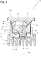
- FIG. 2 shows the in FIG. 1 illustrated lamp 10 in a sectional view.
- This sectional view shows that the reflector 20 forms a first reflection surface 25 and a second reflection surface 26.
- These Reflection surfaces 25/26 are web-shaped, wherein the first reflection surface 25 about a curvature axis (not shown) is curved.
- the axis of curvature of the first reflection surface 25 lies parallel to the apex axis 28.
- the second reflection surface 26 forms an inclined surface projecting from the apex axis 28.
- the apex axis 28 lies on the lamp central axis LM, which extends through the center of the lamp housing base surface and through the center of the cover 21.
- the light guide 15 extends into the reflector space 29 and is arranged with its longitudinal axis LA laterally offset from the light center axis LM.
- the light exit surface is inclined in the direction of offset downwards in the direction of board 12 and flat.
- the reflection surfaces 25 and 26 the light guide 15 is offset away from the first, curved reflection surface 25 in the direction of the second reflection surface 26.
- the first reflection surface 25 strikes the light guide 15 near the light entrance surface.
- the second reflection surface 26, strikes the light guide 25.
- the lowest point is in the direction of board 12 inclined light exit surface in the plane defined by the second reflection surface 26 plane. Due to this special design -the asymmetrically designed reflector 20 with its first, curved reflection surface 25 and its second, designed as an inclined surface reflection surface 26, the lateral offset of the light guide 15 to the lamp center axis LM and the inclined Light exit surface 16 - a special radiation characteristic of the household appliance lamp 10 is effected, which will be explained below.
- FIG. 3 shows one of the FIG. 2 borrowed representation in which the reflector 20 and cover glass 22 has been omitted for clarity of the facts explained below.
- dotted lines represent symbolically exemplary light rays emitted by the LED 13.
- D rays of light denoted by D emerge from the light exit surface 17 and are referred to as so-called direct light.
- This direct light D leaves the light exit surface 17 in a certain emission angle, which forms the opening angle of the light cone leaving the light exit surface 17.
- FIG. 3 shows that this scattered light S instead of in the direction of the not shown, the light exit opening of the lamp 10 covering glass pane 22 are thrown back in the direction of the lamp housing 14. They are thus not available for illuminating the domestic appliance interior and can be described as loss radiation.
- FIG. 3 It can also be seen that the cone axis K shown in dotted lines of the light cone leaving the light guide 15 is tilted in the tilting direction due to the inclination of the light exit surface 17 from the vertical. As a result, the light leaving the light guide 15 is directed substantially away from the light center axis LM or light guide longitudinal axis LA.
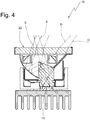
- FIG. 4 essentially corresponds FIG. 2 , where also dashed lines are shown here by way of example, which are for the LED 13 leaving light beams. Based on FIG. 4 can be explained very well the effect of the reflector.
- the scattered light rays S are taken from the first, curved reflection surface 25 and thrown in the direction of cover 21 and thus in the direction of the light exit opening of the lamp 10.
- the curvature of the reflection surface is dimensioned so that they throw the scattered light in the direction of offset of the light guide 15, ie substantially in the direction of the cone axis K.
- the first reflection surface 25 only receives the scattered light S for reflection, the direct light D emerging from the light guide 15 does not strike the first reflection surface 25 due to the arrangement of the light guide 15 within the reflection space 29.
- the second reflection surface 26 Due to its position and inclination to the light guide 15, the second reflection surface 26 is inoperative and thus does not reflect any light. This is insofar relevant to the overall radiation characteristic of the luminaire 10 as the second reflection surface 26, provided that it would perform a reflective function which reflected light against the cone axis K.
- the offset of the light guide 15 relative to the light center axis LM causes the direction in the first reflection surface 25 facing lateral surface maximizes and thus the utilization of the scattered light S is optimized taking into account the desired reflection direction to the cone axis K. That the light exit opening of the household appliance lamp 10 or the cover 21 leaving light forms a beam, which is also tilted in total in the offset direction of the light guide 15 and thus has a tendency.
- the luminaire according to the invention is installed in a domestic appliance, in particular a cooking appliance, that the first reflection surface 25 points away from an interior opening, so this scatters the scattered light rays S in the domestic appliance interior and thus the cone axis K of the light exit surface 17 leaving light cone in the domestic appliance interior is directed, a dazzling effect of a user is effectively avoided.
- the fastening arms 30, which engage in light guide grooves 31 and hold the light guide 15 in the luminaire housing 14, are arranged in a region of the light guide 15 in which no light rays impinge due to the given LED radiation angle. This ensures that the light guide of the light guide 15 is not adversely affected.
- FIG. 5 shows a household appliance in the form of a furnace 40.
- the oven comprises an outer housing wall 41 and an inside cooking chamber wall 42 which defines a cooking chamber 43.
- the cooking chamber 43 is accessible via an oven door 44, which is formed from an oven door frame 45 and an oven door glass 46, whereby through the furnace door glass 46 insight into the cooking chamber 43 can be taken.
- the cooking chamber wall 42 is provided with rails 47 which are arranged at different heights and carry food support 48 in the form of, for example, baking trays.
- domestic appliance lamps 10 according to the invention are mounted, the cooling bodies 11 of which are connected via recesses 50 of the housing wall 41 for heat release with the outside air.
- This oven is in FIG. 6 shown again in front view of the oven door 44.
- FIG. 7 the furnace 40 is cut along the section line BB in FIG FIG. 6 shown.
- the food support 48 which is seated on the rails 47.
- the Side walls are constructed bivalve and between the cooking chamber wall 42 and the housing wall 41, an insulating material 51 is arranged.
- the domestic appliance lamp 10 according to the invention is arranged, the heat sink 11 is directed towards the housing wall 41 and the cover 21 in the direction of cooking chamber 43.
- the cooking chamber rear wall 52 which delimits the cooking chamber towards the rear with respect to the oven door 44, is single-shelled in the present exemplary embodiment, but a two-shell structure is also suitable.
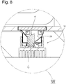
- FIG. 8 is an enlarged detail according to section circle VII in FIG. 7 .
- This detail enlargement shows the lamp arranged in cooking chamber wall 42 in detail.
- the first reflection surface 25 as well as the light exit surface 17 point in the direction of the cooking chamber rear wall 52 and throw the light emitted by the LED 13 into the cooking chamber 43 such that the predominant portion of the emitted radiation is directed away from the oven door 44.
- the direct light D as well as the scattered light S and directed toward cooking back wall 52
- Abstrahl characterizing the home appliance lights 10 a dazzling effect of the oven door glass 46 observing the cooking process user with optimal utilization of the emitted light to illuminate the oven 43 avoided.
- the invention provides a home appliance lamp 10, which by a combination of light guide 15, a provided with asymmetric reflection surfaces 25 and 26 reflector 20 and finally by an offset of the light guide 15 to the lamp center axis LM has a special emission characteristic that allows glare-free illumination of a domestic appliance interior ,
- the light output is by a desired Abstrahl characterizing supporting use of scattered radiation S of the light guide 15 significantly improved.
- the light guide 15 allows the spaced arrangement of the LED 13 from the domestic appliance interior, especially when it is a cooking chamber.
- the reflector 20 not only serves to reflect the scattered light radiation S but also to reflect the heat radiation emerging from a cooking chamber. In this way, the home appliance lamp 10 may be kept compact, so that it is also suitable for installation in home appliance side walls.
Landscapes
- Engineering & Computer Science (AREA)
- General Engineering & Computer Science (AREA)
- Physics & Mathematics (AREA)
- Chemical & Material Sciences (AREA)
- Combustion & Propulsion (AREA)
- Mechanical Engineering (AREA)
- Microelectronics & Electronic Packaging (AREA)
- Optics & Photonics (AREA)
- Electromagnetism (AREA)
- Non-Portable Lighting Devices Or Systems Thereof (AREA)
Description
- Die Erfindung betrifft eine Haushaltsgeräteleuchte für Gargeräte, wie Backöfen, Mikrowellengeräte oder Dampfgarer, mit einer LED als Lichtquelle, mit einem zur Anordnung an einer Gerätewandung vorgesehenen Leuchtengehäuse, mit einer Lichtaustrittsöffnung im Leuchtengehäuse, welche von einer lichtdurchlässigen Abdeckung verschlossen ist, mit einem Abstandselement, welches zwischen der LED und der Lichtaustrittsöffnung angeordnet ist und vor der Lichtaustrittsebene der LED sitzt, mit einem Reflektionsmittel, welche das von der LED emittierte Licht der Abdeckung zuleiten.
- Haushaltsgeräteleuchten sind aus dem Stand der Technik in vielfältiger Form bekannt. Sie dienen in der Regel zur Beleuchtung des Innenraumes eines Haushaltsgerätes bei dessen Betrieb bzw. beim Einblick eines Benutzers in einen solchen Aufnahmeraum.
- Gleich ob es Haushaltsgeräte zur Nahrungsmittelaufbewahrung (beispielsweise Kühlgeräte) oder Haushaltsgeräte zum Garen von Lebensmitteln (beispielsweise Backöfen) betrifft, werden bestimmte Anforderungen gestellt, die häufig schwer miteinander zu vereinen sind. Grundsätzlich soll die Ausleuchtung des Haushaltsgeräte-Innenraumes eine ausreichende visuelle Wahrnehmung der Nahrungsmittel durch den Benutzer ermöglichen, was häufig durch Abschattungen, beispielsweise durch Einlegeböden in Kühlschränken oder Bleche in Backöfen Probleme aufgrund von Verschattungen bereitet. Zudem soll die Beleuchtung den Benutzer grundsätzlich möglichst nicht blenden, wobei die hierfür einzusetzenden technischen Bauteile Lichtverluste mit sich bringen, die nachteilig sind.
- Der Einsatz von LEDs als Leuchtmittel hat zu neuen Möglichkeiten in der Beleuchtung von Haushaltsgeräten geführt, gleichzeitig stellt diese Technik die Konstrukteure vor neue Herausforderungen.
- Insbesondere bei Gargeräten für Nahrungsmittel, beispielsweise Backöfen oder Dampfgarer, sind große konstruktive Anstrengungen zu unternehmen, um eine Überhitzung der LEDs und eine damit einhergehende Schädigung zu vermeiden. Hierzu muss nicht nur die LEDeigene Wärme effektiv abgeführt werden. Es sind zudem Maßnahmen zu treffen, um die durch den Garvorgang auf die LED einwirkenden Temperaturbelastungen zu minimieren.
- Die
DE 10 2009 002 775 A1 soll als Beispiel für eine Gargeräteleuchte aus dem Stand der Technik dienen. In an sich üblicher Weise ist diese Leuchte in einem Gehäuseausschnitt über ein Leuchtengehäuse gehalten. Die Lichtaustrittsöffnung des Leuchtengehäuses ist mit einem lichtdurchlässigen Abdeckelement versehen, welches den Leuchteninnenraum primär vor Verschmutzung schützt, jedoch auch bereits eine erste Wärmebarriere darstellt. Das Leuchtengehäuse trägt an seinem dem Gargeräteinnenraum abgewandten Ende ein zylindrisches Abstandselement, wobei die Zylindermantelfläche von einem Reflektionsmaterial umgeben ist. Die Zylinderdeckflächen sind mit lichtdurchlässigen Deckelementen versehen. Dieser so gestaltete Zylinder dient einerseits dazu, die an seinem dem Garraum abgewandten Ende angeordnete LED möglichst weit vom Garraum zu beabstanden und durch diese erste Maßnahme die Wärmebelastung zu minimieren. Darüber hinaus bilden die Deckelemente weitere Temperaturbarrieren. Der Zylinder selbst dient darüber hinaus als Lichtschacht, um das von der LED emittierte Licht in Richtung Garraum zu führen. Schließlich wird als weitere Maßnahme die LED auf einen Kühlkörper montiert, so dass die Betriebswärme aber auch über die Wärmebarrieren zur LED gelangene Restwärme abgeführt werden kann. - Aus dem druckschriftlich nicht belegbaren Stand der Technik ist es darüber hinaus bekannt, den zwischen der LED und der Lichtaustrittsöffnung der Garrauminnenwand existierenden Hohlraum mit einem lichtdurchlässigen Isolationsmaterial zu versehen. So wird die dem Garraum entstammende Wärmestrahlung minimiert und die Ausleuchtung des Innenraumes ermöglicht.
- Im Stand der Technik vermindern die hier beschriebenen Maßnahmen zur Beabstandung der LED vom Garraum und zur Wärmeabschirmung die Lichtausbeute und die Ausleuchtungsqualität des Hausgeräteinnenraumes. Um die verminderte Lichtausbeute zu kompensieren können leistungsstärkere LEDs eingesetzt werden, wobei deren höhere Betriebstemperatur problematisch ist.
-
WO2009/141068 A1 oderEP 1598682 A2 nutzen Lichtleiter, um das Licht von einem Garraum entfernten Bereich in den Garraum hinein zu leiten. Die hierdurch hervorgerufene stark gerichtete Strahlung erfordert jedoch eine Vielzahl von Lichtaustrittsöffnungen und - je nach technischer Umsetzung - eine Vielzahl von Lichtquellen und Lichtleitern. Hinzukommt, dass die Vielzahl punktueller Lichtquellen in der Gehäuseinnenwand mit ihrer sehr hohen Helligkeit als unangenehm empfunden wird, so dass solche Lösungen aus Kosten- und Komfortgründen ungern umgesetzt werden. - Schließlich werden für eine optimale Ausleuchtung des Haushaltsgeräteinnenraumes, insbesondere bei Gargeräten gerne mehrere Leuchten in den Geräteseitenwänden zwischen den für Tragelemente vorgesehenen Ebenen angeordnet. So ist jeder Tragelementebene bei Backöfen beispielsweise jeder für ein Backblech vorgesehener Ebene eine Beleuchtung zugeordnet, so dass Abschattungen durch weitere Tragelemente die Ausleuchtungsqualität der jeweiligen Ebene nicht beeinträchtigen.
- Aufgrund genormter Außenmaße und dem Ziel, den nutzbaren Innenraum des Gargerätes möglichst groß zu halten, sind die hinter den seitlichen Innenwänden vorhandenen Bauräume ausgesprochen begrenzt. Dies erschwert die Konstruktion von Hausgeräteleuchten für Gargeräte unter der Nutzung von LEDs, da der dem Temperaturschutz dienende Abstand zwischen Garraum und LED begrenzt ist.
- Insofern lassen sich insbesondere bei der Positionierung einer Hausgeräteleuchte hinter der Seitenwand eines Garraumes die im Stand der Technik konstruktionsbedingten Lichtverluste nicht ohne weiteres durch leistungsfähigere LEDs ausgleichen, da diese in der Regel eine sehr viel höhere Betriebswärme produzieren.
- Die
US 2015/0009705 A1 zeigt eine sogenannte Retrofitlampe, die dem Ersatz herkömmlicher Entladungs- oder Glühlampen durch LED-Lampen dient. der Schwerpunkt der Offenbarung beschäftigt sich mit verschiedenen Lichtleitelementen, die das von einer LED emittierte Licht aufnehmen, die Wellenlänge des Lichts verändern und es gezielt wieder abgeben. - In der
US 2012/0147624 A1 ist ebenfalls eine sogenannte Retrofitlampe gezeigt, die für den Einsatz in Leuchten mit herkömmlichen Fassungen wie E27 vorgesehen sind. Eine im Lampensockel sitzende LED gibt ihr Licht an einen Lichtleiter ab, welcher das Licht in einen Reflektorraum hineinführt. Eine die Lichtaustrittsöffnung des Reflektorraumes abdeckende Streulinse ist unmittelbar oberhalb des Lichtleiterendes mit einer reflektierend wirkenden Linse versehen. In Folge dessen wird das den Lichteiter an seinem Ende verlassende Licht einer Totalreflektion in den Reflektorraum hinein unterworfen und gelangt erst durch die Reflektorwirkung aus der Lichtaustrittöffnung des Reflektors hinaus. -
US 2016/0047966 A1 zeigt eine Hausgeräteleuchte, bei welcher das von einer LED emittierte Licht von einem Reflektor gebündelt wird und anschließend über eine Linse an einen Lichtleiter eingespeist wird. Der Lichtleiter ist in einer Gerätewand eingelassen und mit Strukturen zur Lichtbrechung versehen. Über diese Strukturen wird das Licht aus dem Lichtleiter herausgelenkt, um einen Geräteinnenraum zu beleuchten. -
US 2016/0131818 A1 offenbart eine Beleuchtungseinrichtung für die Bodendüse eines Staubsaugers. Ein parallel zur Öffnungsebene von Lichtaustrittöffnungen geführter Lichtleiter ist mit lichtbrechenden Strukturen versehen, welche für einen Lichtaustritt aus den Lichtaustrittöffnungen sorgen. Eine LED speist Licht in den Lichtleiter ein. - In
US 6 350 041 B1 ist eine Lampe offenbart, die sich ebenfalls einer LED und eines Lichtleiters bedient. Das Lichtaustrittsende des Lichtleiters ist derart geformt, dass eine möglichst hohe Lichtstreuung erreicht wird. ein Großteil des das Lichtaustrittsende verlassenden Lichtes wird auf einen Reflektor geworfen und von diesem wiederum zur Lichtaustrittsöffnung eines Reflektorraumes geführt. - Schließlich zeigt
EP 2 428 737 A1 eine Leuchte zur Beleuchtung eines Kochfeldes. Als Lichtquelle wird eine Halogenlampe genutzt, welche geneigt in Relation zum Reflektor angeordnet ist. Die Neigung der Lampe hat einen sich asymmetrisch öffnenden Lichtkegel zur Folge. - Aufgabe der Erfindung ist es unter Nutzung einer LED, eine kompakt bauende Hausgeräteleuchte für Gargeräte bereit zu stellen, deren effektiv für die Innenraumausleuchtung nutzbare Lichtleistung maximiert ist. Gelöst wird die Erfindungsaufgabe von eine Hausgeräteleuchte mit den Merkmalen des Anspruchs 1, insbesondere mit dessen kennzeichnenden Merkmalen, wonach
- das Abstandelement ein materialeinheitlicher Lichtleiter ist, welcher das Licht aufnimmt und bündelt,
- die gesamte Lichtaustrittsfläche des Lichtleiters relativ zu einer Mittelachse des Lichtleiters mit einer einheitlichen Neigung versehen ist und so die Kegelachse des aus der Lichtaustrittsfläche austretende Lichtkegels ebenfalls relativ zur Mittelachse des Lichtleiters geneigt ist
- das Reflektionsmittel ein Reflektor ist, welcher einen Reflektorraum aufspannt,
- der Lichtleiter in den Reflektorraum hineingeführt ist
- der Reflektor im Wesentlichen die aus dem Lichtleiter austretende Streustrahlung in Richtung Abdeckung lenkt.
- Der wesentliche Vorteil der erfindungsgemäßen Haushaltsgeräteleuchte ist darin zu sehen, dass zwei unterschiedliche, lichtbeeinflussende Bauteile zur Maximierung der Lichtausbeute genutzt werden. Mittels des materialeinheitlichen Lichtleiters, beispielsweise eines aus Kunststoff oder Glas bestehenden Lichtleitstabes, also einem aus Vollmaterial bestehenden Lichtleiter, wird das Licht der LED aufgenommen, gebündelt und mit geringstmöglichen Streuverlusten nahe an die Lichtaustrittsöffnung des Leuchtengehäuses, also nahe an die Innenwand des Hausgeräteinnenraumes herangeführt. Dabei befindet sich der Lichtleiter zumindest Abschnittsweise im Reflektorraum, so dass die aus dem Lichtleiter austretende Streustrahlung aufgenommen und ebenfalls in Richtung Lichtaustrittsöffnung des Leuchtengehäuses, also in Richtung Hausgeräteinnenraum gelenkt wird. Gleichzeitig ermöglicht der Lichtleiter eine weitest mögliche Beabstandung der LED vom Hausgeräteinnenraum und dient der Wärmeabschirmung. Ebenfalls der Wärmeabschirmung dient der Reflektor, welcher nicht nur das Streulicht, sondern auch aus dem Geräteinnenraum eintretende Wärmestrahlung reflektiert.
- Um eine blendfreie Ausleuchtung des Geräteinnenraumes zu erzeugen, ist die Lichtaustrittsfläche des Lichtleiters relativ zu einer Mittelachse des Lichtleiters geneigt. In Folge dessen ist die Kegelachse des aus der Lichtaustrittsfläche austretende Lichtkegels ebenfalls relativ zur Mittelachse des Lichtleiters geneigt, wobei in der Anwendung die Lichtaustrittsfläche vom Benutzer weg weist, also in Richtung beispielsweise der Garraumrückwand geneigt ist. Durch die geneigte Lichtaustrittsfläche wird der austretende Lichtkegel in den Geräteinnenraum hineingeschwenkt, was sich durch eine entsprechende Neigung der Kegelachse - welche der Kegelspitze entspringt und durch das Zentrum des Kegelbodens verläuft - ausdrückt. Der Kegelmantel des austretenden Lichtkegels wird durch den Abstrahlwinkel (gleich Halbwertswinkel) der Lichtaustrittsfläche bestimmt.
- Der Reflektor dient im Wesentlichen dazu, dass sonst als Verluststrahlung geltende, nicht im Hausgeräteinnenraum ankommende Streulicht einzufangen, welches unvermeidlich aus der Mantelfläche des Lichtleiters austritt.
- Vorgesehen ist weiterhin, dass der Reflektor das Streulicht weit überwiegend in Richtung der Kegelachse des aus der Lichtaustrittsfläche des Lichtleiters austretenden Lichtkegels lenkt, damit auch eine durch das reflektierte Streulicht hervorgerufene Blendwirkung des Benutzer weitestgehend vermieden wird.
- Es ist vorgesehen, dass der Reflektor zwei einer Scheitelachse entspringende, bahnförmige Reflektionsflächen aufweist, wobei die Scheitelachse nahe einer Lichteintrittsfläche des Lichtleiters angeordnet ist. Diese Anordnung nahe der Lichteintrittsfläche des Lichtleiters stellt sicher, dass das prinzipbedingt aus dem Lichtleiter austretende Streulicht vom Reflektor aufgefangen wird.
- Insbesondere ist vorgesehen, dass die erste, bahnförmige Reflektionsfläche um eine zur Scheitelachse parallele Krümmungsachse gekrümmt ist, wobei vorgesehen sein kann, dass der lichteintrittsflächennahe Bereich unterhalb einer Ebene liegt, in der die Randstrahlen des durch den Abstrahlwinkel der LED definierten Strahlenkegels auf die Grenzflächen des Lichtleitermantels treffen.
- Hierdurch ist gewährleistet, dass ein Maximum des Streulichts aufgefangen und in Richtung Hausgeräteinnenraum reflektiert wird.
- Vorgesehen ist weiterhin, dass der Lichtleiter zur Scheitelachse der Reflektionsflächen seitlich versetzt ist, wobei zusätzlich vorgesehen sein kann, dass die geneigte Lichtaustrittsfläche des Lichtleiters in Richtung des seitlichen Versatzes abfällt. Vorgesehen ist weiterhin, dass die zweite bahnförmige Reflektionsfläche ungekrümmt, insbesondere plan ist und an den lichteintrittsflächennahen Übergangsbereich von Lichtaustrittsfläche und Lichtleitermantelfläche geführt ist, wobei die Neigung der zweiten Reflektionsfläche in Bezug auf die Kegelachse des aus der Lichtaustrittfläche austretenden Lichtkegels im Wesentlichen zur Wirkungslosigkeit der zweiten Reflektionsfläche führt.
- Der Versatz des Lichtleiters zur Scheitelachse, insbesondere ein Versatz von der ersten Reflektionsfläche weg bewirkt eine stärkere Streulichtausbeute durch die erste Reflektionsfläche. Bei der oben angesprochenen entsprechenden Neigung der Lichtaustrittsfläche wird das aus der Lichtaustrittsfläche austretende Direktlicht wie auch das vom Reflektor zurückgeworfene Streulicht in etwa Richtungsgleich in den Hausgeräteinnenraum geführt.
- Es ist weiterhin vorgesehen, dass die zweite bahnförmige Reflektionsfläche ungekrümmt ist und an den lichteintrittsflächennahen Übergangsbereich von Lichtaustrittsfläche und Lichtleitermantelfläche geführt ist, wobei die Neigung der zweiten Reflektionsfläche in Bezug auf die Kegelachse des aus der Lichtaustrittfläche austretenden Lichtkegels im Wesentlichen zur Wirkungslosigkeit der zweiten Reflektionsfläche führt.
- Auf diese Weise ist bei entsprechender Einbaulage der Leuchte gewährleistet, dass das Licht ausschließlich im Wesentlichen in Richtung der Hausgeräterückwand, insbesondere der Garraumrückwand eines Gargerätes geführt ist.
- Ferner ist vorgesehen, dass der Reflektor und die Eintauchtiefe des Lichtleiters in den Reflektorraum derart aufeinander abgestimmt sind, dass der Reflektor lediglich die aus dem Lichtleiter austretende Streustrahlung, nicht jedoch aus der Lichtaustrittsfläche austretende Direktstrahlung reflektiert.
- Weitere Vorteile so wie ein besseres Verständnis der Erfindung folgen aus der Beschreibung eines Ausführungsbeispiels. Es zeigen:
- Figur 1
- die Explosionsansicht einer erfindungsgemäßen Leuchte,
- Figur 2
- eine Schnittansicht der Leuchte gemäß
Figur 1 , - Figur 3
- eine schematische Darstellung der Abstrahlcharakteristik der Leuchte gemäß
Figur 1 ohne den erfindungsgemäßen Reflektor an Hand einer Schnittdarstellung, - Figur 4
- eine schematische Darstellung der Abstrahlcharakteristik der Leuchte gemäß
Figur 1 unter Berücksichtigung des erfindungsgemäßen Reflektors, - Figur 5
- ein Ofen mit erfindungsgemäßer Hausgeräteleuchte in perspektivischer Ansicht,
- Figur 6
- der Ofen gemäß
Figur 5 in Ansicht von vorne, - Figur 7
- eine Schnittdarstellung des Ofens gemäß Schnittlinie B-B in
Figur 6 , - Figur 8
- eine Ausschnittvergrößerung gemäß Ausschnittskreis VII in
Fig. 7 . - In den Figuren ist eine Hausgeräteleuchte, auch einfach nur Leuchte genannt, insgesamt mit der Bezugsziffer 10 versehen. Die Hausgeräteleuchte umfasst, wie aus
Figur 1 zu erkennen ist, zunächst einen Kühlkörper 11, auf welchem eine Platine 12 mit aufgesetzter LED 13 (Figur 2 ) platziert ist. - Auf dem Kühlkörper ist weiterhin ein Leuchtengehäuse 14 aus einem elektrisch und thermisch isolierenden Material, wie beispielsweise Kunststoff oder Keramik, angeordnet, innerhalb dessen ein Lichtleiter 15 gehalten wird. Im vorliegenden Ausführungsbeispiel handelt es sich um einen stabförmigen Lichtleiter aus Glas. Dieser verfügt über eine LEDnahe Lichteintrittsfläche 16 (
Figur 2 ) sowie eine LED-ferne Lichtaustrittsfläche 17. Die Lichtaustrittsfläche 17 ist hinsichtlich einer Mittelachse des Lichtleiters 15 geneigt. In Bezug auf die Platine 12 weist sie eine nach unten, zur Platine 12 weisende Neigung auf. Im Übrigen ist die Lichtaustrittsfläche eben gehalten. - Das Leuchtengehäuse 14 verfügt über Rastausnehmungen 18, mittels derer ein Rastfeder 19 aufweisender Reflektor 20 am Leuchtengehäuse 14 verankerbar ist. Der Reflektor 20 seinerseits bildet eine nicht näher bezeichnete Lichtaustrittsöffnung der Leuchte 10, welche durch ein lichtdurchlässiges Abdeckelement 21, im Ausführungsbeispiel eine Glasscheibe 22, verschlossen ist. Schließlich verfügt der Reflektor 20 über Rastelemente R, mit welchen er in einem Ausschnitt einer Gerätewand festgelegt wird.
- Zur Leuchte gehört im Ausführungsbeispiel darüber hinaus Anschlussleiter 23, die mit ihren ersten Enden in nicht dargestellter Weise Leiterbahnen der Platine 12 kontaktieren und deren der Platine 12 abgewandte Enden einen Steckverbinder 24 zum Anschluss an die Spannungsversorgung tragen.
-
Figur 2 zeigt die inFigur 1 dargestellte Leuchte 10 in einer Schnittansicht. Dieser Schnittansicht ist zu entnehmen, dass der Reflektor 20 eine erste Reflektionsfläche 25 und eine zweite Reflektionsfläche 26 ausbildet. Diese Reflektionsflächen 25/26 bilden, gemeinsam mit den Reflektorseitenwänden 27 den Reflektorraum 29 und entspringen einer gemeinsamen Scheitelachse 28. Die Reflektionsflächen 25/26 sind bahnartig geformt, wobei die erste Reflektionsfläche 25 um eine Krümmungsachse (nicht dargestellt) gekrümmt ist. Die Krümmungsachse der ersten Reflektionsfläche 25 liegt parallel zur Scheitelachse 28. Die zweite Reflektionsfläche 26 bildet eine, der Scheitelachse 28 entspringende Schrägfläche. Die Scheitelachse 28 liegt auf der Leuchtenmittelachse LM, die sich durch das Zentrum der Leuchtengehäusebodenfläche und durch das Zentrum des Abdeckelementes 21 sich erstreckt. - Der Lichtleiter 15 erstreckt sich in den Reflektorraum 29 hinein und ist mit seiner Längsachse LA seitlich versetzt zur Leuchtenmittelachse LM angeordnet. Die Lichtaustrittsfläche ist in Versatzrichtung nach unten in Richtung Platine 12 geneigt und plan ausgebildet. Hinsichtlich der Reflektionsflächen 25 und 26 ist der Lichtleiter 15 von der ersten, gekrümmten Reflektionsfläche 25 weg in Richtung zweiter Reflektionsfläche 26 versetzt.
- In Folge dieses Versatzes und der Krümmung der ersten Reflektionsfläche 25 sowie der Ausbildung der zweiten Reflektionsfläche 26 als Schrägfläche trifft die erste Reflektionsfläche 25 lichteintrittsflächennah auf den Lichtleiter 15. Die zweite Reflektionsfläche 26 hingegen trifft lichteintrittsflächenfern auf den Lichtleiter 25. Im Idealfall liegt der tiefste Punkt der in Richtung Platine 12 geneigten Lichtaustrittsfläche in der von der zweiten Reflektionsfläche 26 aufgespannten Ebene. Durch diese spezielle Ausbildung -den asymmetrisch ausgebildete Reflektor 20 mit seiner ersten, gekrümmten Reflektionsfläche 25 und seiner zweiten, als Schrägfläche ausgebildeten Reflektionsfläche 26 dem seitlichen Versatz des Lichtleiters 15 zur Leuchtenmittelachse LM und der geneigten Lichtaustrittsfläche 16 - wird eine spezielle Abstrahlcharakteristik der Hausgeräteleuchte 10 bewirkt, welche im Folgenden erläutert wird.
-
Figur 3 zeigt eine derFigur 2 entlehnte Darstellung, bei welcher zur Verdeutlichung der nachfolgend erläuterten Sachverhalte der Reflektor 20 samt Abdeckglas 22 weggelassen wurde. Die inFigur 3 gezeigten strichpunktierten Linien stellen symbolisch exemplarische Lichtstrahlen dar, die von der LED 13 emittiert werden. Zunächst sind inFigur 3 mit D bezeichnete Lichtstrahlen gezeigt, die aus der Lichtaustrittsfläche 17 austreten und als sogenanntes Direktlicht bezeichnet werden. Dieses Direktlicht D verlässt die Lichtaustrittsfläche 17 in einem bestimmten Abstrahlwinkel, der den Öffnungswinkel des die Lichtaustrittsfläche 17 verlassenden Lichtkegels bildet. - Dargestellt sind weiterhin exemplarische Lichtstrahlen S, welche aufgrund ihres Einfallswinkels an der Lichtaustrittsfläche 17 reflektiert, in den Lichtleiter 15 zurückgeworfen werden und aus dessen Mantelfläche austreten. Diese mit S bezeichneten Lichtstrahlen stellen das sogenannte Streulicht dar.
Figur 3 zeigt, dass dieses Streulicht S statt in Richtung der nicht eingezeichneten, die Lichtaustrittsöffnung der Leuchte 10 abdeckenden Glasscheibe 22 zurück in Richtung des Leuchtengehäuses 14 geworfen werden. Sie stehen somit nicht zur Ausleuchtung des Hausgeräteinnenraumes zur Verfügung und können durchaus als Verluststrahlung bezeichnet werden. - In
Figur 3 ist auch ersichtlich, dass die punktiert dargestellte Kegelachse K des den Lichtleiter 15 verlassenden Lichtkegels aufgrund der Neigung der Lichtaustrittsfläche 17 von der Vertikalen in Neigungsrichtung verkippt ist. In Folge dessen wird das den Lichtleiter 15 verlassende Licht im Wesentlichen von Leuchtenmittelachse LM bzw. Lichtleiterlängsachse LA weg gerichtet. -
Figur 4 entspricht im WesentlichenFigur 2 , wobei auch hier exemplarisch strichpunktierte Linien eingezeichnet sind, die für die LED 13 verlassenden Lichtstrahlen stehen. An Hand vonFigur 4 kann sehr gut die Wirkung des Reflektors erläutert werden. - Wie
Figur 4 zu entnehmen ist, werden die Streulichtstrahlen S von der ersten, gekrümmten Reflektionsfläche 25 aufgenommen und in Richtung Abdeckelement 21 und somit in Richtung Lichtaustrittsöffnung der Leuchte 10 geworfen. Die Krümmung der Reflektionsfläche ist so bemessen, dass sie das Streulicht in Versatzrichtung des Lichtleiters 15, also im Wesentlichen in Richtung der Kegelachse K werfen. Dabei nimmt die erste Reflektionsfläche 25 lediglich das Streulicht S zur Reflektion auf, das aus dem Lichtleiter 15 austretende Direktlicht D trifft aufgrund der Anordnung des Lichtleiters 15 innerhalb des Reflektionsraumes 29 nicht auf die erste Reflektionsfläche 25. - Die zweite Reflektionsfläche 26 ist aufgrund ihrer Lage und Neigung zum Lichtleiter 15 funktionslos und reflektiert somit kein Licht. Dies ist insofern für die Gesamtabstrahlcharakteristik der Leuchte 10 relevant als die zweite Reflektionsfläche 26, sofern sie eine reflektierende Funktion ausfüllen würde das Licht gegen die Kegelachse K reflektierte.
- Wie aus
Figur 4 schließlich auch ersichtlich ist, führt der Versatz des Lichtleiters 15 relativ zur Leuchtenmittelachse LM dazu, dass die in Richtung erste Reflektionsfläche 25 weisende Mantelfläche maximiert und somit die Ausnutzung des Streulichtes S unter Berücksichtigung der gewünschten Reflektionsrichtung zur Kegelachse K optimiert wird. Dass die Lichtaustrittsöffnung der Hausgeräteleuchte 10 bzw. das Abdeckelement 21 verlassende Licht bildet ein Strahlenbündel, welches ebenfalls insgesamt in Versatzrichtung des Lichtleiters 15 verkippt ist und somit eine Neigung aufweist. - Wenn nun die erfindungsgemäße Leuchte derart in ein Hausgerät, insbesondere ein Gargerät eingebaut wird, dass die erste Reflektionsfläche 25 von einer Innenraumöffnung wegweist, diese also die Streulichtstrahlen S in den Hausgeräteinnenraum hineinrichtet und somit auch die Kegelachse K des die Lichtaustrittsfläche 17 verlassenden Lichtkegels in den Hausgeräteinnenraum hineingerichtet ist, wird eine Blendwirkung eines Benutzers wirksam vermieden.
- Um die Lichtausbeute der Hausgeräteleuchte 10 weiter zu optimieren, sind die Befestigungsarme 30, welche in Lichtleiternuten 31 eingreifen und den Lichtleiter 15 im Leuchtengehäuse 14 halten in einem Bereich des Lichtleiters 15 angeordnet, in welchem aufgrund des gegebenen LED-Abstrahlwinkels keine Lichtstrahlen auftreffen. Hierdurch ist sichergestellt, dass die Lichtführung des Lichtleiters 15 nicht nachteilig beeinflusst wird.
-
Figur 5 zeigt ein Hausgerät in Form eines Ofens 40. Der Ofen umfasst eine äußere Gehäusewand 41 und eine innen gelegene Garraumwand 42, welche einen Garraum 43 umgrenzt. Der Garraum 43 ist über eine Ofentür 44 zugänglich, welche aus einem Ofentürrahmen 45 sowie einem Ofentürglas 46 gebildet ist, wobei durch das Ofentürglas 46 Einsicht in den Garraum 43 genommen werden kann. Die Garraumwand 42 ist mit Schienen 47 versehen, die in unterschiedlichen Höhen angeordnet sind und Gargutträger 48 in Form von beispielsweise Backblechen tragen. Innerhalb von Ausschnitten 49 der Garraumwand sind erfindungsgemäße Hausgeräteleuchten 10 montiert, deren Kühlkörper 11 über Ausnehmungen 50 der Gehäusewand 41 zur Wärmeabgabe mit der Außenluft in Verbindung stehen. Dieser Ofen ist inFigur 6 nochmals in Ansicht von vorne auf die Ofentür 44 gezeigt. - In
Figur 7 ist der Ofen 40 geschnitten entlang der Schnittlinie B-B inFigur 6 dargestellt. Man sieht insofern in Aufsicht auf den Gargutträger 48, welcher auf den Schienen 47 aufsitzt. Deutlich zu sehen ist auch, dass die Seitenwände zweischalig aufgebaut sind und zwischen der Garraumwand 42 und der Gehäusewand 41 ein Isoliermaterial 51 angeordnet ist. Innerhalb einer Aussparung im Isoliermaterial 51 ist die erfindungsgemäße Hausgeräteleuchte 10 angeordnet, deren Kühlkörper 11 in Richtung Gehäusewand 41 und deren Abdeckelement 21 in Richtung Garraum 43 gerichtet ist. Die Garraumrückwand 52, welche gegenüber der Ofentür 44 den Garraum nach hinten begrenzt, ist im vorliegenden Ausführungsbeispiel einschalig, ein zweischaliger Aufbau kommt jedoch ebenso in Frage. -
Figur 8 ist eine Ausschnittsvergrößerung gemäß Ausschnittskreis VII inFigur 7 . - Diese Ausschnittsvergrößerung zeigt die in Garraumwand 42 angeordnete Leuchte im Detail. Die erste Reflektionsfläche 25 wie auch die Lichtaustrittsfläche 17 weisen in Richtung Garraumrückwand 52 und werfen das von der LED13 emittierte Licht derart in den Garraum 43 hinein, dass der überwiegende Anteil der emittierten Strahlung von der Ofentür 44 weggerichtet ist. Auf diese Weise wird mit durch Nutzung des Direktlichtes D wie auch des Streulichtes S und der in Richtung Garrückwand 52 gerichteten Abstrahlcharakteristik der Hausgeräteleuchten 10 eine Blendwirkung des durch das Ofentürglas 46 den Garvorgang beobachtenden Benutzers bei optimaler Ausnutzung des emittierten Lichtes zur Erleuchtung des Garraumes 43 vermieden.
- Zusammenfassend stellt die Erfindung eine Hausgeräteleuchte 10 vor, welche durch eine Kombination von Lichtleiter 15, einen mit asymmetrischen Reflektionsflächen 25 und 26 versehenen Reflektor 20 und schließlich durch einen Versatz des Lichtleiters 15 zur Leuchtenmittelachse LM eine spezielle Abstrahlcharakteristik aufweist, die eine blendfreie Ausleuchtung eines Hausgeräteinnenraumes ermöglicht. Zudem wird die Lichtausbeute durch einen die gewünschte Abstrahlcharakteristik unterstützende Nutzung der Streustrahlung S des Lichtleiters 15 wesentlich verbessert. Der Lichtleiter 15 erlaubt die beabstandete Anordnung der LED 13 vom Hausgeräteinnenraum, insbesondere wenn sich um einen Garraum handelt. Der Reflektor 20 dient darüber hinaus nicht nur zur Reflektion der Streulichtstrahlung S sondern auch zur Reflektion der aus einem Garraum austretenden Wärmestrahlung. Auf diese Weise kann die Hausgeräteleuchte 10 kompakt gehalten sein, so dass sie sich auch für den Einbau in Hausgeräteseitenwänden eignet.
-
- 10
- Hausgeräteleuchte
- 11
- Kühlkörper
- 12
- Platine
- 13
- LED
- 14
- Leuchtengehäuse
- 15
- Lichtleiter
- 16
- Lichteintrittsfläche
- 17
- Lichtaustrittsfläche
- 18
- Rastausnehmung
- 19
- Rastfeder
- 20
- Reflektor
- 21
- Abdeckelement
- 22
- Glasscheibe
- 23
- Anschlussleiter
- 24
- Steckverbinder
- 25
- erste Reflektionsfläche
- 26
- zweite Reflektionsfläche
- 27
- Reflektorseitenwand
- 28
- Scheitelachse
- 29
- Reflektorraum
- 30
- Befestigungsarme
- 31
- Lichtleiternuten
- 40
- Ofen
- 41
- äußere Gehäusewand
- 42
- Garraumwand
- 43
- Garraum
- 44
- Ofentür
- 45
- Ofentürrahmen
- 46
- Ofentürglas
- 47
- Schiene
- 48
- Gargutträger
- 49
- Ausschnitt
- 50
- Ausnehmung
- 51
- Isoliermaterial
- 52
- Garraumrückwand
- K
- Kegelachse
- R
- Rastelement
- S
- Streulicht
- D
- Direktlicht
- LM
- Leuchtenmittelachse
- LA
- Längsachse von 15
Claims (10)
- Haushaltsgeräteleuchte (10) für Gargeräte, wie Backöfen, Mikrowellengeräte oder Dampfgarer,- mit einer LED (13) als Lichtquelle,- mit einem zur Anordnung an einer Gerätewandung vorgesehenen Leuchtengehäuse (14),- mit einer Lichtaustrittsöffnung (17) im Leuchtengehäuse (14) welche von einer lichtdurchlässigen Abdeckung (21) verschlossen ist,- mit einem Abstandselement, welches zwischen der LED (13) und der Lichtaustrittsöffnung (17) angeordnet ist und vor der Lichtaustrittsebene der LED (13) sitzt,- mit einem Reflektionsmittel, welche das von der LED (13) emittierte Licht der Abdeckung (21) zuleitet,dadurch gekennzeichnet, dass- das Abstandelement ein materialeinheitlicher Lichtleiter (15) ist, welcher das Licht aufnimmt und bündelt,- die gesamte Lichtaustrittsfläche (17) des Lichtleiters (15) relativ zu einer Mittelachse (LA) des Lichtleiters (15) mit einer einheitlichen Neigung versehen ist und so die Kegelachse (K) des aus der Lichtaustrittsfläche (17) austretende Lichtkegels ebenfalls relativ zur Mittelachse (LA) des Lichtleiters (15) geneigt ist,- das Reflektionsmittel ein Reflektor (20) ist, welcher einen Reflektorraum (29) aufspannt,- der Lichtleiter (15) in den Reflektorraum (29) hineingeführt ist,- der Reflektor (20) im Wesentlichen die aus dem Lichtleiter (15) austretende Streustrahlung (S) in Richtung Abdeckung (21) lenkt.
- Haushaltsgeräteleuchte nach Anspruch 1, dadurch gekennzeichnet, dass der Reflektor (20) das Licht weit überwiegend Richtung der Kegelachse (K) des aus der Lichtaustrittsfläche (17) des Lichtleiters (15) austretenden Lichtkegels lenkt.
- Haushaltsgeräteleuchte nach einem der vorhergehenden Ansprüche, dadurch gekennzeichnet, dass der Reflektor (20) zwei einer Scheitelachse (28) entspringende, bahnförmige Reflektionsflächen (25/26) aufweist, wobei die Scheitelachse (28) nahe einer Lichteintrittsfläche (16) des Lichtleiters (15) angeordnet ist.
- Haushaltsgeräteleuchte nach Anspruch 3, dadurch gekennzeichnet, dass die erste, bahnförmige Reflektionsfläche (25) um eine zur Scheitelachse (28) parallele Krümmungsachse gekrümmt ist.
- Haushaltsgeräteleuchte nach Anspruch 4, dadurch gekennzeichnet, dass die erste, gekrümmte Reflektionsfläche (25) bis in einen lichteintrittsflächennahen Bereich des Lichtleiters (15) geführt ist.
- Haushaltsgeräteleuchte nach Anspruch 5, dadurch gekennzeichnet, dass der lichteintrittsflächennahe Bereich unterhalb einer Ebene liegt, in der die Randstrahlen des durch den Abstrahlwinkel der LED (13) definierten Strahlenkegels auf die Grenzflächen des Lichtleitermantels treffen.
- Haushaltgeräteleuchte nach Anspruch 4, dadurch gekennzeichnet, dass der Lichtleiter (15) zur Scheitelachse (28) der bahnförmigen Reflektionsflächen (25/26) seitlich versetzt ist.
- Haushaltsgeräteleuchte nach Anspruch 7 und 1, dadurch gekennzeichnet, dass die geneigte Lichtaustrittsfläche (17) des Lichtleiters (15) in Richtung des seitlichen Versatzes abfällt.
- Haushaltsgeräteleuchte nach Anspruch 8 und 4, dadurch gekennzeichnet, dass die zweite bahnförmige Reflektionsfläche (26) ungekrümmt ist und an den lichteintrittsflächennahen Übergangsbereich von Lichtaustrittsfläche (17) und Lichtleitermantelfläche geführt ist, wobei die Neigung der zweiten Reflektionsfläche (26) in Bezug auf die Kegelachse (K) des aus der Lichtaustrittfläche (17) austretenden Lichtkegels im Wesentlichen zur Wirkungslosigkeit der zweiten Reflektionsfläche (26) führt.
- Haushaltsgeräteleuchte nach einem der vorhergehenden Ansprüche, dadurch gekennzeichnet, dass der Reflektor (20) und die Eintauchtiefe des Lichtleiters (15) in den Reflektorraum (29) derart aufeinander abgestimmt sind, dass der Reflektor (20) lediglich die aus dem Lichtleiter (15) austretende Streustrahlung (S), nicht jedoch aus der Lichtaustrittsfläche (17) austretende Direktstrahlung (D) reflektiert.
Applications Claiming Priority (2)
| Application Number | Priority Date | Filing Date | Title |
|---|---|---|---|
| DE202016104855.9U DE202016104855U1 (de) | 2016-09-02 | 2016-09-02 | Haushaltsgeräteleuchte |
| DE102016118041 | 2016-09-23 |
Publications (2)
| Publication Number | Publication Date |
|---|---|
| EP3290810A1 EP3290810A1 (de) | 2018-03-07 |
| EP3290810B1 true EP3290810B1 (de) | 2018-09-19 |
Family
ID=59677141
Family Applications (1)
| Application Number | Title | Priority Date | Filing Date |
|---|---|---|---|
| EP17187080.1A Active EP3290810B1 (de) | 2016-09-02 | 2017-08-21 | Haushaltegeräteleuchte |
Country Status (2)
| Country | Link |
|---|---|
| US (1) | US10151495B2 (de) |
| EP (1) | EP3290810B1 (de) |
Families Citing this family (5)
| Publication number | Priority date | Publication date | Assignee | Title |
|---|---|---|---|---|
| DE202019106170U1 (de) * | 2019-11-06 | 2019-11-22 | Bjb Gmbh & Co. Kg | Schwenkbare Beleuchtungseinrichtung |
| DE102021101700B3 (de) * | 2021-01-26 | 2022-07-07 | Bjb Gmbh & Co. Kg | Mikrowellengargerät mit adaptierter LED-Leuchte |
| US12372251B2 (en) | 2021-10-29 | 2025-07-29 | Whirlpool Corporation | Lighting assembly for a cooking appliance |
| WO2026047386A1 (en) * | 2024-09-02 | 2026-03-05 | Gorenje, d.o.o. | Cooking appliance comprising an imaging device |
| CN121512348A (zh) * | 2026-01-15 | 2026-02-13 | 美的集团股份有限公司 | 烹饪设备 |
Citations (1)
| Publication number | Priority date | Publication date | Assignee | Title |
|---|---|---|---|---|
| DE102009002775A1 (de) * | 2009-04-30 | 2010-11-04 | BSH Bosch und Siemens Hausgeräte GmbH | Lampe für Hausgerät sowie Hausgerät, insbesondere zum Zubereiten von Lebensmitteln, mit einer Lampe |
Family Cites Families (27)
| Publication number | Priority date | Publication date | Assignee | Title |
|---|---|---|---|---|
| JP2527274B2 (ja) * | 1990-11-19 | 1996-08-21 | 株式会社小糸製作所 | 自動車用ヘッドランプ |
| US5278731A (en) * | 1992-09-10 | 1994-01-11 | General Electric Company | Fiber optic lighting system using conventional headlamp structures |
| US6350041B1 (en) * | 1999-12-03 | 2002-02-26 | Cree Lighting Company | High output radial dispersing lamp using a solid state light source |
| US6481130B1 (en) * | 2000-08-11 | 2002-11-19 | Leotek Electronics Corporation | Light emitting diode linear array with lens stripe for illuminated signs |
| JP4049260B2 (ja) * | 2003-03-11 | 2008-02-20 | 株式会社小糸製作所 | 車両用灯具 |
| JP4047266B2 (ja) * | 2003-11-19 | 2008-02-13 | 株式会社小糸製作所 | 灯具 |
| JP4300123B2 (ja) * | 2004-01-13 | 2009-07-22 | スタンレー電気株式会社 | 導光体を用いたled灯具 |
| US6971781B2 (en) | 2004-03-18 | 2005-12-06 | The Boeing Company | Remote source lighting |
| EP1598682A2 (de) | 2004-05-19 | 2005-11-23 | Schott AG | Faseroptische Vorrichtung zur Innenbeleuchtung von Küchen und Hausgeräten |
| US6991355B1 (en) * | 2004-06-16 | 2006-01-31 | Osram Sylvania Inc. | light emitting diode lamp with light pipes |
| EP2119967B1 (de) | 2008-05-17 | 2015-07-01 | Electrolux Home Products Corporation N.V. | Garofen mit einer Beleuchtung für eine Muffel und Verfahren zur Beleuchtung einer Ofenmuffel |
| JP2011126262A (ja) | 2009-04-09 | 2011-06-30 | Teijin Ltd | 熱伝導性樹脂複合成形体、led照明装置 |
| JP4991834B2 (ja) * | 2009-12-17 | 2012-08-01 | シャープ株式会社 | 車両用前照灯 |
| US8733996B2 (en) * | 2010-05-17 | 2014-05-27 | Sharp Kabushiki Kaisha | Light emitting device, illuminating device, and vehicle headlamp |
| US8807799B2 (en) * | 2010-06-11 | 2014-08-19 | Intematix Corporation | LED-based lamps |
| DE102010040509A1 (de) * | 2010-09-09 | 2012-03-15 | BSH Bosch und Siemens Hausgeräte GmbH | Dunstabzugshaube |
| WO2012036541A1 (en) * | 2010-09-17 | 2012-03-22 | Invisua B.V. | Led lighting system comprising an optical system suitable for providing a light beam |
| JP5528983B2 (ja) | 2010-10-15 | 2014-06-25 | 株式会社エス・ケー・ジー | 照明装置 |
| JP5658600B2 (ja) * | 2011-03-07 | 2015-01-28 | スタンレー電気株式会社 | 発光装置 |
| JP6138420B2 (ja) * | 2012-04-06 | 2017-05-31 | シャープ株式会社 | 発光装置および車両用前照灯 |
| CN105121947B (zh) | 2013-02-01 | 2016-12-14 | 夸克星有限责任公司 | 包括多个发光元件的照明装置 |
| WO2014124285A2 (en) * | 2013-02-08 | 2014-08-14 | Quarkstar Llc | Illumination device providing direct and indirect illumination |
| DE102013005988A1 (de) * | 2013-04-08 | 2014-10-09 | Emz-Hanauer Gmbh & Co. Kgaa | Elektrisches Haushaltsgerät mit beleuchtetem Innenraum |
| JP2015011976A (ja) * | 2013-07-02 | 2015-01-19 | 東芝ライテック株式会社 | 発光装置および照明装置 |
| DE102014102355A1 (de) | 2014-02-24 | 2015-08-27 | Hella Kgaa Hueck & Co. | Beleuchtungsvorrichtung für Fahrzeuge |
| JP6689000B2 (ja) * | 2014-11-10 | 2020-04-28 | パナソニックIpマネジメント株式会社 | 掃除機用照明装置 |
| CN106322230A (zh) * | 2015-06-30 | 2017-01-11 | 中华映管股份有限公司 | 背光模块及液晶显示器 |
-
2017
- 2017-08-21 EP EP17187080.1A patent/EP3290810B1/de active Active
- 2017-09-02 US US15/694,779 patent/US10151495B2/en active Active
Patent Citations (1)
| Publication number | Priority date | Publication date | Assignee | Title |
|---|---|---|---|---|
| DE102009002775A1 (de) * | 2009-04-30 | 2010-11-04 | BSH Bosch und Siemens Hausgeräte GmbH | Lampe für Hausgerät sowie Hausgerät, insbesondere zum Zubereiten von Lebensmitteln, mit einer Lampe |
Also Published As
| Publication number | Publication date |
|---|---|
| EP3290810A1 (de) | 2018-03-07 |
| US10151495B2 (en) | 2018-12-11 |
| US20180066850A1 (en) | 2018-03-08 |
Similar Documents
| Publication | Publication Date | Title |
|---|---|---|
| DE10034594B4 (de) | Zahnärztliche Behandlungsleuchte | |
| DE102007030186B4 (de) | Lineare LED-Lampe und Leuchtensystem mit derselben | |
| EP3290810A1 (de) | Haushaltsgeräteleuchte | |
| EP2551601B1 (de) | Haushaltsgerät mit einer Haushaltsgerätetür und einer Beleuchtungseinrichtung | |
| DE102005057154A1 (de) | Haushaltsgerät mit einem von einer Glastür her beleuchteten Innenraum | |
| DE102009002775A1 (de) | Lampe für Hausgerät sowie Hausgerät, insbesondere zum Zubereiten von Lebensmitteln, mit einer Lampe | |
| EP3015761B1 (de) | Leuchtenbaugruppe mit optischem element | |
| DE102012102732B4 (de) | Leuchte mit Lichtabstrahlung in einen Randbereich | |
| EP2196725A1 (de) | Leuchte | |
| EP2602553B1 (de) | Haushaltsgerätetür mit Beleuchtungseinrichtung | |
| DE102011080073B4 (de) | Haushaltsgerätetür mit Beleuchtungseinrichtung | |
| WO2014166687A1 (de) | Elektrisches haushaltsgerät mit beleuchtetem innenraum | |
| DE102016116446B4 (de) | Haushaltsgeräteleuchte | |
| WO2004097303A1 (de) | Gargerät | |
| DE102009000655B3 (de) | Hausgerät zur Zubereitung von Lebensmitteln | |
| EP2318794B1 (de) | Kältegerät mit innenbeleuchtung | |
| DE102011080072B4 (de) | Haushaltsgerätetür mit Beleuchtungseinrichtung | |
| DE202005010781U1 (de) | Kühl- und/oder Gefriergerät | |
| WO2019086281A1 (de) | Gargerät mit einer beleuchtungsvorrichtung zur erzeugung eines gehäuseexternen brennpunkts | |
| DE202016104855U1 (de) | Haushaltsgeräteleuchte | |
| DE102011080071B4 (de) | Haushaltsgerätetür mit Beleuchtungseinrichtung | |
| EP3443268B1 (de) | Tür für ein haushaltsgerät und haushaltsgargerät | |
| DE202015104659U1 (de) | Hausgeräteleuchte und Haushaltsgerät | |
| EP3622216A1 (de) | Beleuchtungsvorrichtung für haushaltsgerät und haushaltsgerät | |
| DE102013210856A1 (de) | Leuchte für ein Kraftfahrzeug |
Legal Events
| Date | Code | Title | Description |
|---|---|---|---|
| PUAI | Public reference made under article 153(3) epc to a published international application that has entered the european phase |
Free format text: ORIGINAL CODE: 0009012 |
|
| STAA | Information on the status of an ep patent application or granted ep patent |
Free format text: STATUS: REQUEST FOR EXAMINATION WAS MADE |
|
| 17P | Request for examination filed |
Effective date: 20171221 |
|
| AK | Designated contracting states |
Kind code of ref document: A1 Designated state(s): AL AT BE BG CH CY CZ DE DK EE ES FI FR GB GR HR HU IE IS IT LI LT LU LV MC MK MT NL NO PL PT RO RS SE SI SK SM TR |
|
| AX | Request for extension of the european patent |
Extension state: BA ME |
|
| GRAP | Despatch of communication of intention to grant a patent |
Free format text: ORIGINAL CODE: EPIDOSNIGR1 |
|
| STAA | Information on the status of an ep patent application or granted ep patent |
Free format text: STATUS: GRANT OF PATENT IS INTENDED |
|
| RIC1 | Information provided on ipc code assigned before grant |
Ipc: H05B 6/64 20060101ALI20180409BHEP Ipc: F21V 13/02 20060101ALI20180409BHEP Ipc: F21V 33/00 20060101ALI20180409BHEP Ipc: F21K 9/61 20160101ALI20180409BHEP Ipc: F24C 7/08 20060101ALI20180409BHEP Ipc: F21K 9/233 20160101ALI20180409BHEP Ipc: F24C 15/00 20060101AFI20180409BHEP Ipc: F21W 131/307 20060101ALI20180409BHEP |
|
| INTG | Intention to grant announced |
Effective date: 20180515 |
|
| GRAS | Grant fee paid |
Free format text: ORIGINAL CODE: EPIDOSNIGR3 |
|
| GRAA | (expected) grant |
Free format text: ORIGINAL CODE: 0009210 |
|
| STAA | Information on the status of an ep patent application or granted ep patent |
Free format text: STATUS: THE PATENT HAS BEEN GRANTED |
|
| AK | Designated contracting states |
Kind code of ref document: B1 Designated state(s): AL AT BE BG CH CY CZ DE DK EE ES FI FR GB GR HR HU IE IS IT LI LT LU LV MC MK MT NL NO PL PT RO RS SE SI SK SM TR |
|
| REG | Reference to a national code |
Ref country code: GB Ref legal event code: FG4D Free format text: NOT ENGLISH |
|
| REG | Reference to a national code |
Ref country code: CH Ref legal event code: EP |
|
| REG | Reference to a national code |
Ref country code: AT Ref legal event code: REF Ref document number: 1043674 Country of ref document: AT Kind code of ref document: T Effective date: 20181015 |
|
| REG | Reference to a national code |
Ref country code: IE Ref legal event code: FG4D Free format text: LANGUAGE OF EP DOCUMENT: GERMAN |
|
| REG | Reference to a national code |
Ref country code: DE Ref legal event code: R096 Ref document number: 502017000180 Country of ref document: DE |
|
| REG | Reference to a national code |
Ref country code: NL Ref legal event code: MP Effective date: 20180919 |
|
| PG25 | Lapsed in a contracting state [announced via postgrant information from national office to epo] |
Ref country code: SE Free format text: LAPSE BECAUSE OF FAILURE TO SUBMIT A TRANSLATION OF THE DESCRIPTION OR TO PAY THE FEE WITHIN THE PRESCRIBED TIME-LIMIT Effective date: 20180919 Ref country code: RS Free format text: LAPSE BECAUSE OF FAILURE TO SUBMIT A TRANSLATION OF THE DESCRIPTION OR TO PAY THE FEE WITHIN THE PRESCRIBED TIME-LIMIT Effective date: 20180919 Ref country code: LT Free format text: LAPSE BECAUSE OF FAILURE TO SUBMIT A TRANSLATION OF THE DESCRIPTION OR TO PAY THE FEE WITHIN THE PRESCRIBED TIME-LIMIT Effective date: 20180919 Ref country code: FI Free format text: LAPSE BECAUSE OF FAILURE TO SUBMIT A TRANSLATION OF THE DESCRIPTION OR TO PAY THE FEE WITHIN THE PRESCRIBED TIME-LIMIT Effective date: 20180919 Ref country code: BG Free format text: LAPSE BECAUSE OF FAILURE TO SUBMIT A TRANSLATION OF THE DESCRIPTION OR TO PAY THE FEE WITHIN THE PRESCRIBED TIME-LIMIT Effective date: 20181219 Ref country code: GR Free format text: LAPSE BECAUSE OF FAILURE TO SUBMIT A TRANSLATION OF THE DESCRIPTION OR TO PAY THE FEE WITHIN THE PRESCRIBED TIME-LIMIT Effective date: 20181220 Ref country code: NO Free format text: LAPSE BECAUSE OF FAILURE TO SUBMIT A TRANSLATION OF THE DESCRIPTION OR TO PAY THE FEE WITHIN THE PRESCRIBED TIME-LIMIT Effective date: 20181219 |
|
| REG | Reference to a national code |
Ref country code: LT Ref legal event code: MG4D |
|
| PG25 | Lapsed in a contracting state [announced via postgrant information from national office to epo] |
Ref country code: LV Free format text: LAPSE BECAUSE OF FAILURE TO SUBMIT A TRANSLATION OF THE DESCRIPTION OR TO PAY THE FEE WITHIN THE PRESCRIBED TIME-LIMIT Effective date: 20180919 Ref country code: AL Free format text: LAPSE BECAUSE OF FAILURE TO SUBMIT A TRANSLATION OF THE DESCRIPTION OR TO PAY THE FEE WITHIN THE PRESCRIBED TIME-LIMIT Effective date: 20180919 Ref country code: HR Free format text: LAPSE BECAUSE OF FAILURE TO SUBMIT A TRANSLATION OF THE DESCRIPTION OR TO PAY THE FEE WITHIN THE PRESCRIBED TIME-LIMIT Effective date: 20180919 |
|
| PG25 | Lapsed in a contracting state [announced via postgrant information from national office to epo] |
Ref country code: RO Free format text: LAPSE BECAUSE OF FAILURE TO SUBMIT A TRANSLATION OF THE DESCRIPTION OR TO PAY THE FEE WITHIN THE PRESCRIBED TIME-LIMIT Effective date: 20180919 Ref country code: CZ Free format text: LAPSE BECAUSE OF FAILURE TO SUBMIT A TRANSLATION OF THE DESCRIPTION OR TO PAY THE FEE WITHIN THE PRESCRIBED TIME-LIMIT Effective date: 20180919 Ref country code: PL Free format text: LAPSE BECAUSE OF FAILURE TO SUBMIT A TRANSLATION OF THE DESCRIPTION OR TO PAY THE FEE WITHIN THE PRESCRIBED TIME-LIMIT Effective date: 20180919 Ref country code: IS Free format text: LAPSE BECAUSE OF FAILURE TO SUBMIT A TRANSLATION OF THE DESCRIPTION OR TO PAY THE FEE WITHIN THE PRESCRIBED TIME-LIMIT Effective date: 20190119 Ref country code: NL Free format text: LAPSE BECAUSE OF FAILURE TO SUBMIT A TRANSLATION OF THE DESCRIPTION OR TO PAY THE FEE WITHIN THE PRESCRIBED TIME-LIMIT Effective date: 20180919 Ref country code: ES Free format text: LAPSE BECAUSE OF FAILURE TO SUBMIT A TRANSLATION OF THE DESCRIPTION OR TO PAY THE FEE WITHIN THE PRESCRIBED TIME-LIMIT Effective date: 20180919 Ref country code: EE Free format text: LAPSE BECAUSE OF FAILURE TO SUBMIT A TRANSLATION OF THE DESCRIPTION OR TO PAY THE FEE WITHIN THE PRESCRIBED TIME-LIMIT Effective date: 20180919 |
|
| PG25 | Lapsed in a contracting state [announced via postgrant information from national office to epo] |
Ref country code: SM Free format text: LAPSE BECAUSE OF FAILURE TO SUBMIT A TRANSLATION OF THE DESCRIPTION OR TO PAY THE FEE WITHIN THE PRESCRIBED TIME-LIMIT Effective date: 20180919 Ref country code: SK Free format text: LAPSE BECAUSE OF FAILURE TO SUBMIT A TRANSLATION OF THE DESCRIPTION OR TO PAY THE FEE WITHIN THE PRESCRIBED TIME-LIMIT Effective date: 20180919 Ref country code: PT Free format text: LAPSE BECAUSE OF FAILURE TO SUBMIT A TRANSLATION OF THE DESCRIPTION OR TO PAY THE FEE WITHIN THE PRESCRIBED TIME-LIMIT Effective date: 20190119 |
|
| REG | Reference to a national code |
Ref country code: DE Ref legal event code: R097 Ref document number: 502017000180 Country of ref document: DE |
|
| PLBE | No opposition filed within time limit |
Free format text: ORIGINAL CODE: 0009261 |
|
| STAA | Information on the status of an ep patent application or granted ep patent |
Free format text: STATUS: NO OPPOSITION FILED WITHIN TIME LIMIT |
|
| PG25 | Lapsed in a contracting state [announced via postgrant information from national office to epo] |
Ref country code: DK Free format text: LAPSE BECAUSE OF FAILURE TO SUBMIT A TRANSLATION OF THE DESCRIPTION OR TO PAY THE FEE WITHIN THE PRESCRIBED TIME-LIMIT Effective date: 20180919 |
|
| 26N | No opposition filed |
Effective date: 20190620 |
|
| PG25 | Lapsed in a contracting state [announced via postgrant information from national office to epo] |
Ref country code: TR Free format text: LAPSE BECAUSE OF FAILURE TO SUBMIT A TRANSLATION OF THE DESCRIPTION OR TO PAY THE FEE WITHIN THE PRESCRIBED TIME-LIMIT Effective date: 20180919 |
|
| PG25 | Lapsed in a contracting state [announced via postgrant information from national office to epo] |
Ref country code: MC Free format text: LAPSE BECAUSE OF FAILURE TO SUBMIT A TRANSLATION OF THE DESCRIPTION OR TO PAY THE FEE WITHIN THE PRESCRIBED TIME-LIMIT Effective date: 20180919 Ref country code: LU Free format text: LAPSE BECAUSE OF NON-PAYMENT OF DUE FEES Effective date: 20190821 |
|
| REG | Reference to a national code |
Ref country code: BE Ref legal event code: MM Effective date: 20190831 |
|
| PG25 | Lapsed in a contracting state [announced via postgrant information from national office to epo] |
Ref country code: FR Free format text: LAPSE BECAUSE OF NON-PAYMENT OF DUE FEES Effective date: 20190831 Ref country code: IE Free format text: LAPSE BECAUSE OF NON-PAYMENT OF DUE FEES Effective date: 20190821 |
|
| PG25 | Lapsed in a contracting state [announced via postgrant information from national office to epo] |
Ref country code: BE Free format text: LAPSE BECAUSE OF NON-PAYMENT OF DUE FEES Effective date: 20190831 |
|
| REG | Reference to a national code |
Ref country code: CH Ref legal event code: PL |
|
| PG25 | Lapsed in a contracting state [announced via postgrant information from national office to epo] |
Ref country code: LI Free format text: LAPSE BECAUSE OF NON-PAYMENT OF DUE FEES Effective date: 20200831 Ref country code: CH Free format text: LAPSE BECAUSE OF NON-PAYMENT OF DUE FEES Effective date: 20200831 |
|
| PG25 | Lapsed in a contracting state [announced via postgrant information from national office to epo] |
Ref country code: CY Free format text: LAPSE BECAUSE OF FAILURE TO SUBMIT A TRANSLATION OF THE DESCRIPTION OR TO PAY THE FEE WITHIN THE PRESCRIBED TIME-LIMIT Effective date: 20180919 |
|
| PG25 | Lapsed in a contracting state [announced via postgrant information from national office to epo] |
Ref country code: MT Free format text: LAPSE BECAUSE OF FAILURE TO SUBMIT A TRANSLATION OF THE DESCRIPTION OR TO PAY THE FEE WITHIN THE PRESCRIBED TIME-LIMIT Effective date: 20180919 Ref country code: HU Free format text: LAPSE BECAUSE OF FAILURE TO SUBMIT A TRANSLATION OF THE DESCRIPTION OR TO PAY THE FEE WITHIN THE PRESCRIBED TIME-LIMIT; INVALID AB INITIO Effective date: 20170821 |
|
| PG25 | Lapsed in a contracting state [announced via postgrant information from national office to epo] |
Ref country code: SI Free format text: LAPSE BECAUSE OF FAILURE TO SUBMIT A TRANSLATION OF THE DESCRIPTION OR TO PAY THE FEE WITHIN THE PRESCRIBED TIME-LIMIT Effective date: 20180919 |
|
| GBPC | Gb: european patent ceased through non-payment of renewal fee |
Effective date: 20210821 |
|
| PG25 | Lapsed in a contracting state [announced via postgrant information from national office to epo] |
Ref country code: MK Free format text: LAPSE BECAUSE OF FAILURE TO SUBMIT A TRANSLATION OF THE DESCRIPTION OR TO PAY THE FEE WITHIN THE PRESCRIBED TIME-LIMIT Effective date: 20180919 |
|
| PG25 | Lapsed in a contracting state [announced via postgrant information from national office to epo] |
Ref country code: GB Free format text: LAPSE BECAUSE OF NON-PAYMENT OF DUE FEES Effective date: 20210821 |
|
| REG | Reference to a national code |
Ref country code: AT Ref legal event code: MM01 Ref document number: 1043674 Country of ref document: AT Kind code of ref document: T Effective date: 20220821 |
|
| PG25 | Lapsed in a contracting state [announced via postgrant information from national office to epo] |
Ref country code: AT Free format text: LAPSE BECAUSE OF NON-PAYMENT OF DUE FEES Effective date: 20220821 |
|
| PGFP | Annual fee paid to national office [announced via postgrant information from national office to epo] |
Ref country code: DE Payment date: 20250819 Year of fee payment: 9 |
|
| PGFP | Annual fee paid to national office [announced via postgrant information from national office to epo] |
Ref country code: IT Payment date: 20250829 Year of fee payment: 9 |