EP3290812A1 - Dispositif de fixation de cassette filtrante - Google Patents
Dispositif de fixation de cassette filtrante Download PDFInfo
- Publication number
- EP3290812A1 EP3290812A1 EP17160911.8A EP17160911A EP3290812A1 EP 3290812 A1 EP3290812 A1 EP 3290812A1 EP 17160911 A EP17160911 A EP 17160911A EP 3290812 A1 EP3290812 A1 EP 3290812A1
- Authority
- EP
- European Patent Office
- Prior art keywords
- filter cartridge
- filter
- spring
- frame
- hood
- Prior art date
- Legal status (The legal status is an assumption and is not a legal conclusion. Google has not performed a legal analysis and makes no representation as to the accuracy of the status listed.)
- Withdrawn
Links
- 238000003780 insertion Methods 0.000 claims abstract description 14
- 230000037431 insertion Effects 0.000 claims abstract description 14
- 229910052751 metal Inorganic materials 0.000 description 5
- 239000002184 metal Substances 0.000 description 5
- 239000000725 suspension Substances 0.000 description 4
- 238000013461 design Methods 0.000 description 3
- 238000002347 injection Methods 0.000 description 3
- 239000007924 injection Substances 0.000 description 3
- 238000002955 isolation Methods 0.000 description 2
- 230000007246 mechanism Effects 0.000 description 2
- 238000004026 adhesive bonding Methods 0.000 description 1
- 229910052782 aluminium Inorganic materials 0.000 description 1
- XAGFODPZIPBFFR-UHFFFAOYSA-N aluminium Chemical compound [Al] XAGFODPZIPBFFR-UHFFFAOYSA-N 0.000 description 1
- 238000013459 approach Methods 0.000 description 1
- 230000008901 benefit Effects 0.000 description 1
- 230000008859 change Effects 0.000 description 1
- 238000010411 cooking Methods 0.000 description 1
- 230000001419 dependent effect Effects 0.000 description 1
- 239000004744 fabric Substances 0.000 description 1
- 210000003746 feather Anatomy 0.000 description 1
- 239000002241 glass-ceramic Substances 0.000 description 1
- 238000010409 ironing Methods 0.000 description 1
- 238000000034 method Methods 0.000 description 1
- 230000004048 modification Effects 0.000 description 1
- 238000012986 modification Methods 0.000 description 1
- 230000036316 preload Effects 0.000 description 1
- 230000008569 process Effects 0.000 description 1
- 239000012858 resilient material Substances 0.000 description 1
- 239000011343 solid material Substances 0.000 description 1
- 239000000243 solution Substances 0.000 description 1
- 229910001220 stainless steel Inorganic materials 0.000 description 1
- 239000010935 stainless steel Substances 0.000 description 1
- 230000000007 visual effect Effects 0.000 description 1
Images


Classifications
-
- F—MECHANICAL ENGINEERING; LIGHTING; HEATING; WEAPONS; BLASTING
- F24—HEATING; RANGES; VENTILATING
- F24C—DOMESTIC STOVES OR RANGES ; DETAILS OF DOMESTIC STOVES OR RANGES, OF GENERAL APPLICATION
- F24C15/00—Details
- F24C15/20—Removing cooking fumes
- F24C15/2035—Arrangement or mounting of filters
-
- F—MECHANICAL ENGINEERING; LIGHTING; HEATING; WEAPONS; BLASTING
- F16—ENGINEERING ELEMENTS AND UNITS; GENERAL MEASURES FOR PRODUCING AND MAINTAINING EFFECTIVE FUNCTIONING OF MACHINES OR INSTALLATIONS; THERMAL INSULATION IN GENERAL
- F16B—DEVICES FOR FASTENING OR SECURING CONSTRUCTIONAL ELEMENTS OR MACHINE PARTS TOGETHER, e.g. NAILS, BOLTS, CIRCLIPS, CLAMPS, CLIPS OR WEDGES; JOINTS OR JOINTING
- F16B5/00—Joining sheets or plates, e.g. panels, to one another or to strips or bars parallel to them
- F16B5/06—Joining sheets or plates, e.g. panels, to one another or to strips or bars parallel to them by means of clamps or clips
- F16B5/0607—Joining sheets or plates, e.g. panels, to one another or to strips or bars parallel to them by means of clamps or clips joining sheets or plates to each other
- F16B5/0621—Joining sheets or plates, e.g. panels, to one another or to strips or bars parallel to them by means of clamps or clips joining sheets or plates to each other in parallel relationship
- F16B5/0664—Joining sheets or plates, e.g. panels, to one another or to strips or bars parallel to them by means of clamps or clips joining sheets or plates to each other in parallel relationship at least one of the sheets or plates having integrally formed or integrally connected snap-in-features
Definitions
- the invention relates to a filter cartridge fastening device with which a filter cartridge on a cooker hood releasably secured, wherein the filter cartridge mounting device at least one on a filter cartridge frame in particular arranged above engagement part and the hood has a receptacle which the engaging part when inserting the filter cartridge to the hood receives.
- Such filter cartridges of cooker hoods contain filters that z. B. made of expanded metal.
- the filter cassettes are usually - seen from the user - front and rear attached to a frame of the hood. At the rear, the filter cassette is hung on a housing frame of the cooker hood and locked in front via a mechanical locking mechanism. If the filter cartridge z. B. are removed to clean the filter, the mechanical shutter mechanism is opened. If the filter cartridge is not held, it could tip down and in the worst case fall out of the rear suspension. Therefore, some manufacturers of cooker hoods have taken precautions to prevent inadvertent falling down of the filter cassette.
- Another way to prevent falling of the filter cartridge is to attach a support in the manner of a tab. Although this will prevent the front part of the filter cartridge from tipping down, if you pull the filter cartridge forward, the back of the filter cartridge may inadvertently tilt down if the user does not hold the filter cartridge securely.
- the object of the present invention is to provide a filter cassette fastening device mentioned at the outset with which the insertion and removal of the filter cassette to and from the extractor hood is improved.
- the filter cartridge mounting device has a latching device which holds the engaging part with the insertion and removal of the filter cartridge to be overcome latching force on the receptacle on the hood in detent position, the user or user must be aware of the filter cartridge during filter cartridge change with higher force, whereby an unwanted pivoting down or falling of the filter cartridge and thus otherwise possible damage can be prevented. In any case, even if the filter cartridge should swing down unintentionally, it is prevented by the latching device that the filter cartridge can fall completely down.
- a latching device each device is referred to, which can apply a latching or holding force.
- a receptacle on the hood is any means for releasably attaching the filter cartridge or an engaging part of the filter cartridge, which is arranged in particular on a filter cartridge frame. Accordingly, it is particularly preferred if the latching device, in particular together with the engagement part, provides an articulated mounting of the filter cartridge or of the filter cartridge frame on the extractor hood.
- the articulated mounting in particular represents a pivot bearing of the filter cartridge on the hood.
- the engagement member may be disposed on the filter cassette frame projecting above, so that it can be used when inserting the filter cartridge to the hood in a simple manner by the operator, conveniently in visual contact, in the recording on the hood.
- the engagement member on the filter cassette frame can also be used or sunk so that it does not protrude from the filter cassette frame against the recording on the hood, the recording in this case can also protrude from the hood and z.
- B. may be formed as a receiving web or receiving tongue.
- the latching force providing latching device is arranged on a rear frame part of the filter cartridge frame at the rear edge of the filter cartridge. Then, such a filter cassette having a latching device may be used on a receptacle or holder of the extractor hood instead of a conventional filter cassette which does not have such a latching device.
- the latching device can also be arranged entirely or predominantly on the extractor hood. Likewise, the latching device or parts of the latching device can be arranged both on the filter cartridge and on the extractor hood.
- the filter cartridge contains at its rear edge two or more spaced-apart engagement parts with respective latching device.
- the latching device includes at least one spring device or at least one spring element, which is resiliently deformed during the latching process.
- the spring device may be made for example of metal or plastic and z. B. have two symmetrically arranged to engagement part spring leg.
- the latching device is provided or formed on the engagement part of the filter cartridge and in particular the engagement part is formed integrally with the latching device.
- the engaging part is z. B. a plastic injection molded part with molded spring elements or spring legs.
- the engagement member may also be formed resiliently as a detent element and may also be made of metal.
- the engagement part with the latching device on the filter cassette frame in particular in a recess or opening of the filter cassette frame, attached.
- the engaging part is z. B. inserted into the recess or opening and held therein positively, for. B. by means of at least one retaining web or the like, and may additionally z. B. be attached by gluing.
- the locking device may have a arranged on a housing frame of the hood spring means, the z. B. cooperates with retaining lugs of an engaging part or a tab on the filter cassette frame.
- the latching device on a leaf spring or a bow spring which are mounted on a respective engagement part. It is particularly preferred if the two engagement parts for the leaf spring and the bow spring are formed similarly.
- the similar design relates in particular to the storage or attachment of the leaf spring and the bow spring on the engagement part.
- a support and in particular a support tab is provided, which limits a pivoting movement of the arranged with its rear frame part on the recording filter cartridge during insertion or removal on the hood relative to the hood by support engagement on the engagement part. Only after the latching force has been overcome during a longitudinal movement of the held in its pivotal position filter cartridge, the filter cartridge can be removed from the hood and be used in reverse movement of the hood.
- the support or support tab is arranged in particular on the extractor hood.
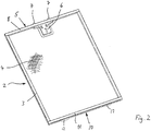
- An extractor hood 1 (see Fig. 1 ) or beveling, as it is usually arranged above cooking zones in kitchens, has at least one filter cassette 2 ( Fig. 1 ) containing, for example, a rectangular filter cassette frame 3 ( Fig. 2 ), the z. B. made of aluminum or stainless steel or the like and in cross-section in particular U-shaped.
- the filter cassette frame 3 holds as a filter medium z. B. several expanded metal layers 4 and, if necessary. Also filter fabric.
- the filter cartridge 2 is intended for use in the area of a suction surface 42 of the hood 1 or oblique.
- the filter cartridge 2 has at its front edge 5 facing an operator on a handle 6, the manual (see hand 43 in Fig. 1 ) Is mounted displaceably against spring force in the direction of an unlocking position and with the known manner z. B. two locking pins 7 are actuated, which are on the front frame part 8 of the filter cassette frame 3 by moving the handle 6 and retractable and as part of a filter cassette fastening device in releasable engagement on a front housing frame 9 of the hood. 1 are definable.
- the filter cassette 2 has at its rear edge 10 on a rear frame part 11 of the filter cassette frame 3 at least one engagement part 12 ( Fig. 2 schematically shows two engagement parts 12) projecting from the rear frame part 11.
- the engagement member 12 is in the form of an engagement or latching nose with a base 13, the z. B. is formed as a rectangular plate, and formed with a central part 14 which projects from the base 13.
- the engagement part 12 is in particular a plastic injection molded part.
- a locking device 15 has z. B. two spring legs 16, which are arranged starting from the base 13 on both sides spaced apart from the central part 14 and extending to approximately at the level of the end face 17 of the central part 14.
- the spring legs 16, which are in particular formed integrally with the base 13 and thus with the engagement part 12, are bulged away from the central part 14 to the outside and each have a front portion 18 inclined to the central part 14.
- the two mutually inclined front portions 18 form an assembly or centering cone of the latching device or on the engagement part 12th
- the rear frame part 11 of the filter cassette frame 3 contains in its end wall 19 for each engagement member 12 has an opening 20 whose rectangular surface is adapted to essentially play-free recording of the inserted engagement member 12 including the two spring legs 16.
- the base 13 and the rectangular plate is laterally beyond the engaging part 12 including the two spring legs 16 and forms a bearing collar 21 which rests on the inside of the rear frame part 11.
- a holding device, the z. B. two retaining webs 22 which protrude from the rear frame member 11 in the opening 20.
- the holding webs 22 engage in associated recesses 23 on the engaging part 12 and hold it firmly clamped on the rear frame part 11 when it is inserted or pressed into the opening 20 ( Fig. 6 ).
- the engagement part 12 may be in addition to this Attachment to the rear frame member 11 also glued or otherwise secured, z. B. screwed.
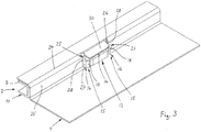
- the attachment or insertion of the filter cartridge 2 to the hood 1 is carried out by the filter cartridge 2 is guided with its rear edge 10 against a rear frame 24 of the cooker hood 1, which limits the suction back.
- the filter cartridge 2 is held in a slightly inclined position to the suction (see Fig. 1 ), z. B. at an angle of about 15 ° to the suction.
- the two engagement members 12 are brought into engagement with a respective receptacle 25 on the rear housing frame 24 of the hood 1.
- the receptacle 25 includes a substantially rectangular housing frame opening 26 in a standing perpendicular to the suction surface housing frame wall 24 ', through which the engagement member 12 is inserted through and in the direction of the plane of the filter cartridge 2 has a width which is less than the largest width of the Engagement part 12 between its two spring legs 16 at the bulges 27.
- the inclined front portions 18 of the two spring legs 16 form an assembly or Zentrierkonus initially facilitated with play in the direction of the plane of the filter cartridge 2 insertion into the rectangular housing frame opening 26.
- the two bulging spring leg 16 which are initially separated by a gap from the central part 14 of the engaging member 12, of the two the housing frame opening 26 delimiting edges 28 of the rear housing frame 24 resiliently against the central part 14 of the engaging part 12 is pressed, so that the engagement part 12 can be inserted with the two spring legs 16 through the housing frame opening 26.
- the spring legs 16 which have deformed back to their original position, with their base portions 29 at the edges 28 of the housing frame wall 24' of rear housing frame 24 substantially free of play and hold the filter cartridge 2 fixed by means of the locking device on the rear housing frame 24.
- the filter cartridge 2 is then pivoted with its front edge 5 to the front housing frame 9 of the hood 1 in its installed position and locked with the handle 6 and the locking pin 7 thereto.
- the filter cartridge 2 is attached by means of the filter cassette mounting device to the hood 1 and ready for their use in the area of the suction surface 42 of the hood 1 ready.
- the removal of the filter cartridge 2 from the extractor hood takes place in opposite movement (in Fig. 1 the two arrows on the front frame part 8 of the filter cassette frame 3 show the pivotal movement and the longitudinal movement of the filter cassette 2).
- the shape and arrangement of the spring legs 16 may also be such that they are not only resiliently pressed against the central part 14 of the engagement member 12 without their own deformation, but that they additionally deform elastically in particular in their bulging portion or bulge 27, while they are inserted through the housing frame opening 26 in contact with the edges 28 of the rear housing frame 24.
- the deformation or latching force can thus be influenced and adjusted by the design of the bulge 27 as well as by the choice of a suitable resilient material.
- the filter cartridge 2 With the filter cassette mounting device according to the invention, it is thus necessary, the filter cartridge 2 to overcome the deformation or latching resistance of the latching device 15 and the spring leg 16 when inserting and pushing the respective engaging member 12 with the two spring legs 16 as well as when removing or replacing consciously to touch.
- This deliberate firm grip of the filter cartridge 2 is particularly required when removing and removing the filter cartridge 2 from the hood 1, since this ensures that the held with power to release the latching device 15 in particular with both hands and guided almost parallel to the suction Filter cartridge 2 can not fall down in contrast to the insertion or removal of a filter cartridge, which does not have such a locking device and in which an operator inadvertently and lack of operating force does not keep the filter cartridge sufficiently secure.
- Such a locking device 15 provided essentially or exclusively on the filter cassette 2 has the advantage that such a filter cassette 2 can be used on a conventional holder or receptacle of an extractor hood 1, in particular in exchange for a filter cassette without such a latching device.
- a support such. B a support tab 30 may be provided (see Fig. 3 and 4 ), which extends from the housing frame 24 via the inserted engagement member 12 such that between its front edge 31 and the top 32 of the engagement member 12, a small gap 33 remains.
- the support tab 30 limits the pivot angle by the engagement member 12 applies after closing the gap 33 to the support tab 30 and further pivoting of the filter cartridge 2, in particular an unintentional pivoting down prevented.
- the upper side 32 of the engagement part 12 can be slightly bevelled together with the two spring legs 16 from the base 13 to the front end side 17 (see FIG Fig. 4 ), so that the initial insertion of the engaging member 12 is facilitated in the housing frame opening 26 by the reduced cross-section, with the inserted engagement member 12, the desired size of the gap 33 is set.
- the underside 32 'of the engagement member 12 may also be formed with the inclination of the top 32 so that the engagement member 12 is inserted into the opening 20 on the rear frame member 11 even in 180 ° rotated position and can be used with the filter cartridge frame 3.
- the engagement member 12 slides when inserted into the opening 26 of the rear housing frame 24 with its bottom 32 'on the opening 26 delimiting lower edge 24a of the housing frame wall 24' of the rear housing frame 24th
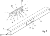
- Fig. 7 shows a further embodiment in which the rear frame part 11 of the filter cartridge 2 below the opening 20 an engagement member 34 in the form of a tongue-like tab 35 protrudes.
- the tongue-like tab 35 engages when inserting a cooker hood 1 in a receptacle 36, which is adapted as the tab 35 adapted slot 37 (in Fig. 7 shown only schematically) in the rear housing frame 24 of the hood 1 is formed.
- a latching device 15 comprises two springs 38, which - similar to the spring leg 16 of the first embodiment - protrude on both sides of the tab 35 from the rear frame part 11 and which, when the tab 35 is inserted into the slot 37, in the manner already described at the rear Housing frame 24 at the lateral slot edges 39 in resilient latching support.
- Fig. 8 shows a further embodiment in which - in a modification of the embodiment of the Fig. 7 -
- the latching device 15 is arranged on the rear housing frame 24 of the hood 1 and two springs or spring legs 40 (shown schematically by two arrows which symbolize the direction of the spring force), which are arranged such that they upon insertion of the engaging member 34 and Tab 35 in the slot 37 in spring-loaded latching contact with two lateral retaining lugs 41 which project laterally on the tab 35.
- the spring force device of the latching device 15 is thus arranged on the rear housing frame 24 of the extractor hood 1 and cooperates with the retaining lugs 41 on the engagement part 34 of the filter cassette frame 3 of the filter cassette 2.
- a support or support tab 30 may be provided which may prevent undesirable pivoting or tilting of the filter cartridge 2 during assembly or disassembly.
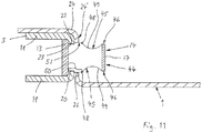
- One in the Fig. 9 to 11 shown modified embodiment of the fastening device has an engagement member 44, which compared to the in Fig. 5 illustrated engagement member 12 has a groove-like depression 45 at least on the top the central part 14 and the two spring legs 16 or additionally also on the underside.
- the groove-like depression 45 is formed such that a web 46 remains at least at the upper edge of the end face 17 of the central part 14 and preferably also an end point 47 on each spring leg 16 at the level of the web 46.
- the groove-like recess 45 extends from the web 46 to the base 13 to a holding portion 50 in front of the base 13, which is bounded by the dash-dotted line 48 and its original to the size of the opening 20 adapted outer contour corresponding to the engaging part 12 (see Fig.
- the central part 14 is z. B. formed as a hollow part with a plurality of walls 49, the upper edge is formed in each case in the shape of groove-like recess 45.
- the central part 14 may also be formed of solid material, which then has the groove-like recess 45.
- the engaging part 44 is inserted into the opening 20 of the rear frame part 11 such that a front portion or centering portion 51 of the holding portion 50 (see FIG Fig. 11 ) protrudes in front of the end wall 19 of the rear frame part 11.
- the engaging member 44 is inserted with its spring legs 16 through the housing frame opening 26, which is in the end wall 19 associated housing frame wall 24 ', passed through, initially at a slanted filter cartridge 2, the two opposite each other Webs 46 pass through the housing frame opening 26 and then the two groove-like depressions 45 in the region of the housing frame opening 26 limiting housing frame wall 24 'are arranged.
- the reduced by the recesses 45 cross section of the engaging member 44 allows an inclination of the filter cartridge 2 relative to its mounting position on the hood 1 in the housing frame opening 26, wherein at the same time the channel shape of the two wells 45 an independent holding the filter cartridge 2 on the housing frame 24 by means of the engagement member 44th allows.
- the engagement member 44 Upon complete insertion of the engaging member 44 in the housing frame opening 26 and concurrently pivoting the filter cartridge 2 in its filter position on the hood 1, the engagement member 44 is centered with its front portion or centering 51 in the housing frame opening 26 in the transverse direction (perpendicular to the longitudinal extent of the rear frame member 11) and through the spring legs 16 centered with their base portions 29 in the direction of the longitudinal extent of the rear frame part 11.
- a support tab 30 on the rear housing frame 24, as shown in the Fig. 3 and 4 is not required for the function of this engagement member 44 and therefore can be omitted, however, a support tab 30 can also be used with this engagement member 44 and support the function of the engagement member 44.
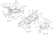
- FIG. 12 to 15 shown modified embodiment of the fastening device has an engagement member 52 with a latching device 15 which includes a leaf spring 53.
- the leaf spring 53 is formed in the manner of a clip or a clip with two spring legs 54 and pushed onto a central holding portion 55 of the engaging member 52, so that the spring base 56 surrounds the front edge 57 of the holding portion 55 and the two spring legs 54 on both sides of the holding portion 55 for Base 13 run.
- a z. B. slot-like recess 58 is formed, in which the respective spring leg 54 is inserted with its end portion 59.
- Each spring leg 54 includes two slots 60 extending inwardly from each side edge 61, e.g. B.
- the central holding portion 55 of the engaging portion 52 has a smaller thickness than the two side engaging portion end portions 66, so that each spring leg 54 is held centered between the two narrow end surfaces 67 of each of the two engaging portion end portions 66.
- the two spring legs 54 are preformed like a roof that they (see cross-sectional view of Fig. 15 ) starting from the spring base 56 toward their end portions 59 out initially from each other and in a spring shoulder 68 have their maximum distance. Starting from the spring shoulder 68 The two spring legs 54 approach each other towards their end portion 59 again.
- the engagement part 52 is inserted in the opening 20 of the rear frame part 11 (see Fig. 15 ) and therein according to the engagement part 12 (see Fig. 6 ) firmly attached.
- the engagement member 52 with the leaf spring 53 through the housing frame opening 26 (in Fig. 12 shown schematically) in the housing frame wall 24 'inserted through, wherein at an angle held filter cartridge 2, the two spring legs 54 in sliding contact at the two opposite and the housing frame opening 26 bounding edges 69 of the housing frame wall 24'.
- the distance between the two spring legs 54 between their spring shoulders 68 is greater than the height of the housing frame opening 26 between their edges 69, so that the spring legs 54 are pressed against each other while they are inserted with their spring shoulders 68 in the housing frame opening 26 and in this case a spring or Catching force for resilient deformation of the spring leg 54 must be overcome.
- the edges 69 of the housing frame wall 24 ' are in that area in which the spring legs 54 are again closer to each other and in contact with the housing wall 24 only low or no spring or latching force are loaded.
- the spring legs 54 are adjusted with such a spring force against their deformation that the leaf spring 53 can hold the filter cartridge 2 in its inclined position on the housing frame wall 24 ', even if an operator does not hold the filter cartridge 2 intentionally or unintentionally. When inserting a spring or latching force must therefore be overcome before the filter cartridge 2 is pivoted into its installed position.
- the filter cartridge 2 is swung out by the operator after manual unlocking by means of the handle 6 at its front edge 5 in its inclined mounting position and manually pulled out of the receptacle 25 and the housing frame opening 26, wherein the spring or latching force of the leaf spring 53 must be overcome.
- the spring or detent spring force thus acts in this leaf spring 53 perpendicular to the plane of the filter cartridge. 2
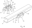
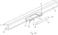
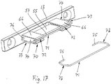
- One in the Fig. 16 and 17 shown modified embodiment of the fastening device has an engagement member 70, which is substantially the engagement member 52 according to the embodiment of Fig. 12 to 15
- a bow spring 71 as a latching device instead of the leaf spring 53 contains.
- the bow spring 71, z. B. a wire bow spring is mounted on the engaging member 70, for example, such that it with its central linear portion in a groove 72 (see also the illustrations of FIGS. 13 and 15 ) is inserted at each of the two engaging part end portions 66 and extends along the front edge 57 of the central holding portion 55 of the engaging part 70.
- the two end-side spring clips 73 are bent approximately in a U-shape and engage over the two outer surfaces 74 of the engagement part 70 or the engagement part end portions 66.
- the mutually bent-back strap ends 75 are inserted into bearing grooves 76 or bores in the outer surfaces 74 of the engagement part 70 are formed immediately in front of the base 13.
- the engagement part 70 is attached to the rear frame part 11 of the filter cassette frame 3 corresponding to the engagement part 52 of the above-described embodiment.
- the removal as well as the insertion of the filter cartridge 2 from or to the hood 1 is basically in accordance with the embodiment described above, wherein the spring or detent spring force of the bow spring 71 in the horizontal direction parallel to the rear frame part 11 of the filter cassette frame 3 during engagement of the deforming Spring clip 73 acts on the narrow-side slot or opening edges 39 of the housing frame opening 26.
- the engagement member 70 and 52 may be for receiving both the leaf spring 53 and the bow spring 71 according to the Fig. 12 to 17 be formed identically, z. B. as a plastic injection molded part.
- special designs of the Engagement members 52 and 70 may be useful with adapted for receiving the leaf spring as well as the bow spring configurations.
Landscapes
- Engineering & Computer Science (AREA)
- Chemical & Material Sciences (AREA)
- Combustion & Propulsion (AREA)
- Mechanical Engineering (AREA)
- General Engineering & Computer Science (AREA)
- Filtering Of Dispersed Particles In Gases (AREA)
Applications Claiming Priority (1)
| Application Number | Priority Date | Filing Date | Title |
|---|---|---|---|
| DE102016116379.1A DE102016116379A1 (de) | 2016-09-01 | 2016-09-01 | Filterkassetten-Befestigungsvorrichtung |
Publications (1)
| Publication Number | Publication Date |
|---|---|
| EP3290812A1 true EP3290812A1 (fr) | 2018-03-07 |
Family
ID=58347170
Family Applications (1)
| Application Number | Title | Priority Date | Filing Date |
|---|---|---|---|
| EP17160911.8A Withdrawn EP3290812A1 (fr) | 2016-09-01 | 2017-03-14 | Dispositif de fixation de cassette filtrante |
Country Status (2)
| Country | Link |
|---|---|
| EP (1) | EP3290812A1 (fr) |
| DE (1) | DE102016116379A1 (fr) |
Citations (5)
| Publication number | Priority date | Publication date | Assignee | Title |
|---|---|---|---|---|
| DE8804137U1 (de) * | 1988-03-26 | 1988-06-23 | Rentschler Reven Lüftungssysteme GmbH, 7126 Sersheim | Dunstabzugshaube |
| EP1291584A2 (fr) * | 2001-09-06 | 2003-03-12 | BSH Bosch und Siemens Hausgeräte GmbH | Dispositif de sécurité pour élément filtrant |
| DE10208475A1 (de) | 2002-02-27 | 2003-09-04 | Bsh Bosch Siemens Hausgeraete | Abzugshaube und Verfahren zum Wechseln oder Einsetzen von Filtern |
| DE10241313A1 (de) * | 2001-03-05 | 2004-03-18 | Imperial-Werke Ohg | Dunstabzugshaube |
| EP2789922A1 (fr) * | 2013-04-09 | 2014-10-15 | BSH Bosch und Siemens Hausgeräte GmbH | Hotte aspirante |
-
2016
- 2016-09-01 DE DE102016116379.1A patent/DE102016116379A1/de not_active Withdrawn
-
2017
- 2017-03-14 EP EP17160911.8A patent/EP3290812A1/fr not_active Withdrawn
Patent Citations (5)
| Publication number | Priority date | Publication date | Assignee | Title |
|---|---|---|---|---|
| DE8804137U1 (de) * | 1988-03-26 | 1988-06-23 | Rentschler Reven Lüftungssysteme GmbH, 7126 Sersheim | Dunstabzugshaube |
| DE10241313A1 (de) * | 2001-03-05 | 2004-03-18 | Imperial-Werke Ohg | Dunstabzugshaube |
| EP1291584A2 (fr) * | 2001-09-06 | 2003-03-12 | BSH Bosch und Siemens Hausgeräte GmbH | Dispositif de sécurité pour élément filtrant |
| DE10208475A1 (de) | 2002-02-27 | 2003-09-04 | Bsh Bosch Siemens Hausgeraete | Abzugshaube und Verfahren zum Wechseln oder Einsetzen von Filtern |
| EP2789922A1 (fr) * | 2013-04-09 | 2014-10-15 | BSH Bosch und Siemens Hausgeräte GmbH | Hotte aspirante |
Also Published As
| Publication number | Publication date |
|---|---|
| DE102016116379A1 (de) | 2018-03-01 |
Similar Documents
| Publication | Publication Date | Title |
|---|---|---|
| DE102005016486A1 (de) | Vorrichtung zum gelenkigen Verbinden eines Wischblatts mit einem Wischarm eines Scheibenwischers | |
| DE69301181T2 (de) | Kraftfahrzeug-Aussenspiegel | |
| EP0487965A1 (fr) | Clip en deux pièces pour la fixation des bandes de protection ou des enjoliveurs | |
| DE69403683T2 (de) | Verbindungs-und Gelenkeinrichtung zur Befestigung eines Scheibenwischblatts an einem Wischarm | |
| DE10163150A1 (de) | Gerätetür, vorzugsweise für einen Backofen | |
| DD201568A5 (de) | Abstreifer sowie werkzeug zur montage dieses abstreifers | |
| EP3050464B1 (fr) | Element de meuble avec element fonctionnel | |
| EP3636104B1 (fr) | Dispositif d'accouplement pour le guidage de coulisse | |
| DE2922269A1 (de) | Sohlenauflageplatte | |
| EP3290812A1 (fr) | Dispositif de fixation de cassette filtrante | |
| EP1437273B1 (fr) | Ensemble connecteur d'un dispositif d'essuie-glace pour vitres de véhicules automobiles | |
| EP1285778A2 (fr) | Plat de serrage | |
| DE202010014024U1 (de) | Leiterelement, insbesondere für eine Dachleiter | |
| EP2180283A2 (fr) | Boîte de culasse pour fusil à répétition | |
| DE2610107A1 (de) | Behaelter fuer messgeraete und dergleichen | |
| DE9205573U1 (de) | Griffbefestigung an Kochgeschirren o.dgl. | |
| DE69503316T2 (de) | Verbesserte elastische Befestigung | |
| DE2928118C2 (de) | Zur nebeneinander gereihten Befestigung an einer Montageschiene ausgebildetes Schalttafelelement, insbesondere Sicherungsautomat oder Trennschalter | |
| DE2811861C3 (de) | Feststeller für den schwenkbaren Flügel einer Fahrzeugtür | |
| DE19511104B4 (de) | Hängebeschlag | |
| DE102019117736A1 (de) | Innenschubkasten und Möbel oder Haushaltsgerät | |
| EP3666120A1 (fr) | Dispositif de raccordement de l'avant de tiroir et tiroir | |
| DE9105237U1 (de) | Blechschubkasten | |
| DE3729027C2 (fr) | ||
| DE7441626U (de) | Lösbare Sicherungsvorrichtung |
Legal Events
| Date | Code | Title | Description |
|---|---|---|---|
| PUAI | Public reference made under article 153(3) epc to a published international application that has entered the european phase |
Free format text: ORIGINAL CODE: 0009012 |
|
| AK | Designated contracting states |
Kind code of ref document: A1 Designated state(s): AL AT BE BG CH CY CZ DE DK EE ES FI FR GB GR HR HU IE IS IT LI LT LU LV MC MK MT NL NO PL PT RO RS SE SI SK SM TR |
|
| AX | Request for extension of the european patent |
Extension state: BA ME |
|
| STAA | Information on the status of an ep patent application or granted ep patent |
Free format text: STATUS: THE APPLICATION IS DEEMED TO BE WITHDRAWN |
|
| 18D | Application deemed to be withdrawn |
Effective date: 20180908 |