EP3290819B1 - Dispositif de chauffage électrique - Google Patents
Dispositif de chauffage électrique Download PDFInfo
- Publication number
- EP3290819B1 EP3290819B1 EP16187349.2A EP16187349A EP3290819B1 EP 3290819 B1 EP3290819 B1 EP 3290819B1 EP 16187349 A EP16187349 A EP 16187349A EP 3290819 B1 EP3290819 B1 EP 3290819B1
- Authority
- EP
- European Patent Office
- Prior art keywords
- heating
- housing
- elements
- heating element
- contact elements
- Prior art date
- Legal status (The legal status is an assumption and is not a legal conclusion. Google has not performed a legal analysis and makes no representation as to the accuracy of the status listed.)
- Active
Links
Images


Classifications
-
- F—MECHANICAL ENGINEERING; LIGHTING; HEATING; WEAPONS; BLASTING
- F24—HEATING; RANGES; VENTILATING
- F24H—FLUID HEATERS, e.g. WATER OR AIR HEATERS, HAVING HEAT-GENERATING MEANS, e.g. HEAT PUMPS, IN GENERAL
- F24H1/00—Water heaters, e.g. boilers, continuous-flow heaters or water-storage heaters
- F24H1/0072—Special adaptations
- F24H1/009—Special adaptations for vehicle systems
-
- B—PERFORMING OPERATIONS; TRANSPORTING
- B60—VEHICLES IN GENERAL
- B60H—ARRANGEMENTS OF HEATING, COOLING, VENTILATING OR OTHER AIR-TREATING DEVICES SPECIALLY ADAPTED FOR PASSENGER OR GOODS SPACES OF VEHICLES
- B60H1/00—Heating, cooling or ventilating devices
- B60H1/22—Heating, cooling or ventilating devices the heat source being other than the propulsion plant
- B60H1/2215—Heating, cooling or ventilating devices the heat source being other than the propulsion plant the heat being derived from electric heaters
- B60H1/2218—Heating, cooling or ventilating devices the heat source being other than the propulsion plant the heat being derived from electric heaters controlling the operation of electric heaters
-
- B—PERFORMING OPERATIONS; TRANSPORTING
- B60—VEHICLES IN GENERAL
- B60H—ARRANGEMENTS OF HEATING, COOLING, VENTILATING OR OTHER AIR-TREATING DEVICES SPECIALLY ADAPTED FOR PASSENGER OR GOODS SPACES OF VEHICLES
- B60H1/00—Heating, cooling or ventilating devices
- B60H1/22—Heating, cooling or ventilating devices the heat source being other than the propulsion plant
- B60H1/2215—Heating, cooling or ventilating devices the heat source being other than the propulsion plant the heat being derived from electric heaters
- B60H1/2221—Heating, cooling or ventilating devices the heat source being other than the propulsion plant the heat being derived from electric heaters arrangements of electric heaters for heating an intermediate liquid
-
- F—MECHANICAL ENGINEERING; LIGHTING; HEATING; WEAPONS; BLASTING
- F24—HEATING; RANGES; VENTILATING
- F24H—FLUID HEATERS, e.g. WATER OR AIR HEATERS, HAVING HEAT-GENERATING MEANS, e.g. HEAT PUMPS, IN GENERAL
- F24H9/00—Details
- F24H9/0005—Details for water heaters
- F24H9/001—Guiding means
- F24H9/0015—Guiding means in water channels
-
- F—MECHANICAL ENGINEERING; LIGHTING; HEATING; WEAPONS; BLASTING
- F24—HEATING; RANGES; VENTILATING
- F24H—FLUID HEATERS, e.g. WATER OR AIR HEATERS, HAVING HEAT-GENERATING MEANS, e.g. HEAT PUMPS, IN GENERAL
- F24H9/00—Details
- F24H9/18—Arrangement or mounting of grates or heating means
- F24H9/1809—Arrangement or mounting of grates or heating means for water heaters
- F24H9/1818—Arrangement or mounting of electric heating means
- F24H9/1827—Positive temperature coefficient [PTC] resistor
-
- H—ELECTRICITY
- H05—ELECTRIC TECHNIQUES NOT OTHERWISE PROVIDED FOR
- H05B—ELECTRIC HEATING; ELECTRIC LIGHT SOURCES NOT OTHERWISE PROVIDED FOR; CIRCUIT ARRANGEMENTS FOR ELECTRIC LIGHT SOURCES, IN GENERAL
- H05B1/00—Details of electric heating devices
- H05B1/02—Automatic switching arrangements specially adapted to apparatus ; Control of heating devices
- H05B1/0227—Applications
- H05B1/023—Industrial applications
- H05B1/0236—Industrial applications for vehicles
-
- H—ELECTRICITY
- H05—ELECTRIC TECHNIQUES NOT OTHERWISE PROVIDED FOR
- H05B—ELECTRIC HEATING; ELECTRIC LIGHT SOURCES NOT OTHERWISE PROVIDED FOR; CIRCUIT ARRANGEMENTS FOR ELECTRIC LIGHT SOURCES, IN GENERAL
- H05B3/00—Ohmic-resistance heating
- H05B3/40—Heating elements having the shape of rods or tubes
- H05B3/42—Heating elements having the shape of rods or tubes non-flexible
- H05B3/48—Heating elements having the shape of rods or tubes non-flexible heating conductor embedded in insulating material
-
- H—ELECTRICITY
- H05—ELECTRIC TECHNIQUES NOT OTHERWISE PROVIDED FOR
- H05B—ELECTRIC HEATING; ELECTRIC LIGHT SOURCES NOT OTHERWISE PROVIDED FOR; CIRCUIT ARRANGEMENTS FOR ELECTRIC LIGHT SOURCES, IN GENERAL
- H05B3/00—Ohmic-resistance heating
- H05B3/78—Heating arrangements specially adapted for immersion heating
-
- B—PERFORMING OPERATIONS; TRANSPORTING
- B60—VEHICLES IN GENERAL
- B60H—ARRANGEMENTS OF HEATING, COOLING, VENTILATING OR OTHER AIR-TREATING DEVICES SPECIALLY ADAPTED FOR PASSENGER OR GOODS SPACES OF VEHICLES
- B60H1/00—Heating, cooling or ventilating devices
- B60H1/22—Heating, cooling or ventilating devices the heat source being other than the propulsion plant
- B60H2001/2228—Heating, cooling or ventilating devices the heat source being other than the propulsion plant controlling the operation of heaters
-
- B—PERFORMING OPERATIONS; TRANSPORTING
- B60—VEHICLES IN GENERAL
- B60H—ARRANGEMENTS OF HEATING, COOLING, VENTILATING OR OTHER AIR-TREATING DEVICES SPECIALLY ADAPTED FOR PASSENGER OR GOODS SPACES OF VEHICLES
- B60H1/00—Heating, cooling or ventilating devices
- B60H1/22—Heating, cooling or ventilating devices the heat source being other than the propulsion plant
- B60H2001/2268—Constructional features
-
- H—ELECTRICITY
- H05—ELECTRIC TECHNIQUES NOT OTHERWISE PROVIDED FOR
- H05B—ELECTRIC HEATING; ELECTRIC LIGHT SOURCES NOT OTHERWISE PROVIDED FOR; CIRCUIT ARRANGEMENTS FOR ELECTRIC LIGHT SOURCES, IN GENERAL
- H05B2203/00—Aspects relating to Ohmic resistive heating covered by group H05B3/00
- H05B2203/02—Heaters using heating elements having a positive temperature coefficient
Definitions
- the invention relates to an electrical heating device, in particular for heating an interior of a motor vehicle.
- Motor vehicles usually have a heatable interior.
- motor vehicles with an internal combustion engine usually have a heating heat exchanger connected in the cooling circuit, through which hot coolant flows, which is heated by the internal combustion engine.
- the air flowing through the heating heat exchanger can be heated and fed to the interior.
- motor vehicles with fuel-efficient internal combustion engines that generate less waste heat and motor vehicles with plug-in/range extenders require auxiliary heating devices for interior heating.
- Motor vehicles with electric drives require heating devices, since heating with coolant heated by the internal combustion engine fails because they do not have an internal combustion engine.
- auxiliary heating devices such as electrical auxiliary heating devices, heat pump devices, fuel heaters, and auxiliary heating by means of exhaust gas heat exchangers.
- the electrical auxiliary heating has the advantage that the electrical heating devices required for this are relatively inexpensive compared to other solutions and that the heat generated can be felt relatively spontaneously because the electrical power is converted almost immediately into noticeable heat. Furthermore, electrical heating devices are space-saving and can therefore be installed flexibly in a motor vehicle.
- Such a heater or auxiliary heater as a heating device for high-voltage applications ie for voltages over 60 volts, must be designed in such a way that a hazard from the heating device during operation or maintenance can be ruled out.
- a heating device as auxiliary heaters or as sole heaters, there is basically the possibility that the electrical power is fed directly into a liquid medium, such as a coolant, which emits the heat into the interior of the motor vehicle via a further heat exchanger.
- a heating device is also referred to as a coolant-side heating device.
- Such a heating device is also referred to as an air-side heating device.
- the air-side heating devices are more spontaneous in terms of time, since almost one hundred percent of the electrical energy is converted into air heating.
- the efficiency is almost one hundred percent.
- it can only be used to heat the interior of the vehicle cabin. It is also usefully integrated in the vehicle interior, i.e. in the air conditioning unit.
- the integration of a high-voltage component in the interior is complex for safety reasons and generally means a more complex construction of the air conditioning unit, which increases the costs.
- the heating device on the coolant side is not quite as spontaneous and efficient in its heating effect, since the electrical energy is first used to warm up the fluid, for example in a small water circuit.
- the heated fluid or water is used in a separate coolant/air heat exchanger, as in a motor vehicle with an internal combustion engine, to heat the air flowing into the interior.
- coolant-side heating device is outside at various points of the interior can be mounted in the motor vehicle.
- the air conditioning unit can be used like in a classic motor vehicle without major design changes being necessary.
- a further advantage of the coolant-side heating device is the possibility of being able to also heat or warm up a battery, for example in the case of a purely electric vehicle, by the warm water or by the coolant.
- the DE 10 2010 060 446 A1 discloses a resistance heating device with a helical heating coil in a housing through which coolant flows. In this heating coil there is again a helical heating wire. The voltage drop or current flow occurs along this helically wound heating wire.
- the construction is very complex and therefore also expensive to manufacture.
- heating devices with PTC heating elements which are energized by means of contact electrodes, see EP 1 872 986 A1 .
- the heating elements only transfer their heat indirectly to the coolant, since the heating unit, consisting of heating elements and contact electrodes, is electrically insulated. In this case, the heat must at least pass through the electrical insulation made from poorly thermally conductive materials and through the housing of the coolant-carrying duct in order to heat up the coolant.
- the housing is a fairly solid cast body that has U-shaped recesses that protrude into the fluid chambers. The coolant then flows in a meandering manner around the U-shaped recesses.
- the heating elements which are insulated on both sides, are located in these fluid chambers.
- the heating unit consisting of PTC heating elements and contact electrodes, is then pressed into the U-shaped recesses using an aluminum clamping wedge. This compression creates electrical contact between the PTC heating elements and Contact electrodes and the thermal contact between the heating unit and the U-shaped recess.
- Such heaters are also by the EP 2 637 475 A1 and through the EP 2 440 004 B1 known.
- the heating devices according to the prior art also have disadvantages.
- the resistance heaters on the coolant side do not have any intrinsic safety of the heating unit with regard to excessive temperatures. It is therefore necessary to monitor the temperature and switch it off accordingly, for example if the coolant volume flow suddenly stops.
- the coolant-side PTC heating devices usually have a large number of heating units, which consist of 2 contact electrodes and PTC heating elements and insulation. This results in a rather high assembly effort.
- the cast housing results in heavy and large designs.
- the invention relates to an electrical heating device having a housing with a fluid inlet and a fluid outlet, with a number of openings being provided in a wall, into which heating elements are inserted and protruding into the interior of the housing, the heating elements having a heating element housing and a
- the heating element in the heating element housing has at least one heating means and the contact elements that make contact with at least one heating means and electrical insulation for insulating the contact elements from the heating element housing, the contact elements protruding in particular from the heating element and the heating elements with their heating element housing being inserted into the openings of the housing in this way , that the heating element housing are sealingly connected to the housing.
- the respective heating element can protrude into the housing through which the fluid to be heated flows, with a simple and cost-effective construction nevertheless being achieved.
- the heater housing is sealed to the housing by a thermal bonding method, such as by welding and/or brazing.
- the heating elements are encapsulated in such a way that the heating element housing is sealed except for a passage for the contact elements.
- the heating element housing is designed to be sealed to the outside with respect to the fluid to be heated, and the contact elements can nevertheless be guided out of the heating element housing in order to carry out the energization of the heating means.
- the contact elements are separated from the fluid to be heated and arranged in a sealed manner.
- the contact elements are carried out in a sealed manner in the passage. In this way it is achieved that even accidentally occurring fluid in the area of the contact elements cannot penetrate into the heating element.
- the heating element housing is formed from a tube that is open on one side, a deep-drawn or extruded tube element, or from two shells, such as half-shells. It can thereby be achieved that the heating element housing is more or less closed on the other side and has an opening only for the passage of the contact elements.
- the at least one heating means and the contact elements that make contact with the at least one heating means and the electrical insulation are inserted into the heating element housing as a preassembled unit.
- assembly can be considerably simplified and there are fewer errors, for example due to improper insulation.
- the heating element housing can then also be pressed or deformed, for example, in order to hold the elements used or the preassembled unit therein in a form-fitting manner.
- the housing is designed in at least two parts, and the housing consists of a base with the openings for receiving the heating elements and at least one further housing part.
- the heating device can be manufactured more simply, for example by deep-drawing individual housing parts of the housing, the housing parts of the housing then being connected to one another in a sealed manner in order to seal off the interior space through which the fluid flows. This can be done, for example, by soldering, welding or gluing, or by arranging a seal and by crimping or by flanging a corrugated slot.
- the housing is designed in at least two parts and the housing consists of a base with the openings for receiving the heating elements and at least one further housing part.
- the bottom can be flat and the other housing part can be trough-like.
- the bottom can also be curved, for example trough-shaped. In this case, the other housing part could also be flat.
- an electronic control unit which contacts the contact elements of the heating elements, the control unit being connected to the ground.
- the heating device with the electronic control unit can be manufactured compactly as a structural unit and installed together in the motor vehicle, for example in the engine compartment.
- deflection means are provided in the housing, which deflect a fluid flow between the fluid inlet and the fluid outlet.
- the flow path of the fluid to be heated is deflected and, in particular, also lengthened in order to achieve improved heat transfer with an acceptable pressure drop.
- the at least one heating means is connected over a large area to the contacting contact elements.
- the at least one heating means has or is a PTC element.
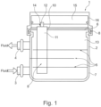
- the figure 1 shows a schematic representation of an electric heating device 1 with a housing 2.
- a Fluid inlet 3 and a fluid outlet 4 are provided, so that a fluid to be heated can flow through the fluid inlet into the housing, can flow through it and can be heated therein and can flow out of the housing 2 again through the fluid outlet 4 .
- Deflection means 5 can be provided in the housing 2, which deflect the fluid flow of the fluid to be heated in the housing 2 between the fluid inlet 3 and the fluid outlet 4 in order to bring about more favorable heating of the fluid to be heated with a suitable pressure drop.
- the deflection means 5 can be arranged as deflection walls, for example, in order to bring about a meandering fluid flow through the housing 2, for example.
- the housing 2 is designed in at least two parts, with a bottom 6 and a further housing part 7 being provided, which are tightly connected to one another.
- the base 6 can be positively connected to the housing part 7 and sealed. This can be done, for example, by a clamp connection or by a corrugated slot flanging by a mechanical connection.
- the base 6 can also be connected to the housing part 7 by soldering or welding or by gluing.
- Heating elements 9 protrude into the interior 13 of the housing and reach through openings 10 in the base 6, with the base 6 advantageously having a number of openings 10 as a wall, so that a corresponding number of heating elements 9 can protrude into the interior 13 of the housing 2 .
- the heating elements 9 are correspondingly inserted into the openings 10 of the base 6, the heating elements 9 being inserted into the base 6 in a sealing manner.
- the connection between the heating element 9 and the base 6 in the area of the openings 10 is made by welding and/or soldering.
- a heating element 9 has at least one heating element housing 11, in which at least one heating means 19 or a plurality of heating means 19 and the contact elements 12 making contact with the heating means 19 and electrical insulation 20 are arranged. At least two contact elements 12 are provided, which contact the heating element or elements 19 , the contact elements 12 being electrically insulated from the heating element housing 11 via the insulation 20 provided. In order to make contact with the contact elements 12 , they protrude from the heating element 9 or from the heating element housing 11 outside of the interior space 13 of the housing 2 from the heating element housing 11 .
- the heating elements 9 are inserted with their heating element housing 11 in a sealed manner into the openings 10 of the housing 2 in such a way that the housing 2 is sealed.
- the connection between the heater housing 11 and the housing 2 is sealed by a thermal bonding method such as welding and/or brazing. This creates a sealed, stable connection between the heating element housing 11 and the base 6 or the housing 2, so that the fluid can flow in the interior 13 of the housing 2 without the heating means 19 or the contact elements 12 coming into contact with the fluid .
- the heating elements 9 are correspondingly encapsulated, so that the heating element housing 11 is sealed off except for a passage 14 for the contact elements 12 . It is also preferred here if the contact elements 12 are guided through the passage 14 in a sealed manner. This can be done, for example, by the electrical insulation 20 provided or by an additional sealing element.
- the heating element housing 11 is formed from a tube which is open on one side, for example, to form the passage 14, the other side of the tube being sealed closed so that the closed portion of the tube can pass through the opening 10 in the base 6 into the Interior 13 of the housing 2 can protrude.
- the heating element housing 11 can be formed, for example, by a deep-drawn or extruded tube element, a welded or folded tube or by a tube manufactured in some other way.
- the heating element housing 11 can also be formed by a pocket which is formed, for example, from two shells, such as from two half-shells 52, 53.
- the formation of the heating element housing 11, for example by two shells, can preferably take place in that the two shells are thermally joined to one another at the edges, for example welded, soldered and/or glued, so that only the passage 14 for the contact elements 12 remains. It can also be advantageous if the passage 14 is also used for the insertion of the heating means 19, the contact elements 12 and the electrical insulation 20.
- the heating element or elements 19 and the contact elements 12 making contact with the at least one heating element 19 and the electrical insulation 20 are inserted into the heating element housing 11 as a preassembled unit.
- the preassembled unit can be prefabricated in order to be inserted into a heating element housing 11 provided.
- an electrical control unit 15 is provided according to the invention, which is electrically and/or mechanically connected to the contact elements 12 of the heating elements 9, so that the heating elements 9 can be controlled in a targeted manner.
- the electronic control unit 15 is connected to the floor 6 .
- the respective heating element 9 is encapsulated on its own, so that the respective heating element 9 protrudes into the interior space 13 of the housing 2 through which fluid flows. Since the respective heating elements 9 are thermally joined to the base 6, the current-carrying parts of the heating elements 9 are spatially and electrically or galvanically separated from the fluid flow. This is particularly advantageous for high-voltage applications with voltages greater than 60 volts.
- the base 6 and the heating element housing 11 are each prefabricated and connected to one another in a sealed manner by means of a thermal joining method, see above.
- the at least one heating means 19 with the contact elements 12 and the electrical insulation 20 can be inserted into the heating element housing 11, as pushed in, and the heating element housing 11 can be pressed, for example, for the positive connection of the components used, so that a favorable thermal contact of the elements is generated in the heater housing 11.
- the heating elements 9 can also be prefabricated and only then inserted into the openings in the base 6 and connected to the base 6 by a thermal joining method, for example.
- the heating element housing 11 can be produced, for example, by an extruded tube, an extruded part or a deep-drawn part. Alternatively, a welded tube or a folded tube can also be used, in which case after the introduction of the heating means 19, the contact elements 12 and the electrical insulation 20 the heating element housing 11 is pressed in order to improve the thermal contact between the heating means 19, the contact elements 12 and the insulation 20 with the heating element housing 11 in order to achieve a good heat transfer to the fluid to be heated.
- the heating element housing 11 can also be composed of two shells, such as two half-shells 52, 53, in which case the electrical insulation 20 with the heating means 19 and the contact elements 12 is inserted.
- the two shells 52, 53 can be connected to one another, for example, by thermal joining, ie welding, gluing or soldering.
- the shells are preferably joined to one another in a sealed manner at their edge.
- the shells or half-shells 52, 53 can also be joined mechanically, for example by flanging or deforming in some other way.
- the flow through the interior 13 of the housing 2 can be formed in a simple manner or with deflection of the fluid.
- the deflection means 5 can be provided for this purpose.
- the housing 2 can preferably be made of steel, aluminum or plastic and have a wall thickness of 1 to 4 mm, for example.
- the base 6 is preferably made of steel, aluminum or non-ferrous metal and advantageously has a material thickness of 0.5 to 3 mm.
- the heating element housing 11 is preferably made of steel, aluminum or non-ferrous metal and advantageously has a material thickness of 0.2 to 1 mm.
- the contact elements 12 are preferably designed as contact sheets made of aluminum or non-ferrous metal and advantageously have a material thickness of 0.2 to 1 mm.
- Alternative configurations of the housing 2, base 6, heating element housing 11 and/or contact element 12 can also have different dimensions or material thicknesses and materials.
- the electrical heating device 1 is preferably a high-voltage heating device for voltages of more than 60 volts or in particular of about 300 volts or more, with a large number of encapsulated heating elements 9, with a larger number of smaller encapsulated heating elements 9 or a smaller number of larger heating elements 9 being provided can.
- the elements of the heating elements 9 can be pushed into the heating element housing 11 and pressed or glued, or they can be inserted or glued into the shells or half-shells 52, 53, with the half-shells 52, 53 then being connected to one another in a sealed manner or beforehand, for example thermally be joined.
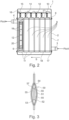
- the figure 2 shows an alternative embodiment of an electrical heating device 1 with a plurality of heating elements 9, which are arranged one after the other in the direction of flow of the fluid and optionally also in rows next to one another.
- the housing 2 is designed in several parts with a base 6, a further housing part 7, a lower housing cover 17 and a second base 18.
- the heating elements 9 can be inserted into the openings 10 of the base 6 and thermally joined and sealed, with the heating element housing 11 form a kind of tube matrix, which is arranged between the bases 6 and 18, the heating element housing being closed on one side and having a passage 14 for the contact elements 12 on the other side.
- the heating means 19 can also be seen as PTC elements, which are in electrical contact with the contact elements 12 on both sides, with the electrical insulation 20 being arranged around the contact elements 12 and the heating means 19 in order to prevent the combination of heating means 19 with contact elements 12 from the To insulate heating element housing 11 electrically.
- the control unit 15 is electrically connected to the contact elements 12, with the Control unit housing 16 is connected to the floor 6 in a mechanically sealed manner.
- PTC heating means can also be used instead of the PTC heating means. In principle, this also applies to all other exemplary embodiments in which PTC heating means or other heating means can be used.
- the figure 3 shows an embodiment of a heating element 50 in section with a heating element housing 51, which consists of two half-shells 52, 53, which are preferably thermally connected to one another, such as welded, soldered and/or glued.
- the half-shells 52, 53 have a passage 54 through which the contact elements 55 can protrude for electrical contacting, for example with a control unit.
- the heating element housing 51 In the heating element housing 51 are the heating means 56, on both sides of which the contact elements 55 and a peripheral electrical insulation 57 are arranged. Electrical insulation is generally solid, flexible, thin or thick insulation made of an electrically non-conductive insulating material.
- the figure 3 shows that the heating element is biconvex in section. In other exemplary embodiments, however, this can also be different, for example angular, rectangular, oval or round, etc.
- the biconvex shape is favorable for the pressure drop in the fluid.
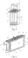
- the figure 4 shows another embodiment of an electric heater 1 similar to figure 1 in a partially sectioned view, the heating elements 9 with their heating element housings 11 being visible.
- the heating element housings 11 are inserted into the openings 10 of the base 6 at their upper end, with the contact elements 12 protruding from the heating elements 9 .
- the heating element housings 11 are designed as tubes that are closed on one side, with the heating means, the contact elements 12 and the electrical insulation 20 being inserted into the heating element housing 11 and the respective heating element housing then being pressed in the central area, so that there is favorable thermal contact between the elements of the heating element can be achieved with the heating element housing 11.
- the fluid to be heated can flow past the heating element housing on both sides in the direction of flow, so that a favorable flow guidance can be achieved.
- the tubes of the heating element housing are closed on the underside. This can be done by folding or by squeezing or by placing a closing element 21 or by welding, soldering or gluing.
- the openings 10 in the bottom 6 are designed as passages with a raised edge.
- the raised edge 23 can protrude into the interior 13 of the housing 2 or, as shown, point away from the interior 13 .
- the figure 5 shows an alternative electrical heating device 1, in which the heating elements 9 are designed as more flat elements, with the heating element housing 11 preferably being formed from shells, such as in particular half-shells 52, 53, so that the elements of the heating elements 9, i.e. the heating means 19 , the contact elements 12 and the electrical insulation 20 can be inserted into the shells or half-shells 52, 53 and glued, for example, with the two half-shells 52, 53 of the heating element housing 11 also being thermally joined at the edge 22, for example, such as being welded, soldered or glued in particular.
- the heating element housing 11 preferably being formed from shells, such as in particular half-shells 52, 53, so that the elements of the heating elements 9, i.e. the heating means 19 , the contact elements 12 and the electrical insulation 20 can be inserted into the shells or half-shells 52, 53 and glued, for example, with the two half-shells 52, 53 of the heating element housing 11 also being thermally joined at the edge 22, for example, such as being
- the design of the heating elements 9 is rather two-dimensional with a flat shape that shows a rectangular contour that almost fills the interior 13 of the housing 2 in the longitudinal direction.
- the heating elements 9 form a type of partition which causes a meandering flow through the housing 2 .
- the central heating element 9 bears against a rear wall of the housing 2 which is remote from the fluid inlet 3 and the fluid outlet 4 .
- the two outer heating elements 9 can, for example, also rest against the wall of the housing 2 in which the fluid inlet 3 and the fluid outlet 4 are arranged.
- the peripheral edge 22 of the heating element 9 runs almost completely, except for the passage 14, which is designed as an oval opening in order to lead the contact elements 12 out of the heating element 9 can.
- the passage 14 can also be designed in other ways and does not necessarily have to be oval in shape.
- the passages 14 of the adjacent heating elements 9 are offset from one another. The design of the passage 14 thus allows the heating elements 9 to come relatively close to one another transversely to the direction of flow of the fluid.
- FIGS. 4 and 5 show that an array of heating elements 9 can be formed in an adjacent array to each other.
- the heating elements 9 can be arranged in rows along and/or transversely to one another, ie in the direction of flow of the fluid or transversely thereto.
- the figure 6 shows schematically the arrangement of the elements of the heating elements 9, the heating means 19 and the contact elements 12 as well as the electrical insulation 20 being arranged in the circumferentially closed heating element housing 11.
- the electrical insulation 20 is formed by two insulating elements. It can also be formed by a single, for example, tube-like element.
- the heater housing 11 is rectangular in section. This can also be designed in other ways, such as round, oval, square, etc.
- the figure 7 shows an embodiment of an electric heating device 1 similar to FIG figure 2 , where the heating elements are 9 in figure 7 are arranged transversely to the direction of flow S between fluid inlet 3 and fluid outlet 4, while in figure 1 are arranged along the flow direction 5 between the fluid inlet 3 and the fluid outlet 4 .
- This means that the flow of the fluid to be heated between the fluid inlet 3 and the fluid outlet 4 in figure 2 preferably runs in a direction parallel to a plane between the fluid inlet and the fluid outlet, with the flow essentially parallel to the heating elements.
- the heating elements 9 are arranged essentially transversely to the direction of flow S between the fluid inlet 3 and the fluid outlet 4, so that a fluid flow also occurs essentially perpendicularly to a plane between the fluid inlet and the fluid outlet, i.e. between the heating elements 9, with the fluid being deflected at least twice, to be deflected starting from the fluid inlet 3, then to flow transversely between the heating elements 9 and then to be deflected again to the fluid outlet 4.
- the Figures 8 to 10 show an embodiment in which the heating elements 9 are viewed in two rows perpendicular to the direction of flow and in at least two columns are arranged one after the other in the direction of flow, so that a total of at least four or more heating elements 9 are arranged.
- the heating elements 9 are arranged within the housing 2, ie in two rows, with at least two or more heating elements 9 being able to be arranged in one row.
- a plurality of heating elements 9 can also be arranged in a row one after the other.
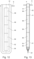
- the Figures 11 to 13 show details of heater housings 11 according to FIG figure 3 .
- the heating element housing 11 are formed in accordance with two shells 52, 53, according to figure 11 the electrical insulation 20 is designed as a molded part which almost completely encloses the contact elements 55 and the heating means 56, it being possible for one molded part or two molded parts to be provided as the electrical insulation 20.
- the half-shells 52, 53 have an edge 22 lying against one another, which is used to connect the half-shells 52, 53, for example by soldering, welding and/or gluing.
- the half-shells 52, 53 are also connected to the base 6 by thermal joining, for example by soldering, welding and/or gluing.
- the Figures 14 to 16 show another exemplary embodiment of an electrical heating device 1, in which several rows of heating means 19 are arranged in the heating elements 9 in the longitudinal direction of the heating element housing 11, the heating means 19 making electrical contact with one another via contact elements 12.
- the contact elements 12 can be provided for a row of heating means 19 , with the electrical insulation 20 electrically insulating the respective contact elements 12 from the heating element housing 11 .
- a few larger heating elements 9 are preferably provided, which are arranged, for example, in one to three stages.
- FIGS 17 to 19 show corresponding representations of heating devices 1, in which heating elements 9 are provided with a plurality of heating means 19. That's how they show Figures 19 and 20 that within a heating element 9, for example, three columns with five rows of heating means 19 are arranged. These can be contacted, for example, in columns or as a whole by individual or flat contact elements 12, so that, for example, only 1, 2 or 3 or a small number of such flat heating elements are arranged next to one another, in particular between fluid inlet 3 and fluid outlet 4. So that the heating means 19 are so geometric are arranged, auxiliary frames can be provided which position the heating means 19 in the heating element housing 11 . Other geometric arrangements of heating means in the heating element housing are also possible. Such geometric arrangements allow the heating means 19 to be evenly distributed over the surface in the heating element housing 11, so that the heating element housing 11 is heated evenly, particularly in the case of more extensive, more flat heating elements.
- Figures 21 to 23 Figure 1 shows alternative heating devices 1, in which three heating elements are arranged adjacent to each other, in each heating element two columns with six rows of heating means 19 are arranged.
- the heating means 19 of a heating element 9 are each contacted by flat contact elements 12 on one side, so that the heating elements can be controlled as a whole.
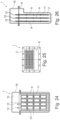
- the Figures 24 to 26 show an electrical heating device 1 with an electronic control unit 15, which contacts the contact elements 12 for controlling the heating means 19 for heating a fluid flowing through.
- the heating means 19 are arranged in rows and columns within a heating element 9, with three heating elements 9 being arranged next to one another and adjacent to one another.
- the respective heating element 9 can be switched on or off as a whole or can be controlled in terms of the heat output, or different groups of heating means 19 can be interconnected within a heating element 9 in order to effect finer control within a respective heating element 9 to be able to For example, each column of heating means 19 can be controlled individually.
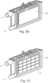
- FIGS. 27 to 31 show explanations accordingly figure 5 , wherein the heating means 19 according to figure 31 are arranged in rows and columns, the contact elements 12 according to figure 30 are flat elements that contact all heating means 19 of a heating element 9 .
- the heating means 19 of a heating element 9 can be controlled jointly via the control of the two opposing contact elements 12 . With the arrangement of three such heating elements 9, a corresponding control of the electrical heating device can be achieved.
- the heating device and/or the heating elements is/are tightly closed or encapsulated.
- a thermal joining method of the heating device and/or the heating elements can be used.
- the heating means can be designed as PTC elements. Alternatively, elements without a PTC effect can be used.
- the heating means are preferably energized via 2 contact elements as contact electrodes.
- the heating means are therefore arranged between two contact elements, such as contact electrodes.
- heating means 19 which are arranged between two sheet-like contact elements
- a heating means for example as Heating ceramics are used, which is provided with applied and / or printed resistance track or resistance tracks.
- This resistive track would then be electrically connected to achieve current flow.
- the resistance track would function as a contact element.
- a carrier material for example made of insulating ceramics and/or aluminum oxide with good thermal conductivity, is provided with applied resistance tracks as contact elements and contacted. The current then possibly does not flow over the short path from contact element to contact element, but over the long path over the length of the applied resistance track.
- the heating device can preferably be used for high-voltage applications.
- a trough with an essentially flat cover can also be provided.
- the electrical contacting of the heating elements is usually perpendicular to the direction of flow of the fluid to be heated.
- a rigid or flexible material or element such as a molded element or foil, can be used as electrical insulation.
- an arrangement of turbulence generators for increasing the output is also possible between the heating elements 9 and/or between the heating elements and the housing 2.
- the bottom 6 for receiving and arranging the heating elements is used in an advantageous embodiment, the direct contact Control unit with power electronics.
- the base 6 serves to close off the housing 2.
- the base 6 is used to fasten and seal the control unit or the power electronics and to seal the housing 2 through which fluid flows.
- the nominal electrical power of the heating device 1 can be in the range from 3 kW to about 9 kW, preferably about 5 kW.
Landscapes
- Engineering & Computer Science (AREA)
- Physics & Mathematics (AREA)
- Thermal Sciences (AREA)
- Mechanical Engineering (AREA)
- Chemical & Material Sciences (AREA)
- Combustion & Propulsion (AREA)
- General Engineering & Computer Science (AREA)
- Air-Conditioning For Vehicles (AREA)
- Instantaneous Water Boilers, Portable Hot-Water Supply Apparatuses, And Control Of Portable Hot-Water Supply Apparatuses (AREA)
Claims (8)
- Dispositif de chauffage électrique (1) comprenant un boîtier (2) comportant une entrée de fluide (3) et une sortie de fluide (4), où il est prévu, dans une paroi du boîtier (2), un certain nombre d'ouvertures (10) dans lesquelles sont introduits des éléments chauffants (9, 50) qui dépassent dans l'espace intérieur (13) du boîtier (2), où les éléments chauffants (9, 50) présentent un boîtier d'élément chauffant (11, 51), et où un élément chauffant (9, 50) présente, dans le boîtier d'élément chauffant (11, 51), au moins un moyen de chauffage (19, 56), et l'au moins un moyen de chauffage (19, 56) présente des éléments de contact (12, 55) assurant la mise en contact, et une isolation électrique servant à l'isolation des éléments de contact (12, 55) par rapport au boîtier d'élément chauffant (11, 51), où les éléments chauffants (9, 50), avec leur boîtier d'élément chauffant (11, 51), sont introduits dans les ouvertures (10) de la paroi du boîtier (2), de manière telle que les boîtiers d'éléments chauffants (11, 51) soient reliés de façon étanche au boîtier (2), caractérisé en ce que le boîtier d'élément chauffant (11, 51) est relié au boîtier (2) en étant rendu étanche par un procédé d'assemblage thermique, et est assemblé par un processus tel que le soudage et/ou le brasage, où le boîtier (2) est configuré au moins en deux parties et se compose d'un fond (6, 18) comportant les ouvertures (10) servant au logement des éléments chauffants (9, 50), et ledit boîtier se compose au moins d'une autre partie de boîtier (7), et où il est prévu en outre une unité de commande électronique (15) qui met en contact les éléments de contact (12, 55) des éléments chauffants (9, 50), où l'unité de commande (15) est reliée au fond (6, 18).
- Dispositif de chauffage électrique (1) selon la revendication 1, caractérisé en ce que les éléments chauffants (9, 50) sont encapsulés de manière telle, que le boîtier d'élément chauffant (11, 51) soit obturé de façon étanche, à l'exception d'un passage (54) pour les éléments de contact (12, 55).
- Dispositif de chauffage électrique (1) selon la revendication 2, caractérisé en ce que les éléments de contact (12, 55) sont réalisés en étant rendus étanches dans le passage (54).
- Dispositif de chauffage électrique (1) selon l'une quelconque des revendications précédentes, caractérisé en ce que le boîtier d'élément chauffant (11, 51) est formé par un tube ouvert d'un côté, par un élément tubulaire embouti ou extrudé, ou bien formé par deux coques, comme des demi-coques (52, 53).
- Dispositif de chauffage électrique (1) selon l'une quelconque des revendications précédentes, caractérisé en ce que l'au moins un moyen de chauffage (19, 56) et les éléments de contact (12, 55) assurant la mise en contact de l'au moins un moyen de chauffage (19, 56) et l'isolation électrique (20, 57) sont introduits dans le boîtier d'élément chauffant (11, 51) comme unité prémontée.
- Dispositif de chauffage électrique (1) selon l'une quelconque des revendications précédentes, caractérisé en ce qu'il est prévu, dans le boîtier (2), des moyens de redirection (5) qui redirigent un flux de fluide entre l'entrée de fluide (3) et la sortie de fluide (4).
- Dispositif de chauffage électrique (1) selon l'une quelconque des revendications précédentes, caractérisé en ce que l'au moins un moyen de chauffage (19, 56) est relié à plat aux éléments de contact (12, 55) assurant la mise en contact.
- Dispositif de chauffage électrique (1) selon l'une quelconque des revendications précédentes, caractérisé en ce que l'au moins un moyen de chauffage (19, 56) présente ou est un élément CTP.
Priority Applications (2)
| Application Number | Priority Date | Filing Date | Title |
|---|---|---|---|
| EP16187349.2A EP3290819B1 (fr) | 2016-09-06 | 2016-09-06 | Dispositif de chauffage électrique |
| CN201710786099.6A CN107791786B (zh) | 2016-09-06 | 2017-09-04 | 电加热设备 |
Applications Claiming Priority (1)
| Application Number | Priority Date | Filing Date | Title |
|---|---|---|---|
| EP16187349.2A EP3290819B1 (fr) | 2016-09-06 | 2016-09-06 | Dispositif de chauffage électrique |
Publications (2)
| Publication Number | Publication Date |
|---|---|
| EP3290819A1 EP3290819A1 (fr) | 2018-03-07 |
| EP3290819B1 true EP3290819B1 (fr) | 2023-03-15 |
Family
ID=56883643
Family Applications (1)
| Application Number | Title | Priority Date | Filing Date |
|---|---|---|---|
| EP16187349.2A Active EP3290819B1 (fr) | 2016-09-06 | 2016-09-06 | Dispositif de chauffage électrique |
Country Status (2)
| Country | Link |
|---|---|
| EP (1) | EP3290819B1 (fr) |
| CN (1) | CN107791786B (fr) |
Families Citing this family (10)
| Publication number | Priority date | Publication date | Assignee | Title |
|---|---|---|---|---|
| DE102018215398A1 (de) | 2018-09-11 | 2020-03-12 | Mahle International Gmbh | Elektrische Heizeinrichtung |
| DE102018217030A1 (de) * | 2018-10-04 | 2020-04-09 | Mahle International Gmbh | Elektrische Heizeinrichtung |
| DE102019213862A1 (de) | 2019-09-11 | 2021-03-11 | Mahle International Gmbh | PTC-Heizeinrichtung |
| EP3904781B1 (fr) * | 2020-04-30 | 2024-03-06 | Mahle International GmbH | Dispositif de chauffage électrique |
| US12049124B2 (en) | 2020-05-15 | 2024-07-30 | Eberspächer Catem Gmbh & Co. Kg | PTC heating assembly and method for manufacturing the same |
| DE102021104371A1 (de) * | 2021-02-24 | 2022-08-25 | Audi Aktiengesellschaft | Kraftfahrzeug und Verfahren zur Anpassung einer verfügbaren Heizleistung in einem Kraftfahrzeug |
| DE102021110624A1 (de) | 2021-04-26 | 2022-10-27 | Eberspächer Catem Gmbh & Co. Kg | Elektrische heizvorrichtung und verfahren zu deren herstellung |
| CN114909806B (zh) * | 2022-05-19 | 2023-12-29 | 衡水中科衡发动力装备有限公司 | 高压流体微通道电加热器及其制造方法 |
| DE102024116220A1 (de) * | 2024-06-11 | 2025-12-11 | Eberspächer Catem Gmbh & Co. Kg | Elektrische Heizvorrichtung |
| FR3165373A1 (fr) * | 2024-08-05 | 2026-02-06 | Valeo Systemes Thermiques | Dispositif de chauffage electrique d’un fluide |
Family Cites Families (21)
| Publication number | Priority date | Publication date | Assignee | Title |
|---|---|---|---|---|
| ES2354964T3 (es) | 2006-06-28 | 2011-03-21 | EBERSPÄCHER CATEM GMBH & CO. KG | Dispositivo de calefacción eléctrico. |
| DE102010060446A1 (de) | 2009-11-09 | 2011-05-12 | Dbk David + Baader Gmbh | Elektrischer Heizer |
| JP2011152907A (ja) * | 2010-01-28 | 2011-08-11 | Mitsubishi Heavy Ind Ltd | 電気式加熱装置及び車両用空気調和装置 |
| EP2440004B1 (fr) | 2010-10-08 | 2015-02-25 | Eberspächer catem GmbH & Co. KG | Dispositif de chauffage électrique |
| DE102011003296A1 (de) * | 2011-01-28 | 2012-08-02 | Behr Gmbh & Co. Kg | Wärmeübertrager |
| EP2562485B1 (fr) * | 2011-08-25 | 2020-10-07 | HOMAG GmbH | Chauffage de milieux |
| DE102011054406B4 (de) * | 2011-09-30 | 2013-05-23 | Borgwarner Beru Systems Gmbh | Elektrische Heizvorrichtung zum Beheizen von Flüssigkeiten |
| DE102011088773A1 (de) * | 2011-12-15 | 2013-06-20 | Behr Gmbh & Co. Kg | Elektrisch betreibbares Heizgerät |
| EP2637475B9 (fr) | 2012-03-08 | 2017-01-25 | Eberspächer catem GmbH & Co. KG | Elément chauffant |
| CN202488780U (zh) * | 2012-03-16 | 2012-10-10 | 河北宏业永盛汽车加热器股份有限公司 | 电动汽车空调系统用ptc电加热器 |
| FR2989034B1 (fr) * | 2012-04-06 | 2014-03-28 | Valeo Systemes Thermiques | Dispositif de chauffage electrique de fluide pour vehicule automobile et procede d'assemblage dudit dispositif de chauffage |
| DE102012207301A1 (de) * | 2012-05-02 | 2013-11-07 | Webasto Ag | Heizvorrichtung für ein Fahrzeug und Verfahren zum Kühlen einer elektronischen Steuereinrichtung der Heizvorrichtung |
| KR102078194B1 (ko) * | 2012-05-16 | 2020-02-19 | 한온시스템 주식회사 | 차량용 히터 |
| CN103517468B (zh) * | 2012-06-27 | 2015-03-04 | 比亚迪股份有限公司 | 一种ptc电热元件、电加热装置以及电动车 |
| JP2014019287A (ja) * | 2012-07-18 | 2014-02-03 | Sanden Corp | 加熱装置及び加熱装置の製造方法 |
| DE102013101792B4 (de) * | 2013-02-22 | 2025-11-06 | Wolf Gmbh | Wärmepumpe |
| EP2797381B1 (fr) * | 2013-04-26 | 2016-03-09 | Eberspächer catem GmbH & Co. KG | Dispositif de chauffage électrique et son procédé de fabrication |
| KR20150025221A (ko) * | 2013-08-28 | 2015-03-10 | 현대자동차주식회사 | 차량용 히터 장치 |
| EP2884199B1 (fr) * | 2013-12-13 | 2016-11-23 | Eberspächer catem GmbH & Co. KG | Dispositif de chauffage électrique |
| DE102014015586B3 (de) * | 2014-10-21 | 2016-03-31 | Webasto SE | Heizgerät |
| CN204956023U (zh) * | 2015-09-06 | 2016-01-13 | 镇江东方电热科技股份有限公司 | 集成式电子自动控制系统的新能源汽车ptc电加热器 |
-
2016
- 2016-09-06 EP EP16187349.2A patent/EP3290819B1/fr active Active
-
2017
- 2017-09-04 CN CN201710786099.6A patent/CN107791786B/zh active Active
Also Published As
| Publication number | Publication date |
|---|---|
| CN107791786B (zh) | 2022-06-10 |
| EP3290819A1 (fr) | 2018-03-07 |
| CN107791786A (zh) | 2018-03-13 |
Similar Documents
| Publication | Publication Date | Title |
|---|---|---|
| EP3290819B1 (fr) | Dispositif de chauffage électrique | |
| EP3290821A1 (fr) | Dispositif de chauffage électrique | |
| EP2499436B1 (fr) | Dispositif de chauffage électrique | |
| DE4433814B4 (de) | Kraftfahrzeug | |
| EP2917555B1 (fr) | Dispositif de préchauffage destiné à un système d'injection de carburant | |
| EP3493650A1 (fr) | Dispositif de chauffage électrique | |
| DE102009058673A1 (de) | Thermoelektrischer Wärmetauscher | |
| WO2013087671A1 (fr) | Appareil de chauffage fonctionnant à l'électricité | |
| EP2854211A1 (fr) | Dispositif de chauffage et de refroidissement pour une batterie | |
| DE102015208999A1 (de) | Energiespeicher eines Kraftfahrzeugs | |
| EP3290820A1 (fr) | Dispositif de chauffage électrique | |
| EP0707434B2 (fr) | Radiateur pour système de chauffage d'un véhicule à moteur | |
| DE102017114330A1 (de) | Batterieanordnung und Verfahren zur Kühlung einer Batterieanordnung | |
| DE102015220759A1 (de) | Wärmeübertrager, insbesondere thermoelektrische Wärmepumpe, zum Temperieren einer Batterie | |
| DE102017207738A1 (de) | Elektrische Heizeinrichtung | |
| DE102018205316A1 (de) | Elektrische Heizeinrichtung | |
| WO2019115255A1 (fr) | Échangeur de chaleur à plaques | |
| EP2837042B1 (fr) | Générateur thermoélectrique comprenant un échangeur de chaleur | |
| WO2016041690A1 (fr) | Dispositif thermoélectrique, notamment générateur thermoélectrique pour véhicule à moteur | |
| DE102014219853A1 (de) | Thermoelektrischer Generator | |
| DE102016218140A1 (de) | Brennstoffzellenstapel | |
| DE102018205314A1 (de) | Elektrische Heizeinrichtung | |
| EP3557155A1 (fr) | Dispositif de chauffage électrique | |
| DE102018205319A1 (de) | Elektrische Heizeinrichtung | |
| WO2018158286A1 (fr) | Dispositif de chauffage |
Legal Events
| Date | Code | Title | Description |
|---|---|---|---|
| PUAI | Public reference made under article 153(3) epc to a published international application that has entered the european phase |
Free format text: ORIGINAL CODE: 0009012 |
|
| STAA | Information on the status of an ep patent application or granted ep patent |
Free format text: STATUS: THE APPLICATION HAS BEEN PUBLISHED |
|
| AK | Designated contracting states |
Kind code of ref document: A1 Designated state(s): AL AT BE BG CH CY CZ DE DK EE ES FI FR GB GR HR HU IE IS IT LI LT LU LV MC MK MT NL NO PL PT RO RS SE SI SK SM TR |
|
| AX | Request for extension of the european patent |
Extension state: BA ME |
|
| STAA | Information on the status of an ep patent application or granted ep patent |
Free format text: STATUS: REQUEST FOR EXAMINATION WAS MADE |
|
| 17P | Request for examination filed |
Effective date: 20180907 |
|
| RAX | Requested extension states of the european patent have changed |
Extension state: ME Payment date: 20180907 Extension state: BA Payment date: 20180907 |
|
| RBV | Designated contracting states (corrected) |
Designated state(s): AL AT BE BG CH CY CZ DE DK EE ES FI FR GB GR HR HU IE IS IT LI LT LU LV MC MK MT NL NO PL PT RO RS SE SI SK SM TR |
|
| STAA | Information on the status of an ep patent application or granted ep patent |
Free format text: STATUS: EXAMINATION IS IN PROGRESS |
|
| 17Q | First examination report despatched |
Effective date: 20190927 |
|
| GRAP | Despatch of communication of intention to grant a patent |
Free format text: ORIGINAL CODE: EPIDOSNIGR1 |
|
| STAA | Information on the status of an ep patent application or granted ep patent |
Free format text: STATUS: GRANT OF PATENT IS INTENDED |
|
| RIC1 | Information provided on ipc code assigned before grant |
Ipc: H05B 3/48 20060101ALI20221011BHEP Ipc: H05B 1/02 20060101ALI20221011BHEP Ipc: H05B 3/78 20060101ALI20221011BHEP Ipc: F24H 9/00 20060101ALI20221011BHEP Ipc: F24H 9/1818 20220101ALI20221011BHEP Ipc: F24H 1/00 20060101AFI20221011BHEP |
|
| INTG | Intention to grant announced |
Effective date: 20221103 |
|
| GRAJ | Information related to disapproval of communication of intention to grant by the applicant or resumption of examination proceedings by the epo deleted |
Free format text: ORIGINAL CODE: EPIDOSDIGR1 |
|
| GRAL | Information related to payment of fee for publishing/printing deleted |
Free format text: ORIGINAL CODE: EPIDOSDIGR3 |
|
| GRAS | Grant fee paid |
Free format text: ORIGINAL CODE: EPIDOSNIGR3 |
|
| STAA | Information on the status of an ep patent application or granted ep patent |
Free format text: STATUS: EXAMINATION IS IN PROGRESS |
|
| GRAP | Despatch of communication of intention to grant a patent |
Free format text: ORIGINAL CODE: EPIDOSNIGR1 |
|
| STAA | Information on the status of an ep patent application or granted ep patent |
Free format text: STATUS: GRANT OF PATENT IS INTENDED |
|
| INTC | Intention to grant announced (deleted) | ||
| GRAA | (expected) grant |
Free format text: ORIGINAL CODE: 0009210 |
|
| STAA | Information on the status of an ep patent application or granted ep patent |
Free format text: STATUS: THE PATENT HAS BEEN GRANTED |
|
| INTG | Intention to grant announced |
Effective date: 20230120 |
|
| AK | Designated contracting states |
Kind code of ref document: B1 Designated state(s): AL AT BE BG CH CY CZ DE DK EE ES FI FR GB GR HR HU IE IS IT LI LT LU LV MC MK MT NL NO PL PT RO RS SE SI SK SM TR |
|
| REG | Reference to a national code |
Ref country code: CH Ref legal event code: EP Ref country code: GB Ref legal event code: FG4D Free format text: NOT ENGLISH |
|
| REG | Reference to a national code |
Ref country code: DE Ref legal event code: R096 Ref document number: 502016015633 Country of ref document: DE |
|
| REG | Reference to a national code |
Ref country code: IE Ref legal event code: FG4D Free format text: LANGUAGE OF EP DOCUMENT: GERMAN |
|
| REG | Reference to a national code |
Ref country code: AT Ref legal event code: REF Ref document number: 1554218 Country of ref document: AT Kind code of ref document: T Effective date: 20230415 |
|
| REG | Reference to a national code |
Ref country code: LT Ref legal event code: MG9D |
|
| REG | Reference to a national code |
Ref country code: NL Ref legal event code: MP Effective date: 20230315 |
|
| PG25 | Lapsed in a contracting state [announced via postgrant information from national office to epo] |
Ref country code: RS Free format text: LAPSE BECAUSE OF FAILURE TO SUBMIT A TRANSLATION OF THE DESCRIPTION OR TO PAY THE FEE WITHIN THE PRESCRIBED TIME-LIMIT Effective date: 20230315 Ref country code: NO Free format text: LAPSE BECAUSE OF FAILURE TO SUBMIT A TRANSLATION OF THE DESCRIPTION OR TO PAY THE FEE WITHIN THE PRESCRIBED TIME-LIMIT Effective date: 20230615 Ref country code: LV Free format text: LAPSE BECAUSE OF FAILURE TO SUBMIT A TRANSLATION OF THE DESCRIPTION OR TO PAY THE FEE WITHIN THE PRESCRIBED TIME-LIMIT Effective date: 20230315 Ref country code: LT Free format text: LAPSE BECAUSE OF FAILURE TO SUBMIT A TRANSLATION OF THE DESCRIPTION OR TO PAY THE FEE WITHIN THE PRESCRIBED TIME-LIMIT Effective date: 20230315 Ref country code: HR Free format text: LAPSE BECAUSE OF FAILURE TO SUBMIT A TRANSLATION OF THE DESCRIPTION OR TO PAY THE FEE WITHIN THE PRESCRIBED TIME-LIMIT Effective date: 20230315 |
|
| PG25 | Lapsed in a contracting state [announced via postgrant information from national office to epo] |
Ref country code: SE Free format text: LAPSE BECAUSE OF FAILURE TO SUBMIT A TRANSLATION OF THE DESCRIPTION OR TO PAY THE FEE WITHIN THE PRESCRIBED TIME-LIMIT Effective date: 20230315 Ref country code: NL Free format text: LAPSE BECAUSE OF FAILURE TO SUBMIT A TRANSLATION OF THE DESCRIPTION OR TO PAY THE FEE WITHIN THE PRESCRIBED TIME-LIMIT Effective date: 20230315 Ref country code: GR Free format text: LAPSE BECAUSE OF FAILURE TO SUBMIT A TRANSLATION OF THE DESCRIPTION OR TO PAY THE FEE WITHIN THE PRESCRIBED TIME-LIMIT Effective date: 20230616 Ref country code: FI Free format text: LAPSE BECAUSE OF FAILURE TO SUBMIT A TRANSLATION OF THE DESCRIPTION OR TO PAY THE FEE WITHIN THE PRESCRIBED TIME-LIMIT Effective date: 20230315 |
|
| PG25 | Lapsed in a contracting state [announced via postgrant information from national office to epo] |
Ref country code: SM Free format text: LAPSE BECAUSE OF FAILURE TO SUBMIT A TRANSLATION OF THE DESCRIPTION OR TO PAY THE FEE WITHIN THE PRESCRIBED TIME-LIMIT Effective date: 20230315 Ref country code: RO Free format text: LAPSE BECAUSE OF FAILURE TO SUBMIT A TRANSLATION OF THE DESCRIPTION OR TO PAY THE FEE WITHIN THE PRESCRIBED TIME-LIMIT Effective date: 20230315 Ref country code: PT Free format text: LAPSE BECAUSE OF FAILURE TO SUBMIT A TRANSLATION OF THE DESCRIPTION OR TO PAY THE FEE WITHIN THE PRESCRIBED TIME-LIMIT Effective date: 20230717 Ref country code: ES Free format text: LAPSE BECAUSE OF FAILURE TO SUBMIT A TRANSLATION OF THE DESCRIPTION OR TO PAY THE FEE WITHIN THE PRESCRIBED TIME-LIMIT Effective date: 20230315 Ref country code: EE Free format text: LAPSE BECAUSE OF FAILURE TO SUBMIT A TRANSLATION OF THE DESCRIPTION OR TO PAY THE FEE WITHIN THE PRESCRIBED TIME-LIMIT Effective date: 20230315 Ref country code: CZ Free format text: LAPSE BECAUSE OF FAILURE TO SUBMIT A TRANSLATION OF THE DESCRIPTION OR TO PAY THE FEE WITHIN THE PRESCRIBED TIME-LIMIT Effective date: 20230315 |
|
| PG25 | Lapsed in a contracting state [announced via postgrant information from national office to epo] |
Ref country code: SK Free format text: LAPSE BECAUSE OF FAILURE TO SUBMIT A TRANSLATION OF THE DESCRIPTION OR TO PAY THE FEE WITHIN THE PRESCRIBED TIME-LIMIT Effective date: 20230315 Ref country code: PL Free format text: LAPSE BECAUSE OF FAILURE TO SUBMIT A TRANSLATION OF THE DESCRIPTION OR TO PAY THE FEE WITHIN THE PRESCRIBED TIME-LIMIT Effective date: 20230315 Ref country code: IS Free format text: LAPSE BECAUSE OF FAILURE TO SUBMIT A TRANSLATION OF THE DESCRIPTION OR TO PAY THE FEE WITHIN THE PRESCRIBED TIME-LIMIT Effective date: 20230715 |
|
| REG | Reference to a national code |
Ref country code: DE Ref legal event code: R097 Ref document number: 502016015633 Country of ref document: DE |
|
| PLBE | No opposition filed within time limit |
Free format text: ORIGINAL CODE: 0009261 |
|
| STAA | Information on the status of an ep patent application or granted ep patent |
Free format text: STATUS: NO OPPOSITION FILED WITHIN TIME LIMIT |
|
| PG25 | Lapsed in a contracting state [announced via postgrant information from national office to epo] |
Ref country code: SI Free format text: LAPSE BECAUSE OF FAILURE TO SUBMIT A TRANSLATION OF THE DESCRIPTION OR TO PAY THE FEE WITHIN THE PRESCRIBED TIME-LIMIT Effective date: 20230315 Ref country code: DK Free format text: LAPSE BECAUSE OF FAILURE TO SUBMIT A TRANSLATION OF THE DESCRIPTION OR TO PAY THE FEE WITHIN THE PRESCRIBED TIME-LIMIT Effective date: 20230315 |
|
| 26N | No opposition filed |
Effective date: 20231218 |
|
| REG | Reference to a national code |
Ref country code: CH Ref legal event code: PL |
|
| PG25 | Lapsed in a contracting state [announced via postgrant information from national office to epo] |
Ref country code: LU Free format text: LAPSE BECAUSE OF NON-PAYMENT OF DUE FEES Effective date: 20230906 |
|
| REG | Reference to a national code |
Ref country code: BE Ref legal event code: MM Effective date: 20230930 |
|
| GBPC | Gb: european patent ceased through non-payment of renewal fee |
Effective date: 20230906 |
|
| PG25 | Lapsed in a contracting state [announced via postgrant information from national office to epo] |
Ref country code: LU Free format text: LAPSE BECAUSE OF NON-PAYMENT OF DUE FEES Effective date: 20230906 Ref country code: IT Free format text: LAPSE BECAUSE OF FAILURE TO SUBMIT A TRANSLATION OF THE DESCRIPTION OR TO PAY THE FEE WITHIN THE PRESCRIBED TIME-LIMIT Effective date: 20230315 Ref country code: MC Free format text: LAPSE BECAUSE OF FAILURE TO SUBMIT A TRANSLATION OF THE DESCRIPTION OR TO PAY THE FEE WITHIN THE PRESCRIBED TIME-LIMIT Effective date: 20230315 |
|
| P01 | Opt-out of the competence of the unified patent court (upc) registered |
Effective date: 20240527 |
|
| REG | Reference to a national code |
Ref country code: IE Ref legal event code: MM4A |
|
| PG25 | Lapsed in a contracting state [announced via postgrant information from national office to epo] |
Ref country code: IE Free format text: LAPSE BECAUSE OF NON-PAYMENT OF DUE FEES Effective date: 20230906 |
|
| PG25 | Lapsed in a contracting state [announced via postgrant information from national office to epo] |
Ref country code: GB Free format text: LAPSE BECAUSE OF NON-PAYMENT OF DUE FEES Effective date: 20230906 |
|
| PG25 | Lapsed in a contracting state [announced via postgrant information from national office to epo] |
Ref country code: CH Free format text: LAPSE BECAUSE OF NON-PAYMENT OF DUE FEES Effective date: 20230930 |
|
| PG25 | Lapsed in a contracting state [announced via postgrant information from national office to epo] |
Ref country code: IE Free format text: LAPSE BECAUSE OF NON-PAYMENT OF DUE FEES Effective date: 20230906 Ref country code: GB Free format text: LAPSE BECAUSE OF NON-PAYMENT OF DUE FEES Effective date: 20230906 Ref country code: FR Free format text: LAPSE BECAUSE OF NON-PAYMENT OF DUE FEES Effective date: 20230930 Ref country code: CH Free format text: LAPSE BECAUSE OF NON-PAYMENT OF DUE FEES Effective date: 20230930 |
|
| PG25 | Lapsed in a contracting state [announced via postgrant information from national office to epo] |
Ref country code: BE Free format text: LAPSE BECAUSE OF NON-PAYMENT OF DUE FEES Effective date: 20230930 |
|
| PG25 | Lapsed in a contracting state [announced via postgrant information from national office to epo] |
Ref country code: BG Free format text: LAPSE BECAUSE OF FAILURE TO SUBMIT A TRANSLATION OF THE DESCRIPTION OR TO PAY THE FEE WITHIN THE PRESCRIBED TIME-LIMIT Effective date: 20230315 |
|
| REG | Reference to a national code |
Ref country code: AT Ref legal event code: MM01 Ref document number: 1554218 Country of ref document: AT Kind code of ref document: T Effective date: 20230906 |
|
| PG25 | Lapsed in a contracting state [announced via postgrant information from national office to epo] |
Ref country code: BG Free format text: LAPSE BECAUSE OF FAILURE TO SUBMIT A TRANSLATION OF THE DESCRIPTION OR TO PAY THE FEE WITHIN THE PRESCRIBED TIME-LIMIT Effective date: 20230315 |
|
| PG25 | Lapsed in a contracting state [announced via postgrant information from national office to epo] |
Ref country code: AT Free format text: LAPSE BECAUSE OF NON-PAYMENT OF DUE FEES Effective date: 20230906 |
|
| PG25 | Lapsed in a contracting state [announced via postgrant information from national office to epo] |
Ref country code: AT Free format text: LAPSE BECAUSE OF NON-PAYMENT OF DUE FEES Effective date: 20230906 |
|
| PG25 | Lapsed in a contracting state [announced via postgrant information from national office to epo] |
Ref country code: CY Free format text: LAPSE BECAUSE OF FAILURE TO SUBMIT A TRANSLATION OF THE DESCRIPTION OR TO PAY THE FEE WITHIN THE PRESCRIBED TIME-LIMIT; INVALID AB INITIO Effective date: 20160906 |
|
| PG25 | Lapsed in a contracting state [announced via postgrant information from national office to epo] |
Ref country code: HU Free format text: LAPSE BECAUSE OF FAILURE TO SUBMIT A TRANSLATION OF THE DESCRIPTION OR TO PAY THE FEE WITHIN THE PRESCRIBED TIME-LIMIT; INVALID AB INITIO Effective date: 20160906 |
|
| PGFP | Annual fee paid to national office [announced via postgrant information from national office to epo] |
Ref country code: DE Payment date: 20250919 Year of fee payment: 10 |
|
| PG25 | Lapsed in a contracting state [announced via postgrant information from national office to epo] |
Ref country code: TR Free format text: LAPSE BECAUSE OF FAILURE TO SUBMIT A TRANSLATION OF THE DESCRIPTION OR TO PAY THE FEE WITHIN THE PRESCRIBED TIME-LIMIT Effective date: 20230315 |