EP3290839B1 - Kühl- und/oder gefriergerät - Google Patents
Kühl- und/oder gefriergerät Download PDFInfo
- Publication number
- EP3290839B1 EP3290839B1 EP17188063.6A EP17188063A EP3290839B1 EP 3290839 B1 EP3290839 B1 EP 3290839B1 EP 17188063 A EP17188063 A EP 17188063A EP 3290839 B1 EP3290839 B1 EP 3290839B1
- Authority
- EP
- European Patent Office
- Prior art keywords
- fan
- unit
- air
- arrangement
- liquefier
- Prior art date
- Legal status (The legal status is an assumption and is not a legal conclusion. Google has not performed a legal analysis and makes no representation as to the accuracy of the status listed.)
- Not-in-force
Links
Images
Classifications
-
- F—MECHANICAL ENGINEERING; LIGHTING; HEATING; WEAPONS; BLASTING
- F25—REFRIGERATION OR COOLING; COMBINED HEATING AND REFRIGERATION SYSTEMS; HEAT PUMP SYSTEMS; MANUFACTURE OR STORAGE OF ICE; LIQUEFACTION SOLIDIFICATION OF GASES
- F25D—REFRIGERATORS; COLD ROOMS; ICE-BOXES; COOLING OR FREEZING APPARATUS NOT OTHERWISE PROVIDED FOR
- F25D23/00—General constructional features
- F25D23/003—General constructional features for cooling refrigerating machinery
-
- F—MECHANICAL ENGINEERING; LIGHTING; HEATING; WEAPONS; BLASTING
- F25—REFRIGERATION OR COOLING; COMBINED HEATING AND REFRIGERATION SYSTEMS; HEAT PUMP SYSTEMS; MANUFACTURE OR STORAGE OF ICE; LIQUEFACTION SOLIDIFICATION OF GASES
- F25B—REFRIGERATION MACHINES, PLANTS OR SYSTEMS; COMBINED HEATING AND REFRIGERATION SYSTEMS; HEAT PUMP SYSTEMS
- F25B49/00—Arrangement or mounting of control or safety devices
- F25B49/02—Arrangement or mounting of control or safety devices for compression type machines, plants or systems
- F25B49/027—Condenser control arrangements
-
- F—MECHANICAL ENGINEERING; LIGHTING; HEATING; WEAPONS; BLASTING
- F25—REFRIGERATION OR COOLING; COMBINED HEATING AND REFRIGERATION SYSTEMS; HEAT PUMP SYSTEMS; MANUFACTURE OR STORAGE OF ICE; LIQUEFACTION SOLIDIFICATION OF GASES
- F25B—REFRIGERATION MACHINES, PLANTS OR SYSTEMS; COMBINED HEATING AND REFRIGERATION SYSTEMS; HEAT PUMP SYSTEMS
- F25B2600/00—Control issues
- F25B2600/11—Fan speed control
- F25B2600/111—Fan speed control of condenser fans
-
- F—MECHANICAL ENGINEERING; LIGHTING; HEATING; WEAPONS; BLASTING
- F25—REFRIGERATION OR COOLING; COMBINED HEATING AND REFRIGERATION SYSTEMS; HEAT PUMP SYSTEMS; MANUFACTURE OR STORAGE OF ICE; LIQUEFACTION SOLIDIFICATION OF GASES
- F25B—REFRIGERATION MACHINES, PLANTS OR SYSTEMS; COMBINED HEATING AND REFRIGERATION SYSTEMS; HEAT PUMP SYSTEMS
- F25B2700/00—Sensing or detecting of parameters; Sensors therefor
- F25B2700/21—Temperatures
- F25B2700/2106—Temperatures of fresh outdoor air
-
- F—MECHANICAL ENGINEERING; LIGHTING; HEATING; WEAPONS; BLASTING
- F25—REFRIGERATION OR COOLING; COMBINED HEATING AND REFRIGERATION SYSTEMS; HEAT PUMP SYSTEMS; MANUFACTURE OR STORAGE OF ICE; LIQUEFACTION SOLIDIFICATION OF GASES
- F25B—REFRIGERATION MACHINES, PLANTS OR SYSTEMS; COMBINED HEATING AND REFRIGERATION SYSTEMS; HEAT PUMP SYSTEMS
- F25B2700/00—Sensing or detecting of parameters; Sensors therefor
- F25B2700/21—Temperatures
- F25B2700/2116—Temperatures of a condenser
-
- Y—GENERAL TAGGING OF NEW TECHNOLOGICAL DEVELOPMENTS; GENERAL TAGGING OF CROSS-SECTIONAL TECHNOLOGIES SPANNING OVER SEVERAL SECTIONS OF THE IPC; TECHNICAL SUBJECTS COVERED BY FORMER USPC CROSS-REFERENCE ART COLLECTIONS [XRACs] AND DIGESTS
- Y02—TECHNOLOGIES OR APPLICATIONS FOR MITIGATION OR ADAPTATION AGAINST CLIMATE CHANGE
- Y02B—CLIMATE CHANGE MITIGATION TECHNOLOGIES RELATED TO BUILDINGS, e.g. HOUSING, HOUSE APPLIANCES OR RELATED END-USER APPLICATIONS
- Y02B30/00—Energy efficient heating, ventilation or air conditioning [HVAC]
- Y02B30/70—Efficient control or regulation technologies, e.g. for control of refrigerant flow, motor or heating
Definitions
- the present invention relates to an arrangement comprising a refrigerator and/or freezer provided as a built-in device and a furniture conversion in which the device is arranged, the refrigerator and/or freezer comprising at least one body and at least one refrigerated interior space surrounded by the body, wherein the device has at least one refrigerant circuit, which comprises at least one condenser, which is located at the rear of the body in an air duct between the rear of the device and the furniture unit, and wherein the device has at least one fan which is arranged so that, in operation creates an air flow over the condenser.
- FIG. 1 For purposes of this specification, devices are known from the prior art in which the condenser is ventilated exclusively by natural convection. Such a device is in figure 2 shown.
- This device is a built-in device 10 which is arranged in a piece of furniture which is identified by reference number 20 .
- the condenser 12 is located in the rear area of the device 10 in an air duct between the rear of the device and the furniture surround 20.
- Reference number 30 designates the compressor of the refrigerant circuit. This is housed below the condenser 12 in the compressor niche.
- the air L enters the furniture cabinet 20 at the front under the appliance and then rises up in the area of the compressor bay.
- the air absorbs heat from the high-pressure side of the refrigerant circuit, the high-pressure side comprising the compressor, the condenser and the pressure line between compressor 30 and condenser 12.
- the air flows upwards in a duct between the rear wall of the device and the rear wall of the furniture or a building wall in front of which the device is located. This air movement occurs solely due to natural convection.
- figure 3 shows an example, known from the prior art, of a free-standing unit with a condenser 12 installed below the cooled interior or the body 40.
- the fan 45 which generates an air flow L, is located between the condenser 12 and the compressor 30.
- the condenser 12 and the compressor 30 are arranged in the compressor niche under the body. The air is drawn in from the front of the device in the floor area via the condenser 12 and then conveyed upwards via the compressor 30 and along the rear wall of the device.
- the U.S.A. 4,089,187 discloses an arrangement according to the preamble of claim 1.
- the CN 204 535 240 U discloses a refrigerator in which the speed of a condenser fan is controlled depending on the temperature of the refrigerant. Further relevant prior art is in CN 1 727 822 A and JP 2014 059109 A to find.
- the present invention is based on the object of further developing a refrigerator and/or freezer of the type mentioned at the outset in such a way that it has advantages in terms of energy compared to known devices.
- the arrangement comprises a control unit which is designed to control the fan as a function of at least one parameter of the ambient conditions.
- the arrangement according to the invention therefore takes into account that, under certain ambient conditions, operation with the fan switched on is energetic or otherwise (e.g. relating to noise emissions) can make sense, while other, changed environmental conditions (ambient temperature, ambient humidity, light or solar radiation, ambient pressure, time of day, etc.) make more sense when the operation is switched off.
- energetic or otherwise e.g. relating to noise emissions
- other, changed environmental conditions ambient temperature, ambient humidity, light or solar radiation, ambient pressure, time of day, etc.
- a reduction in the condensation temperature has a positive effect on the energy consumption of the device.
- the condenser is cooled by natural convection, as is the case, for example, in the device according to which is known from the prior art figure 2 is known.
- the natural convection airflow path follows the same path as the forced airflow path by the fan, i.e. dynamic ventilation.
- the air ducts that direct the air conveyed by the fan can be designed in such a way that they also serve as a receptacle for the fan and/or for the condensate evaporation tray.
- the fan is designed in such a way that the amount of air conveyed by it can be changed. It is conceivable, for example, that the fan is speed-controlled, so that its power or delivery rate can be regulated. This can be the case, for example, with changing environmental conditions, depending on the device status, the permissible noise level or the desired device efficiency.
- the fan can thus be operated with an adaptive flow rate. This depends on the heat load that is to be released at the condenser and on external influences, such as at least the ambient temperature.
- a control or regulation unit is provided, which is designed to set the flow rate of the fan as a function of the temperature of the condenser. It is particularly advantageous if the control or regulation unit is designed to operate the fan in such a way that the energy consumption of the device is optimal. As explained above, a reduction in the condensing temperature, which can be achieved by increasing the fan flow rate, has a positive effect on the energy consumption of the unit. However, a higher speed or an increased flow rate of the fan is associated with a higher power consumption of the fan. There is therefore an energetic optimum with regard to the power consumption and the energy consumption of the refrigerant circuit, in which the lowest energy consumption is achieved.
- Said control or regulation unit can be designed to operate the fan in such a way that this energetic optimum or a specific range around this optimum is achieved.
- the fan can be arranged to draw or blow air across the condenser.
- An arrangement is conceivable in which the fan sucks air through the compressor and blows it through the condenser.
- the arrangement has at least one container for receiving condensed water, with the fan being arranged in such a way that, during operation, it generates an air flow over the condensed water in the container.
- This air flow promotes the evaporation of condensation water.
- a unit which operates the ventilator as a function of the amount of water to be evaporated, specifically in such a way that the greater the capacity and/or time of the ventilator, the more condensation water has to be evaporated.
- the fan can, for example, be operated in such a way that more condensation water is evaporated if necessary.
- this arrangement of the fan means that no evaporation tray heating is required.
- the refrigerant circuit has at least one compressor and that the fan is arranged in such a way that it generates an air flow via the compressor during operation. In this way, cooling of the compressor can be achieved. This is preferably done Cooling using the same fan that creates airflow over the condenser.
- the fan can be arranged between the compressor and the condenser, so that the compressor is arranged on the suction side and the condenser on the discharge side of the fan.
- the device is a built-in device.
- the device has at least one front opening through which the air conveyed by the fan enters the air duct.
- This air then preferably flows below the cooled interior space or below the body and then upwards over the condenser. The air then exits at the top, e.g. at the rear of the device.
- the fan is used in highly efficient devices, but not in high-efficiency devices. This makes it possible to use the same device structure for devices with and without a fan or fan module, which brings cost advantages.
- the fan is arranged in such a way that no change in the furniture conversion is required compared to known devices. Despite the use of a fan or a dynamically ventilated condenser, no changes to the furniture conversion are required.
- the air intake can continue to be on the front as in figure 2 described.
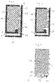
- figure 1 shows a refrigerator and/or freezer according to the invention.
- This device is designed as a built-in device and basically has the same structure as the device in accordance with figure 2 , so that reference is made accordingly. Parts that are the same or have the same function are given the same reference numbers as in figure 2 .
- the only difference to the structure according to figure 2 is that the fan 50 is arranged in the compressor niche.
- the fan 50 is arranged in such a way that the air L is conveyed from the compressor 30 and from the front inlet opening E through the duct K1, which are also located on the suction side of the fan 50. Like this out figure 1 shows, the air thus first flows along below the device body 10 and is then deflected vertically upwards. The air then flows through the vertical channel K2, in which the condenser 12 is located, and then exits through an opening O, which is located at the top and rear of the device or in the furniture unit 20.
- the device has a control or regulation unit, not shown, which is designed to operate the fan depending on the temperature of the condenser.
- the control or regulation unit is designed in such a way that an energetic optimum is achieved between the condenser temperature and the variable flow rate of the fan, and thus the energy consumption of the device is minimized.
- control or regulation unit is designed in such a way that it controls the fan 50 as a function of at least one parameter of the ambient conditions, the parameter or parameters including the ambient temperature.
- the control or regulation unit controls the fan 50 as a function of at least one parameter of the ambient conditions, the parameter or parameters including the ambient temperature.
- additional independent variables for example, the ambient air humidity, the light or solar radiation, the ambient pressure and/or the time of day can come into consideration.
- the device is designed so that under a given set of such conditions, operation with the fan 50 on or with the fan 50 off may be more appropriate.
- the fan 50 is arranged in such a way that air is guided over a container (not shown) for receiving condensed water, as a result of which the evaporation capacity is increased.
- the present invention lowers the condensing temperature and also enables operation without the fan running if it is not required.
- a further advantage of the invention is that the use of the fan or the air flow generated by it can counteract the formation of condensate on the outer surfaces of the device.
- air guiding elements In order to guide the air into these areas, air guiding elements can be provided.
Landscapes
- Engineering & Computer Science (AREA)
- Physics & Mathematics (AREA)
- Mechanical Engineering (AREA)
- Thermal Sciences (AREA)
- General Engineering & Computer Science (AREA)
- Chemical & Material Sciences (AREA)
- Combustion & Propulsion (AREA)
- Devices That Are Associated With Refrigeration Equipment (AREA)
- Physical Or Chemical Processes And Apparatus (AREA)
- Removal Of Water From Condensation And Defrosting (AREA)
Description
- Die vorliegende Erfindung betrifft eine Anordnung umfassend ein als Einbaugerät ausgestelltes Kühl- und/oder Gefriergerät sowie einen Möbelumbau, in dem das Gerät angeordnet ist, wobei das Kühl- und/oder Gefriergerät wenigstens einen Korpus und wenigstens einen von dem Korpus umgebenen gekühlten Innenraum umfasst, wobei das Gerät zumindest einen Kältemittelkreislauf aufweist, der wenigstens einen Verflüssiger umfasst, der sich an der Rückseite des Korpus in einem Luftkanal zwischen der Geräterückseite und dem Möbelumbau befindet, und wobei das Gerät wenigstens einen Ventilator aufweist, der so angeordnet ist, dass er im Betrieb eine Luftströmung über den Verflüssiger erzeugt.
- Aus dem Stand ist es bekannt, den Verflüssiger eines Kältemittelkreislaufes beispielsweise im Bereich der Rückseite des Gerätekorpus anzuordnen und mittels eines Ventilators eine Luftströmung über den Verflüssiger zu erzeugen. Exemplarisch wird auf die
DE 20 2005 059 490 A1 verwiesen. - Des Weiteren sind aus dem Stand der Technik Geräte bekannt, bei denen die Belüftung des Verflüssigers ausschließlich durch natürliche Konvektion erfolgt. Ein solches Gerät ist in
Figur 2 dargestellt. Bei diesem Gerät handelt es sich um ein Einbaugerät 10, das in einem Möbelumbau angeordnet ist, der mit dem Bezugszeichen 20 gekennzeichnet ist. Im rückseitigen Bereich des Gerätes 10 befindet sich der Verflüssiger 12 in einem Luftkanal zwischen der Geräterückseite und dem Möbelumbau 20. Das Bezugszeichen 30 kennzeichnet den Verdichter des Kältemittelkreislaufes. Dieser ist unterhalb des Verflüssigers 12 in der Kompressornische untergebracht. - Wie dies durch die Pfeile gekennzeichnet ist, tritt die Luft L vorne unter dem Gerät in den Möbelumbau 20 ein und steigt dann im Bereich der Kompressornische nach oben. Die Luft nimmt Wärme von der Hochdruckseite des Kältemittelkreislaufes auf, wobei die Hochdruckseite den Verdichter, den Verflüssiger und die Druckleitung zwischen Verdichter 30 und Verflüssiger 12 umfasst. Wie dies aus
Figur 2 hervorgeht, strömt die Luft dabei in einem Kanal zwischen der Geräterückwand und der Möbelrückwand bzw. einer Gebäudewand, vor der das Gerät steht, nach oben. Diese Luftbewegung erfolgt ausschließlich aufgrund natürlicher Konvektion. -
Figur 3 zeigt ein aus dem Stand der Technik bekanntes Beispiel für ein Standgerät mit einem unterhalb des gekühlten Innenraums bzw. des Korpus 40 verbauten Verflüssiger 12. Zwischen dem Verflüssiger 12 und dem Verdichter 30 befindet sich der Ventilator 45, der eine Luftströmung L erzeugt. Wie dies ausFigur 3 hervorgeht, sind der Verflüssiger 12 und der Verdichter 30 in der Kompressornische unter dem Korpus angeordnet. Die Luft wird von der Vorderseite des Gerätes im Bodenbereich über den Verflüssiger 12 angesaugt und dann über den Verdichter 30 und entlang der Geräterückwand nach oben gefördert. - Die
US 4 089 187 A offenbart eine Anordnung gemäß dem Oberbegriff des Anspruchs 1. DieCN 204 535 240 U offenbart ein Kältegerät, bei dem die Geschwindigkeit eines Verflüssigersventilators in Abhängigkeit der Temperatur des Kältemittels gesteuert wird. Weiterer relevanter Stand der Technik ist inCN 1 727 822 A undJP 2014 059109 A - Der vorliegenden Erfindung liegt die Aufgabe zugrunde, ein Kühl- und/oder Gefriergerät der eingangs genannten Art dahingehend weiterzubilden, dass dieses gegenüber bekannten Geräten energetische Vorteile aufweist.
- Diese Aufgabe wird durch eine Anordnung mit den Merkmalen des Anspruchs 1 gelöst.
- Danach ist vorgesehen, dass die Anordnung eine Steuereinheit umfasst, die ausgebildet ist, den Ventilator in Abhängigkeit weingstens eines Parameters der Umgebungsbedingungen anzusteuern.
- Die erfindungsgemäße Anordnung berücksichtigt also, dass bei bestimmten Umgebungsbedingungen ein Betrieb mit eingeschaltetem Ventilator energetisch oder anderweitig (z.B. betreffen Geräuschemission) sinnvoll sein kann, während bei anderen, veränderten Umgebungsbedingungen (Umgebungstemperatur, Umgebungsluftfeuchtigkeit, Licht- bzw. Sonneneinstrahlung, Umgebungsdruck, Tageszeit, etc.) ein Betrieb mit ausgeschaltetem Betrieb sinnvoller ist.
- Grundsätzlich wirkt sich eine Reduzierung der Verflüssigungstemperatur positiv auf den Energieverbrauch des Gerätes aus. Erfindungsgemäß ist es möglich, das Gerät auch mit ausgeschaltetem Ventilator zu betreiben, was in einer Geräuschminderung sowie in einem verringerten Energieverbrauch aufgrund des ausgeschalteten Ventilators resultiert. Dennoch erfolgt eine Kühlung des Verflüssigers durch natürliche Konvektion, wie dies beispielsweise bei dem aus dem Stand der Technik bekannten Gerät gemäß
Figur 2 bekannt ist. - Denkbar ist es, dass die natürliche Konvektionsströmung denselben Verlauf hat, wie in
Figur 2 dargestellt, d.h. vorne unten ein Eintritt der Luft erfolgt, diese dann nach oben umgelenkt wird und entlang der Rückseite über den Verflüssiger nach oben strömt. Grundsätzlich sind von der Erfindung auch beliebige andere Strömungswege umfasst. - Vorzugsweise weist der Weg der durch natürliche Konvektion bedingten Luftströmung denselben Verlauf auf, wie der durch den Ventilator bedingte erzwungene Luftstrom, d.h. die dynamische Belüftung.
- Eine luftdichte Trennung zwischen Hoch- und Niederdruckseite des Ventilators ist erfindungsgemäß nicht vorhanden, so dass ein Betrieb auch mit ausgeschaltetem Ventilator durch natürliche Konvektion möglich ist.
- Durch das Betreiben des Ventilators wird die natürliche Konvektion von Luft auf der Hochdruckseite des Kältemittelkreislaufes unterstützt. Dadurch ergibt sich eine bessere Wärmeübertragung in diesem Bereich und die Verflüssigungstemperatur sinkt. Dies wirkt sich positiv auf den Energieverbrauch des Gerätes aus. Wird der Ventilator nicht betrieben, ergeben sich die gleichen oder annähernd die gleichen Betriebsbedingungen wie bei dem aus dem Stand der Technik bekannten Gerät, z.B. gemäß
Figur 2 . - Die Luftführungen, die die durch den Ventilator geförderte Luft lenken, können so gestaltet werden, dass diese gleichzeitig als Aufnahme für den Ventilator und/oder für die Tauwasserverdunstungsschale dienen.
- Erfindungsgemäß ist der Ventilator derart ausgebildet, dass die durch diesen geförderte Luftmenge veränderbar ist. Denkbar ist es beispielsweise, dass der Ventilator drehzahlgeregelt ist, so dass dessen Leistung bzw. Förderleistung reguliert werden kann. Dies kann beispielsweise bei sich ändernden Umgebungsbedingungen, in Abhängigkeit vom Gerätezustand, dem zulässigen Geräuschpegel oder der gewünschten Geräteeffizienz der Fall sein.
- Somit kann der Ventilator mit einer adaptiven Fördermenge betrieben werden. Diese ist abhängig von der Wärmelast, die am Verflüssiger abgegeben werden soll sowie von äußeren Einflüssen, wie wenigstens von der Umgebungstemperatur.
- In einer bevorzugten Ausgestaltung der Erfindung ist vorgesehen, dass eine Steuerungs- oder Regelungseinheit vorhanden ist, die ausgebildet ist, die Fördermenge des Ventilators abhängig von der Temperatur des Verflüssigers einzustellen. Dabei ist es insbesondere von Vorteil, wenn die Steuer- oder Regelungseinheit ausgebildet ist, den Ventilator so zu betreiben, dass sich hinsichtlich des Energieverbrauchs des Gerätes ein Optimum ergibt. Wie oben ausgeführt, wirkt sich eine Reduzierung der Verflüssigungstemperatur, die durch eine höhere Förderrate des Ventilators erzeugt werden kann, positiv auf den Energieverbrauch des Gerätes aus. Eine höhere Drehzahl bzw. eine erhöhte Fördermenge des Ventilators ist allerdings mit einer höheren Leistungsaufnahme des Ventilators verbunden. Es existiert somit ein energetisches Optimum hinsichtlich der Leistungsaufnahme und dem Energieverbrauch des Kältemittelkreislaufes, bei dem der niedrigste Energieverbrauch erzielt wird.
- Die genannte Steuer- oder Regelungseinheit kann ausgeführt sein, den Ventilator so zu betreiben, dass dieses energetische Optimum bzw. ein bestimmter Bereich um dieses Optimum erreicht wird.
- Der Ventilator kann so angeordnet sein, dass er Luft über den Verflüssiger saugt oder bläst. Denkbar ist eine Anordnung, bei der der Ventilator Luft über den Verdichter saugt und über den Verflüssiger bläst.
- Denkbar ist es, den Ventilator in der Kompressornische des Gerätes anzuordnen. Dies hat den Vorteil, dass kein eigener Bauraum für den Ventilator benötigt wird.
- Die Anordnung weist wenigstens ein Behältnis zur Aufnahme von Tauwasser auf, wobei der Ventilator so angeordnet ist, dass er im Betrieb über das in dem Behältnis befindliche Tauwasser eine Luftströmung erzeugt.
- Durch diese Luftströmung wird die Verdunstung von Tauwasser gefördert.
- Erfindungsgemäß ist eine Einheit vorgesehen, die den Ventilator in Abhängigkeit der zu verdunstenden Wassermenge betreibt und zwar dahingehend, dass die Förderleistung und/oder -zeit des Ventilators je größer ist, desto mehr Tauwasser verdunstet werden muss. Somit kann der Ventilator beispielsweise so getaktet betrieben werden, dass im Bedarfsfall mehr Tauwasser verdunstet wird. Vorzugsweise kann durch diese Anordnung des Ventilators erreicht werden, dass keine Verdunstungsschalenheizung erforderlich ist.
- In einer weiteren Ausgestaltung der Erfindung ist vorgesehen, dass der Kältemittelkreislauf wenigstens einen Verdichter aufweist und dass der Ventilator so angeordnet ist, dass er im Betrieb über den Verdichter eine Luftströmung erzeugt. Somit kann eine Kühlung des Verdichters erreicht werden. Vorzugsweise erfolgt diese Kühlung mittels desselben Ventilators, der einen Luftstrom über den Verflüssiger erzeugt.
- Der Ventilator kann zwischen dem Verdichter und dem Verflüssiger angeordnet sein, so dass der Verdichter auf der Saugseite und der Verflüssiger auf der Druckseite des Ventilators angeordnet ist.
- Gemäß der Erfindung ist vorgesehen, dass es sich bei dem Gerät um ein Einbaugerät handelt.
- In einer weiteren Ausgestaltung der Erfindung weist das Gerät wenigstens eine frontseitige Öffnung auf, durch die die mittels des Ventilators geförderte Luft in den Luftkanal eintritt. Diese Luft strömt dann vorzugsweise unterhalb des gekühlten Innenraums bzw. unterhalb des Korpus entlang und dann nach oben über den Verflüssiger. Die Luft tritt dann oben z.B. an der Rückseite des Gerätes aus. Bevorzugt ist es, wenn der Ventilator bei höchsteffizienten Geräten zum Einsatz kommt, bei hocheffizienten Geräten jedoch nicht. So besteht die Möglichkeit, den gleichen Geräteaufbau für Geräte mit und ohne Ventilator bzw. Ventilatormodul zu verwenden, was Kostenvorteile mit sich bringt.
- In einer weiteren bevorzugten Ausgestaltung ist der Ventilator so angeordnet, dass gegenüber bekannten Geräten keine Änderung des Möbelumbaus erforderlich ist. So wird trotz des Einsatz eines Ventilators bzw. eines dynamisch belüfteten Verflüssigers keine Änderung des Möbelumbaus erforderlich. So kann in einer Ausführungsform weiterhin die Luftansaugung frontseitig wie in
Figur 2 beschrieben erfolgen. - Weitere Einzelheiten und Vorteile der Erfindung werden anhand eines in der Zeichnung dargestellten Ausführungsbeispiels näher erläutert. Es zeigen:
- Figur 1:
- eine schematische Ansicht eines Kühl- und/oder Gefriergerätes als Einbaugerät gemäß der Erfindung,
- Figur 2:
- eine schematische Ansicht eines Kühl- und/oder Gefriergerätes als Einbaugerät aus dem Stand der Technik und
- Figur 3:
- eine schematische Ansicht eines Kühl- und/oder Gefriergerätes als Standgerät aus dem Stand der Technik.
-
Figur 1 zeigt ein Kühl- und/oder Gefriergerät gemäß der Erfindung. Dieses Gerät ist als Einbaugerät ausgeführt und weist grundsätzlich denselben Aufbau auf, wie das Gerät gemäßFigur 2 , so dass entsprechend Bezug genommen wird. Gleiche oder funktionsgleiche Teile sind mit denselben Bezugszeichen versehen wie inFigur 2 . - Der einzige Unterschied zu dem Aufbau gemäß
Figur 2 besteht darin, dass in der Kompressornische der Ventilator 50 angeordnet ist. - Dieser ist so angeordnet, dass sich der Verdichter 30 auf der Saugseite des Ventilators 50 und der Verflüssiger 12 auf der Druckseite befindet.
- Der Ventilator 50 ist so angeordnet, das die Luft L von dem Verdichter 30 und von der frontseitigen Einlassöffnung E durch den Kanal K1 gefördert wird, die sich ebenfalls auf der Saugseite des Ventilators 50 befinden. Wie dies aus
Figur 1 hervorgeht, strömt die Luft somit zunächst entlang unterhalb des Gerätekorpus 10 und wird dann vertikal nach oben umgelenkt. Die Luft durchströmt dann den vertikalen Kanal K2, in dem sich der Verflüssiger 12 befindet und tritt anschließend durch eine Öffnung O aus, die sich oben und hinten am Gerät bzw. im Möbelumbau 20 befindet. - Das Gerät weist eine nicht dargestellte Steuer- oder Regelungseinheit auf, die ausgebildet ist, den Ventilator in Abhängigkeit von der Temperatur des Verflüssigers zu betreiben.
- Dabei ist die Steuer- oder Regelungseinheit so ausgebildet, dass zwischen der Verflüssigertemperatur und der variablen Fördermenge des Ventilators ein energetisches Optimum erzielt wird und somit der Energieverbrauch des Gerätes minimiert wird.
- Erfindungsgemäß ist die Steuer- oder Regelungseinheit so ausgebildet, dass sie den Ventilator 50 in Abhängigkeit weingstens eines Parameters der Umgebungsbedingungen ansteuert, wobei der oder die Parameter die Umgebungstemperatur umfassen. Als zusätzliche unabhängige Variablen können beispielsweise die Umgebungsluftfeuchtigkeit, die Licht- bzw. Sonneneinstrahlung, der Umgebungsdruck und/oder die Tageszeit in Frage kommen. Mithin ist das Gerät ausgebildet, dass bei einem bestimmten Satz an solchen Bedingungen ein Betrieb mit eingeschaltetem oder mit ausgeschaltetem Ventilator 50 sinnvoller sein kann.
- Der Ventilator 50 ist zudem so angeordnet, dass Luft über ein nicht dargestelltes Gefäß zur Aufnahme von Tauwasser geleitet wird, wodurch die Verdunstungsleistung erhöht wird.
- Durch die vorliegende Erfindung wird die Verflüssigungstemperatur gesenkt und zudem ein Betrieb ohne laufenden Ventilator ermöglicht, sofern dieser nicht benötigt wird.
- Ein weiterer Vorteil der Erfindung besteht darin, dass durch den Einsatz des Ventilators bzw. durch die durch diesen erzeugte Luftströmung der Bildung von Kondensat auf den Außenflächen des Gerätes entgegengewirkt werden kann.
- Somit kann auf eine Beheizung der zur Kondensation neigenden Außenflächen durch ein Heizelement verzichtet werden.
- Um die Luft in diese Bereiche zu lenken, können Luftleitelemente vorgesehen sein.
Claims (6)
- Anordnung umfassend ein als Einbaugerät ausgestaltetes Kühl- und/oder Gefriergerät sowie einen Möbelumbau (20), in dem das Gerät angeordnet ist, wobei das Kühl- und/oder Gefriergerät wenigstens einen Korpus (10) und wenigstens einen von dem Korpus (10) umgebenen gekühlten Innenraum umfasst, wobei das Gerät zumindest einen Kältemittelkreislauf aufweist, der wenigstens einen Verflüssiger (12) umfasst, der sich an der Rückseite des Korpus (10) in einem Luftkanal (K2) zwischen der Geräterückseite und dem Möbelumbau (20) befindet, und wobei das Gerät wenigstens einen Ventilator (50) aufweist, der so angeordnet ist, dass er im Betrieb eine Luftströmung (L) über den Verflüssiger (12) erzeugt, wobei bei ausgeschaltetem Ventilator (50) eine Luftströmung (L) über den Verflüssiger (12) durch natürliche Konvektion erfolgt, wobei der Ventilator (50) derart ausgebildet ist, dass die durch diesen geförderte Luftmenge (L) veränderbar ist,dadurch gekennzeichnet,dass das Gerätwenigstens ein Behältnis zur Aufnahme von Tauwasser aufweist, wobei der Ventilator (50) so angeordnet ist, dass er im Betrieb über das in dem Behältnis befindliche Tauwasser eine Luftströmung (L) erzeugt; undeine Steuereinheit umfasst, die ausgebildet ist, den Ventilator (50) in Abhängigkeit der zu verdunstenden Tauwassermenge und wenigstens eines Parameters der Umgebungsbedingungen anzusteuern, wobei der oder die Parameter die Umgebungstemperatur umfassen.
- Anordnung nach Anspruch 1, dadurch gekennzeichnet, dass eine Steuerungs- oder Regelungseinheit vorhanden ist, die ausgebildet ist, die Fördermenge des Ventilators (50) abhängig von der Temperatur des Verflüssigers (12) einzustellen.
- Anordnung nach einem der vorhergehenden Ansprüche, dadurch gekennzeichnet, dass der Ventilator (50) so angeordnet ist, dass er Luft (L) über den Verflüssiger (12) saugt oder bläst.
- Anordnung nach einem der vorhergehenden Ansprüche, dadurch gekennzeichnet, dass der Kältemittelkreislauf wenigstens einen Verdichter (30) aufweist und dass der Ventilator (50) so angeordnet ist, dass er im Betrieb über den Verdichter (30) eine Luftströmung (L) erzeugt.
- Anordnung nach Anspruch 4, dadurch gekennzeichnet, dass der Ventilator (50) zwischen dem Verdichter (30) und dem Verflüssiger (12) angeordnet ist.
- Anordnung nach einem der vorhergehenden Ansprüche, dadurch gekennzeichnet, dass das Gerät wenigstens eine frontseitige Öffnung (E) aufweist, durch die die mittels des Ventilators (50) geförderte Luft (L) eintritt.
Applications Claiming Priority (1)
| Application Number | Priority Date | Filing Date | Title |
|---|---|---|---|
| DE102016010444.9A DE102016010444A1 (de) | 2016-08-29 | 2016-08-29 | Kühl- und/oder Gefriergerät |
Publications (2)
| Publication Number | Publication Date |
|---|---|
| EP3290839A1 EP3290839A1 (de) | 2018-03-07 |
| EP3290839B1 true EP3290839B1 (de) | 2022-04-13 |
Family
ID=59713913
Family Applications (1)
| Application Number | Title | Priority Date | Filing Date |
|---|---|---|---|
| EP17188063.6A Not-in-force EP3290839B1 (de) | 2016-08-29 | 2017-08-28 | Kühl- und/oder gefriergerät |
Country Status (3)
| Country | Link |
|---|---|
| EP (1) | EP3290839B1 (de) |
| DE (1) | DE102016010444A1 (de) |
| ES (1) | ES2918005T3 (de) |
Citations (5)
| Publication number | Priority date | Publication date | Assignee | Title |
|---|---|---|---|---|
| EP0719995A2 (de) * | 1994-12-28 | 1996-07-03 | Kabushiki Kaisha Toshiba | Kühlschrank |
| CN1727822A (zh) * | 2004-07-26 | 2006-02-01 | 乐金电子(天津)电器有限公司 | 内置式冰箱的散热装置 |
| JP2009085455A (ja) * | 2007-09-28 | 2009-04-23 | Mitsubishi Electric Corp | 冷蔵庫 |
| US20090241567A1 (en) * | 2006-08-29 | 2009-10-01 | Bsh Bosch Und Siemens Hausgeraete Gmbh | Refrigerator with force-ventilation condenser |
| JP2014059109A (ja) * | 2012-09-18 | 2014-04-03 | Sharp Corp | 冷蔵庫 |
Family Cites Families (4)
| Publication number | Priority date | Publication date | Assignee | Title |
|---|---|---|---|---|
| US4089187A (en) * | 1975-06-23 | 1978-05-16 | General Electric Company | Condenser-air flow system of a household refrigerator |
| US6560980B2 (en) * | 2000-04-10 | 2003-05-13 | Thermo King Corporation | Method and apparatus for controlling evaporator and condenser fans in a refrigeration system |
| DE102005059490A1 (de) | 2005-12-08 | 2007-06-21 | Schmücker, Hartmut, Dr. | Luftkühlschacht zur Kühlung der Kälteaggregate von Kühl- und Gefriergeräten zum Einbau in eine (Möbel-) Nische |
| CN204535240U (zh) * | 2014-10-31 | 2015-08-05 | 合肥晶弘电器有限公司 | 一种风冷冰箱冷凝器散热系统及冰箱 |
-
2016
- 2016-08-29 DE DE102016010444.9A patent/DE102016010444A1/de not_active Withdrawn
-
2017
- 2017-08-28 ES ES17188063T patent/ES2918005T3/es active Active
- 2017-08-28 EP EP17188063.6A patent/EP3290839B1/de not_active Not-in-force
Patent Citations (5)
| Publication number | Priority date | Publication date | Assignee | Title |
|---|---|---|---|---|
| EP0719995A2 (de) * | 1994-12-28 | 1996-07-03 | Kabushiki Kaisha Toshiba | Kühlschrank |
| CN1727822A (zh) * | 2004-07-26 | 2006-02-01 | 乐金电子(天津)电器有限公司 | 内置式冰箱的散热装置 |
| US20090241567A1 (en) * | 2006-08-29 | 2009-10-01 | Bsh Bosch Und Siemens Hausgeraete Gmbh | Refrigerator with force-ventilation condenser |
| JP2009085455A (ja) * | 2007-09-28 | 2009-04-23 | Mitsubishi Electric Corp | 冷蔵庫 |
| JP2014059109A (ja) * | 2012-09-18 | 2014-04-03 | Sharp Corp | 冷蔵庫 |
Also Published As
| Publication number | Publication date |
|---|---|
| DE102016010444A1 (de) | 2018-03-01 |
| EP3290839A1 (de) | 2018-03-07 |
| ES2918005T3 (es) | 2022-07-13 |
Similar Documents
| Publication | Publication Date | Title |
|---|---|---|
| DE202005000560U1 (de) | Vorrichtung zum Kühlen von mobilen Wohn- und Arbeitsräumen | |
| EP3281505A1 (de) | Kühlgerät für die kühlung der im innenraum eines schaltschranks aufgenommenen luft und eine entsprechende schaltschrankanordnung | |
| DE102010013977A1 (de) | Kühlmöbel, Vorrichtung zum Regeln und/oder Steuern der Kühlung eines Kühlmöbels sowie Bausatz zum Umrüsten eines Kühlmöbels | |
| DE102017215488A1 (de) | Kältegerät mit mehreren Temperaturzonen | |
| EP2697578B1 (de) | Kältegerät mit verdunstungsschale | |
| DE102017002599A1 (de) | Kühl- und/oder Gefriergerät | |
| DE102019202649A1 (de) | Kältegerät | |
| DE102012108108B4 (de) | Schaltschrank mit einem Kühlgerät für die passive Schaltschrankkühlung | |
| DE102017213972A1 (de) | Kältegerät mit Verdunstungsschale | |
| EP0920830B1 (de) | Verfahren zur Geschirrtrocknung in einer elekrischen Haushaltsmaschine | |
| EP3290839B1 (de) | Kühl- und/oder gefriergerät | |
| EP3006863A1 (de) | Integriertes kühl-/klimaaggregat | |
| CH713485A2 (de) | Kühlgerät mit aktiv gekühltem Maschinenraum. | |
| EP3604988B1 (de) | Kühlgerät mit mehreren temperaturzonen | |
| DE202008000950U1 (de) | Wärmepumpe | |
| EP2837275B1 (de) | Kühlgerät für einen schaltschrank sowie ein entsprechendes verfahren | |
| DE202024002670U1 (de) | Kühlschrank | |
| AT504135B1 (de) | Verfahren zur wärmerückgewinnung | |
| DE102015101022B3 (de) | Rechenzentrum | |
| EP2612574A1 (de) | Kühlmöbel | |
| DE102010055726A1 (de) | Kühl- und/oder Gefriergerät | |
| EP2881687B1 (de) | Kühlgerät | |
| DE202013011876U1 (de) | Saugbagger zur pneumatischen Aufnahme von Sauggut | |
| DE102019112093A1 (de) | Kühl- und/oder Gefriergerät | |
| EP3447410B1 (de) | Kühl- und/oder gefriergerät mit ventilator |
Legal Events
| Date | Code | Title | Description |
|---|---|---|---|
| PUAI | Public reference made under article 153(3) epc to a published international application that has entered the european phase |
Free format text: ORIGINAL CODE: 0009012 |
|
| STAA | Information on the status of an ep patent application or granted ep patent |
Free format text: STATUS: THE APPLICATION HAS BEEN PUBLISHED |
|
| AK | Designated contracting states |
Kind code of ref document: A1 Designated state(s): AL AT BE BG CH CY CZ DE DK EE ES FI FR GB GR HR HU IE IS IT LI LT LU LV MC MK MT NL NO PL PT RO RS SE SI SK SM TR |
|
| AX | Request for extension of the european patent |
Extension state: BA ME |
|
| STAA | Information on the status of an ep patent application or granted ep patent |
Free format text: STATUS: REQUEST FOR EXAMINATION WAS MADE |
|
| 17P | Request for examination filed |
Effective date: 20180907 |
|
| STAA | Information on the status of an ep patent application or granted ep patent |
Free format text: STATUS: EXAMINATION IS IN PROGRESS |
|
| 17Q | First examination report despatched |
Effective date: 20191121 |
|
| GRAP | Despatch of communication of intention to grant a patent |
Free format text: ORIGINAL CODE: EPIDOSNIGR1 |
|
| STAA | Information on the status of an ep patent application or granted ep patent |
Free format text: STATUS: GRANT OF PATENT IS INTENDED |
|
| INTG | Intention to grant announced |
Effective date: 20211104 |
|
| GRAS | Grant fee paid |
Free format text: ORIGINAL CODE: EPIDOSNIGR3 |
|
| GRAA | (expected) grant |
Free format text: ORIGINAL CODE: 0009210 |
|
| STAA | Information on the status of an ep patent application or granted ep patent |
Free format text: STATUS: THE PATENT HAS BEEN GRANTED |
|
| AK | Designated contracting states |
Kind code of ref document: B1 Designated state(s): AL AT BE BG CH CY CZ DE DK EE ES FI FR GB GR HR HU IE IS IT LI LT LU LV MC MK MT NL NO PL PT RO RS SE SI SK SM TR |
|
| REG | Reference to a national code |
Ref country code: GB Ref legal event code: FG4D Free format text: NOT ENGLISH |
|
| REG | Reference to a national code |
Ref country code: CH Ref legal event code: EP |
|
| REG | Reference to a national code |
Ref country code: DE Ref legal event code: R096 Ref document number: 502017012949 Country of ref document: DE |
|
| REG | Reference to a national code |
Ref country code: IE Ref legal event code: FG4D Free format text: LANGUAGE OF EP DOCUMENT: GERMAN |
|
| REG | Reference to a national code |
Ref country code: AT Ref legal event code: REF Ref document number: 1483699 Country of ref document: AT Kind code of ref document: T Effective date: 20220515 |
|
| REG | Reference to a national code |
Ref country code: ES Ref legal event code: FG2A Ref document number: 2918005 Country of ref document: ES Kind code of ref document: T3 Effective date: 20220713 |
|
| REG | Reference to a national code |
Ref country code: LT Ref legal event code: MG9D |
|
| REG | Reference to a national code |
Ref country code: NL Ref legal event code: MP Effective date: 20220413 |
|
| PG25 | Lapsed in a contracting state [announced via postgrant information from national office to epo] |
Ref country code: NL Free format text: LAPSE BECAUSE OF FAILURE TO SUBMIT A TRANSLATION OF THE DESCRIPTION OR TO PAY THE FEE WITHIN THE PRESCRIBED TIME-LIMIT Effective date: 20220413 |
|
| PG25 | Lapsed in a contracting state [announced via postgrant information from national office to epo] |
Ref country code: SE Free format text: LAPSE BECAUSE OF FAILURE TO SUBMIT A TRANSLATION OF THE DESCRIPTION OR TO PAY THE FEE WITHIN THE PRESCRIBED TIME-LIMIT Effective date: 20220413 Ref country code: PT Free format text: LAPSE BECAUSE OF FAILURE TO SUBMIT A TRANSLATION OF THE DESCRIPTION OR TO PAY THE FEE WITHIN THE PRESCRIBED TIME-LIMIT Effective date: 20220816 Ref country code: NO Free format text: LAPSE BECAUSE OF FAILURE TO SUBMIT A TRANSLATION OF THE DESCRIPTION OR TO PAY THE FEE WITHIN THE PRESCRIBED TIME-LIMIT Effective date: 20220713 Ref country code: LT Free format text: LAPSE BECAUSE OF FAILURE TO SUBMIT A TRANSLATION OF THE DESCRIPTION OR TO PAY THE FEE WITHIN THE PRESCRIBED TIME-LIMIT Effective date: 20220413 Ref country code: HR Free format text: LAPSE BECAUSE OF FAILURE TO SUBMIT A TRANSLATION OF THE DESCRIPTION OR TO PAY THE FEE WITHIN THE PRESCRIBED TIME-LIMIT Effective date: 20220413 Ref country code: GR Free format text: LAPSE BECAUSE OF FAILURE TO SUBMIT A TRANSLATION OF THE DESCRIPTION OR TO PAY THE FEE WITHIN THE PRESCRIBED TIME-LIMIT Effective date: 20220714 Ref country code: FI Free format text: LAPSE BECAUSE OF FAILURE TO SUBMIT A TRANSLATION OF THE DESCRIPTION OR TO PAY THE FEE WITHIN THE PRESCRIBED TIME-LIMIT Effective date: 20220413 Ref country code: BG Free format text: LAPSE BECAUSE OF FAILURE TO SUBMIT A TRANSLATION OF THE DESCRIPTION OR TO PAY THE FEE WITHIN THE PRESCRIBED TIME-LIMIT Effective date: 20220713 |
|
| PGFP | Annual fee paid to national office [announced via postgrant information from national office to epo] |
Ref country code: IT Payment date: 20220831 Year of fee payment: 6 Ref country code: ES Payment date: 20220901 Year of fee payment: 6 Ref country code: DE Payment date: 20220829 Year of fee payment: 6 |
|
| PG25 | Lapsed in a contracting state [announced via postgrant information from national office to epo] |
Ref country code: RS Free format text: LAPSE BECAUSE OF FAILURE TO SUBMIT A TRANSLATION OF THE DESCRIPTION OR TO PAY THE FEE WITHIN THE PRESCRIBED TIME-LIMIT Effective date: 20220413 Ref country code: PL Free format text: LAPSE BECAUSE OF FAILURE TO SUBMIT A TRANSLATION OF THE DESCRIPTION OR TO PAY THE FEE WITHIN THE PRESCRIBED TIME-LIMIT Effective date: 20220413 Ref country code: LV Free format text: LAPSE BECAUSE OF FAILURE TO SUBMIT A TRANSLATION OF THE DESCRIPTION OR TO PAY THE FEE WITHIN THE PRESCRIBED TIME-LIMIT Effective date: 20220413 Ref country code: IS Free format text: LAPSE BECAUSE OF FAILURE TO SUBMIT A TRANSLATION OF THE DESCRIPTION OR TO PAY THE FEE WITHIN THE PRESCRIBED TIME-LIMIT Effective date: 20220813 |
|
| PGFP | Annual fee paid to national office [announced via postgrant information from national office to epo] |
Ref country code: FR Payment date: 20220824 Year of fee payment: 6 |
|
| REG | Reference to a national code |
Ref country code: DE Ref legal event code: R097 Ref document number: 502017012949 Country of ref document: DE |
|
| PG25 | Lapsed in a contracting state [announced via postgrant information from national office to epo] |
Ref country code: SM Free format text: LAPSE BECAUSE OF FAILURE TO SUBMIT A TRANSLATION OF THE DESCRIPTION OR TO PAY THE FEE WITHIN THE PRESCRIBED TIME-LIMIT Effective date: 20220413 Ref country code: SK Free format text: LAPSE BECAUSE OF FAILURE TO SUBMIT A TRANSLATION OF THE DESCRIPTION OR TO PAY THE FEE WITHIN THE PRESCRIBED TIME-LIMIT Effective date: 20220413 Ref country code: RO Free format text: LAPSE BECAUSE OF FAILURE TO SUBMIT A TRANSLATION OF THE DESCRIPTION OR TO PAY THE FEE WITHIN THE PRESCRIBED TIME-LIMIT Effective date: 20220413 Ref country code: EE Free format text: LAPSE BECAUSE OF FAILURE TO SUBMIT A TRANSLATION OF THE DESCRIPTION OR TO PAY THE FEE WITHIN THE PRESCRIBED TIME-LIMIT Effective date: 20220413 Ref country code: DK Free format text: LAPSE BECAUSE OF FAILURE TO SUBMIT A TRANSLATION OF THE DESCRIPTION OR TO PAY THE FEE WITHIN THE PRESCRIBED TIME-LIMIT Effective date: 20220413 Ref country code: CZ Free format text: LAPSE BECAUSE OF FAILURE TO SUBMIT A TRANSLATION OF THE DESCRIPTION OR TO PAY THE FEE WITHIN THE PRESCRIBED TIME-LIMIT Effective date: 20220413 |
|
| PLBE | No opposition filed within time limit |
Free format text: ORIGINAL CODE: 0009261 |
|
| STAA | Information on the status of an ep patent application or granted ep patent |
Free format text: STATUS: NO OPPOSITION FILED WITHIN TIME LIMIT |
|
| 26N | No opposition filed |
Effective date: 20230116 |
|
| PG25 | Lapsed in a contracting state [announced via postgrant information from national office to epo] |
Ref country code: MC Free format text: LAPSE BECAUSE OF FAILURE TO SUBMIT A TRANSLATION OF THE DESCRIPTION OR TO PAY THE FEE WITHIN THE PRESCRIBED TIME-LIMIT Effective date: 20220413 Ref country code: AL Free format text: LAPSE BECAUSE OF FAILURE TO SUBMIT A TRANSLATION OF THE DESCRIPTION OR TO PAY THE FEE WITHIN THE PRESCRIBED TIME-LIMIT Effective date: 20220413 |
|
| REG | Reference to a national code |
Ref country code: CH Ref legal event code: PL |
|
| GBPC | Gb: european patent ceased through non-payment of renewal fee |
Effective date: 20220828 |
|
| PG25 | Lapsed in a contracting state [announced via postgrant information from national office to epo] |
Ref country code: LU Free format text: LAPSE BECAUSE OF NON-PAYMENT OF DUE FEES Effective date: 20220828 Ref country code: LI Free format text: LAPSE BECAUSE OF NON-PAYMENT OF DUE FEES Effective date: 20220831 Ref country code: CH Free format text: LAPSE BECAUSE OF NON-PAYMENT OF DUE FEES Effective date: 20220831 |
|
| REG | Reference to a national code |
Ref country code: BE Ref legal event code: MM Effective date: 20220831 |
|
| PG25 | Lapsed in a contracting state [announced via postgrant information from national office to epo] |
Ref country code: SI Free format text: LAPSE BECAUSE OF FAILURE TO SUBMIT A TRANSLATION OF THE DESCRIPTION OR TO PAY THE FEE WITHIN THE PRESCRIBED TIME-LIMIT Effective date: 20220413 |
|
| PG25 | Lapsed in a contracting state [announced via postgrant information from national office to epo] |
Ref country code: IE Free format text: LAPSE BECAUSE OF NON-PAYMENT OF DUE FEES Effective date: 20220828 |
|
| PG25 | Lapsed in a contracting state [announced via postgrant information from national office to epo] |
Ref country code: BE Free format text: LAPSE BECAUSE OF NON-PAYMENT OF DUE FEES Effective date: 20220831 |
|
| REG | Reference to a national code |
Ref country code: AT Ref legal event code: MM01 Ref document number: 1483699 Country of ref document: AT Kind code of ref document: T Effective date: 20220828 |
|
| PG25 | Lapsed in a contracting state [announced via postgrant information from national office to epo] |
Ref country code: GB Free format text: LAPSE BECAUSE OF NON-PAYMENT OF DUE FEES Effective date: 20220828 Ref country code: AT Free format text: LAPSE BECAUSE OF NON-PAYMENT OF DUE FEES Effective date: 20220828 |
|
| REG | Reference to a national code |
Ref country code: DE Ref legal event code: R119 Ref document number: 502017012949 Country of ref document: DE |
|
| PG25 | Lapsed in a contracting state [announced via postgrant information from national office to epo] |
Ref country code: HU Free format text: LAPSE BECAUSE OF FAILURE TO SUBMIT A TRANSLATION OF THE DESCRIPTION OR TO PAY THE FEE WITHIN THE PRESCRIBED TIME-LIMIT; INVALID AB INITIO Effective date: 20170828 |
|
| PG25 | Lapsed in a contracting state [announced via postgrant information from national office to epo] |
Ref country code: CY Free format text: LAPSE BECAUSE OF FAILURE TO SUBMIT A TRANSLATION OF THE DESCRIPTION OR TO PAY THE FEE WITHIN THE PRESCRIBED TIME-LIMIT Effective date: 20220413 |
|
| PG25 | Lapsed in a contracting state [announced via postgrant information from national office to epo] |
Ref country code: MK Free format text: LAPSE BECAUSE OF FAILURE TO SUBMIT A TRANSLATION OF THE DESCRIPTION OR TO PAY THE FEE WITHIN THE PRESCRIBED TIME-LIMIT Effective date: 20220413 |
|
| PG25 | Lapsed in a contracting state [announced via postgrant information from national office to epo] |
Ref country code: IT Free format text: LAPSE BECAUSE OF NON-PAYMENT OF DUE FEES Effective date: 20230828 Ref country code: FR Free format text: LAPSE BECAUSE OF NON-PAYMENT OF DUE FEES Effective date: 20230831 Ref country code: DE Free format text: LAPSE BECAUSE OF NON-PAYMENT OF DUE FEES Effective date: 20240301 |
|
| PG25 | Lapsed in a contracting state [announced via postgrant information from national office to epo] |
Ref country code: MT Free format text: LAPSE BECAUSE OF FAILURE TO SUBMIT A TRANSLATION OF THE DESCRIPTION OR TO PAY THE FEE WITHIN THE PRESCRIBED TIME-LIMIT Effective date: 20220413 |
|
| REG | Reference to a national code |
Ref country code: ES Ref legal event code: FD2A Effective date: 20241001 |
|
| PG25 | Lapsed in a contracting state [announced via postgrant information from national office to epo] |
Ref country code: ES Free format text: LAPSE BECAUSE OF NON-PAYMENT OF DUE FEES Effective date: 20230829 |
|
| PG25 | Lapsed in a contracting state [announced via postgrant information from national office to epo] |
Ref country code: ES Free format text: LAPSE BECAUSE OF NON-PAYMENT OF DUE FEES Effective date: 20230829 |
|
| PG25 | Lapsed in a contracting state [announced via postgrant information from national office to epo] |
Ref country code: BG Free format text: LAPSE BECAUSE OF FAILURE TO SUBMIT A TRANSLATION OF THE DESCRIPTION OR TO PAY THE FEE WITHIN THE PRESCRIBED TIME-LIMIT Effective date: 20220413 |
|
| PG25 | Lapsed in a contracting state [announced via postgrant information from national office to epo] |
Ref country code: BG Free format text: LAPSE BECAUSE OF FAILURE TO SUBMIT A TRANSLATION OF THE DESCRIPTION OR TO PAY THE FEE WITHIN THE PRESCRIBED TIME-LIMIT Effective date: 20220413 |
|
| PG25 | Lapsed in a contracting state [announced via postgrant information from national office to epo] |
Ref country code: TR Free format text: LAPSE BECAUSE OF FAILURE TO SUBMIT A TRANSLATION OF THE DESCRIPTION OR TO PAY THE FEE WITHIN THE PRESCRIBED TIME-LIMIT Effective date: 20220413 |