EP3290891A1 - Verfahren und vorrichtung zur charakterisierung der abbildungsfehler eines optischen systems - Google Patents
Verfahren und vorrichtung zur charakterisierung der abbildungsfehler eines optischen systems Download PDFInfo
- Publication number
- EP3290891A1 EP3290891A1 EP17187915.8A EP17187915A EP3290891A1 EP 3290891 A1 EP3290891 A1 EP 3290891A1 EP 17187915 A EP17187915 A EP 17187915A EP 3290891 A1 EP3290891 A1 EP 3290891A1
- Authority
- EP
- European Patent Office
- Prior art keywords
- image
- optical
- aberration
- images
- aberrations
- Prior art date
- Legal status (The legal status is an assumption and is not a legal conclusion. Google has not performed a legal analysis and makes no representation as to the accuracy of the status listed.)
- Granted
Links
Images


Classifications
-
- G—PHYSICS
- G01—MEASURING; TESTING
- G01M—TESTING STATIC OR DYNAMIC BALANCE OF MACHINES OR STRUCTURES; TESTING OF STRUCTURES OR APPARATUS, NOT OTHERWISE PROVIDED FOR
- G01M11/00—Testing of optical apparatus; Testing structures by optical methods not otherwise provided for
- G01M11/02—Testing optical properties
- G01M11/0242—Testing optical properties by measuring geometrical properties or aberrations
- G01M11/0257—Testing optical properties by measuring geometrical properties or aberrations by analyzing the image formed by the object to be tested
- G01M11/0264—Testing optical properties by measuring geometrical properties or aberrations by analyzing the image formed by the object to be tested by using targets or reference patterns
-
- G—PHYSICS
- G01—MEASURING; TESTING
- G01J—MEASUREMENT OF INTENSITY, VELOCITY, SPECTRAL CONTENT, POLARISATION, PHASE OR PULSE CHARACTERISTICS OF INFRARED, VISIBLE OR ULTRAVIOLET LIGHT; COLORIMETRY; RADIATION PYROMETRY
- G01J3/00—Spectrometry; Spectrophotometry; Monochromators; Measuring colours
- G01J3/02—Details
- G01J3/0297—Constructional arrangements for removing other types of optical noise or for performing calibration
-
- G—PHYSICS
- G01—MEASURING; TESTING
- G01J—MEASUREMENT OF INTENSITY, VELOCITY, SPECTRAL CONTENT, POLARISATION, PHASE OR PULSE CHARACTERISTICS OF INFRARED, VISIBLE OR ULTRAVIOLET LIGHT; COLORIMETRY; RADIATION PYROMETRY
- G01J3/00—Spectrometry; Spectrophotometry; Monochromators; Measuring colours
- G01J3/28—Investigating the spectrum
-
- G—PHYSICS
- G01—MEASURING; TESTING
- G01J—MEASUREMENT OF INTENSITY, VELOCITY, SPECTRAL CONTENT, POLARISATION, PHASE OR PULSE CHARACTERISTICS OF INFRARED, VISIBLE OR ULTRAVIOLET LIGHT; COLORIMETRY; RADIATION PYROMETRY
- G01J3/00—Spectrometry; Spectrophotometry; Monochromators; Measuring colours
- G01J3/28—Investigating the spectrum
- G01J3/2823—Imaging spectrometer
-
- G—PHYSICS
- G01—MEASURING; TESTING
- G01M—TESTING STATIC OR DYNAMIC BALANCE OF MACHINES OR STRUCTURES; TESTING OF STRUCTURES OR APPARATUS, NOT OTHERWISE PROVIDED FOR
- G01M11/00—Testing of optical apparatus; Testing structures by optical methods not otherwise provided for
- G01M11/02—Testing optical properties
- G01M11/0207—Details of measuring devices
-
- G—PHYSICS
- G01—MEASURING; TESTING
- G01M—TESTING STATIC OR DYNAMIC BALANCE OF MACHINES OR STRUCTURES; TESTING OF STRUCTURES OR APPARATUS, NOT OTHERWISE PROVIDED FOR
- G01M11/00—Testing of optical apparatus; Testing structures by optical methods not otherwise provided for
- G01M11/02—Testing optical properties
- G01M11/0292—Testing optical properties of objectives by measuring the optical modulation transfer function
-
- G—PHYSICS
- G01—MEASURING; TESTING
- G01J—MEASUREMENT OF INTENSITY, VELOCITY, SPECTRAL CONTENT, POLARISATION, PHASE OR PULSE CHARACTERISTICS OF INFRARED, VISIBLE OR ULTRAVIOLET LIGHT; COLORIMETRY; RADIATION PYROMETRY
- G01J3/00—Spectrometry; Spectrophotometry; Monochromators; Measuring colours
- G01J3/28—Investigating the spectrum
- G01J3/2823—Imaging spectrometer
- G01J2003/2826—Multispectral imaging, e.g. filter imaging
Definitions
- the present invention relates to a method for characterizing at least one aberration of an optical system of an image acquisition device, able to acquire at least two images according to a field of view, the second image having a differential aberration with respect to the first.
- the invention also relates to an associated device and computer program.
- the invention is in the field of active optics, consisting in measuring and compensating optical defects, also called aberrations, in image acquisition devices.
- the invention proposes a method for characterizing at least one optical aberration of an optical system of an image acquisition device, the optical system having an associated optical transfer function depending on the aberrations, the acquisition device being able to acquire at least two images in a field of taken to introduce a differential aberration between the two images, each image being defined by a digital image signal.
- the method of the invention makes it possible to estimate the optical aberrations of an image acquisition device from two or more images having a known or estimated difference in aberration.
- the method of the invention applies for images for which the impact of the additional aberration is relatively small and imperceptible for a user. Such an acquisition of images can be carried out, in some cases, without modification of the image acquisition device.
- the method according to the invention may have one or more of the features below.
- the optical system to be characterized comprises at least one set of staggered detector arrays, and said first and second images belong to overlapping areas between adjacent detector arrays.
- the optical system comprises a plurality of sets of detector arrays, each set of detector arrays having an associated acquisition spectral band, the method being applied to all the overlap zones of the different spectral bands corresponding to the same zone. of the field of view, to determine aberrations relative to each of these areas of the field of view.
- the method is applied to at least one overlap zone of each spectral band, so as to characterize spectral band optical aberrations.
- the functional also depends on a spatial shift between the first image and the second image acquired, said spatial shift being estimated during the minimization of said functional.
- the step of calculating at least one parameter characterizing at least one optical aberration implements a modeling of said optical transfer function as a function of at least one coefficient of a decomposition in a base of Zernike polynomials of a wavefront error associated with the optical system of the acquisition device.
- the minimization of the functional is carried out by an iterative estimation method.
- the differential aberration value between the first and second acquired image is estimated during the minimization of said functional.
- the differential aberration between the first image and the second image is a relative defocus between the first image and the second image.
- said functional being also expressed as a function of a modeling of the optical transfer functions associated with the two acquisitions depending on the optical aberration (s) to be characterized as well as the differential aberration.
- the invention relates to a computer program comprising software instructions which, when implemented by a programmable device, implement a method for characterizing at least one optical aberration of a system.
- optical image acquisition device as briefly described above.
- the method of the invention applies in the field of satellite imagery but is not limited to this field. It will be described hereinafter in its application to satellite imagery for complex scene observation, for example in the context of satellite Earth observation, it being understood that the method is applicable for the acquisition of any other type of image.
- the figure 1 schematically illustrates an image acquisition device 10 used in one embodiment of the invention.
- the image acquisition device 10 comprises an optical system 12, comprising an imaging optic 14, for example one or more lenses and one or more detectors 16 able to capture electromagnetic waves forming a light signal representative of a scene, for example a landscape, and to transform it into an electrical signal.
- the optical system is capable of capturing one or more light signals, each belonging to a spectral band defined by a given wavelength interval.
- the optical system 12 includes a plurality of one-dimensional arrays of detectors, also called detector arrays.
- the optical system is capable of capturing several signals belonging to different spectral bands. It is in this case a multi-spectral optical system.
- the optical system 12 is associated with a digitization module 18, making it possible to transform the electrical signal into a digital image signal sampled on a two-dimensional sampling grid.
- a digital image signal is represented by a matrix of pixels, each pixel having a spatial position in the sampling grid and an associated radiometry value (or intensity).
- Such a representation of the digital image is called representation in the spatial domain.
- FIG. figure 3 Two sets of overlapping zones, denoted respectively ZR 1 and ZR 2 , are represented in FIG. figure 3 .
- the image acquisition device 10 is connected, by any appropriate connection means, for example via a data transmission bus, to a processing device 20, provided with one or more processors, and able to implement programs comprising software instructions capable of implementing the method for characterizing optical aberrations according to the invention.
- the processing device 20 comprises a module 22 for receiving digital images from the image acquisition device 10 and a module 24 for processing the digital images received.
- the processing device 20 also comprises a module 26 for estimating the optical aberrations sought by minimizing a function depending on two images acquired with a differential aberration.
- An unrepresented satellite, having a displacement trajectory T, is provided with an image acquisition device comprising an optical system 30.
- the image acquisition device 30 has, in the inter-array overlap areas, a differential aberration, for example a relative defocusing.
- the figure 3 schematically illustrates a sectional view of the sensor strips in an image acquisition device as described above.
- Each set of bars 40 i has one or more inter-bar overlap areas, as illustrated in FIG. figure 3 where the zones ZR 1 and ZR 2 are observed.
- a native focusing differential also called offset
- this offset is estimated and used in the method of characterizing optical aberrations as explained in detail below.
- a focus shift between the focal planes of two sets of strips 40 i and 40 j , in the inter-strip overlap areas, is estimated and used in the method of characterizing optical aberrations. as explained in detail below.
- a differential aberration value other than relative defocusing is intentionally introduced between sets of selected bars.
- the determination of optical aberrations exploits only the overlapping areas of each spectral band, exploiting the differential aberration existing between images acquired by the even and odd bars.
- the determination of the optical aberrations is carried out by overlap zone, which advantageously makes it possible to characterize the optical aberrations according to their spatial position in the field of view.
- the exploitation of the overlapping zones of each spectral band makes it possible to characterize the optical aberrations with a spatial and spectral location in the field of view of the image acquisition device.
- any optical system is characterized by an optical transfer function, which is the Fourier transform of the optical impulse response or PSF (Point Spread Function).
- optical transfer function characterizes the blur introduced by the optical system, thus the attenuation of spatial frequencies.
- the ideal optical transfer function also called optical diffraction transfer function characterizes the blur introduced in the absence of defects in the realization of the optical combination.
- optical aberrations are introduced by the optical system, and therefore the actual optical transfer function is different from the optical diffraction transfer function.
- sampling is usually accompanied by spectrum aliasing if Shannon's condition is not satisfied.
- h opt is the optical impulse response
- h det is the impulse response of the detector, associated with the integration of photons by an elementary detector and the possible displacement of the detector part of the image acquisition device during the integration time.
- An attempt is made to solve the phase diversity problem of estimating the wavefront error by using at least two images acquired on the same landscape with differential optical aberration.
- the resolution of the phase diversity problem is based on a modeling, according to the convolutional image acquisition model, of the pair of observed images, denoted I 1 and I 2 , as a function of the desired aberrations, themselves represented under the form of a combination of Zernike polynomials, the unknowns being the weights a i of this combination defined below.
- the value ⁇ aberr is associated with the additional differential aberration, introduced or estimated, between the two images I 1 and I 2 .
- the terms b 1 and b 2 denote the noise corresponding to the respective images I 1 , I 2 .
- ⁇ rep indicates the possible presence of aliasing in the frequency domain, also called spectral aliasing.
- spectral aliasing The phenomenon of spectral folding is known.
- WFE WFE a_priori + ⁇ i ⁇ I at i Z i
- Z i is the Zernike polynomial of index i, and has i corresponding decomposition coefficients (or weights).
- Each Zernike polynomial is associated with a type of optical aberration, for example Z 4 represents the focusing error, commonly called defocus, Z 5 and Z 6, two types of astigmatism, and so on.
- the number of indices in is any, for example between 1 and 40.
- Each value of coefficient a i of the decomposition (EQ5) is representative of the corresponding aberration in the image considered.
- the value of the coefficient a 4 is representative of the focusing error, it represents the mean squared error due to the defocusing.
- the invention proposes to use an acquisition of a pair of digital images I 1 , I 2 representative of the same portion of scene S, and having a differential aberration of value ⁇ aberr, by for example, a focusing difference ⁇ aberr, which is determined by construction or estimation.
- the invention proposes to minimize a func functional , obtained from the relations (EQ7) and (EQ8), which does not require the knowledge of the signal S, nor of the transfer function specific to the detectors FTM det .
- ⁇ 2 is the variance of the radiometric noise b average of each of the two images
- f x and f y represent the spatial frequencies
- ⁇ a correction term avoiding the numerical instabilities for the frequencies making the denominator close to 0.
- ⁇ can take the value 10 -12 .
- the use of the parameter ⁇ 2 is optional since the criterion of stopping the minimization of the functional relates to the relative value of the functional between two iterations. Nevertheless, the availability of such a model advantageously makes it possible to eliminate the images are too noisy and provides a confidence index on the estimate, a good estimate corresponding to a final functional value close to 1.
- the expression (EQ9) of the functional function Fonc to be minimized does not include the terms TF (S) and FTM det which are not known.
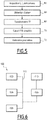
- the figure 4 is a logic diagram of the main steps of a method for characterizing optical aberrations according to a first embodiment of the invention.
- a first step 50 images, respectively a first image I 1 and a second image I 2 , having a differential aberration and corresponding to the same scene, are obtained from an image acquisition device.
- this differential aberration is present in the image acquisition device, for example in the inter-array overlap areas in the case of an image acquisition device. as described in figure 3 .
- a differential aberration is intentionally introduced, and the corresponding ⁇ aberr value is therefore known.
- the second image I 2 obtained is in this case not usable by a user application, except in the multispectral case mentioned above.
- the differential aberration is a defocusing
- the second image I 2 has a large amount of blur.
- step 52 an initial ⁇ aberr value of differential aberration is obtained, a refined value being obtained in step d subsequent estimate described below.
- a Fourier transform is then applied in a transformation step 56 to the image signals to obtain a first transformed image signal TF ( I 1 ) and a second transformed image signal TF ( I 2 ).
- the transformation step 56 is followed by a modeling step 58 of the module of the optical transfer function.
- P (x, y) is the binary mask which is 1 on the pupil and 0 elsewhere.
- phase term ⁇ ( x, y ), also called the aberrant phase, represents the difference at the point (x, y) between the phase of the real light wave on the pupillary plane and the phase of an ideal spherical wave.
- ⁇ is the centroid wavelength of the spectral band under consideration.
- Each coefficient value a i of the decomposition is representative of the corresponding aberration.
- step 60 implements an iterative estimate, by changing the respective values of the coefficients a i to minimize the func functional .
- an iterative estimate by changing the respective values of the coefficients a i to minimize the func functional .
- the stop criterion of the iterations relates to the relative value of the functional between two iterations: the convergence is considered reached when this relative value is lower than a predetermined threshold.
- the centroid wavelength ⁇ and the spatial offset between the two images I 1 are also estimated.
- I 2 represented by the term RP 2/1 in equation (EQ4), which are also unknowns, starting from predetermined initial values.
- the ⁇ aberr value of the differential aberration is also estimated during the iterative estimation step in step 60.
- Steps 62 to 68 are analogous to steps 50 to 56 of the first embodiment and are not described in more detail here.
- the step of applying a Fourier transform 68 is followed by a step of calculating the modules of the respective optical transfer functions denoted FTM opt and FTM opt + ⁇ aberr based on a simplification of the formulas applicable when the aberrant phase ⁇ (x, y) associated with the representation of the complex pupillary function is of low amplitude.
- optical transfer function can then be written in the form of a limited development: FTM Opt ⁇ FTM Opt WFE a priori + ⁇ i ⁇ The ⁇ i at i + ⁇ k , l ⁇ The ⁇ kl at k at l
- FTM opt WFE a priori
- ⁇ a i ⁇ are the coefficients of the decomposition of the wavefront error on the Based on the Zernike polynomials
- L is the subset of the indices of the Zernike polynomials to represent the aberrant phase
- ⁇ ⁇ i ⁇ , ⁇ ⁇ kl ⁇ are frequency functions.
- Expression (EQ14) or expression (EQ15) is used in the expression of the functional to be minimized.
- the value of a 4 obtained is then used in a subsequent step of use, for example to correct the setting of the shooting focus, or to finely deconvolve the image I 2 by algorithmic processing.
- the device 100 comprises control means 104 for updating parameters and receiving commands from an operator.
- the control means 104 comprise a telecommunication device for receiving remote commands and parameter values.
- control means 104 are means for inputting commands from an operator, for example a keyboard.
- the programmable device 100 comprises a screen 102 and additional pointing means 106, such as a mouse.
- the various functional blocks of the device 100 described above are connected via a communication bus 112.
- the device 100 is an ASIC, an FPGA, or a processor.
- a system for characterizing the aberrations of an optical system of an image acquisition device comprises an image acquisition device, such as the image acquisition device 10 of the figure 1 and a device adapted to implement the method for characterizing the aberrations of an optical system as described above.
- the method of the invention described above makes it possible to obtain the characterization of optical aberrations with a differential aberration value, for example a native focusing offset or introduced voluntarily.
Landscapes
- Physics & Mathematics (AREA)
- General Physics & Mathematics (AREA)
- Spectroscopy & Molecular Physics (AREA)
- Chemical & Material Sciences (AREA)
- Analytical Chemistry (AREA)
- Geometry (AREA)
- Image Processing (AREA)
- Studio Devices (AREA)
- Testing Of Optical Devices Or Fibers (AREA)
Applications Claiming Priority (1)
| Application Number | Priority Date | Filing Date | Title |
|---|---|---|---|
| FR1658275A FR3055727B1 (fr) | 2016-09-06 | 2016-09-06 | Procede et dispositif de caracterisation des aberrations d'un systeme optique |
Publications (3)
| Publication Number | Publication Date |
|---|---|
| EP3290891A1 true EP3290891A1 (de) | 2018-03-07 |
| EP3290891B1 EP3290891B1 (de) | 2024-08-28 |
| EP3290891C0 EP3290891C0 (de) | 2024-08-28 |
Family
ID=58054184
Family Applications (1)
| Application Number | Title | Priority Date | Filing Date |
|---|---|---|---|
| EP17187915.8A Active EP3290891B1 (de) | 2016-09-06 | 2017-08-25 | Verfahren und vorrichtung zur charakterisierung der abbildungsfehler eines optischen systems |
Country Status (4)
| Country | Link |
|---|---|
| US (1) | US10288523B2 (de) |
| EP (1) | EP3290891B1 (de) |
| CA (1) | CA2976931C (de) |
| FR (1) | FR3055727B1 (de) |
Cited By (1)
| Publication number | Priority date | Publication date | Assignee | Title |
|---|---|---|---|---|
| CN119935511A (zh) * | 2025-04-07 | 2025-05-06 | 南京施密特光学仪器有限公司 | 一种用于主次镜光学系统的波前误差检测方法 |
Families Citing this family (5)
| Publication number | Priority date | Publication date | Assignee | Title |
|---|---|---|---|---|
| CN109933882B (zh) * | 2019-03-07 | 2022-12-13 | 中国科学院紫金山天文台 | 环形主镜自由振动模态像差表征方法 |
| FR3104744B1 (fr) * | 2019-12-17 | 2023-04-14 | Thales Sa | Instrument d'observation optique embarque a resolution spatiale et spectrale variables |
| CN111650747B (zh) * | 2020-05-20 | 2021-04-20 | 中国科学院西安光学精密机械研究所 | 平行光管离焦像差实时校正方法及装置 |
| CN116280256A (zh) * | 2023-03-31 | 2023-06-23 | 北京航空航天大学 | 一种用于近地轨道空间碎片监测的微纳卫星 |
| CN118276313B (zh) * | 2024-05-30 | 2024-08-13 | 清华大学 | 大口径光学系统像差建模方法与矫正系统 |
Citations (2)
| Publication number | Priority date | Publication date | Assignee | Title |
|---|---|---|---|---|
| US20040052426A1 (en) * | 2002-09-12 | 2004-03-18 | Lockheed Martin Corporation | Non-iterative method and system for phase retrieval |
| FR2994488A1 (fr) * | 2012-08-07 | 2014-02-14 | Centre Nat Etd Spatiales | Procede d'estimation de l'etat de focalisation d'un instrument optique |
Family Cites Families (2)
| Publication number | Priority date | Publication date | Assignee | Title |
|---|---|---|---|---|
| US8494845B2 (en) * | 2006-02-16 | 2013-07-23 | Nippon Telegraph And Telephone Corporation | Signal distortion elimination apparatus, method, program, and recording medium having the program recorded thereon |
| US8490034B1 (en) * | 2010-07-08 | 2013-07-16 | Gauda, Inc. | Techniques of optical proximity correction using GPU |
-
2016
- 2016-09-06 FR FR1658275A patent/FR3055727B1/fr active Active
-
2017
- 2017-08-22 CA CA2976931A patent/CA2976931C/fr active Active
- 2017-08-24 US US15/685,832 patent/US10288523B2/en active Active
- 2017-08-25 EP EP17187915.8A patent/EP3290891B1/de active Active
Patent Citations (2)
| Publication number | Priority date | Publication date | Assignee | Title |
|---|---|---|---|---|
| US20040052426A1 (en) * | 2002-09-12 | 2004-03-18 | Lockheed Martin Corporation | Non-iterative method and system for phase retrieval |
| FR2994488A1 (fr) * | 2012-08-07 | 2014-02-14 | Centre Nat Etd Spatiales | Procede d'estimation de l'etat de focalisation d'un instrument optique |
Non-Patent Citations (2)
| Title |
|---|
| R. G. PAXMAN ET AL: "Optical misalignment sensing and image reconstruction using phase diversity", JOURNAL OF THE OPTICAL SOCIETY OF AMERICA A, vol. 5, no. 6, 1 June 1988 (1988-06-01), pages 914, XP055175979, ISSN: 1084-7529, DOI: 10.1364/JOSAA.5.000914 * |
| SHECHTMAN YOAV ET AL: "Phase Retrieval with Application to Optical Imaging: A contemporary overview", IEEE SIGNAL PROCESSING MAGAZINE, IEEE SERVICE CENTER, PISCATAWAY, NJ, US, vol. 32, no. 3, 1 May 2015 (2015-05-01), pages 87 - 109, XP011577486, ISSN: 1053-5888, [retrieved on 20150402], DOI: 10.1109/MSP.2014.2352673 * |
Cited By (1)
| Publication number | Priority date | Publication date | Assignee | Title |
|---|---|---|---|---|
| CN119935511A (zh) * | 2025-04-07 | 2025-05-06 | 南京施密特光学仪器有限公司 | 一种用于主次镜光学系统的波前误差检测方法 |
Also Published As
| Publication number | Publication date |
|---|---|
| EP3290891B1 (de) | 2024-08-28 |
| EP3290891C0 (de) | 2024-08-28 |
| US10288523B2 (en) | 2019-05-14 |
| CA2976931C (fr) | 2026-03-17 |
| FR3055727A1 (fr) | 2018-03-09 |
| FR3055727B1 (fr) | 2019-10-11 |
| CA2976931A1 (fr) | 2018-03-06 |
| US20180067017A1 (en) | 2018-03-08 |
Similar Documents
| Publication | Publication Date | Title |
|---|---|---|
| EP3290891B1 (de) | Verfahren und vorrichtung zur charakterisierung der abbildungsfehler eines optischen systems | |
| EP2457379B1 (de) | Verfahren zur schätzung eines defekts in einem bilderfassungssystem und assoziierte systemen | |
| WO2020016249A2 (fr) | Procede et systemes de caracterisation optique non invasive d'un milieu heterogene | |
| EP2947433A1 (de) | System und verfahren zur erfassung von hyperspektralen bildern | |
| US7531774B2 (en) | Measurement-diverse imaging and wavefront sensing with amplitude and phase estimation | |
| EP3326150A1 (de) | Verfahren zum anzeigen eines laserflecks | |
| EP3301644B1 (de) | Verfahren zur erstellung einer tiefenkarte einer szene und/oder eines vollkommen fokussierten bildes | |
| Li et al. | Modulation transfer function measurements using a learning approach from multiple diffractive grids for optical cameras | |
| EP3853653B1 (de) | Adaptive verfahren, system und computerprogramm zur aufnahme eines bildes | |
| EP2176633B1 (de) | Verfahren zur schätzung mindestens einer deformation der wellenfront eines optischen systems oder eines durch das optische system beobachteten objekts und diesbezügliche einrichtung | |
| EP3963539B1 (de) | Verfahren und vorrichtung zum entfernen von remanenz in einem infrarotbild einer sich ändernden szene | |
| EP2746830A1 (de) | Optische Feineinstellung eines Bilderfassungsgeräts | |
| EP2520916A1 (de) | Multispektrales Scanteleskop mit Wellenfrontanalysemitteln. | |
| Řeřábek et al. | The space variant PSF for deconvolution of wide-field astronomical images | |
| FR3143118A1 (fr) | Procédé de mesure de qualité optique | |
| Řeřábek et al. | Processing of the astronomical image data obtained from UWFC optical systems | |
| EP3963540B1 (de) | Verfahren und vorrichtung zum entfernen von remanenz in einem infrarotbild einer statischen szene | |
| FR3153958A1 (fr) | Méthode de correction d'un défaut de vignettage dans une séquence d'images à partir de tables d'étalonnage | |
| FR3127568A1 (fr) | Procédé et dispositif de mesures optiques sur trou source | |
| Lambert et al. | Experiments in turbulence induced super-resolution in surveillance imagery | |
| WO2025238312A1 (fr) | Procede de dematriçage d'une image brute, programme d'ordinateur, dispositif et appareil mettant en œuvre un tel procede | |
| FR3147415A1 (fr) | Procédé de mesure et/ou de compensation d’une aberration dans une image acquise par un instrument optique comprenant une matrice de détecteurs multispectraux. | |
| FR3103940A1 (fr) | Procédé et dispositif de traitement d’images | |
| FR2916045A1 (fr) | Procede et dispositif de mesure d'au moins une deformation d'une surface d'onde. | |
| FR2974898A1 (fr) | Dispositif d'analyse d'image actif pour telescope a balayage et telescope associe |
Legal Events
| Date | Code | Title | Description |
|---|---|---|---|
| PUAI | Public reference made under article 153(3) epc to a published international application that has entered the european phase |
Free format text: ORIGINAL CODE: 0009012 |
|
| STAA | Information on the status of an ep patent application or granted ep patent |
Free format text: STATUS: THE APPLICATION HAS BEEN PUBLISHED |
|
| AK | Designated contracting states |
Kind code of ref document: A1 Designated state(s): AL AT BE BG CH CY CZ DE DK EE ES FI FR GB GR HR HU IE IS IT LI LT LU LV MC MK MT NL NO PL PT RO RS SE SI SK SM TR |
|
| AX | Request for extension of the european patent |
Extension state: BA ME |
|
| STAA | Information on the status of an ep patent application or granted ep patent |
Free format text: STATUS: REQUEST FOR EXAMINATION WAS MADE |
|
| 17P | Request for examination filed |
Effective date: 20180829 |
|
| RBV | Designated contracting states (corrected) |
Designated state(s): AL AT BE BG CH CY CZ DE DK EE ES FI FR GB GR HR HU IE IS IT LI LT LU LV MC MK MT NL NO PL PT RO RS SE SI SK SM TR |
|
| STAA | Information on the status of an ep patent application or granted ep patent |
Free format text: STATUS: EXAMINATION IS IN PROGRESS |
|
| 17Q | First examination report despatched |
Effective date: 20200702 |
|
| GRAP | Despatch of communication of intention to grant a patent |
Free format text: ORIGINAL CODE: EPIDOSNIGR1 |
|
| STAA | Information on the status of an ep patent application or granted ep patent |
Free format text: STATUS: GRANT OF PATENT IS INTENDED |
|
| INTG | Intention to grant announced |
Effective date: 20240429 |
|
| GRAS | Grant fee paid |
Free format text: ORIGINAL CODE: EPIDOSNIGR3 |
|
| GRAA | (expected) grant |
Free format text: ORIGINAL CODE: 0009210 |
|
| STAA | Information on the status of an ep patent application or granted ep patent |
Free format text: STATUS: THE PATENT HAS BEEN GRANTED |
|
| AK | Designated contracting states |
Kind code of ref document: B1 Designated state(s): AL AT BE BG CH CY CZ DE DK EE ES FI FR GB GR HR HU IE IS IT LI LT LU LV MC MK MT NL NO PL PT RO RS SE SI SK SM TR |
|
| REG | Reference to a national code |
Ref country code: GB Ref legal event code: FG4D Free format text: NOT ENGLISH |
|
| REG | Reference to a national code |
Ref country code: CH Ref legal event code: EP |
|
| REG | Reference to a national code |
Ref country code: DE Ref legal event code: R096 Ref document number: 602017084428 Country of ref document: DE |
|
| REG | Reference to a national code |
Ref country code: IE Ref legal event code: FG4D Free format text: LANGUAGE OF EP DOCUMENT: FRENCH |
|
| U01 | Request for unitary effect filed |
Effective date: 20240917 |
|
| U07 | Unitary effect registered |
Designated state(s): AT BE BG DE DK EE FI FR IT LT LU LV MT NL PT RO SE SI Effective date: 20241010 |
|
| PG25 | Lapsed in a contracting state [announced via postgrant information from national office to epo] |
Ref country code: NO Free format text: LAPSE BECAUSE OF FAILURE TO SUBMIT A TRANSLATION OF THE DESCRIPTION OR TO PAY THE FEE WITHIN THE PRESCRIBED TIME-LIMIT Effective date: 20241128 |
|
| PG25 | Lapsed in a contracting state [announced via postgrant information from national office to epo] |
Ref country code: GR Free format text: LAPSE BECAUSE OF FAILURE TO SUBMIT A TRANSLATION OF THE DESCRIPTION OR TO PAY THE FEE WITHIN THE PRESCRIBED TIME-LIMIT Effective date: 20241129 Ref country code: PL Free format text: LAPSE BECAUSE OF FAILURE TO SUBMIT A TRANSLATION OF THE DESCRIPTION OR TO PAY THE FEE WITHIN THE PRESCRIBED TIME-LIMIT Effective date: 20240828 |
|
| PG25 | Lapsed in a contracting state [announced via postgrant information from national office to epo] |
Ref country code: IS Free format text: LAPSE BECAUSE OF FAILURE TO SUBMIT A TRANSLATION OF THE DESCRIPTION OR TO PAY THE FEE WITHIN THE PRESCRIBED TIME-LIMIT Effective date: 20241228 |
|
| PG25 | Lapsed in a contracting state [announced via postgrant information from national office to epo] |
Ref country code: HR Free format text: LAPSE BECAUSE OF FAILURE TO SUBMIT A TRANSLATION OF THE DESCRIPTION OR TO PAY THE FEE WITHIN THE PRESCRIBED TIME-LIMIT Effective date: 20240828 |
|
| PG25 | Lapsed in a contracting state [announced via postgrant information from national office to epo] |
Ref country code: ES Free format text: LAPSE BECAUSE OF FAILURE TO SUBMIT A TRANSLATION OF THE DESCRIPTION OR TO PAY THE FEE WITHIN THE PRESCRIBED TIME-LIMIT Effective date: 20240828 Ref country code: RS Free format text: LAPSE BECAUSE OF FAILURE TO SUBMIT A TRANSLATION OF THE DESCRIPTION OR TO PAY THE FEE WITHIN THE PRESCRIBED TIME-LIMIT Effective date: 20241128 |
|
| PG25 | Lapsed in a contracting state [announced via postgrant information from national office to epo] |
Ref country code: RS Free format text: LAPSE BECAUSE OF FAILURE TO SUBMIT A TRANSLATION OF THE DESCRIPTION OR TO PAY THE FEE WITHIN THE PRESCRIBED TIME-LIMIT Effective date: 20241128 Ref country code: PL Free format text: LAPSE BECAUSE OF FAILURE TO SUBMIT A TRANSLATION OF THE DESCRIPTION OR TO PAY THE FEE WITHIN THE PRESCRIBED TIME-LIMIT Effective date: 20240828 Ref country code: NO Free format text: LAPSE BECAUSE OF FAILURE TO SUBMIT A TRANSLATION OF THE DESCRIPTION OR TO PAY THE FEE WITHIN THE PRESCRIBED TIME-LIMIT Effective date: 20241128 Ref country code: IS Free format text: LAPSE BECAUSE OF FAILURE TO SUBMIT A TRANSLATION OF THE DESCRIPTION OR TO PAY THE FEE WITHIN THE PRESCRIBED TIME-LIMIT Effective date: 20241228 Ref country code: HR Free format text: LAPSE BECAUSE OF FAILURE TO SUBMIT A TRANSLATION OF THE DESCRIPTION OR TO PAY THE FEE WITHIN THE PRESCRIBED TIME-LIMIT Effective date: 20240828 Ref country code: GR Free format text: LAPSE BECAUSE OF FAILURE TO SUBMIT A TRANSLATION OF THE DESCRIPTION OR TO PAY THE FEE WITHIN THE PRESCRIBED TIME-LIMIT Effective date: 20241129 Ref country code: ES Free format text: LAPSE BECAUSE OF FAILURE TO SUBMIT A TRANSLATION OF THE DESCRIPTION OR TO PAY THE FEE WITHIN THE PRESCRIBED TIME-LIMIT Effective date: 20240828 |
|
| PG25 | Lapsed in a contracting state [announced via postgrant information from national office to epo] |
Ref country code: SM Free format text: LAPSE BECAUSE OF FAILURE TO SUBMIT A TRANSLATION OF THE DESCRIPTION OR TO PAY THE FEE WITHIN THE PRESCRIBED TIME-LIMIT Effective date: 20240828 |
|
| PG25 | Lapsed in a contracting state [announced via postgrant information from national office to epo] |
Ref country code: CZ Free format text: LAPSE BECAUSE OF FAILURE TO SUBMIT A TRANSLATION OF THE DESCRIPTION OR TO PAY THE FEE WITHIN THE PRESCRIBED TIME-LIMIT Effective date: 20240828 |
|
| PG25 | Lapsed in a contracting state [announced via postgrant information from national office to epo] |
Ref country code: SK Free format text: LAPSE BECAUSE OF FAILURE TO SUBMIT A TRANSLATION OF THE DESCRIPTION OR TO PAY THE FEE WITHIN THE PRESCRIBED TIME-LIMIT Effective date: 20240828 |
|
| PLBE | No opposition filed within time limit |
Free format text: ORIGINAL CODE: 0009261 |
|
| STAA | Information on the status of an ep patent application or granted ep patent |
Free format text: STATUS: NO OPPOSITION FILED WITHIN TIME LIMIT |
|
| 26N | No opposition filed |
Effective date: 20250530 |
|
| U20 | Renewal fee for the european patent with unitary effect paid |
Year of fee payment: 9 Effective date: 20250630 |
|
| REG | Reference to a national code |
Ref country code: CH Ref legal event code: H13 Free format text: ST27 STATUS EVENT CODE: U-0-0-H10-H13 (AS PROVIDED BY THE NATIONAL OFFICE) Effective date: 20260324 |
|
| PG25 | Lapsed in a contracting state [announced via postgrant information from national office to epo] |
Ref country code: MC Free format text: LAPSE BECAUSE OF FAILURE TO SUBMIT A TRANSLATION OF THE DESCRIPTION OR TO PAY THE FEE WITHIN THE PRESCRIBED TIME-LIMIT Effective date: 20240828 |
|
| PG25 | Lapsed in a contracting state [announced via postgrant information from national office to epo] |
Ref country code: CH Free format text: LAPSE BECAUSE OF NON-PAYMENT OF DUE FEES Effective date: 20250831 |