EP3290897A1 - Prüfstand einer turbomaschine mit aktiver lärmkontrolle - Google Patents
Prüfstand einer turbomaschine mit aktiver lärmkontrolle Download PDFInfo
- Publication number
- EP3290897A1 EP3290897A1 EP17188927.2A EP17188927A EP3290897A1 EP 3290897 A1 EP3290897 A1 EP 3290897A1 EP 17188927 A EP17188927 A EP 17188927A EP 3290897 A1 EP3290897 A1 EP 3290897A1
- Authority
- EP
- European Patent Office
- Prior art keywords
- microphone
- turbomachine
- test
- test bench
- attenuation
- Prior art date
- Legal status (The legal status is an assumption and is not a legal conclusion. Google has not performed a legal analysis and makes no representation as to the accuracy of the status listed.)
- Granted
Links
Images


Classifications
-
- F—MECHANICAL ENGINEERING; LIGHTING; HEATING; WEAPONS; BLASTING
- F01—MACHINES OR ENGINES IN GENERAL; ENGINE PLANTS IN GENERAL; STEAM ENGINES
- F01D—NON-POSITIVE DISPLACEMENT MACHINES OR ENGINES, e.g. STEAM TURBINES
- F01D25/00—Component parts, details, or accessories, not provided for in, or of interest apart from, other groups
- F01D25/28—Supporting or mounting arrangements, e.g. for turbine casing
- F01D25/285—Temporary support structures, e.g. for testing, assembling, installing, repairing; Assembly methods using such structures
-
- G—PHYSICS
- G01—MEASURING; TESTING
- G01M—TESTING STATIC OR DYNAMIC BALANCE OF MACHINES OR STRUCTURES; TESTING OF STRUCTURES OR APPARATUS, NOT OTHERWISE PROVIDED FOR
- G01M15/00—Testing of engines
- G01M15/04—Testing internal-combustion engines
-
- B—PERFORMING OPERATIONS; TRANSPORTING
- B64—AIRCRAFT; AVIATION; COSMONAUTICS
- B64C—AEROPLANES; HELICOPTERS
- B64C1/00—Fuselages; Constructional features common to fuselages, wings, stabilising surfaces or the like
- B64C1/40—Sound or heat insulation, e.g. using insulation blankets
-
- B—PERFORMING OPERATIONS; TRANSPORTING
- B64—AIRCRAFT; AVIATION; COSMONAUTICS
- B64F—GROUND OR AIRCRAFT-CARRIER-DECK INSTALLATIONS SPECIALLY ADAPTED FOR USE IN CONNECTION WITH AIRCRAFT; DESIGNING, MANUFACTURING, ASSEMBLING, CLEANING, MAINTAINING OR REPAIRING AIRCRAFT, NOT OTHERWISE PROVIDED FOR; HANDLING, TRANSPORTING, TESTING OR INSPECTING AIRCRAFT COMPONENTS, NOT OTHERWISE PROVIDED FOR
- B64F1/00—Ground or aircraft-carrier-deck installations
- B64F1/26—Ground or aircraft-carrier-deck installations for reducing engine or jet noise; Protecting airports from jet erosion
-
- B—PERFORMING OPERATIONS; TRANSPORTING
- B64—AIRCRAFT; AVIATION; COSMONAUTICS
- B64F—GROUND OR AIRCRAFT-CARRIER-DECK INSTALLATIONS SPECIALLY ADAPTED FOR USE IN CONNECTION WITH AIRCRAFT; DESIGNING, MANUFACTURING, ASSEMBLING, CLEANING, MAINTAINING OR REPAIRING AIRCRAFT, NOT OTHERWISE PROVIDED FOR; HANDLING, TRANSPORTING, TESTING OR INSPECTING AIRCRAFT COMPONENTS, NOT OTHERWISE PROVIDED FOR
- B64F5/00—Designing, manufacturing, assembling, cleaning, maintaining or repairing aircraft, not otherwise provided for; Handling, transporting, testing or inspecting aircraft components, not otherwise provided for
- B64F5/60—Testing or inspecting aircraft components or systems
-
- F—MECHANICAL ENGINEERING; LIGHTING; HEATING; WEAPONS; BLASTING
- F01—MACHINES OR ENGINES IN GENERAL; ENGINE PLANTS IN GENERAL; STEAM ENGINES
- F01D—NON-POSITIVE DISPLACEMENT MACHINES OR ENGINES, e.g. STEAM TURBINES
- F01D21/00—Shutting-down of machines or engines, e.g. in emergency; Regulating, controlling, or safety means not otherwise provided for
- F01D21/003—Arrangements for testing or measuring
-
- F—MECHANICAL ENGINEERING; LIGHTING; HEATING; WEAPONS; BLASTING
- F02—COMBUSTION ENGINES; HOT-GAS OR COMBUSTION-PRODUCT ENGINE PLANTS
- F02C—GAS-TURBINE PLANTS; AIR INTAKES FOR JET-PROPULSION PLANTS; CONTROLLING FUEL SUPPLY IN AIR-BREATHING JET-PROPULSION PLANTS
- F02C7/00—Features, components parts, details or accessories, not provided for in, or of interest apart form groups F02C1/00 - F02C6/00; Air intakes for jet-propulsion plants
- F02C7/04—Air intakes for gas-turbine plants or jet-propulsion plants
- F02C7/045—Air intakes for gas-turbine plants or jet-propulsion plants having provisions for noise suppression
-
- F—MECHANICAL ENGINEERING; LIGHTING; HEATING; WEAPONS; BLASTING
- F02—COMBUSTION ENGINES; HOT-GAS OR COMBUSTION-PRODUCT ENGINE PLANTS
- F02K—JET-PROPULSION PLANTS
- F02K1/00—Plants characterised by the form or arrangement of the jet pipe or nozzle; Jet pipes or nozzles peculiar thereto
- F02K1/44—Nozzles having means, e.g. a shield, reducing sound radiation in a specified direction
-
- F—MECHANICAL ENGINEERING; LIGHTING; HEATING; WEAPONS; BLASTING
- F02—COMBUSTION ENGINES; HOT-GAS OR COMBUSTION-PRODUCT ENGINE PLANTS
- F02K—JET-PROPULSION PLANTS
- F02K1/00—Plants characterised by the form or arrangement of the jet pipe or nozzle; Jet pipes or nozzles peculiar thereto
- F02K1/78—Other construction of jet pipes
- F02K1/82—Jet pipe walls, e.g. liners
- F02K1/827—Sound absorbing structures or liners
-
- G—PHYSICS
- G01—MEASURING; TESTING
- G01H—MEASUREMENT OF MECHANICAL VIBRATIONS OR ULTRASONIC, SONIC OR INFRASONIC WAVES
- G01H17/00—Measuring mechanical vibrations or ultrasonic, sonic or infrasonic waves, not provided for in the other groups of this subclass
-
- G—PHYSICS
- G01—MEASURING; TESTING
- G01M—TESTING STATIC OR DYNAMIC BALANCE OF MACHINES OR STRUCTURES; TESTING OF STRUCTURES OR APPARATUS, NOT OTHERWISE PROVIDED FOR
- G01M15/00—Testing of engines
- G01M15/02—Details or accessories of testing apparatus
-
- G—PHYSICS
- G01—MEASURING; TESTING
- G01M—TESTING STATIC OR DYNAMIC BALANCE OF MACHINES OR STRUCTURES; TESTING OF STRUCTURES OR APPARATUS, NOT OTHERWISE PROVIDED FOR
- G01M15/00—Testing of engines
- G01M15/04—Testing internal-combustion engines
- G01M15/12—Testing internal-combustion engines by monitoring vibrations
-
- G—PHYSICS
- G01—MEASURING; TESTING
- G01M—TESTING STATIC OR DYNAMIC BALANCE OF MACHINES OR STRUCTURES; TESTING OF STRUCTURES OR APPARATUS, NOT OTHERWISE PROVIDED FOR
- G01M15/00—Testing of engines
- G01M15/14—Testing gas-turbine engines or jet-propulsion engines
-
- G—PHYSICS
- G10—MUSICAL INSTRUMENTS; ACOUSTICS
- G10K—SOUND-PRODUCING DEVICES; METHODS OR DEVICES FOR PROTECTING AGAINST, OR FOR DAMPING, NOISE OR OTHER ACOUSTIC WAVES IN GENERAL; ACOUSTICS NOT OTHERWISE PROVIDED FOR
- G10K11/00—Methods or devices for transmitting, conducting or directing sound in general; Methods or devices for protecting against, or for damping, noise or other acoustic waves in general
- G10K11/16—Methods or devices for protecting against, or for damping, noise or other acoustic waves in general
- G10K11/175—Methods or devices for protecting against, or for damping, noise or other acoustic waves in general using interference effects; Masking sound
- G10K11/178—Methods or devices for protecting against, or for damping, noise or other acoustic waves in general using interference effects; Masking sound by electro-acoustically regenerating the original acoustic waves in anti-phase
-
- G—PHYSICS
- G10—MUSICAL INSTRUMENTS; ACOUSTICS
- G10K—SOUND-PRODUCING DEVICES; METHODS OR DEVICES FOR PROTECTING AGAINST, OR FOR DAMPING, NOISE OR OTHER ACOUSTIC WAVES IN GENERAL; ACOUSTICS NOT OTHERWISE PROVIDED FOR
- G10K11/00—Methods or devices for transmitting, conducting or directing sound in general; Methods or devices for protecting against, or for damping, noise or other acoustic waves in general
- G10K11/16—Methods or devices for protecting against, or for damping, noise or other acoustic waves in general
- G10K11/175—Methods or devices for protecting against, or for damping, noise or other acoustic waves in general using interference effects; Masking sound
- G10K11/178—Methods or devices for protecting against, or for damping, noise or other acoustic waves in general using interference effects; Masking sound by electro-acoustically regenerating the original acoustic waves in anti-phase
- G10K11/1785—Methods, e.g. algorithms; Devices
- G10K11/17857—Geometric disposition, e.g. placement of microphones
-
- B—PERFORMING OPERATIONS; TRANSPORTING
- B64—AIRCRAFT; AVIATION; COSMONAUTICS
- B64D—EQUIPMENT FOR FITTING IN OR TO AIRCRAFT; FLIGHT SUITS; PARACHUTES; ARRANGEMENT OR MOUNTING OF POWER PLANTS OR PROPULSION TRANSMISSIONS IN AIRCRAFT
- B64D33/00—Arrangement in aircraft of power plant parts or auxiliaries not otherwise provided for
- B64D33/02—Arrangement in aircraft of power plant parts or auxiliaries not otherwise provided for of combustion air intakes
- B64D2033/0206—Arrangement in aircraft of power plant parts or auxiliaries not otherwise provided for of combustion air intakes comprising noise reduction means, e.g. acoustic liners
-
- F—MECHANICAL ENGINEERING; LIGHTING; HEATING; WEAPONS; BLASTING
- F05—INDEXING SCHEMES RELATING TO ENGINES OR PUMPS IN VARIOUS SUBCLASSES OF CLASSES F01-F04
- F05D—INDEXING SCHEME FOR ASPECTS RELATING TO NON-POSITIVE-DISPLACEMENT MACHINES OR ENGINES, GAS-TURBINES OR JET-PROPULSION PLANTS
- F05D2260/00—Function
- F05D2260/12—Testing on a test bench
-
- F—MECHANICAL ENGINEERING; LIGHTING; HEATING; WEAPONS; BLASTING
- F05—INDEXING SCHEMES RELATING TO ENGINES OR PUMPS IN VARIOUS SUBCLASSES OF CLASSES F01-F04
- F05D—INDEXING SCHEME FOR ASPECTS RELATING TO NON-POSITIVE-DISPLACEMENT MACHINES OR ENGINES, GAS-TURBINES OR JET-PROPULSION PLANTS
- F05D2260/00—Function
- F05D2260/96—Preventing, counteracting or reducing vibration or noise
- F05D2260/962—Preventing, counteracting or reducing vibration or noise by means of "anti-noise"
-
- F—MECHANICAL ENGINEERING; LIGHTING; HEATING; WEAPONS; BLASTING
- F05—INDEXING SCHEMES RELATING TO ENGINES OR PUMPS IN VARIOUS SUBCLASSES OF CLASSES F01-F04
- F05D—INDEXING SCHEME FOR ASPECTS RELATING TO NON-POSITIVE-DISPLACEMENT MACHINES OR ENGINES, GAS-TURBINES OR JET-PROPULSION PLANTS
- F05D2270/00—Control
- F05D2270/30—Control parameters, e.g. input parameters
- F05D2270/333—Noise or sound levels
-
- F—MECHANICAL ENGINEERING; LIGHTING; HEATING; WEAPONS; BLASTING
- F05—INDEXING SCHEMES RELATING TO ENGINES OR PUMPS IN VARIOUS SUBCLASSES OF CLASSES F01-F04
- F05D—INDEXING SCHEME FOR ASPECTS RELATING TO NON-POSITIVE-DISPLACEMENT MACHINES OR ENGINES, GAS-TURBINES OR JET-PROPULSION PLANTS
- F05D2270/00—Control
- F05D2270/80—Devices generating input signals, e.g. transducers, sensors, cameras or strain gauges
- F05D2270/81—Microphones
-
- G—PHYSICS
- G10—MUSICAL INSTRUMENTS; ACOUSTICS
- G10K—SOUND-PRODUCING DEVICES; METHODS OR DEVICES FOR PROTECTING AGAINST, OR FOR DAMPING, NOISE OR OTHER ACOUSTIC WAVES IN GENERAL; ACOUSTICS NOT OTHERWISE PROVIDED FOR
- G10K2210/00—Details of active noise control [ANC] covered by G10K11/178 but not provided for in any of its subgroups
- G10K2210/10—Applications
- G10K2210/121—Rotating machines, e.g. engines, turbines, motors; Periodic or quasi-periodic signals in general
-
- G—PHYSICS
- G10—MUSICAL INSTRUMENTS; ACOUSTICS
- G10K—SOUND-PRODUCING DEVICES; METHODS OR DEVICES FOR PROTECTING AGAINST, OR FOR DAMPING, NOISE OR OTHER ACOUSTIC WAVES IN GENERAL; ACOUSTICS NOT OTHERWISE PROVIDED FOR
- G10K2210/00—Details of active noise control [ANC] covered by G10K11/178 but not provided for in any of its subgroups
- G10K2210/10—Applications
- G10K2210/128—Vehicles
- G10K2210/1281—Aircraft, e.g. spacecraft, airplane or helicopter
Definitions
- the invention relates to the field of turbomachine test benches. More specifically, the invention relates to a test stand for turbojets with an active system for attenuating noise emissions into and out of the test stand.
- the subject of the invention is also a method for attenuating the noise emissions of a turbojet engine test bench.
- the subject of the invention is also a method for attenuating the noise emissions of a turbojet engine test bench.
- an airplane turbojet engine is tested in a specific test bench.
- a test bench makes it possible to test the actual operation of the turbojet engine while carrying out measurements thereon. Flow rates, temperatures and pressures can be measured in real-life test phases.
- the turbojet emits sound waves that can exceed 140 dB.
- Conventional passive exhaust silencers are deficient in low frequencies where the input impedance of an absorbent coating would be so great that it virtually prevents acoustic flow through the coating. These sound waves also vibrate the equipment of the test bench and can damage them.
- the previously known active sound attenuation systems accomplish sound attenuation by introducing into the channel a cancellation sound which is ideally a mirror image of the incoming undesirable noise. This cancels the noise downstream of the sound source and the introduction of a new sound wave that propagates upstream.
- the source of the introduced noise does not absorb the upstream noise, as there is no effective dissipative section between the noise source and the transducer, the acoustic energy can form at a high level in the duct. upstream. This results in great sound pressure across the active muffler section, but only a much smaller reduction in noise propagating downstream.
- the document WO95 / 19075 A2 discloses a test stand for a turbojet engine.
- the test bench has an exhaust with an active silencer acting on the low frequencies.
- the silencer deals with frequencies from 10 to 80 Hz for a turbojet engine. It has a passage surrounded by a porous layer, and several annular chambers around the porous layer.
- Several microphones are connected to a controller which controls loudspeakers arranged in the annular chambers. This system effectively reduces the noise level emitted from the test bench.
- This device is particularly effective in low frequencies. However, its effectiveness remains limited.
- test bench Another example of a test bench with limited effectiveness is described in the document US 5,662,136A .
- the object of the invention is to solve at least one of the problems posed by the prior art. More specifically, the invention aims to improve the efficiency of an active system for attenuating noise emissions in a turbomachine test stand. The invention also aims to increase the service life of a turbomachine test stand. The invention also aims to provide a simple, economical and reliable solution.
- the subject of the invention is a test bench for a turbomachine, the test bench comprising: a turbomachine installation zone; an active system for attenuating the sound waves emitted by a turbomachine, the active system comprising a first microphone disposed downstream of the installation zone of the turbomachine, and an attenuation zone for the waves emitted by the turbomachine with suitable means to emit attenuation sound waves; remarkable in that the active system further comprises a second microphone disposed downstream of the attenuation zone, the active system being configured to attenuate the turbomachine waves according to the measurements of the first microphone and the second microphone.
- Upstream and downstream are in reference to the main flow direction of the flow in the turbomachine.
- the test bench comprises a tube downstream of the turbomachine installation zone, the attenuation zone being arranged along the tube.
- the first microphone is disposed upstream of the tube and / or upstream of the attenuation zone.
- the second microphone is disposed downstream of the tube.
- the test bench comprises a structural wall downstream of the tube, the second microphone being closer to the tube than to the structural wall, said structural wall possibly being perpendicular to the main lengthening of the bench. test.
- the main extension of the test bench is a direction preferably coaxial or parallel to the central axis of the turbomachine.
- the test bench comprises a passage for a flow of the turbomachine, the first microphone and / or the second microphone being disposed in said passage.
- the attenuation zone is situated between the first microphone and the second microphone.
- the first microphone and the second microphone are spaced apart axially by a distance D greater than or equal to 1 m, or 5 m, or 10 m or 20 m.
- the turbomachine installation zone comprises a central axis, possibly coaxial with the axis of rotation of the turbomachine, at least one or each microphone being disposed on the central axis; or shifted by less than 1 m, or 2 m, from the central axis.
- the first microphone is further from the central axis than the second microphone.
- the test bench comprises a straight corridor in which are arranged the turbomachine installation zone and the second microphone.
- the test bench comprises chimneys with passive noise attenuation systems propagating outside the test bench.
- At least one or each microphone is arranged outside the chimneys.
- the second microphone is in line with one of the chimneys.
- the test bench is suitable for an aircraft turbojet engine exerting a thrust greater than or equal to 80 kN or 200 kN.
- a thrust greater than or equal to 80 kN or 200 kN.
- chimneys these are spaced several tens of meters apart.
- the carrying structure of the test bench is also able to receive this type of thrust without being damaged.
- the turbomachine installation zone is upstream of the attenuation zone.
- the first microphone is at a distance from the vertical extension of the chimneys.
- the first microphone and / or the second microphone are arranged outside the tube.
- the tube is able to collect a gaseous flow driven by the turbomachine.
- the test bench and / or the corridor measure more than 10 m long, preferably more than 30 m long, more preferably more than 80 m long.
- the length can be measured in a straight line.
- the turbomachine installation zone has a passage section greater than or equal to 4 m2, or 25 m2, or 50 m2, or 100 m2.
- the turbomachine installation zone comprises an attachment arm of the turbomachine, in particular with a turbomachine interface, the fixing arm and / or the turbomachine interface being upstream of the first microphone.
- the turbomachine is capable of exerting an axial thrust greater than or equal to 20 kN, preferably greater than or equal to 80 kN, more preferably greater than or equal to 200 kN, possibly greater than or equal to 500 kN.
- the attachment arm being designed to take the corresponding efforts.
- the subject of the invention is a turbomachine test bench, the test bench comprising: a zone of installation of turbomachine; an active system for attenuating the noise emissions produced by the turbomachine, the active system comprising an attenuation zone with means adapted to emit turbomachine wave attenuation sound waves; remarkable in that the active noise attenuation system further comprises a microphone disposed downstream of the sound attenuation zone.
- the subject of the invention is also a method of attenuation, of attenuation of the noise emissions of a turbomachine tested in a test bench as described above, the test bench comprising equipment with a natural frequency, the method comprising the following steps: (a) testing the turbomachine; (b) emission attenuation sound waves adapted to oppose the sound waves emitted by the turbomachine during step (a) tests the active system emitting attenuation waves at the natural frequency of the equipment.
- step (a) test the equipment vibrates at its own frequency, and possibly at a harmonic of its own frequency; during step (b), the attenuation waves reach said equipment in phase opposition with respect to its vibration during step (a) test.
- the attenuation zone is disposed downstream of the equipment.
- the active system is configured to adapt the attenuation waves to the reverberation in the test bench, especially at the second microphone.
- the turbomachine during step (a) test, produces a sound greater than 100 dB, or 110 dB, or 120 dB, or 130 dB, or 140 dB, or 150 dB.
- the turbomachine drives a flow of air moving at least 50 m / s, or 100 m / s, or 200 m / s, or 300 m / s, or 400 m / s, the speed being measured in the turbomachine and / or in the installation zone of the turbomachine, and / or in the tube, and / or in the attenuation zone, and / or at one or each of the microphones.
- each object of the invention is also applicable to the other objects of the invention.
- each object of the invention is combinable with other objects.
- the invention allows a better attenuation of the waves propagating outside the bench. She treats them near the source.
- the use of a downstream microphone makes it possible to control the effect of the correction made, in particular in real time. Therefore, the correction does not remain that theoretical, it is adapted to the effect that it produces in situ.
- the active system can optimize the correction emitted by the loudspeakers. In this way, the frequencies that are not sufficiently attenuated at the downstream microphone can be processed with waves in phase opposition of greater amplitude.
- the invention makes it possible to simplify the passive attenuation systems.
- the number of rows of acoustic baffles can be reduced. From then on, the exit chimney can be shortened.
- the cost of the test bench decreases in two ways.
- the internal and external terms refer to a positioning relative to the axis of rotation of a turbomachine.
- the axial direction corresponds to the direction along the axis of rotation of the turbomachine.
- the radial direction is perpendicular to the axis of rotation. Upstream and downstream are in reference to the main flow direction of the flow in the turbomachine.
- the figure 1 represents in a simplified manner a test stand 2 engine 4, more particularly a test stand 2 for turbomachine 4, in particular for aircraft turbojet engine 4.
- the test bench 2 could possibly receive a complete plane, or at least a part of plane.
- the test bench 2 forms an infrastructure, a construction. It comprises a passage 6 with an inlet 8 and an outlet 10.
- the passage 6 may comprise an essentially elongated corridor 12. Its length may be greater than or equal to 60 m.
- the length of the passage 12 allows the flow in a straight line of an air flow 14 by limiting the formation of vortices adversely affecting the quality of the test.
- the passage 12 may have an upper passage section or equal to 50 m 2 .
- the passage section, or free section can be measured upstream of the installation zone 16 of the turbomachine 4.
- the passage section can be kept on at least a quarter of the length of the corridor 12, preferably on the majority.
- the installation zone 16 may be an attachment zone of the turbomachine 4. It may be provided with a fixing arm 18 to which the turbomachine 4 is attached during its test.
- the arm 18 can extend vertically from the ceiling of the corridor 12, in the manner of a column or a pole.
- the arm 18 allows Mount the turbomachine 4 with an offset, and center the latter relative to the middle of the corridor 12, in particular with respect to a central axis 19 of the corridor 12. The centering is vertical and horizontal.
- the corridor 12 may be delimited by vertical chimneys 20, 22 at the inlet 8 and at the outlet 10. They allow an intake of air and an exhaust both vertical, and in elevation with respect to the corridor 12. To reduce noise pollution, they may include sound baffles 24, or acoustic blades 24, for absorbing sound waves passively. Complementary devices 26 may be present at the input 8 and at the output 10 to prevent reversals of flows, which would disturb the test conditions.
- the "U" configuration detailed here is not essential; other configurations; for example without chimneys; are possible.
- a single room can form the passage. The test may be in the open air.
- the bench 2 is equipped with a series of deflection blades 28. They make it possible to return the air coming down from the inlet chimney 20 in a horizontal direction. They extend horizontally, and cross the entire corridor 12. They have curved profiles.
- the bank 2 optionally has a gate 30 for intercepting debris capable of disturbing the test and damaging the turbomachine 4.
- the bench 2 Downstream of the turbomachine 4, the bench 2 comprises a tube 32 collecting the air flow 14 propelled by the turbomachine 4; including its exhaust.
- the mouth of the tube can form a funnel, an upstream cone converging downstream.
- the collector tube 32 contributes to absorbing the noise generated during the test.
- the collector tube 32 is disposed horizontally and optionally comprises a diffuser 34 at its outlet. It can form a perforated wall tube.
- This diffuser 34 is also known as the Anglo-Saxon "blast basket".
- the diffuser 34 may be in the outlet chimney 22.
- the collecting tube 32 can be maintained in the bench 2 by means of at least one partition 36, preferably two partitions 36. These partitions 36 extend vertically and transversely in the corridor 12. One of them can form a separation between the passage 12 and the outlet chimney 22. They form sealed separations, which can contain the flow 14 from the turbomachine 4.
- a cone 37 can be placed in the extension of the collector tube 32. It can be attached to a vertical wall at the end of the corridor 12. Its tip may coincide with the central axis 19.
- the test bench 2 is provided with an active system 38 for attenuating noise emissions.
- the active system 38 processes the emissions produced by the turbomachine 4, and can also take into account the wave reverberation phenomena against the walls of the test bench 2. Indeed, the walls of the corridor 12 have large reflective surfaces.
- the active system 38 is shown in association with the tube 32, it is also conceivable to provide an active sound attenuation system without tube, or at a distance from the collection tube 32.
- the figure 2 shows a portion of the test bench 2 of the figure 1 . There appears the turbomachine 4, a section of the corridor 12, the collector tube 32, the diffuser 34, and the active system 38.
- the turbomachine 4 produces sound waves 40, or motor waves. They are pressure waves considered as harmful, and for more than one reason.
- the turbomachine waves 40 may be broadband waves. Such a broadband wave may comprise components having frequencies between 10Hz and 4000Hz, or between 80Hz and 800Hz. At the level of the turbomachine 4, the sound level of these turbomachine waves 40 can exceed 140dB, which may disrupt the environment of the test bench 2.
- the active system 38 includes an attenuation zone 42 where sound waves 46 are emitted to counter the turbomachine 40 waves.
- This attenuation zone 42 includes means 44 adapted to emit sound waves 46 which are opposed to passage, to the propagation of turbomachine waves 40.
- attenuation sound waves 46 can come in phase opposition against turbomachine waves 40 to reduce their amplitudes. The mixture, the sum of their fluctuating pressure fields tends to cancel each other out.
- the transmitting means 44 may comprise sound sources, such as loudspeakers. Although only one source may be sufficient, several sound sources may be employed. The sound sources can be distributed around the tube 32 in one or more circular rows.
- the transmission means 44 can act through the tube 32, or through openings in the tube 32.
- the emission means 44 can be directly exposed to the turbomachine 40, and thus to the exhaust gas turbomachine 4.
- the transmission means 44 can be placed in the corridor 12. They can be between the partitions 36. The latter can form a chamber protecting the transmission means 44, in combination with the tube 32.
- Active system 38 further includes a first microphone 48, such as an upstream microphone; and a second microphone 50, such as a downstream microphone; both of which are connected to a control unit 52.
- the active noise attenuation system 38 is configured to reduce the emissions based on the measurements of the first microphone 48 and the second microphone 50 placed downstream of the first.
- the control unit 52 defines an electric signal supplying the transmission means 44 so that they produce waves 46 reducing the amplitude of the sound coming out of the tube 32.
- the control unit 52 defines an electrical correction signal taking into account the respective positions of the microphones, the positions of the transmission means 44.
- the flow rate of the flow driven by the turbomachine 4 can also be taken into account. Corrections depending on the physical environment can be made. From then on, the sound coming out of the chimney at the exit is reduced. In addition, the action of acoustic baffles found there is simplified.
- the first microphone 48 is placed opposite the turbomachine 4, it measures the sound that comes out. It bathes both in the flow propelled by the turbomachine 4, but also in its sound field.
- the first microphone 48 is arranged upstream of the attenuation zone 42. It is placed upstream of the tube 32, but it could also be placed inside as an alternative.
- the second microphone 50 is placed downstream of the attenuation zone 42, for example outside the tube 32. However it could be arranged in alternatively.
- the second microphone 50 controls the effect of the correction. If necessary, the control unit 52 modulates the correction to be made according to the measurements made by the second microphone 50.
- the control unit 52 can increase or decrease certain components of the broadband signal that it defines.
- the test bench 2 comprises various equipment 54. For example sensors, support structures. In operation, these equipment 54 vibrate due to the oscillatory nature of the sound pressure in the test bench 2. These vibrations can reduce the life of the equipment; and eventually destroy them. This phenomenon can be observed when the turbomachine waves 40 are at the natural frequency of said equipment 54, and a harmonic of this frequency. In order to counter this phenomenon, the attenuation waves 46 can be adapted to correct this phenomenon.
- the manifold tube 32 may behave like said equipment.
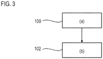
- the figure 3 shows a diagram of the attenuation method, or control method, of sound emissions to the environment of a test stand in which a turbomachine is tested.
- the test bench may correspond to that described in relation to the figures 1 and 2 .
- step (a) test 100 the equipment is excited in vibration due to the noise emissions produced by the turbomachine.
- the equipment can vibrate at its own frequency. It can also vibrate at one or more harmonics of its own frequency.
- the vibratory behavior of the equipment can include several additional frequencies, including its natural frequency and one or more harmonics.
- the active attenuation system transmits sound waves at the natural frequency of the equipment.
- the attenuation waves reach said equipment in phase opposition with respect to its vibration during step (a) test 100.
- the attenuation sound waves comprise a composite signal. , with several frequencies adding up. The different frequencies may have different amplitudes.
- the definition of the attenuation sound waves may be based on the measurements of the first microphone and the second microphone.
- the composite signal can adapt to reverberations.
- a learning phase or a calibration phase can be used to refine the sound attenuation provided by the active system.
Landscapes
- Engineering & Computer Science (AREA)
- Physics & Mathematics (AREA)
- Chemical & Material Sciences (AREA)
- Combustion & Propulsion (AREA)
- Mechanical Engineering (AREA)
- General Physics & Mathematics (AREA)
- General Engineering & Computer Science (AREA)
- Aviation & Aerospace Engineering (AREA)
- Multimedia (AREA)
- Acoustics & Sound (AREA)
- Manufacturing & Machinery (AREA)
- Transportation (AREA)
- Measurement Of Mechanical Vibrations Or Ultrasonic Waves (AREA)
- Testing Of Engines (AREA)
Priority Applications (1)
| Application Number | Priority Date | Filing Date | Title |
|---|---|---|---|
| PL17188927T PL3290897T3 (pl) | 2016-09-05 | 2017-09-01 | Stanowisko badawcze do maszyn wirowych z aktywną kontrolą hałasu |
Applications Claiming Priority (1)
| Application Number | Priority Date | Filing Date | Title |
|---|---|---|---|
| BE2016/5678A BE1024535B1 (fr) | 2016-09-05 | 2016-09-05 | Banc d'essai de turbomachine avec contrôle actif du bruit |
Publications (2)
| Publication Number | Publication Date |
|---|---|
| EP3290897A1 true EP3290897A1 (de) | 2018-03-07 |
| EP3290897B1 EP3290897B1 (de) | 2020-02-12 |
Family
ID=56990188
Family Applications (1)
| Application Number | Title | Priority Date | Filing Date |
|---|---|---|---|
| EP17188927.2A Active EP3290897B1 (de) | 2016-09-05 | 2017-09-01 | Prüfstand einer turbomaschine mit aktiver lärmkontrolle |
Country Status (9)
| Country | Link |
|---|---|
| US (1) | US10161267B2 (de) |
| EP (1) | EP3290897B1 (de) |
| CN (1) | CN107796630B (de) |
| BE (1) | BE1024535B1 (de) |
| BR (1) | BR102017018875A2 (de) |
| CA (1) | CA2976944A1 (de) |
| ES (1) | ES2777630T3 (de) |
| PL (1) | PL3290897T3 (de) |
| RU (1) | RU2017131037A (de) |
Cited By (5)
| Publication number | Priority date | Publication date | Assignee | Title |
|---|---|---|---|---|
| EP3588398A1 (de) | 2018-06-22 | 2020-01-01 | Safran Aero Boosters SA | Prüfstand mit wartungssystem, und wartungsverfahren eines solchen prüfstands |
| EP3599453A2 (de) | 2018-07-10 | 2020-01-29 | Safran Aero Boosters SA | Prüfstand für turbomaschine |
| WO2021009226A1 (fr) * | 2019-07-16 | 2021-01-21 | Safran Aero Boosters | Banc d'essai de turbomachines dépollué |
| CN112611556A (zh) * | 2020-12-02 | 2021-04-06 | 重庆市特种设备检测研究院 | 一种安全阀检测用测试台 |
| FR3119235A1 (fr) * | 2021-01-28 | 2022-07-29 | Safran Aircraft Engines | Cheminée d’admission de banc d’essais fermé pour turbomachine d’aéronef, banc d’essai et procédé d’utilisation |
Families Citing this family (6)
| Publication number | Priority date | Publication date | Assignee | Title |
|---|---|---|---|---|
| FR3078744B1 (fr) * | 2018-03-08 | 2020-11-20 | Safran Nacelles | Dispositif actif d’attenuation des emissions acoustiques pour un turboreacteur comportant des turbines controlees |
| CN108760329B (zh) * | 2018-05-21 | 2020-02-07 | 中国航发沈阳发动机研究所 | 一种低压涡轮噪声试验方法及其改进方法 |
| FR3084931B1 (fr) * | 2018-08-09 | 2020-08-07 | Safran Aircraft Engines | Pylone de support d'une turbomachine d'aeronef |
| CN112161786B (zh) * | 2020-09-18 | 2022-08-12 | 中国航发四川燃气涡轮研究院 | 旋转盘腔减涡器系统试验装置 |
| CN114893260B (zh) * | 2022-04-13 | 2024-03-15 | 东风汽车股份有限公司 | 一种简易消除增压器噪音的结构及其测试方法 |
| CN115112380A (zh) * | 2022-06-16 | 2022-09-27 | 中科南京未来能源系统研究院 | 一种燃烧室各部件声学特性的测量系统及测量方法 |
Citations (6)
| Publication number | Priority date | Publication date | Assignee | Title |
|---|---|---|---|---|
| WO1995019075A2 (en) | 1993-12-30 | 1995-07-13 | Bolt Beranek And Newman Inc. | Active muffler |
| US5650599A (en) * | 1993-04-13 | 1997-07-22 | Northrop Grumman Corporation | Noise cancellation method and apparatus |
| US5662136A (en) | 1995-09-11 | 1997-09-02 | Defense Research Technologies, Inc. | Acousto-fluidic driver for active control of turbofan engine noise |
| US20110138772A1 (en) * | 2009-12-16 | 2011-06-16 | Gley Zitouni | Turbine detuner for recovering kinetic energy from gas turbine engine exhaust gases |
| US20150134270A1 (en) * | 2013-11-12 | 2015-05-14 | Aero Systems Engineering, Inc. | Systems and methods for improved accuracy |
| EP3021102A1 (de) * | 2014-11-17 | 2016-05-18 | Techspace Aero S.A. | Prüfstand für axiale turbomaschine mit vertikaler windkraftanlage |
Family Cites Families (13)
| Publication number | Priority date | Publication date | Assignee | Title |
|---|---|---|---|---|
| US4520320A (en) * | 1981-09-10 | 1985-05-28 | The United States Of America As Represented By The Secretary Of Commerce | Synchronous phase marker and amplitude detector |
| EP0557071B1 (de) * | 1992-02-19 | 1999-05-12 | Hitachi, Ltd. | Aktives Lärmminderungsgerät für einen dreidimensionalen Raum |
| US5515444A (en) * | 1992-10-21 | 1996-05-07 | Virginia Polytechnic Institute And State University | Active control of aircraft engine inlet noise using compact sound sources and distributed error sensors |
| US6201872B1 (en) * | 1995-03-12 | 2001-03-13 | Hersh Acoustical Engineering, Inc. | Active control source cancellation and active control Helmholtz resonator absorption of axial fan rotor-stator interaction noise |
| US5828759A (en) * | 1995-11-30 | 1998-10-27 | Siemens Electric Limited | System and method for reducing engine noise |
| US6901147B1 (en) * | 1999-06-29 | 2005-05-31 | Kabushiki Kaisha Toshiba | Three-dimension active silencer |
| US7623993B2 (en) * | 2003-12-09 | 2009-11-24 | Iowa State University Research Foundation, Inc. | Method and system to perform energy-extraction based active noise control |
| EP1770685A1 (de) * | 2005-10-03 | 2007-04-04 | Maysound ApS | System zur Verminderung der hörbaren Wahrnehmung des Schallstörpegels eines Menschen. |
| US8459407B2 (en) * | 2008-10-01 | 2013-06-11 | General Electric Company | Sound attenuation systems and methods |
| US8256277B2 (en) * | 2009-06-11 | 2012-09-04 | United Technologies Corporation | Gas turbine engine debris monitoring arrangement |
| JPWO2011118218A1 (ja) * | 2010-03-26 | 2013-07-04 | パナソニック株式会社 | スピーカ装置、音制御装置、スピーカ装置が取り付けられた壁 |
| EP2667379B1 (de) * | 2012-05-21 | 2018-07-25 | Harman Becker Automotive Systems GmbH | Aktive Rauschunterdrückung |
| CN102914435A (zh) * | 2012-11-08 | 2013-02-06 | 中国汽车工程研究院股份有限公司 | 一种通过音频方式检测电控喷嘴响应时间的系统和方法 |
-
2016
- 2016-09-05 BE BE2016/5678A patent/BE1024535B1/fr not_active IP Right Cessation
-
2017
- 2017-08-22 CA CA2976944A patent/CA2976944A1/en not_active Abandoned
- 2017-08-23 US US15/683,881 patent/US10161267B2/en active Active
- 2017-09-01 PL PL17188927T patent/PL3290897T3/pl unknown
- 2017-09-01 BR BR102017018875-2A patent/BR102017018875A2/pt not_active IP Right Cessation
- 2017-09-01 EP EP17188927.2A patent/EP3290897B1/de active Active
- 2017-09-01 ES ES17188927T patent/ES2777630T3/es active Active
- 2017-09-04 RU RU2017131037A patent/RU2017131037A/ru not_active Application Discontinuation
- 2017-09-05 CN CN201710790748.XA patent/CN107796630B/zh active Active
Patent Citations (6)
| Publication number | Priority date | Publication date | Assignee | Title |
|---|---|---|---|---|
| US5650599A (en) * | 1993-04-13 | 1997-07-22 | Northrop Grumman Corporation | Noise cancellation method and apparatus |
| WO1995019075A2 (en) | 1993-12-30 | 1995-07-13 | Bolt Beranek And Newman Inc. | Active muffler |
| US5662136A (en) | 1995-09-11 | 1997-09-02 | Defense Research Technologies, Inc. | Acousto-fluidic driver for active control of turbofan engine noise |
| US20110138772A1 (en) * | 2009-12-16 | 2011-06-16 | Gley Zitouni | Turbine detuner for recovering kinetic energy from gas turbine engine exhaust gases |
| US20150134270A1 (en) * | 2013-11-12 | 2015-05-14 | Aero Systems Engineering, Inc. | Systems and methods for improved accuracy |
| EP3021102A1 (de) * | 2014-11-17 | 2016-05-18 | Techspace Aero S.A. | Prüfstand für axiale turbomaschine mit vertikaler windkraftanlage |
Cited By (9)
| Publication number | Priority date | Publication date | Assignee | Title |
|---|---|---|---|---|
| EP3588398A1 (de) | 2018-06-22 | 2020-01-01 | Safran Aero Boosters SA | Prüfstand mit wartungssystem, und wartungsverfahren eines solchen prüfstands |
| BE1026414B1 (fr) * | 2018-06-22 | 2020-01-30 | Safran Aero Boosters Sa | Banc d'essai avec système de maintenance |
| EP3599453A2 (de) | 2018-07-10 | 2020-01-29 | Safran Aero Boosters SA | Prüfstand für turbomaschine |
| EP3599453B1 (de) * | 2018-07-10 | 2023-12-27 | Safran Aero Boosters SA | Prüfstand für turbomaschine |
| WO2021009226A1 (fr) * | 2019-07-16 | 2021-01-21 | Safran Aero Boosters | Banc d'essai de turbomachines dépollué |
| BE1027431B1 (fr) * | 2019-07-16 | 2021-02-15 | Safran Aero Boosters Sa | Banc d'essai de turbomachines dépollué |
| CN112611556A (zh) * | 2020-12-02 | 2021-04-06 | 重庆市特种设备检测研究院 | 一种安全阀检测用测试台 |
| CN112611556B (zh) * | 2020-12-02 | 2023-01-13 | 重庆市特种设备检测研究院 | 一种安全阀检测用测试台 |
| FR3119235A1 (fr) * | 2021-01-28 | 2022-07-29 | Safran Aircraft Engines | Cheminée d’admission de banc d’essais fermé pour turbomachine d’aéronef, banc d’essai et procédé d’utilisation |
Also Published As
| Publication number | Publication date |
|---|---|
| CN107796630B (zh) | 2021-06-15 |
| BE1024535A1 (fr) | 2018-03-27 |
| CA2976944A1 (en) | 2018-03-05 |
| ES2777630T3 (es) | 2020-08-05 |
| US20180066545A1 (en) | 2018-03-08 |
| BR102017018875A2 (pt) | 2018-04-03 |
| US10161267B2 (en) | 2018-12-25 |
| PL3290897T3 (pl) | 2020-05-18 |
| RU2017131037A (ru) | 2019-03-04 |
| EP3290897B1 (de) | 2020-02-12 |
| CN107796630A (zh) | 2018-03-13 |
| BE1024535B1 (fr) | 2018-04-04 |
Similar Documents
| Publication | Publication Date | Title |
|---|---|---|
| EP3290897B1 (de) | Prüfstand einer turbomaschine mit aktiver lärmkontrolle | |
| CA2233253C (fr) | Dispositif d'attenuation acoustique active destine a etre dispose a l'interieur d'un conduit en particulier pour l'insonorisation de reseau de ventilation et/ou de climatisation | |
| EP2285682B1 (de) | Zwischen einer antriebseinheit und einem lufteinlass einer flugzeugtriebwerksgondel eingesetzter messgeräteträger | |
| CN103533488A (zh) | 亥姆霍兹共振器及其设计方法 | |
| FR3047270A1 (fr) | Echangeur thermique surfacique et traitement acoustique | |
| CN107636272B (zh) | 用于压力振动阻尼的声学衰减器、使用该衰减器的声学衰减系统和压力振动阻尼的方法 | |
| FR2618561A1 (fr) | Procede et dispositif pour determiner le nombre de mach sans intrusion | |
| CN106932481B (zh) | 一种消音器消音特性测试系统 | |
| JP6579924B2 (ja) | 煙突騒音低減システム及び煙突騒音低減システムの設定方法 | |
| EP2375029B1 (de) | Kühlkreislauf mit einer Vorrichtung zum Isolieren | |
| FR2589195A1 (fr) | Cheminee insonorisee pour gaz chauds ejectes d'un tube d'echappement | |
| FR3069850B1 (fr) | Systeme actif generant des interferences acoustiques destructives pour moteur d'aeronef a plusieurs corps de soufflante | |
| JP2017089567A (ja) | 煙突騒音低減装置 | |
| RU2634979C1 (ru) | Заглушенная камера для акустических и газодинамических измерений шумов элементов конструкции авиационных ГТД | |
| Selamet et al. | Whistles with a generic sidebranch: production and suppression | |
| Du et al. | Experimental study on noise reduction effect of a muffler inserted in liquid transporting pipeline | |
| FR3023645A1 (fr) | Dispositif et methode d'attenuation du son | |
| Witte et al. | Principal experimental study of the acoustic behavior of pumps | |
| Kuai et al. | An Impedance Eduction Technique for the Multimodal Cylindrical Duct With Termination Reflecting | |
| Bonelli et al. | The turbulence between geomechanics and vibroacoustics: what is common point? | |
| EP3760924A1 (de) | Schalldämmvorrichtung für ein rauchgasabzugsrohr einer raucherzeugenden vorrichtung | |
| FR2958329A1 (fr) | Procede de conception de la structure d'un circuit de refroidissement | |
| Büssow | Development of a Duct Silencer for Heavy Industrial Compressor Systems | |
| SU937741A1 (ru) | Стендовый глушитель | |
| Brand et al. | Surface radiated noise of exhaust systems–structural transmission loss test rig, part 1 |
Legal Events
| Date | Code | Title | Description |
|---|---|---|---|
| PUAI | Public reference made under article 153(3) epc to a published international application that has entered the european phase |
Free format text: ORIGINAL CODE: 0009012 |
|
| STAA | Information on the status of an ep patent application or granted ep patent |
Free format text: STATUS: THE APPLICATION HAS BEEN PUBLISHED |
|
| AK | Designated contracting states |
Kind code of ref document: A1 Designated state(s): AL AT BE BG CH CY CZ DE DK EE ES FI FR GB GR HR HU IE IS IT LI LT LU LV MC MK MT NL NO PL PT RO RS SE SI SK SM TR |
|
| AX | Request for extension of the european patent |
Extension state: BA ME |
|
| STAA | Information on the status of an ep patent application or granted ep patent |
Free format text: STATUS: REQUEST FOR EXAMINATION WAS MADE |
|
| 17P | Request for examination filed |
Effective date: 20180827 |
|
| RBV | Designated contracting states (corrected) |
Designated state(s): AL AT BE BG CH CY CZ DE DK EE ES FI FR GB GR HR HU IE IS IT LI LT LU LV MC MK MT NL NO PL PT RO RS SE SI SK SM TR |
|
| REG | Reference to a national code |
Ref country code: DE Ref legal event code: R079 Ref document number: 602017011543 Country of ref document: DE Free format text: PREVIOUS MAIN CLASS: G01M0015140000 Ipc: G01M0015020000 |
|
| RIC1 | Information provided on ipc code assigned before grant |
Ipc: F02K 1/82 20060101ALI20190716BHEP Ipc: F01D 21/00 20060101ALI20190716BHEP Ipc: G01M 15/14 20060101ALI20190716BHEP Ipc: F02C 7/045 20060101ALI20190716BHEP Ipc: B64F 5/60 20170101ALI20190716BHEP Ipc: F02K 1/44 20060101ALI20190716BHEP Ipc: G01M 15/02 20060101AFI20190716BHEP Ipc: G10K 11/178 20060101ALI20190716BHEP |
|
| GRAP | Despatch of communication of intention to grant a patent |
Free format text: ORIGINAL CODE: EPIDOSNIGR1 |
|
| STAA | Information on the status of an ep patent application or granted ep patent |
Free format text: STATUS: GRANT OF PATENT IS INTENDED |
|
| INTG | Intention to grant announced |
Effective date: 20190830 |
|
| GRAS | Grant fee paid |
Free format text: ORIGINAL CODE: EPIDOSNIGR3 |
|
| GRAA | (expected) grant |
Free format text: ORIGINAL CODE: 0009210 |
|
| STAA | Information on the status of an ep patent application or granted ep patent |
Free format text: STATUS: THE PATENT HAS BEEN GRANTED |
|
| AK | Designated contracting states |
Kind code of ref document: B1 Designated state(s): AL AT BE BG CH CY CZ DE DK EE ES FI FR GB GR HR HU IE IS IT LI LT LU LV MC MK MT NL NO PL PT RO RS SE SI SK SM TR |
|
| REG | Reference to a national code |
Ref country code: GB Ref legal event code: FG4D Free format text: NOT ENGLISH |
|
| REG | Reference to a national code |
Ref country code: CH Ref legal event code: EP |
|
| REG | Reference to a national code |
Ref country code: AT Ref legal event code: REF Ref document number: 1232766 Country of ref document: AT Kind code of ref document: T Effective date: 20200215 |
|
| REG | Reference to a national code |
Ref country code: IE Ref legal event code: FG4D Free format text: LANGUAGE OF EP DOCUMENT: FRENCH |
|
| REG | Reference to a national code |
Ref country code: DE Ref legal event code: R096 Ref document number: 602017011543 Country of ref document: DE |
|
| REG | Reference to a national code |
Ref country code: SE Ref legal event code: TRGR |
|
| REG | Reference to a national code |
Ref country code: NL Ref legal event code: FP |
|
| PG25 | Lapsed in a contracting state [announced via postgrant information from national office to epo] |
Ref country code: RS Free format text: LAPSE BECAUSE OF FAILURE TO SUBMIT A TRANSLATION OF THE DESCRIPTION OR TO PAY THE FEE WITHIN THE PRESCRIBED TIME-LIMIT Effective date: 20200212 Ref country code: FI Free format text: LAPSE BECAUSE OF FAILURE TO SUBMIT A TRANSLATION OF THE DESCRIPTION OR TO PAY THE FEE WITHIN THE PRESCRIBED TIME-LIMIT Effective date: 20200212 Ref country code: NO Free format text: LAPSE BECAUSE OF FAILURE TO SUBMIT A TRANSLATION OF THE DESCRIPTION OR TO PAY THE FEE WITHIN THE PRESCRIBED TIME-LIMIT Effective date: 20200512 |
|
| REG | Reference to a national code |
Ref country code: ES Ref legal event code: FG2A Ref document number: 2777630 Country of ref document: ES Kind code of ref document: T3 Effective date: 20200805 |
|
| REG | Reference to a national code |
Ref country code: LT Ref legal event code: MG4D |
|
| PG25 | Lapsed in a contracting state [announced via postgrant information from national office to epo] |
Ref country code: HR Free format text: LAPSE BECAUSE OF FAILURE TO SUBMIT A TRANSLATION OF THE DESCRIPTION OR TO PAY THE FEE WITHIN THE PRESCRIBED TIME-LIMIT Effective date: 20200212 Ref country code: GR Free format text: LAPSE BECAUSE OF FAILURE TO SUBMIT A TRANSLATION OF THE DESCRIPTION OR TO PAY THE FEE WITHIN THE PRESCRIBED TIME-LIMIT Effective date: 20200513 Ref country code: LV Free format text: LAPSE BECAUSE OF FAILURE TO SUBMIT A TRANSLATION OF THE DESCRIPTION OR TO PAY THE FEE WITHIN THE PRESCRIBED TIME-LIMIT Effective date: 20200212 Ref country code: IS Free format text: LAPSE BECAUSE OF FAILURE TO SUBMIT A TRANSLATION OF THE DESCRIPTION OR TO PAY THE FEE WITHIN THE PRESCRIBED TIME-LIMIT Effective date: 20200612 Ref country code: BG Free format text: LAPSE BECAUSE OF FAILURE TO SUBMIT A TRANSLATION OF THE DESCRIPTION OR TO PAY THE FEE WITHIN THE PRESCRIBED TIME-LIMIT Effective date: 20200512 |
|
| PG25 | Lapsed in a contracting state [announced via postgrant information from national office to epo] |
Ref country code: CZ Free format text: LAPSE BECAUSE OF FAILURE TO SUBMIT A TRANSLATION OF THE DESCRIPTION OR TO PAY THE FEE WITHIN THE PRESCRIBED TIME-LIMIT Effective date: 20200212 Ref country code: RO Free format text: LAPSE BECAUSE OF FAILURE TO SUBMIT A TRANSLATION OF THE DESCRIPTION OR TO PAY THE FEE WITHIN THE PRESCRIBED TIME-LIMIT Effective date: 20200212 Ref country code: PT Free format text: LAPSE BECAUSE OF FAILURE TO SUBMIT A TRANSLATION OF THE DESCRIPTION OR TO PAY THE FEE WITHIN THE PRESCRIBED TIME-LIMIT Effective date: 20200705 Ref country code: EE Free format text: LAPSE BECAUSE OF FAILURE TO SUBMIT A TRANSLATION OF THE DESCRIPTION OR TO PAY THE FEE WITHIN THE PRESCRIBED TIME-LIMIT Effective date: 20200212 Ref country code: SM Free format text: LAPSE BECAUSE OF FAILURE TO SUBMIT A TRANSLATION OF THE DESCRIPTION OR TO PAY THE FEE WITHIN THE PRESCRIBED TIME-LIMIT Effective date: 20200212 Ref country code: DK Free format text: LAPSE BECAUSE OF FAILURE TO SUBMIT A TRANSLATION OF THE DESCRIPTION OR TO PAY THE FEE WITHIN THE PRESCRIBED TIME-LIMIT Effective date: 20200212 Ref country code: LT Free format text: LAPSE BECAUSE OF FAILURE TO SUBMIT A TRANSLATION OF THE DESCRIPTION OR TO PAY THE FEE WITHIN THE PRESCRIBED TIME-LIMIT Effective date: 20200212 Ref country code: SK Free format text: LAPSE BECAUSE OF FAILURE TO SUBMIT A TRANSLATION OF THE DESCRIPTION OR TO PAY THE FEE WITHIN THE PRESCRIBED TIME-LIMIT Effective date: 20200212 |
|
| REG | Reference to a national code |
Ref country code: DE Ref legal event code: R097 Ref document number: 602017011543 Country of ref document: DE |
|
| REG | Reference to a national code |
Ref country code: AT Ref legal event code: MK05 Ref document number: 1232766 Country of ref document: AT Kind code of ref document: T Effective date: 20200212 |
|
| PLBE | No opposition filed within time limit |
Free format text: ORIGINAL CODE: 0009261 |
|
| STAA | Information on the status of an ep patent application or granted ep patent |
Free format text: STATUS: NO OPPOSITION FILED WITHIN TIME LIMIT |
|
| 26N | No opposition filed |
Effective date: 20201113 |
|
| PG25 | Lapsed in a contracting state [announced via postgrant information from national office to epo] |
Ref country code: AT Free format text: LAPSE BECAUSE OF FAILURE TO SUBMIT A TRANSLATION OF THE DESCRIPTION OR TO PAY THE FEE WITHIN THE PRESCRIBED TIME-LIMIT Effective date: 20200212 |
|
| PG25 | Lapsed in a contracting state [announced via postgrant information from national office to epo] |
Ref country code: SI Free format text: LAPSE BECAUSE OF FAILURE TO SUBMIT A TRANSLATION OF THE DESCRIPTION OR TO PAY THE FEE WITHIN THE PRESCRIBED TIME-LIMIT Effective date: 20200212 |
|
| REG | Reference to a national code |
Ref country code: CH Ref legal event code: PL |
|
| PG25 | Lapsed in a contracting state [announced via postgrant information from national office to epo] |
Ref country code: LU Free format text: LAPSE BECAUSE OF NON-PAYMENT OF DUE FEES Effective date: 20200901 |
|
| PG25 | Lapsed in a contracting state [announced via postgrant information from national office to epo] |
Ref country code: CH Free format text: LAPSE BECAUSE OF NON-PAYMENT OF DUE FEES Effective date: 20200930 Ref country code: LI Free format text: LAPSE BECAUSE OF NON-PAYMENT OF DUE FEES Effective date: 20200930 Ref country code: IE Free format text: LAPSE BECAUSE OF NON-PAYMENT OF DUE FEES Effective date: 20200901 |
|
| PG25 | Lapsed in a contracting state [announced via postgrant information from national office to epo] |
Ref country code: TR Free format text: LAPSE BECAUSE OF FAILURE TO SUBMIT A TRANSLATION OF THE DESCRIPTION OR TO PAY THE FEE WITHIN THE PRESCRIBED TIME-LIMIT Effective date: 20200212 Ref country code: MT Free format text: LAPSE BECAUSE OF FAILURE TO SUBMIT A TRANSLATION OF THE DESCRIPTION OR TO PAY THE FEE WITHIN THE PRESCRIBED TIME-LIMIT Effective date: 20200212 Ref country code: CY Free format text: LAPSE BECAUSE OF FAILURE TO SUBMIT A TRANSLATION OF THE DESCRIPTION OR TO PAY THE FEE WITHIN THE PRESCRIBED TIME-LIMIT Effective date: 20200212 |
|
| PG25 | Lapsed in a contracting state [announced via postgrant information from national office to epo] |
Ref country code: MK Free format text: LAPSE BECAUSE OF FAILURE TO SUBMIT A TRANSLATION OF THE DESCRIPTION OR TO PAY THE FEE WITHIN THE PRESCRIBED TIME-LIMIT Effective date: 20200212 Ref country code: MC Free format text: LAPSE BECAUSE OF FAILURE TO SUBMIT A TRANSLATION OF THE DESCRIPTION OR TO PAY THE FEE WITHIN THE PRESCRIBED TIME-LIMIT Effective date: 20200212 Ref country code: AL Free format text: LAPSE BECAUSE OF FAILURE TO SUBMIT A TRANSLATION OF THE DESCRIPTION OR TO PAY THE FEE WITHIN THE PRESCRIBED TIME-LIMIT Effective date: 20200212 |
|
| PGFP | Annual fee paid to national office [announced via postgrant information from national office to epo] |
Ref country code: DE Payment date: 20250919 Year of fee payment: 9 |
|
| PGFP | Annual fee paid to national office [announced via postgrant information from national office to epo] |
Ref country code: PL Payment date: 20250822 Year of fee payment: 9 Ref country code: NL Payment date: 20250922 Year of fee payment: 9 |
|
| PGFP | Annual fee paid to national office [announced via postgrant information from national office to epo] |
Ref country code: GB Payment date: 20250923 Year of fee payment: 9 Ref country code: BE Payment date: 20250919 Year of fee payment: 9 |
|
| PGFP | Annual fee paid to national office [announced via postgrant information from national office to epo] |
Ref country code: FR Payment date: 20250924 Year of fee payment: 9 |
|
| PGFP | Annual fee paid to national office [announced via postgrant information from national office to epo] |
Ref country code: SE Payment date: 20250922 Year of fee payment: 9 |
|
| PGFP | Annual fee paid to national office [announced via postgrant information from national office to epo] |
Ref country code: IT Payment date: 20250930 Year of fee payment: 9 |
|
| PGFP | Annual fee paid to national office [announced via postgrant information from national office to epo] |
Ref country code: ES Payment date: 20251020 Year of fee payment: 9 |