EP3290900A1 - Condenseur de substance chimique - Google Patents
Condenseur de substance chimique Download PDFInfo
- Publication number
- EP3290900A1 EP3290900A1 EP16786143.4A EP16786143A EP3290900A1 EP 3290900 A1 EP3290900 A1 EP 3290900A1 EP 16786143 A EP16786143 A EP 16786143A EP 3290900 A1 EP3290900 A1 EP 3290900A1
- Authority
- EP
- European Patent Office
- Prior art keywords
- chemical substance
- adsorption
- adsorption parts
- tubular body
- substance concentrator
- Prior art date
- Legal status (The legal status is an assumption and is not a legal conclusion. Google has not performed a legal analysis and makes no representation as to the accuracy of the status listed.)
- Withdrawn
Links
- 239000000126 substance Substances 0.000 title claims abstract description 165
- 238000001179 sorption measurement Methods 0.000 claims abstract description 181
- 238000010438 heat treatment Methods 0.000 claims description 50
- 239000000835 fiber Substances 0.000 claims description 48
- 238000003795 desorption Methods 0.000 claims description 19
- 238000004220 aggregation Methods 0.000 claims description 5
- 230000002776 aggregation Effects 0.000 claims description 5
- 229910044991 metal oxide Inorganic materials 0.000 claims description 4
- 150000004706 metal oxides Chemical class 0.000 claims description 4
- 230000001678 irradiating effect Effects 0.000 claims description 2
- 239000000463 material Substances 0.000 description 27
- 239000002121 nanofiber Substances 0.000 description 13
- 239000012855 volatile organic compound Substances 0.000 description 10
- 239000013078 crystal Substances 0.000 description 7
- 238000001514 detection method Methods 0.000 description 7
- 239000007789 gas Substances 0.000 description 5
- 239000000758 substrate Substances 0.000 description 5
- 238000000034 method Methods 0.000 description 4
- 239000002245 particle Substances 0.000 description 4
- VYPSYNLAJGMNEJ-UHFFFAOYSA-N silicon dioxide Inorganic materials O=[Si]=O VYPSYNLAJGMNEJ-UHFFFAOYSA-N 0.000 description 4
- 238000004544 sputter deposition Methods 0.000 description 4
- MWUXSHHQAYIFBG-UHFFFAOYSA-N Nitric oxide Chemical compound O=[N] MWUXSHHQAYIFBG-UHFFFAOYSA-N 0.000 description 3
- QGZKDVFQNNGYKY-UHFFFAOYSA-N Ammonia Chemical compound N QGZKDVFQNNGYKY-UHFFFAOYSA-N 0.000 description 2
- QPLDLSVMHZLSFG-UHFFFAOYSA-N Copper oxide Chemical compound [Cu]=O QPLDLSVMHZLSFG-UHFFFAOYSA-N 0.000 description 2
- PXHVJJICTQNCMI-UHFFFAOYSA-N Nickel Chemical compound [Ni] PXHVJJICTQNCMI-UHFFFAOYSA-N 0.000 description 2
- KDLHZDBZIXYQEI-UHFFFAOYSA-N Palladium Chemical compound [Pd] KDLHZDBZIXYQEI-UHFFFAOYSA-N 0.000 description 2
- GWEVSGVZZGPLCZ-UHFFFAOYSA-N Titan oxide Chemical compound O=[Ti]=O GWEVSGVZZGPLCZ-UHFFFAOYSA-N 0.000 description 2
- 239000003463 adsorbent Substances 0.000 description 2
- 230000000052 comparative effect Effects 0.000 description 2
- PMHQVHHXPFUNSP-UHFFFAOYSA-M copper(1+);methylsulfanylmethane;bromide Chemical compound Br[Cu].CSC PMHQVHHXPFUNSP-UHFFFAOYSA-M 0.000 description 2
- 239000004205 dimethyl polysiloxane Substances 0.000 description 2
- 235000013870 dimethyl polysiloxane Nutrition 0.000 description 2
- 239000006185 dispersion Substances 0.000 description 2
- 239000012530 fluid Substances 0.000 description 2
- 239000011521 glass Substances 0.000 description 2
- 239000012212 insulator Substances 0.000 description 2
- 239000007791 liquid phase Substances 0.000 description 2
- 229910052751 metal Inorganic materials 0.000 description 2
- 239000002184 metal Substances 0.000 description 2
- 238000005240 physical vapour deposition Methods 0.000 description 2
- 229920000435 poly(dimethylsiloxane) Polymers 0.000 description 2
- XOLBLPGZBRYERU-UHFFFAOYSA-N tin dioxide Chemical compound O=[Sn]=O XOLBLPGZBRYERU-UHFFFAOYSA-N 0.000 description 2
- 239000012808 vapor phase Substances 0.000 description 2
- UGFAIRIUMAVXCW-UHFFFAOYSA-N Carbon monoxide Chemical compound [O+]#[C-] UGFAIRIUMAVXCW-UHFFFAOYSA-N 0.000 description 1
- ZAMOUSCENKQFHK-UHFFFAOYSA-N Chlorine atom Chemical compound [Cl] ZAMOUSCENKQFHK-UHFFFAOYSA-N 0.000 description 1
- UFHFLCQGNIYNRP-UHFFFAOYSA-N Hydrogen Chemical compound [H][H] UFHFLCQGNIYNRP-UHFFFAOYSA-N 0.000 description 1
- ZOKXTWBITQBERF-UHFFFAOYSA-N Molybdenum Chemical compound [Mo] ZOKXTWBITQBERF-UHFFFAOYSA-N 0.000 description 1
- 229910020294 Pb(Zr,Ti)O3 Inorganic materials 0.000 description 1
- 239000002202 Polyethylene glycol Substances 0.000 description 1
- XUIMIQQOPSSXEZ-UHFFFAOYSA-N Silicon Chemical compound [Si] XUIMIQQOPSSXEZ-UHFFFAOYSA-N 0.000 description 1
- 229910021536 Zeolite Inorganic materials 0.000 description 1
- 230000001154 acute effect Effects 0.000 description 1
- 229910021529 ammonia Inorganic materials 0.000 description 1
- QVGXLLKOCUKJST-UHFFFAOYSA-N atomic oxygen Chemical compound [O] QVGXLLKOCUKJST-UHFFFAOYSA-N 0.000 description 1
- 229910002091 carbon monoxide Inorganic materials 0.000 description 1
- 239000002134 carbon nanofiber Substances 0.000 description 1
- 239000003054 catalyst Substances 0.000 description 1
- 239000000919 ceramic Substances 0.000 description 1
- 239000000460 chlorine Substances 0.000 description 1
- 229910052801 chlorine Inorganic materials 0.000 description 1
- VNNRSPGTAMTISX-UHFFFAOYSA-N chromium nickel Chemical compound [Cr].[Ni] VNNRSPGTAMTISX-UHFFFAOYSA-N 0.000 description 1
- 229910052681 coesite Inorganic materials 0.000 description 1
- 238000001816 cooling Methods 0.000 description 1
- 229910052906 cristobalite Inorganic materials 0.000 description 1
- 238000010586 diagram Methods 0.000 description 1
- HNPSIPDUKPIQMN-UHFFFAOYSA-N dioxosilane;oxo(oxoalumanyloxy)alumane Chemical compound O=[Si]=O.O=[Al]O[Al]=O HNPSIPDUKPIQMN-UHFFFAOYSA-N 0.000 description 1
- 238000007599 discharging Methods 0.000 description 1
- 230000003628 erosive effect Effects 0.000 description 1
- 229910052736 halogen Inorganic materials 0.000 description 1
- 150000002367 halogens Chemical class 0.000 description 1
- 239000001257 hydrogen Substances 0.000 description 1
- 229910052739 hydrogen Inorganic materials 0.000 description 1
- PJXISJQVUVHSOJ-UHFFFAOYSA-N indium(III) oxide Inorganic materials [O-2].[O-2].[O-2].[In+3].[In+3] PJXISJQVUVHSOJ-UHFFFAOYSA-N 0.000 description 1
- 239000011810 insulating material Substances 0.000 description 1
- HFGPZNIAWCZYJU-UHFFFAOYSA-N lead zirconate titanate Chemical compound [O-2].[O-2].[O-2].[O-2].[O-2].[Ti+4].[Zr+4].[Pb+2] HFGPZNIAWCZYJU-UHFFFAOYSA-N 0.000 description 1
- 229910052451 lead zirconate titanate Inorganic materials 0.000 description 1
- VNWKTOKETHGBQD-UHFFFAOYSA-N methane Chemical compound C VNWKTOKETHGBQD-UHFFFAOYSA-N 0.000 description 1
- 238000012986 modification Methods 0.000 description 1
- 230000004048 modification Effects 0.000 description 1
- 229910052750 molybdenum Inorganic materials 0.000 description 1
- 239000011733 molybdenum Substances 0.000 description 1
- 239000002070 nanowire Substances 0.000 description 1
- 229910001120 nichrome Inorganic materials 0.000 description 1
- 229910052759 nickel Inorganic materials 0.000 description 1
- GNRSAWUEBMWBQH-UHFFFAOYSA-N nickel(II) oxide Inorganic materials [Ni]=O GNRSAWUEBMWBQH-UHFFFAOYSA-N 0.000 description 1
- CXQXSVUQTKDNFP-UHFFFAOYSA-N octamethyltrisiloxane Chemical compound C[Si](C)(C)O[Si](C)(C)O[Si](C)(C)C CXQXSVUQTKDNFP-UHFFFAOYSA-N 0.000 description 1
- 239000001301 oxygen Substances 0.000 description 1
- 229910052760 oxygen Inorganic materials 0.000 description 1
- 229910052763 palladium Inorganic materials 0.000 description 1
- 238000004987 plasma desorption mass spectroscopy Methods 0.000 description 1
- 229920000767 polyaniline Polymers 0.000 description 1
- 229920001223 polyethylene glycol Polymers 0.000 description 1
- 239000010453 quartz Substances 0.000 description 1
- 238000005096 rolling process Methods 0.000 description 1
- 102220218873 rs1060503403 Human genes 0.000 description 1
- 229910052594 sapphire Inorganic materials 0.000 description 1
- 239000010980 sapphire Substances 0.000 description 1
- 229910052710 silicon Inorganic materials 0.000 description 1
- 239000010703 silicon Substances 0.000 description 1
- 239000000377 silicon dioxide Substances 0.000 description 1
- 229910052814 silicon oxide Inorganic materials 0.000 description 1
- 229910052709 silver Inorganic materials 0.000 description 1
- 239000004332 silver Substances 0.000 description 1
- 239000007787 solid Substances 0.000 description 1
- 230000003068 static effect Effects 0.000 description 1
- 229910052682 stishovite Inorganic materials 0.000 description 1
- 239000010409 thin film Substances 0.000 description 1
- 229910052905 tridymite Inorganic materials 0.000 description 1
- XLYOFNOQVPJJNP-UHFFFAOYSA-N water Substances O XLYOFNOQVPJJNP-UHFFFAOYSA-N 0.000 description 1
- 239000010457 zeolite Substances 0.000 description 1
- XLOMVQKBTHCTTD-UHFFFAOYSA-N zinc oxide Inorganic materials [Zn]=O XLOMVQKBTHCTTD-UHFFFAOYSA-N 0.000 description 1
Images



Classifications
-
- G—PHYSICS
- G01—MEASURING; TESTING
- G01N—INVESTIGATING OR ANALYSING MATERIALS BY DETERMINING THEIR CHEMICAL OR PHYSICAL PROPERTIES
- G01N1/00—Sampling; Preparing specimens for investigation
- G01N1/28—Preparing specimens for investigation including physical details of (bio-)chemical methods covered elsewhere, e.g. G01N33/50, C12Q
- G01N1/40—Concentrating samples
- G01N1/405—Concentrating samples by adsorption or absorption
-
- B—PERFORMING OPERATIONS; TRANSPORTING
- B01—PHYSICAL OR CHEMICAL PROCESSES OR APPARATUS IN GENERAL
- B01D—SEPARATION
- B01D53/00—Separation of gases or vapours; Recovering vapours of volatile solvents from gases; Chemical or biological purification of waste gases, e.g. engine exhaust gases, smoke, fumes, flue gases, aerosols
- B01D53/02—Separation of gases or vapours; Recovering vapours of volatile solvents from gases; Chemical or biological purification of waste gases, e.g. engine exhaust gases, smoke, fumes, flue gases, aerosols by adsorption, e.g. preparative gas chromatography
- B01D53/04—Separation of gases or vapours; Recovering vapours of volatile solvents from gases; Chemical or biological purification of waste gases, e.g. engine exhaust gases, smoke, fumes, flue gases, aerosols by adsorption, e.g. preparative gas chromatography with stationary adsorbents
- B01D53/0407—Constructional details of adsorbing systems
-
- B—PERFORMING OPERATIONS; TRANSPORTING
- B01—PHYSICAL OR CHEMICAL PROCESSES OR APPARATUS IN GENERAL
- B01D—SEPARATION
- B01D53/00—Separation of gases or vapours; Recovering vapours of volatile solvents from gases; Chemical or biological purification of waste gases, e.g. engine exhaust gases, smoke, fumes, flue gases, aerosols
- B01D53/02—Separation of gases or vapours; Recovering vapours of volatile solvents from gases; Chemical or biological purification of waste gases, e.g. engine exhaust gases, smoke, fumes, flue gases, aerosols by adsorption, e.g. preparative gas chromatography
- B01D53/04—Separation of gases or vapours; Recovering vapours of volatile solvents from gases; Chemical or biological purification of waste gases, e.g. engine exhaust gases, smoke, fumes, flue gases, aerosols by adsorption, e.g. preparative gas chromatography with stationary adsorbents
-
- B—PERFORMING OPERATIONS; TRANSPORTING
- B01—PHYSICAL OR CHEMICAL PROCESSES OR APPARATUS IN GENERAL
- B01D—SEPARATION
- B01D53/00—Separation of gases or vapours; Recovering vapours of volatile solvents from gases; Chemical or biological purification of waste gases, e.g. engine exhaust gases, smoke, fumes, flue gases, aerosols
- B01D53/02—Separation of gases or vapours; Recovering vapours of volatile solvents from gases; Chemical or biological purification of waste gases, e.g. engine exhaust gases, smoke, fumes, flue gases, aerosols by adsorption, e.g. preparative gas chromatography
- B01D53/04—Separation of gases or vapours; Recovering vapours of volatile solvents from gases; Chemical or biological purification of waste gases, e.g. engine exhaust gases, smoke, fumes, flue gases, aerosols by adsorption, e.g. preparative gas chromatography with stationary adsorbents
- B01D53/0407—Constructional details of adsorbing systems
- B01D53/0438—Cooling or heating systems
-
- B—PERFORMING OPERATIONS; TRANSPORTING
- B01—PHYSICAL OR CHEMICAL PROCESSES OR APPARATUS IN GENERAL
- B01J—CHEMICAL OR PHYSICAL PROCESSES, e.g. CATALYSIS OR COLLOID CHEMISTRY; THEIR RELEVANT APPARATUS
- B01J20/00—Solid sorbent compositions or filter aid compositions; Sorbents for chromatography; Processes for preparing, regenerating or reactivating thereof
- B01J20/02—Solid sorbent compositions or filter aid compositions; Sorbents for chromatography; Processes for preparing, regenerating or reactivating thereof comprising inorganic material
- B01J20/06—Solid sorbent compositions or filter aid compositions; Sorbents for chromatography; Processes for preparing, regenerating or reactivating thereof comprising inorganic material comprising oxides or hydroxides of metals not provided for in group B01J20/04
-
- B—PERFORMING OPERATIONS; TRANSPORTING
- B01—PHYSICAL OR CHEMICAL PROCESSES OR APPARATUS IN GENERAL
- B01J—CHEMICAL OR PHYSICAL PROCESSES, e.g. CATALYSIS OR COLLOID CHEMISTRY; THEIR RELEVANT APPARATUS
- B01J20/00—Solid sorbent compositions or filter aid compositions; Sorbents for chromatography; Processes for preparing, regenerating or reactivating thereof
- B01J20/02—Solid sorbent compositions or filter aid compositions; Sorbents for chromatography; Processes for preparing, regenerating or reactivating thereof comprising inorganic material
- B01J20/20—Solid sorbent compositions or filter aid compositions; Sorbents for chromatography; Processes for preparing, regenerating or reactivating thereof comprising inorganic material comprising free carbon; comprising carbon obtained by carbonising processes
- B01J20/205—Carbon nanostructures, e.g. nanotubes, nanohorns, nanocones, nanoballs
-
- B—PERFORMING OPERATIONS; TRANSPORTING
- B01—PHYSICAL OR CHEMICAL PROCESSES OR APPARATUS IN GENERAL
- B01J—CHEMICAL OR PHYSICAL PROCESSES, e.g. CATALYSIS OR COLLOID CHEMISTRY; THEIR RELEVANT APPARATUS
- B01J20/00—Solid sorbent compositions or filter aid compositions; Sorbents for chromatography; Processes for preparing, regenerating or reactivating thereof
- B01J20/28—Solid sorbent compositions or filter aid compositions; Sorbents for chromatography; Processes for preparing, regenerating or reactivating thereof characterised by their form or physical properties
- B01J20/28014—Solid sorbent compositions or filter aid compositions; Sorbents for chromatography; Processes for preparing, regenerating or reactivating thereof characterised by their form or physical properties characterised by their form
- B01J20/28023—Fibres or filaments
-
- G—PHYSICS
- G01—MEASURING; TESTING
- G01N—INVESTIGATING OR ANALYSING MATERIALS BY DETERMINING THEIR CHEMICAL OR PHYSICAL PROPERTIES
- G01N1/00—Sampling; Preparing specimens for investigation
- G01N1/02—Devices for withdrawing samples
- G01N1/22—Devices for withdrawing samples in the gaseous state
-
- G—PHYSICS
- G01—MEASURING; TESTING
- G01N—INVESTIGATING OR ANALYSING MATERIALS BY DETERMINING THEIR CHEMICAL OR PHYSICAL PROPERTIES
- G01N1/00—Sampling; Preparing specimens for investigation
- G01N1/02—Devices for withdrawing samples
- G01N1/22—Devices for withdrawing samples in the gaseous state
- G01N1/2202—Devices for withdrawing samples in the gaseous state involving separation of sample components during sampling
- G01N1/2214—Devices for withdrawing samples in the gaseous state involving separation of sample components during sampling by sorption
-
- G—PHYSICS
- G01—MEASURING; TESTING
- G01N—INVESTIGATING OR ANALYSING MATERIALS BY DETERMINING THEIR CHEMICAL OR PHYSICAL PROPERTIES
- G01N1/00—Sampling; Preparing specimens for investigation
- G01N1/02—Devices for withdrawing samples
- G01N1/22—Devices for withdrawing samples in the gaseous state
- G01N1/2247—Sampling from a flowing stream of gas
-
- G—PHYSICS
- G01—MEASURING; TESTING
- G01N—INVESTIGATING OR ANALYSING MATERIALS BY DETERMINING THEIR CHEMICAL OR PHYSICAL PROPERTIES
- G01N27/00—Investigating or analysing materials by the use of electric, electrochemical, or magnetic means
- G01N27/02—Investigating or analysing materials by the use of electric, electrochemical, or magnetic means by investigating impedance
- G01N27/04—Investigating or analysing materials by the use of electric, electrochemical, or magnetic means by investigating impedance by investigating resistance
- G01N27/12—Investigating or analysing materials by the use of electric, electrochemical, or magnetic means by investigating impedance by investigating resistance of a solid body in dependence upon absorption of a fluid; of a solid body in dependence upon reaction with a fluid, for detecting components in the fluid
- G01N27/125—Composition of the body, e.g. the composition of its sensitive layer
-
- B—PERFORMING OPERATIONS; TRANSPORTING
- B01—PHYSICAL OR CHEMICAL PROCESSES OR APPARATUS IN GENERAL
- B01D—SEPARATION
- B01D2253/00—Adsorbents used in seperation treatment of gases and vapours
- B01D2253/10—Inorganic adsorbents
- B01D2253/102—Carbon
-
- B—PERFORMING OPERATIONS; TRANSPORTING
- B01—PHYSICAL OR CHEMICAL PROCESSES OR APPARATUS IN GENERAL
- B01D—SEPARATION
- B01D2253/00—Adsorbents used in seperation treatment of gases and vapours
- B01D2253/10—Inorganic adsorbents
- B01D2253/106—Silica or silicates
- B01D2253/108—Zeolites
-
- B—PERFORMING OPERATIONS; TRANSPORTING
- B01—PHYSICAL OR CHEMICAL PROCESSES OR APPARATUS IN GENERAL
- B01D—SEPARATION
- B01D2253/00—Adsorbents used in seperation treatment of gases and vapours
- B01D2253/10—Inorganic adsorbents
- B01D2253/112—Metals or metal compounds not provided for in B01D2253/104 or B01D2253/106
- B01D2253/1122—Metals
-
- B—PERFORMING OPERATIONS; TRANSPORTING
- B01—PHYSICAL OR CHEMICAL PROCESSES OR APPARATUS IN GENERAL
- B01D—SEPARATION
- B01D2253/00—Adsorbents used in seperation treatment of gases and vapours
- B01D2253/10—Inorganic adsorbents
- B01D2253/112—Metals or metal compounds not provided for in B01D2253/104 or B01D2253/106
- B01D2253/1124—Metal oxides
-
- B—PERFORMING OPERATIONS; TRANSPORTING
- B01—PHYSICAL OR CHEMICAL PROCESSES OR APPARATUS IN GENERAL
- B01D—SEPARATION
- B01D2253/00—Adsorbents used in seperation treatment of gases and vapours
- B01D2253/20—Organic adsorbents
- B01D2253/202—Polymeric adsorbents
-
- B—PERFORMING OPERATIONS; TRANSPORTING
- B01—PHYSICAL OR CHEMICAL PROCESSES OR APPARATUS IN GENERAL
- B01D—SEPARATION
- B01D2253/00—Adsorbents used in seperation treatment of gases and vapours
- B01D2253/30—Physical properties of adsorbents
- B01D2253/302—Dimensions
- B01D2253/304—Linear dimensions, e.g. particle shape, diameter
-
- B—PERFORMING OPERATIONS; TRANSPORTING
- B01—PHYSICAL OR CHEMICAL PROCESSES OR APPARATUS IN GENERAL
- B01D—SEPARATION
- B01D2253/00—Adsorbents used in seperation treatment of gases and vapours
- B01D2253/30—Physical properties of adsorbents
- B01D2253/34—Specific shapes
-
- B—PERFORMING OPERATIONS; TRANSPORTING
- B01—PHYSICAL OR CHEMICAL PROCESSES OR APPARATUS IN GENERAL
- B01D—SEPARATION
- B01D2255/00—Catalysts
- B01D2255/10—Noble metals or compounds thereof
- B01D2255/102—Platinum group metals
- B01D2255/1023—Palladium
-
- B—PERFORMING OPERATIONS; TRANSPORTING
- B01—PHYSICAL OR CHEMICAL PROCESSES OR APPARATUS IN GENERAL
- B01D—SEPARATION
- B01D2255/00—Catalysts
- B01D2255/10—Noble metals or compounds thereof
- B01D2255/104—Silver
-
- B—PERFORMING OPERATIONS; TRANSPORTING
- B01—PHYSICAL OR CHEMICAL PROCESSES OR APPARATUS IN GENERAL
- B01D—SEPARATION
- B01D2255/00—Catalysts
- B01D2255/20—Metals or compounds thereof
- B01D2255/207—Transition metals
- B01D2255/20707—Titanium
-
- B—PERFORMING OPERATIONS; TRANSPORTING
- B01—PHYSICAL OR CHEMICAL PROCESSES OR APPARATUS IN GENERAL
- B01D—SEPARATION
- B01D2255/00—Catalysts
- B01D2255/20—Metals or compounds thereof
- B01D2255/207—Transition metals
- B01D2255/20753—Nickel
-
- B—PERFORMING OPERATIONS; TRANSPORTING
- B01—PHYSICAL OR CHEMICAL PROCESSES OR APPARATUS IN GENERAL
- B01D—SEPARATION
- B01D2255/00—Catalysts
- B01D2255/20—Metals or compounds thereof
- B01D2255/207—Transition metals
- B01D2255/20761—Copper
-
- B—PERFORMING OPERATIONS; TRANSPORTING
- B01—PHYSICAL OR CHEMICAL PROCESSES OR APPARATUS IN GENERAL
- B01D—SEPARATION
- B01D2255/00—Catalysts
- B01D2255/20—Metals or compounds thereof
- B01D2255/207—Transition metals
- B01D2255/20769—Molybdenum
-
- B—PERFORMING OPERATIONS; TRANSPORTING
- B01—PHYSICAL OR CHEMICAL PROCESSES OR APPARATUS IN GENERAL
- B01D—SEPARATION
- B01D2255/00—Catalysts
- B01D2255/20—Metals or compounds thereof
- B01D2255/207—Transition metals
- B01D2255/20792—Zinc
-
- B—PERFORMING OPERATIONS; TRANSPORTING
- B01—PHYSICAL OR CHEMICAL PROCESSES OR APPARATUS IN GENERAL
- B01D—SEPARATION
- B01D2255/00—Catalysts
- B01D2255/20—Metals or compounds thereof
- B01D2255/209—Other metals
-
- B—PERFORMING OPERATIONS; TRANSPORTING
- B01—PHYSICAL OR CHEMICAL PROCESSES OR APPARATUS IN GENERAL
- B01D—SEPARATION
- B01D2255/00—Catalysts
- B01D2255/20—Metals or compounds thereof
- B01D2255/209—Other metals
- B01D2255/2094—Tin
-
- B—PERFORMING OPERATIONS; TRANSPORTING
- B01—PHYSICAL OR CHEMICAL PROCESSES OR APPARATUS IN GENERAL
- B01D—SEPARATION
- B01D2255/00—Catalysts
- B01D2255/30—Silica
-
- B—PERFORMING OPERATIONS; TRANSPORTING
- B01—PHYSICAL OR CHEMICAL PROCESSES OR APPARATUS IN GENERAL
- B01D—SEPARATION
- B01D2257/00—Components to be removed
- B01D2257/10—Single element gases other than halogens
- B01D2257/108—Hydrogen
-
- B—PERFORMING OPERATIONS; TRANSPORTING
- B01—PHYSICAL OR CHEMICAL PROCESSES OR APPARATUS IN GENERAL
- B01D—SEPARATION
- B01D2257/00—Components to be removed
- B01D2257/20—Halogens or halogen compounds
- B01D2257/202—Single element halogens
- B01D2257/2025—Chlorine
-
- B—PERFORMING OPERATIONS; TRANSPORTING
- B01—PHYSICAL OR CHEMICAL PROCESSES OR APPARATUS IN GENERAL
- B01D—SEPARATION
- B01D2257/00—Components to be removed
- B01D2257/40—Nitrogen compounds
- B01D2257/404—Nitrogen oxides other than dinitrogen oxide
-
- B—PERFORMING OPERATIONS; TRANSPORTING
- B01—PHYSICAL OR CHEMICAL PROCESSES OR APPARATUS IN GENERAL
- B01D—SEPARATION
- B01D2257/00—Components to be removed
- B01D2257/40—Nitrogen compounds
- B01D2257/406—Ammonia
-
- B—PERFORMING OPERATIONS; TRANSPORTING
- B01—PHYSICAL OR CHEMICAL PROCESSES OR APPARATUS IN GENERAL
- B01D—SEPARATION
- B01D2257/00—Components to be removed
- B01D2257/50—Carbon oxides
- B01D2257/502—Carbon monoxide
-
- B—PERFORMING OPERATIONS; TRANSPORTING
- B01—PHYSICAL OR CHEMICAL PROCESSES OR APPARATUS IN GENERAL
- B01D—SEPARATION
- B01D2257/00—Components to be removed
- B01D2257/70—Organic compounds not provided for in groups B01D2257/00 - B01D2257/602
- B01D2257/708—Volatile organic compounds V.O.C.'s
-
- B—PERFORMING OPERATIONS; TRANSPORTING
- B01—PHYSICAL OR CHEMICAL PROCESSES OR APPARATUS IN GENERAL
- B01D—SEPARATION
- B01D2257/00—Components to be removed
- B01D2257/80—Water
-
- B—PERFORMING OPERATIONS; TRANSPORTING
- B01—PHYSICAL OR CHEMICAL PROCESSES OR APPARATUS IN GENERAL
- B01D—SEPARATION
- B01D2259/00—Type of treatment
- B01D2259/40—Further details for adsorption processes and devices
- B01D2259/40083—Regeneration of adsorbents in processes other than pressure or temperature swing adsorption
-
- B—PERFORMING OPERATIONS; TRANSPORTING
- B01—PHYSICAL OR CHEMICAL PROCESSES OR APPARATUS IN GENERAL
- B01D—SEPARATION
- B01D2259/00—Type of treatment
- B01D2259/40—Further details for adsorption processes and devices
- B01D2259/40083—Regeneration of adsorbents in processes other than pressure or temperature swing adsorption
- B01D2259/40088—Regeneration of adsorbents in processes other than pressure or temperature swing adsorption by heating
- B01D2259/40096—Regeneration of adsorbents in processes other than pressure or temperature swing adsorption by heating by using electrical resistance heating
-
- B—PERFORMING OPERATIONS; TRANSPORTING
- B01—PHYSICAL OR CHEMICAL PROCESSES OR APPARATUS IN GENERAL
- B01D—SEPARATION
- B01D2259/00—Type of treatment
- B01D2259/40—Further details for adsorption processes and devices
- B01D2259/40083—Regeneration of adsorbents in processes other than pressure or temperature swing adsorption
- B01D2259/40088—Regeneration of adsorbents in processes other than pressure or temperature swing adsorption by heating
- B01D2259/40098—Regeneration of adsorbents in processes other than pressure or temperature swing adsorption by heating with other heating means
-
- B—PERFORMING OPERATIONS; TRANSPORTING
- B01—PHYSICAL OR CHEMICAL PROCESSES OR APPARATUS IN GENERAL
- B01D—SEPARATION
- B01D2259/00—Type of treatment
- B01D2259/40—Further details for adsorption processes and devices
- B01D2259/414—Further details for adsorption processes and devices using different types of adsorbents
Definitions
- the disclosure relates to a chemical substance concentrator capable of condensing volatile organic compounds in a sample.
- Volatile organic compounds are contained in, e.g. exhaust gas, the air, and exhalation.
- the volatile organic compounds are adsorbed on an adsorption part. After that, the detection system desorbs the volatile organic compounds from the adsorption part. The desorbed volatile organic compounds are detected by a detection unit.
- PTL 1 is known as a prior art relating to the above-mentioned conventional detection system.
- a chemical substance concentrator includes a tubular body, and adsorption parts provided at predetermined intervals on a surface of the tubular body facing the inside of the tubular body.
- the chemical substance concentrator allows a sample to easily pass through the chemical substance concentrator.
- each view is a schematic diagram but not necessarily illustrated exactly.
- the same reference numerals denote the substantially same structures, and a redundant description may be omitted or simplified.
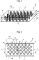
- FIG. 1 is a perspective view of chemical substance concentrator 10 in accordance with an exemplary embodiment.
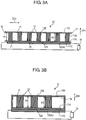
- FIG. 2 is a top view of chemical substance concentrator 10 for schematically showing an inside of chemical substance concentrator 10.
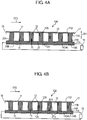
- FIG. 3A is a cross-sectional view of chemical substance concentrator 10 along line 3A-3A shown in FIG. 2 .
- FIG. 3B is a cross-sectional view of chemical substance concentrator 10 along line 3B-3B shown in FIG. 2 .
- Chemical substance concentrator 10 is configured to adsorb molecules of a chemical substance contained in a sample.
- the sample is, e.g. gas, such as exhaust gas, the living space air, or human exhalation.
- the chemical substance is, e.g. a volatile organic compound (VOC).
- Chemical substance concentrator 10 includes tubular body 11, adsorption part 12, and desorption part 94.
- Tubular body 11 has inlet 16 for taking the sample into an inside of tubular body 11, and has outlet 17 for discharging the sample to the outside of tubular body 11.
- Flow passage 13 is formed inside tubular body 11 such that the sample flows from inlet 16 to outlet 17 in flow direction D10 to allow the sample to pass through the flow passage 13.
- Tubular body 11 may have various shapes, such as a cylinder tube or a rectangular tube.
- Tubular body 11 shown in FIG. 1 has a cross section having a rectangular shape.
- tubular body 11 has inner surfaces 11A and 11B that face flow passage 13 and are opposed to each other, outer surface 11C that is opposite to inner surface 11A, and outer surface 11D that is opposite to inner surface 11B.
- Inner surfaces 11A and 11B constitute flow passage 13.
- flow passage 13 has a cross section having width W of 1 mm and height H1 of 30 ⁇ m.
- Flow passage 13 has length L of 10 mm.
- Tubular body 11 may be made of insulating material. Alternatively, tubular body 11 may be made of material having a surface which faces flow passage 13 and is covered with an insulator. Tubular body 11 may be made of, for example, insulators, such as glass, quartz, sapphire, or ceramic, or a silicon substrate having thermal silicon oxide formed on a surface thereof.
- insulators such as glass, quartz, sapphire, or ceramic, or a silicon substrate having thermal silicon oxide formed on a surface thereof.
- Inner surfaces 11A and 11B of tubular body 11 may be made of materials different from each other. In this case, a material forming tubular body 11 may be exposed from either one of inner surface 11A or inner surfaces 11B.
- Adsorption part 12 adsorbs molecules of a chemical substance contained in the sample.
- Plural adsorption parts 12 are provided on inner surface 11A of tubular body 11 to be spaced from one another with predetermined interval B1.
- Adsorption part 12 has a circular column shape.
- Adsorption part 12 has end 12A and end 12B opposite to end 12A. End 12A of adsorption part 12 is fixed onto inner surface 11A of tubular body 11.
- end 12B is provided on and fixed to inner surface 11B of tubular body 11.
- FIG. 3C is an enlarged view of chemical substance concentrator 10, and shows the periphery of adsorption part 12.
- Adsorption part 12 includes plural dense fibers 15. Fibers 15 forming adsorption part 12 increase a surface area of adsorption part 12.
- Sample A10 contains medium B10 of gas and molecules C10 of a chemical substance floating in medium B10.
- Adsorption part 12 is implemented by an aggregation of fibers 15 and has a surface with depressions and projections, thereby adsorbing molecules C10 of the chemical substance while rolling sample A10 (medium B10) of gas, as shown in FIG. 3C .
- Interval B1 (see FIG. 2 ) between adsorption parts 12 adjacent to each other in a cross section of tubular body 11 perpendicular to flow direction D10 is larger than interval D15 between fibers 15 in the cross section of tubular body 11.
- Fiber 15 has anisotropic properties.
- a layer for controlling a growing direction of fibers 15, a material layer serving as a core of fiber 15, and a catalyst layer are formed on inner surface 11A. After that, fibers 15 are grown by a vapor phase method or a liquid phase method. Fibers 15 are preferentially oriented in a direction substantially perpendicular to inner surface 11A.
- Fibers 15 are made of metal oxides, such as ZnO, SnO 2 , In 2 O 3 , In 2-x Sn x O 3 (for instance, 0.1 ⁇ x ⁇ 0.2), NiO, CuO, TiO 2 , and SiO 2 . Oxygen on a surface of the metal oxide interacts with molecules of the chemical substance, thereby adsorbing the molecules of the chemical substance efficiently.
- Fiber 15 is made of a nanowire or a nanofiber.
- Fiber 15 is covered with adsorption material 115 for adsorbing molecules of the chemical substance selectively.
- nickel and silver may be used as adsorption material 115.
- molybdenum may be used as adsorption material 115.
- zeolite may be used as adsorption material 115.
- palladium may be used as adsorption material 115.
- poly aniline may be used as adsorption material 115.
- adsorption material 115 In the case that molecules of a polar organic substance are adsorbed, a polyethylene glycol or PDMS (polydimethyl siloxane) may be used as adsorption material 115.
- adsorption material 115 is preferably made of a material having a surface having the same polarity as surfaces of the molecules. The material of adsorption material 115 can be selected according to the molecules of the chemical substance to be adsorbed as necessary.
- Fiber 15 may be made of adsorption material 115 for adsorbing molecules of the chemical substance selectively. If fiber 15 forming adsorption part 12 adsorbs molecules of the chemical substance by itself, fiber 15 may not be covered with adsorption material 115.
- an average diameter of adsorption part 12 is more than or equal to several tens micrometers and less than or equal to several hundred micrometers. In accordance with the embodiment shown in FIG. 2 , average diameter D1 of adsorption part 12 is approximately 200 ⁇ m.
- One adsorption part 112 out of plural adsorption parts 12 is spaced from another adsorption part 212 out of plural adsorption parts 12 which is adjacent to adsorption part 112 by an interval B1 of about 200 ⁇ m.
- Plural adsorption parts 12 are meanderingly arranged such that centers 12C of adsorption parts 12 which are located close to one another in flow direction D10 do not overlap one another viewing in flow direction D10.
- plural adsorption parts 12 are meanderingly arranged such that centers 12C of adsorption parts 12 adjacent to one another in flow direction D10 do not overlap viewing in flow direction D10.
- the sample passes through between plural adsorption parts 12 to flow from inlet 16 to outlet 17 in flow direction D10. At this moment, the sample hardly flows into between plural fibers 15 in single adsorption part 12. This is because a pressure loss within single adsorption part 12 is substantially three or four orders of magnitude larger than a pressure loss between plural adsorption parts 12 since fibers 15 are densely gathered in single adsorption part 12.
- height H2 of adsorption part 12 in height direction DH directed from inner surface 11A to inner surface 11B is 30 ⁇ m.
- Adsorption part 12 extends from inner surface 11A to inner surface 11B.
- height H1 of flow passage 13 in height direction DH is equal to height H2 of adsorption part 12, i.e., 30 ⁇ m in accordance with the embodiment.
- Desorption part 94 is provided on outer surface 11C of tubular body 11 opposite to inner surface 11A. Desorption part 94 desorbs the molecules of the chemical substance which has been adsorbed on adsorption part 12 from adsorption part 12 to return the desorbed molecules into the sample. Thus, chemical substance concentrator 10 can condense the chemical substance contained in the sample.
- the desorbed molecules of the chemical substance are detected by, for example, a sensor provided downstream in flow direction D10 with respect to chemical substance concentrator 10. Further, the adsorbed molecules of the chemical substance can be desorbed to recover the adsorbing function of adsorption part 12.
- desorption part 94 is implemented by heating unit 14 that is connected to external power source 18 and heats adsorption parts 12.
- Heating unit 14 in accordance with the embodiment is implemented by, e.g. a metal wire or a wiring pattern made of resistance heating material.
- heating unit 14 may be made of a NiCr thin film having a meandering shape.
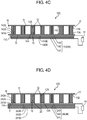
- FIG. 4A is a cross-sectional view of another chemical substance concentrator 10A in accordance with the embodiment.
- heating unit 14 serving as desorption part 94 is provided inside tubular body 11. Specifically, heating unit 14 is provided between tubular body 11 and each of adsorption parts 12. Insulating layer 20 is provided between heating unit 14 and each of adsorption parts 12. A current flowing in heating unit 14 can hardly flow into adsorption part 12. As a result, heating unit 14 can heat adsorption part 12 efficiently.
- Heating unit 14 has surface 14A and surface 14B opposite to surface 14A.
- Insulating layer 20 has surface 20A and surface 20B opposite to surface 20A.
- Surface 14B of heating unit 14 is provided on inner surface 11A of tubular body 11.
- Surface 20B of insulating layer 20 is provided on surface 14A of heating unit 14.
- Surface 20A of insulating layer 20 faces flow passage 13.
- end 12A of adsorption part 12 is provided on surface 20A of insulating layer 20.
- Insulating layer 20 is extremely thin, and thus allows adsorption part 12 to substantially contact heating unit 14.
- FIG. 4B is a cross-sectional view of still another chemical substance concentrator 10B in accordance with the embodiment.
- Chemical substance concentrator 10B shown in FIG. 4B does not include insulating layer 20 of chemical substance concentrator 10A shown in FIG. 4A .
- adsorption part 12 has dielectric properties.
- Surface 14A of heating unit 14 faces flow passage 13.
- ends 12A of adsorption parts 12 are provided on heating unit 14.
- Adsorption part 12 may not have dielectric properties.
- Adsorption part 12 implemented by an aggregation of fibers 15 has a small heat capacity depending on its structure.
- adsorption part 12 contacts heating unit 14 or substantially contacts heating unit 14, thereby heating adsorption part 12 efficiently and desorbing molecules C10 which have been adsorbed. Therefore, adsorption part 12 made of fibers 15 can desorb the chemical substance with little power consumption.
- Heating unit 14 may be made of material, such as a metal wire or a resistive heating material, generating heat.
- heating unit 14 includes heating sections A14 each facing respective one of adsorption parts 12 and connecting sections B14 for connecting heating sections A14 in series.
- each of heating sections A14 of heating unit 14 faces respective one of ends 12A of adsorption parts 12 across thin insulating layer 20, and substantially contacts respective one of ends 12A of adsorption parts 12.
- chemical substance concentrator 10B shown in FIG. 4B each of heating sections A14 of heating unit 14 contacts respective one of ends 12A of adsorption parts 12.
- Heating section A14 is made of a heat generating material that is patterned on a surface of end 12A of adsorption part 12, or a part of surface 20B of insulating layer 20 facing end 12A.
- the area of connecting section B14 is smaller than that of heating section A14. This configuration can heat only adsorption part 12. Thus, a cooling rate after the heating can be raised to adsorb and desorb molecules C10 of the chemical substance at high speed, thereby operating adsorption part 12 with small power consumption.
- FIG. 4C is a cross-sectional view of further chemical substance concentrator 10C in accordance with the embodiment.
- Chemical substance concentrator 10C includes heating unit 114 serving as desorption part 94 for heating adsorption part 12, instead of heating unit 14 of chemical substance concentrator 10 shown in FIG. 3A .
- Heating unit 114 includes lower electrode 141, nanofibers 142, and upper electrode 143.
- Nanofibers 142 are formed between lower electrode 141 and upper electrode 143. Nanofibers 142 have conductivity. Nanofibers 142 are electrically connected to lower electrode 141 and upper electrode 143.
- Lower electrode 141 and upper electrode 143 are connected to external power source 18.
- Upper electrode 143 is provided on outer surface 11C of tubular body 11.
- nanofibers 142 Upon having currents flow, nanofibers 142 generate heat due to resistances included in nanofibers 142. Accordingly, nanofibers 142 can be used as heating unit 14 of chemical substance concentrator 10 shown in FIG. 3A .
- Nanofibers 142 heat up heating unit 114 to a high temperature with little electric power. Therefore, adsorption part 12 can be heated efficiently with small electric power. Nanofibers 142 have a small heat capacity, and allow heating unit 114 to be cool at a high speed. Therefore, heating unit 114 using nanofiber 142 can heat or cool adsorption part 12 more quickly.
- Fibers 15 of adsorption part 12 and nanofibers 142 of heating unit 14 may be made of the same material. Alternatively, fibers 15 and nanofibers 142 may be formed of different materials.
- Chemical substance concentrators 10A and 10B shown in FIGs. 4A and 4B may include heating unit 114 shown in FIG. 4C , instead of heating unit 14.
- FIG. 4D is a cross-sectional view of further chemical substance concentrator 10D in accordance with the embodiment.
- Chemical substance concentrator 10D includes vibrator 24 serving as desorption part 94, instead of heating unit 14 of chemical substance concentrator 10A shown in FIG. 4A .
- vibrator 24 By vibrating adsorption part 12, vibrator 24 desorbs molecules C10 of the chemical substance adsorbed on adsorption part 12.
- Vibrator 24 has lower electrode 241, piezoelectric body 242, and upper electrode 243.
- Lower electrode 241 has surface 241A and surface 241B opposite to surface 241A.
- Piezoelectric body 242 has surface 242A and surface 242B opposite to surface 242A.
- Upper electrode 243 has surface 243A and surface 243B opposite to surface 243A.
- Piezoelectric body 242 is provided between lower electrode 241 and upper electrode 243.
- Surface 241B of lower electrode 241 is situated on inner surface 11A of tubular body 11.
- Surface 242B of piezoelectric body 242 is situated on surface 241A of lower electrode 241.
- Surface 243B of upper electrode 243 is situated on surface 242A of piezoelectric body 242.
- Insulating layers 20 are disposed on surface 243A of upper electrode 243. Ends 12B of adsorption parts 12 are bonded to surface 243A of upper electrode 243 via insulating layers 20.
- Piezoelectric body 242 is made of piezoelectric materials, such as Pb(Zr,Ti)O 3 (lead zirconate titanate) or AlN (aluminum nitride).
- FIG. 4E is a cross-sectional view of further chemical substance concentrator 10E in accordance with the embodiment.
- components identical to those of chemical substance concentrator 10D shown in FIG. 4D are denoted by the same reference numerals.
- Chemical substance concentrator 10E shown in FIG. 4E includes vibrator 124, instead of vibrator 24 of chemical substance concentrator 10D shown in FIG. 4D .
- adsorption parts 12 are provided on single vibrator 24.
- vibrator 124 has regions 124A to 124C separated from one another.
- Each of regions 124A to 124C of vibrator 124 includes lower electrode 241, piezo-electric body 242, and upper electrode 243. This configuration reduces a capacitance of each of regions 124A to 124C of vibrator 124, and increases resonance frequencies of regions 124A to 124C of vibrator 124, hence easily driving and vibrating regions 124A to 124C of vibrator 124 at a high frequency. Vibrator 124 can vibrate regions 124A to 124C at different frequencies or at different timings, so that the adsorbed molecules of a chemical substance can selectively be desorbed.
- FIG. 4F is a cross-sectional view of further chemical substance concentrators 10F in accordance with the embodiment.
- Chemical substance concentrator 10F includes light irradiation unit 34 functioning as desorption part 94, instead of heating unit 14 of chemical substance concentrator 10 shown in FIG. 3A .
- Light irradiation unit 34 is provided on outer surface 11D of tubular body 11.
- Light irradiation unit 34 irradiates adsorption part 12 with light so as to desorb molecules C10 of the chemical substance adsorbed on adsorption part 12.
- tubular body 11 may preferably be made of material, such as glass, having a high light-transmissible.
- a halogen lamp, a laser, a near-infrared lamp, an infrared lamp, and the like can be employed as light irradiation unit 34.
- Heating units 14 and 114, vibrators 24 and 124, and light irradiation unit 34 function as desorption part 94 for desorbing molecules C10 of the chemical substance adsorbed on adsorption part 12.
- Chemical substance concentrators 10, and 10A to 10F do not necessarily include desorption part 94.
- a current may flow to an electrode connected to fiber 15 of adsorption part 12.
- adsorption part 12 per se functions as a heating unit.
- adsorption part 12 may not necessarily have a circular column shape.
- adsorption part 12 may have an elliptic column shape or a polygonal column shape.
- Adsorption part 12 may have a conical shape, a pyramid shape, or an elliptic cone shape.
- FIG. 4G is a top view of further chemical substance concentrator 10G in accordance with the embodiment.
- components identical to those of chemical substance concentrator 10 shown in FIG. 2 are denoted by the same reference numerals.
- adsorption parts 12 are arranged at intervals in a row in flow direction D10 directed from inlet 16 to outlet 17 while centers 12C overlap in flow direction D10. This configuration reduces a pressure loss of fluid, and facilitates the sample to pass through flow passage 13 even if a pump with a small size and a low transport capacity is employed.
- carbon nanofiber is charged inside a tubular body as an adsorbent to provide an adsorption part.
- the charged adsorbent has a high density, a pressure loss of the adsorption part will be increased. For that reason, the sample hardly passes through the adsorption part.
- FIG. 4H is a cross-sectional view of further chemical substance concentrator 10H in accordance with the embodiment.
- adsorption parts 12 are arranged in a row without an interval in flow direction D10.
- adsorption parts 12 arranged along flow direction D10 are regarded as a single element.
- Interval D15 between adjacent fibers 15 arranged along flow direction D10 in the single element is smaller than interval B1 (see FIG. 2 ) between adsorption part 112 and adsorption part 212 in a direction perpendicular to flow direction D10.
- This configuration increases the density of adsorption part 12 while a pressure loss of fluid is reduced.
- the sample can efficiently be adsorbed on adsorption part 12.
- Adsorption part 12 may not necessarily be implemented by an aggregation of fibers 15.
- Adsorption part 12 may be made of a material, such as a porous body, having numerous micro-voids.
- the sample containing molecules of the chemical substance is inserted into chemical substance concentrator 10. Those molecules are adsorbed on adsorption parts 12 provided inside the flow passage.
- height H1 of flow passage 13 is 30 ⁇ m
- width W of flow passage 13 in a direction perpendicular to height H1 and flow direction D10 is 1 mm.
- the flow rate is 1 ml/min
- chemical substance concentrator 10 has a pressure loss of about 3.2 kPa
- the Reynolds number is 4.9.
- the flow rate is 5 ml/min
- chemical substance concentrator 10 has a pressure loss of about 16 kPa
- the Reynolds number is 24.7.
- the flow rate is 10 ml/min
- chemical substance concentrator 10 has a pressure loss of about 31.9 kPa
- the Reynolds number is 49.3.
- a small sized pump with a maximum static pressure of 80kPa can be used to insert the sample into chemical substance concentrator 10.
- a comparative example of a chemical substance concentrator in which adsorption part 12 is provided over the entire cross section of the flow passage will be described below.
- a pressure loss of the chemical substance concentrator is more than about 100000 kPa. For that reason, a small sized pump with a small capacity can hardly insert the sample into the chemical substance concentrator of the comparative example.
- inserted sample A10 flows so as to flow around adsorption part 12 as a laminar flow, and flows along flow passage 13.
- vortexes are produced around adsorption part 12 due to sub-micron to micron-sized depressions and projections caused by fibers 15 constituting adsorption part 12.
- Heavy substances, such as VOC, contained in the sample receive a centrifugal force due to the vortexes and hit fibers 15, so that adsorption part 12 can adsorb molecules more effectively than a typical adsorption part having a circular column shape.
- the Reynolds number is preferably smaller than 3000. This configuration allows sample A10 to flow behind adsorption part 12 as a laminar flow.
- the Reynolds number is preferably smaller than 150. This configuration prevents a Karman vortex from being produced behind adsorption part 12. Accordingly, sample A10 also flows around behind adsorption part 12, so that more molecules C10 of the chemical substance are adsorbed.
- FIG. 5 is a side cross-sectional view of further chemical substance concentrator 30 in accordance with the embodiment.
- components identical to those of chemical substance concentrator 10 shown in FIGs. 1 to 3C are denoted by the same reference numerals.
- Chemical substance concentrator 30 is different from chemical substance concentrator 10 in that a space is provided above adsorption part 12.
- the other structures are the same as chemical substance concentrator 10.
- Chemical substance concentrator 30 includes tubular body 11 and adsorption parts 12 provided on inner surface 11A of tubular body 11. End 12B of adsorption part 12 is provided on inner surface 11A while end 12A faces inner surface 11B with an interval between end 12B and inner surface 11B.
- a space through which the sample flows is formed above adsorption part 12, i.e., between end 12A of adsorption part 12 and inner surface 11B.
- Adsorption section 12 does not contact inner surface 11B.
- chemical substance concentrator 30 has a two-layer structure, i.e., region 31 in which adsorption part 12 is formed and region 32 in which adsorption part 12 is not formed.
- the pressure loss of chemical substance concentrator 30 can be calculated in the state a flow passage in which adsorption part 12 is formed and a flow passage in which adsorption part 12 is not formed are connected in parallel.
- a pressure loss of region 31 in which adsorption part 12 is formed is larger than a pressure loss of region 32 in which adsorption part 12 is not formed. If a difference between the pressure losses of region 31 and region 32 increases, the sample hardly flow into region 31 in which adsorption part 12 is formed. For that reason, the pressure loss of region 31 is preferably identical to the pressure loss of region 32, or the difference between the pressure losses of regions 31 and 32 is about one digit order.
- FIG. 6 is a side cross-sectional view of further chemical substance concentrator 30A in accordance with the embodiment.
- adsorption part 12 inclines so as to extend toward inlet 16 of flow passage 13.
- End 15B of fiber 15 is disposed on inner surface 11A.
- End 15A of fiber 15 is located closer to inlet 16 of flow passage 13 than end 15B of fiber 15 is.
- fiber 15 extends from inner surface 11A and inclines at an acute angle with respect to flow direction D10 of the sample. That is, ends 12B of adsorption parts 12 are located more downstream in flow direction D10 of the sample than ends 12A.
- the sample also enters between fibers 15 of adsorption part 12 easily. For that reason, molecules of the chemical substance are adsorbed not only on end 12A, which is an upper surface of adsorption part 12, but also on fibers 15 located inside adsorption part 12.
- Fibers 15 inclining toward inlet 16 are made of crystal fibers.
- a crystal layer is formed as a core of fiber 15.
- the crystal layer is formed by sputtering, such as PVD (Physical Vapor Deposition).
- Vaper-deposited particles formed by sputtering flow over a wide solid angle.
- a c-axis direction of the obtained columnar crystal grows with dispersion from an axis perpendicular to a substrate surface. The dispersion strongly depends on a flowing angle of the particles.
- a target is offset, and a region directly above a target erosion part is masked with a shielding plate. Accordingly, the sputtering apparatus sputters particles to prevent the particles from flowing in a vertical component thereof. As a result, a crystal layer of a columnar crystal oriented in the c-axis inclining in one direction with respect to the substrate surface is obtained.
- the fibers are formed on the formed crystal layer by a vapor phase method or a liquid phase method, thereby obtaining fibers 15 inclining with respect to the substrate surface.
- inner surface 11A of tubular body 11 is used as a flat surface of the substrate, fibers 15 can be formed to incline at any angle with respect to flow direction D10. The angle ranges, for example, from 45 degree to 80 degree.
- FIG. 7 is a side cross-sectional view of further chemical substance concentrator 40 in accordance with the embodiment.
- inlet 16 of flow passage 13 may be provided above adsorption part 12.
- fibers 15 of adsorption part 12 extend perpendicularly from surface 14A toward inlet 16.
- flow direction D40 in which the sample flows has a component directed from end 12A to end 12B of adsorption part 12, and inclines with respect to adsorption part 12.
- FIG. 8 is a side cross-sectional view of further chemical substance concentrator 40A in accordance with the embodiment.
- components identical to those of chemical substance concentrator 40 shown in FIG. 7 are denoted by the same reference numerals.
- flow passage 13 of inlet 16 inclines at an angle with respect to adsorption part 12.
- inlet 16 is provided above a portion of inner surface 11A having adsorption part 12 thereon closer to inlet 16.
- Adsorption part 12 may incline relatively with respect to flow passage 13.
- flow direction D40A in which the sample flows has a component directed from end 12A to end 12B of adsorption part 12, and inclines with respect to adsorption part 12.
- the sample can enter between fibers 15 of adsorption part 12.
- Chemical substance concentrators 40 and 40A can adsorb chemical molecules efficiently.
- chemical substance concentrator 10 (10A to 10H, 30, 30A, 40, and 40A) includes tubular body 11 and adsorption parts 12 provided in an inside of tubular body 11.
- Tubular body 11 forms flow passage 13 through which sample A10 containing a chemical substance flows in flow direction D10.
- Adsorption parts 12 adsorb the chemical substance, and desorb the adsorbed chemical substance.
- Adsorption part 12 is an aggregation of fibers 15 made of metal oxide.
- adsorption parts 12 are arranged to be spaced from one another by interval B1.
- interval B1 between adsorption parts 12 adjacent to each other among adsorption parts 12 may be larger than interval D1 between fibers 15 in adsorption part 12.
- Tubular body 11 may have inner surface 11A on which adsorption parts 12 are provided, and inner surface 11B that faces inner surface 11A of tubular body 11 and is separated from adsorption parts 12.
- End 12A of adsorption part 12 may be located more downstream in flow direction D10 than end 12B .
- Fibers 15 may be made of ZnO.
- Desorption part 94 desorbs, from adsorption parts 12, the chemical substance adsorbed on adsorption parts 12.
- Desorption part 94 may be heating unit 14 for heating adsorption parts 12.
- Desorption part 94 may be vibrator 24 for vibrating adsorption parts 12.
- Desorption part 94 may be light irradiation unit 34 for irradiating adsorption parts 12 with light.
- Adsorption parts 12 may be arranged meanderingly.
- Adsorption parts 12 may be arranged in a row.
- Adsorption parts 12 may be arranged in a row without an interval in a cross section of tubular body 11 other than the above-mentioned cross section.
- Adsorption parts 12 may desorb the adsorbed chemical substance into sample A10.
- Chemical substance concentrators 10, 10A to 10H, 30, 30A, 40, and 40A may be formed inside a pipe provided in a detection system, for example.
- the pipe of the detection system serves as tubular body 11.
Landscapes
- Chemical & Material Sciences (AREA)
- Analytical Chemistry (AREA)
- Chemical Kinetics & Catalysis (AREA)
- Engineering & Computer Science (AREA)
- Health & Medical Sciences (AREA)
- Life Sciences & Earth Sciences (AREA)
- General Health & Medical Sciences (AREA)
- Pathology (AREA)
- Immunology (AREA)
- General Physics & Mathematics (AREA)
- Physics & Mathematics (AREA)
- Biochemistry (AREA)
- Organic Chemistry (AREA)
- General Chemical & Material Sciences (AREA)
- Oil, Petroleum & Natural Gas (AREA)
- Molecular Biology (AREA)
- Biomedical Technology (AREA)
- Inorganic Chemistry (AREA)
- Materials Engineering (AREA)
- Nanotechnology (AREA)
- Crystallography & Structural Chemistry (AREA)
- Electrochemistry (AREA)
- Sampling And Sample Adjustment (AREA)
- Solid-Sorbent Or Filter-Aiding Compositions (AREA)
- Separation Of Gases By Adsorption (AREA)
- Treating Waste Gases (AREA)
Applications Claiming Priority (2)
| Application Number | Priority Date | Filing Date | Title |
|---|---|---|---|
| JP2015091689 | 2015-04-28 | ||
| PCT/JP2016/002192 WO2016174866A1 (fr) | 2015-04-28 | 2016-04-26 | Condenseur de substance chimique |
Publications (2)
| Publication Number | Publication Date |
|---|---|
| EP3290900A1 true EP3290900A1 (fr) | 2018-03-07 |
| EP3290900A4 EP3290900A4 (fr) | 2018-04-18 |
Family
ID=57198370
Family Applications (1)
| Application Number | Title | Priority Date | Filing Date |
|---|---|---|---|
| EP16786143.4A Withdrawn EP3290900A4 (fr) | 2015-04-28 | 2016-04-26 | Condenseur de substance chimique |
Country Status (4)
| Country | Link |
|---|---|
| US (1) | US20180052083A1 (fr) |
| EP (1) | EP3290900A4 (fr) |
| JP (1) | JP6834947B2 (fr) |
| WO (1) | WO2016174866A1 (fr) |
Cited By (1)
| Publication number | Priority date | Publication date | Assignee | Title |
|---|---|---|---|---|
| EP3655132A4 (fr) * | 2017-07-18 | 2020-07-22 | Environmental Management Confederation Inc. | Conception de supports de filtre adsorbant incliné dans des applications de flux tangentiel |
Families Citing this family (8)
| Publication number | Priority date | Publication date | Assignee | Title |
|---|---|---|---|---|
| US11169059B2 (en) * | 2016-10-31 | 2021-11-09 | Panasonic Corporation | Chemical substance concentrator and chemical substance detection device |
| WO2018180794A1 (fr) * | 2017-03-28 | 2018-10-04 | 富士フイルム株式会社 | Procédé de détection de gaz, système de détection de gaz et procédé de désorption de gaz |
| CN109513311B (zh) * | 2019-01-16 | 2022-03-04 | 上海环境保护有限公司 | 一种实现高效节能的动态流化床分级吸附的废气处理方法 |
| US11352884B2 (en) * | 2019-06-17 | 2022-06-07 | Halliburton Energy Services, Inc. | Downhole hydrogen sulfide capture and measurement |
| EP3872487B1 (fr) | 2020-02-25 | 2022-10-05 | Carrier Corporation | Dispositif de détection d'alcène volatil et procédé d'utilisation |
| EP4082434A1 (fr) * | 2021-04-28 | 2022-11-02 | Merck Patent GmbH | Dispositif prélèvement d'air ou d'haleine capturant des fractions d'aérosol et de vapeur |
| JP7593300B2 (ja) * | 2021-11-09 | 2024-12-03 | 株式会社豊田中央研究所 | 濃縮器 |
| JP7471657B2 (ja) | 2021-11-24 | 2024-04-22 | 国立大学法人鳥取大学 | 呼気捕獲装置 |
Family Cites Families (13)
| Publication number | Priority date | Publication date | Assignee | Title |
|---|---|---|---|---|
| EP1179585B1 (fr) * | 1997-12-24 | 2008-07-09 | Cepheid | Dispositif et procédé de Lyse |
| JP2003002621A (ja) * | 2001-06-21 | 2003-01-08 | Mitsubishi Electric Corp | 六弗化硫黄ガス回収装置 |
| US8152991B2 (en) * | 2005-10-27 | 2012-04-10 | Nanomix, Inc. | Ammonia nanosensors, and environmental control system |
| US7910064B2 (en) * | 2003-06-03 | 2011-03-22 | Nanosys, Inc. | Nanowire-based sensor configurations |
| US20100227382A1 (en) * | 2005-05-25 | 2010-09-09 | President And Fellows Of Harvard College | Nanoscale sensors |
| JP2007125458A (ja) * | 2005-11-01 | 2007-05-24 | Sharp Corp | 空気調和機の有害化学ガス除去方法、空気調和機、および有害化学ガス除去フィルタ |
| KR100812357B1 (ko) * | 2005-12-23 | 2008-03-11 | 한국과학기술연구원 | 초고감도 금속산화물 가스센서 및 그 제조방법 |
| JP2009023881A (ja) * | 2007-07-20 | 2009-02-05 | Panasonic Corp | カーボンナノチューブおよびカーボンナノチューブ構造体 |
| KR101201897B1 (ko) * | 2008-12-12 | 2012-11-16 | 한국전자통신연구원 | 산화물 반도체 나노섬유를 이용한 초고감도 가스센서 및 그제조방법 |
| CN102714137B (zh) * | 2009-10-16 | 2015-09-30 | 康奈尔大学 | 包括纳米线结构的方法和装置 |
| US20120301360A1 (en) * | 2011-05-26 | 2012-11-29 | Lockheed Martin Corporation | Nanostructured aerogel-thermoelectric device, making and using the same |
| WO2013175503A2 (fr) * | 2012-05-22 | 2013-11-28 | Nanosniff Technologies Pvt. Ltd. | Pré-concentrateur mems basé sur une nanostructure |
| JP6227934B2 (ja) * | 2013-08-23 | 2017-11-08 | 株式会社Nttドコモ | ガスの測定装置及びガスの測定方法 |
-
2016
- 2016-04-26 WO PCT/JP2016/002192 patent/WO2016174866A1/fr not_active Ceased
- 2016-04-26 EP EP16786143.4A patent/EP3290900A4/fr not_active Withdrawn
- 2016-04-26 US US15/555,207 patent/US20180052083A1/en not_active Abandoned
- 2016-04-26 JP JP2017515390A patent/JP6834947B2/ja active Active
Cited By (2)
| Publication number | Priority date | Publication date | Assignee | Title |
|---|---|---|---|---|
| EP3655132A4 (fr) * | 2017-07-18 | 2020-07-22 | Environmental Management Confederation Inc. | Conception de supports de filtre adsorbant incliné dans des applications de flux tangentiel |
| US11524257B2 (en) | 2017-07-18 | 2022-12-13 | Environmental Management Confederation, Inc. | Angled adsorbent filter media design in tangential flow applications |
Also Published As
| Publication number | Publication date |
|---|---|
| WO2016174866A1 (fr) | 2016-11-03 |
| US20180052083A1 (en) | 2018-02-22 |
| JP6834947B2 (ja) | 2021-02-24 |
| EP3290900A4 (fr) | 2018-04-18 |
| JPWO2016174866A1 (ja) | 2018-02-22 |
Similar Documents
| Publication | Publication Date | Title |
|---|---|---|
| EP3290900A1 (fr) | Condenseur de substance chimique | |
| CN107683407B (zh) | 化学物质检测装置 | |
| US7531027B2 (en) | Contaminant extraction systems, methods, and apparatuses | |
| US10948392B2 (en) | Airborne particle detection system with thermophoretic scanning | |
| US6914220B2 (en) | Microelectromechanical heating apparatus and fluid preconcentrator device utilizing same | |
| CN109690280B (zh) | 化学物质浓缩器以及化学物质检测装置 | |
| TWI612286B (zh) | 用於檢測導電性和/或可極化粒子的感測器、感測系統、操作感測器的方法、此感測器的製造方法及此感測器的應用(二) | |
| CN105283756B (zh) | 气体检测装置及其方法 | |
| US12403418B2 (en) | Nanoporous metal foam gas and fluid filters | |
| KR20100087315A (ko) | 플라즈마-증착된 미공성 층을 포함하는 유기 화학적 센서와, 제조 및 사용 방법 | |
| JP2019527365A (ja) | ガス採取用カテーテル | |
| JP2010504854A (ja) | ナノワイヤフィルタ、その製造方法および吸着物除去方法、これを具備したフィルタ装置 | |
| CN108136314B (zh) | 化学物质浓缩器以及化学物质检测器 | |
| CN114651178A (zh) | 气体测量装置和方法 | |
| JP2017106857A (ja) | 半導体式ガスセンサ、半導体式ガスセンサの製造方法、およびセンサネットワークシステム | |
| JP6113593B2 (ja) | 空気清浄化装置および空気清浄化方法 | |
| US9352246B2 (en) | Evaporation device | |
| JP2009142808A (ja) | 排ガス浄化装置 | |
| JP2009112916A (ja) | 排ガス浄化装置 | |
| JP2015020094A (ja) | 空気清浄化装置および空気清浄化方法 | |
| CN112107958A (zh) | 等离子体再生组件、具有其的空气净化装置和空调系统 | |
| CN112113285A (zh) | 等离子体再生组件、具有其的空气净化装置和空调系统 | |
| JP2007248323A (ja) | 分子検出センサ | |
| CN114733099B (zh) | 鼻塞式呼吸器 | |
| KR101539560B1 (ko) | 탄소나노튜브 폼, 이의 제조방법 및 이를 이용한 마이크로 전농축기 모듈 |
Legal Events
| Date | Code | Title | Description |
|---|---|---|---|
| PUAI | Public reference made under article 153(3) epc to a published international application that has entered the european phase |
Free format text: ORIGINAL CODE: 0009012 |
|
| 17P | Request for examination filed |
Effective date: 20171017 |
|
| AK | Designated contracting states |
Kind code of ref document: A1 Designated state(s): AL AT BE BG CH CY CZ DE DK EE ES FI FR GB GR HR HU IE IS IT LI LT LU LV MC MK MT NL NO PL PT RO RS SE SI SK SM TR |
|
| AX | Request for extension of the european patent |
Extension state: BA ME |
|
| A4 | Supplementary search report drawn up and despatched |
Effective date: 20180319 |
|
| RIC1 | Information provided on ipc code assigned before grant |
Ipc: B01D 53/04 20060101ALI20180313BHEP Ipc: G01N 1/22 20060101AFI20180313BHEP |
|
| DAV | Request for validation of the european patent (deleted) | ||
| DAX | Request for extension of the european patent (deleted) | ||
| STAA | Information on the status of an ep patent application or granted ep patent |
Free format text: STATUS: THE APPLICATION IS DEEMED TO BE WITHDRAWN |
|
| 18D | Application deemed to be withdrawn |
Effective date: 20181020 |