EP3290903B1 - Procédé et dispositif de test d'usure abrasive - Google Patents
Procédé et dispositif de test d'usure abrasive Download PDFInfo
- Publication number
- EP3290903B1 EP3290903B1 EP16786217.6A EP16786217A EP3290903B1 EP 3290903 B1 EP3290903 B1 EP 3290903B1 EP 16786217 A EP16786217 A EP 16786217A EP 3290903 B1 EP3290903 B1 EP 3290903B1
- Authority
- EP
- European Patent Office
- Prior art keywords
- rubber sample
- contact member
- rubber
- scratch abrasion
- sample
- Prior art date
- Legal status (The legal status is an assumption and is not a legal conclusion. Google has not performed a legal analysis and makes no representation as to the accuracy of the status listed.)
- Active
Links
Images


Classifications
-
- G—PHYSICS
- G01—MEASURING; TESTING
- G01N—INVESTIGATING OR ANALYSING MATERIALS BY DETERMINING THEIR CHEMICAL OR PHYSICAL PROPERTIES
- G01N3/00—Investigating strength properties of solid materials by application of mechanical stress
- G01N3/56—Investigating resistance to wear or abrasion
-
- G—PHYSICS
- G01—MEASURING; TESTING
- G01N—INVESTIGATING OR ANALYSING MATERIALS BY DETERMINING THEIR CHEMICAL OR PHYSICAL PROPERTIES
- G01N3/00—Investigating strength properties of solid materials by application of mechanical stress
- G01N3/02—Details
-
- G—PHYSICS
- G01—MEASURING; TESTING
- G01N—INVESTIGATING OR ANALYSING MATERIALS BY DETERMINING THEIR CHEMICAL OR PHYSICAL PROPERTIES
- G01N2203/00—Investigating strength properties of solid materials by application of mechanical stress
- G01N2203/003—Generation of the force
- G01N2203/0032—Generation of the force using mechanical means
- G01N2203/0033—Weight
-
- G—PHYSICS
- G01—MEASURING; TESTING
- G01N—INVESTIGATING OR ANALYSING MATERIALS BY DETERMINING THEIR CHEMICAL OR PHYSICAL PROPERTIES
- G01N2203/00—Investigating strength properties of solid materials by application of mechanical stress
- G01N2203/003—Generation of the force
- G01N2203/005—Electromagnetic means
-
- G—PHYSICS
- G01—MEASURING; TESTING
- G01N—INVESTIGATING OR ANALYSING MATERIALS BY DETERMINING THEIR CHEMICAL OR PHYSICAL PROPERTIES
- G01N2203/00—Investigating strength properties of solid materials by application of mechanical stress
- G01N2203/02—Details not specific for a particular testing method
- G01N2203/022—Environment of the test
- G01N2203/0222—Temperature
- G01N2203/0226—High temperature; Heating means
-
- G—PHYSICS
- G01—MEASURING; TESTING
- G01N—INVESTIGATING OR ANALYSING MATERIALS BY DETERMINING THEIR CHEMICAL OR PHYSICAL PROPERTIES
- G01N2203/00—Investigating strength properties of solid materials by application of mechanical stress
- G01N2203/02—Details not specific for a particular testing method
- G01N2203/026—Specifications of the specimen
- G01N2203/0262—Shape of the specimen
- G01N2203/0278—Thin specimens
- G01N2203/0282—Two dimensional, e.g. tapes, webs, sheets, strips, disks or membranes
-
- G—PHYSICS
- G01—MEASURING; TESTING
- G01N—INVESTIGATING OR ANALYSING MATERIALS BY DETERMINING THEIR CHEMICAL OR PHYSICAL PROPERTIES
- G01N2203/00—Investigating strength properties of solid materials by application of mechanical stress
- G01N2203/02—Details not specific for a particular testing method
- G01N2203/06—Indicating or recording means; Sensing means
- G01N2203/0641—Indicating or recording means; Sensing means using optical, X-ray, ultraviolet, infrared or similar detectors
-
- G—PHYSICS
- G01—MEASURING; TESTING
- G01N—INVESTIGATING OR ANALYSING MATERIALS BY DETERMINING THEIR CHEMICAL OR PHYSICAL PROPERTIES
- G01N2203/00—Investigating strength properties of solid materials by application of mechanical stress
- G01N2203/02—Details not specific for a particular testing method
- G01N2203/06—Indicating or recording means; Sensing means
- G01N2203/067—Parameter measured for estimating the property
- G01N2203/0676—Force, weight, load, energy, speed or acceleration
-
- G—PHYSICS
- G01—MEASURING; TESTING
- G01N—INVESTIGATING OR ANALYSING MATERIALS BY DETERMINING THEIR CHEMICAL OR PHYSICAL PROPERTIES
- G01N2203/00—Investigating strength properties of solid materials by application of mechanical stress
- G01N2203/02—Details not specific for a particular testing method
- G01N2203/06—Indicating or recording means; Sensing means
- G01N2203/067—Parameter measured for estimating the property
- G01N2203/0682—Spatial dimension, e.g. length, area, angle
-
- G—PHYSICS
- G01—MEASURING; TESTING
- G01N—INVESTIGATING OR ANALYSING MATERIALS BY DETERMINING THEIR CHEMICAL OR PHYSICAL PROPERTIES
- G01N2203/00—Investigating strength properties of solid materials by application of mechanical stress
- G01N2203/02—Details not specific for a particular testing method
- G01N2203/06—Indicating or recording means; Sensing means
- G01N2203/067—Parameter measured for estimating the property
- G01N2203/0694—Temperature
Definitions
- the present invention relates to a scratch abrasion tester and testing method and particularly relates to a scratch abrasion tester and testing method that can accurately estimate the scratch abrasion resistance of an upper cover rubber of a conveyor belt when actually used.
- Various objects including mineral resources such as iron ore and limestone, are conveyed by a conveyor belt.
- the objects to be conveyed are fed onto an upper cover rubber of the conveyor belt from a hopper or another conveyor belt.
- the fed objects to be conveyed are loaded on the upper cover rubber and conveyed in a running direction of the conveyor belt.
- the upper cover rubber is subject to impact, and when the surfaces of the objects to be conveyed are sharp, the upper cover rubber sometimes sustains cut damage.
- testers for evaluating the wear resistance of rubber include the DIN abrasion tester and the Williams abrasion tester. These abrasion testers are not for obtaining the amount of scratch abrasion. Thus, there is a demand for a tester with a novel configuration for accurately estimating the scratch abrasion resistance of an upper cover rubber of a conveyor belt when actually used.
- US 2005/050942 A1 discloses a wear test system for monitoring wear of a sample including a test material located on a base surface of a contrasting color.
- a sample is stationary disposed on a sample mounting surface of the wear test system.
- Brush type scrub devices are scrubbed on the base surface of the sample.
- a wear of the "brushed" upper surface of the sample is detected by means of cameras, which view the surface from above along a vertical direction.
- US 6 199 424 B1 discloses a friction testing apparatus for measuring friction characteristics between a test sample and a friction surface.
- the friction testing apparatus comprises an annular friction element which is moved rotatably. A test sample is held stationary in contact with the upper surface of the annular friction element. Weights mounted at a weight platform press the sample against the upper surface of the annular friction element. The weight of the weights determine the pressure with which the friction generating mechanical contact between the sample and the annular friction element is generated.
- JP 2004 020 319 A discloses an abrasion test apparatus comprising a test conveyor belt being stretched between a pair of pulleys.
- One of the pulleys is driven by an electric motor.
- the speed of the test conveyor belt can be set by changing the rotational speed of the electric motor M.
- the other one of the pulleys can be shifted perpendicular to its axial extension by means of a tension applying means in order to apply a predetermined tension to the test conveyor belt.
- the test conveyor belt is provided with elastic cover materials such as rubber on both sides of a canvas as a core material.
- An abrasion is generated with a vibrating indenter being located below the lower portion of the test conveyor belt. By varying the area of a top surface of the indenter, the impact force per unit area can be changed when the indenter collides with the test conveyor belt 1.
- JP 2011 257 187 A discloses a system and a method for evaluating an impact resistance of a conveyor belt.
- a weight is freely dropped at a drop position onto a test sample.
- An impact force sensor being arranged between the weight and a tipped collision element is used for detecting the impact force.
- the impact force causes a tension of a core body at which the test sample CV is formed.
- the tension is measured by means of a tension sensor.
- An object of the present invention is to provide a scratch abrasion tester and testing method that accurately estimate the scratch abrasion resistance of an upper cover rubber of a conveyor belt when actually used.
- a scratch abrasion tester as defined with claim 1 is provided.
- the running speed of the rubber sample and the pressing load applied by the contact member can be set as desired.
- the contact member with the desired tip specification can be pressed against the surface of the rubber sample.
- evaluation under similar conditions to that of the actual usage environment of the conveyor belt can be performed. Accordingly, the scratch abrasion resistance of the upper cover rubber of the conveyor belt when actually used can be accurately estimated. Additionally, the effects of tension on the scratch abrasion resistance of the conveyor belt can also be determined.
- the amount of scratch abrasion of the rubber sample for a discretionary period can be quickly determined. Additionally, the amount of scratch abrasion of the rubber sample can be determined without removing the rubber sample from the pair of pulleys.
- the support portion that supports an inner surface of the belt member being disposed between the pair of pulleys, and the contact member being pressed against the surface of the rubber sample at a position where the support portion supports the belt member and a position where the belt member is not supported, the effect of the support portion on the scratch abrasion resistance can be determined. Accordingly, the scratch abrasion resistance of the upper cover rubber of the conveyor belt when actually used can be more accurately estimated.
- the scratch abrasion tester can further comprise a load sensor configured to successively detect the pressing load acting on the contact member and a load in a running direction of the rubber sample acting on the contact member. As a result, the kinetic friction coefficient of the rubber sample can be determined.
- a temperature control mechanism that can vary an external environment temperature of the rubber sample can also be provided. This allows the external environment temperature of the rubber sample to be set to the desired temperature, allowing the evaluation to be performed under conditions even more similar to that of the actual usage environment of the conveyor belt.
- a temperature sensor that detects a surface temperature of the rubber sample can be provided. This allows the change in surface temperature of the rubber sample during evaluation to be measured and the energy produced by abrasion of the rubber sample to be determined.
- objects to be conveyed S is conveyed by a conveyor belt 18, fed onto a conveyor belt 12, and conveyed to a conveying destination by the conveyor belt 12.
- the objects to be conveyed S may be fed onto the conveyor belt 12 by a hopper and the like.
- the conveyor belt 12 is stretched at a prescribed tension between pulleys 16a and 16b.
- the conveyor belt 12 includes a core layer 13 including a core made of canvas, steel cord, or the like, and an upper cover rubber 14 and a lower cover rubber 15 that sandwich the core layer 13 therebetween.
- the core layer 13 is the member that bears the tension that causes the conveyor belt 12 to be stretched.
- the lower cover rubber 15 is supported by support rollers 17 on a carrier side of the conveyor belt 12, and the upper cover rubber 14 is supported by support rollers 17 on a return side of the conveyor belt 12.
- Three support rollers 17 are arranged on the carrier side of the conveyor belt 12 in the belt width direction.
- the conveyor belt 12 is supported by the support rollers 17 in a recessed manner at a prescribed trough angle a.
- the pulley 16a on a drive side is rotationally driven, the conveyor belt 12 runs in one direction at a prescribed running speed V.
- the objects to be conveyed S are fed onto the upper cover rubber 14, and are loaded on the upper cover rubber 14 and conveyed.
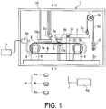
- a scratch abrasion tester 1 (hereinafter referred to as tester 1) according to an embodiment of the present invention illustrated in FIGS. 1 and 2 includes a pair of pulleys 7a, 7b, a contact member 4, an arm portion 3 to which the contact member 4 is removably attached, at least one anchor member 5 removably attached to the arm portion 3, and a control unit 6a.
- the tester 1 further includes a shape sensor 9a, a calculation unit 11, a support portion 17a, a load sensor 9b, a temperature sensor 9c, a heating plate 10a, and a casing 10 in which the components described above except for the control unit 6a and the calculation unit 11 are disposed.
- the heating plate 10a is wider than a rubber sample R and can heat the rubber sample R to a desired temperature and maintain the rubber sample R at this temperature.
- the heating plate 10a when a configuration is provided in which the casing 10 functions, as a thermostatic chamber for maintaining the interior thereof at a desired temperature to set the rubber sample R to the desired temperature, the heating plate 10a can be omitted.
- the interior of the casing 10 in addition to temperature, can be set to and maintained at a desired humidity.
- the pulleys 7a, 7b are supported by support stands 8 disposed in an upright manner on a base 2a. At least one of the pulleys 7a, 7b can move horizontally so that the distance between the pulleys 7a, 7b is variable.
- the pulley 7a is driven in rotation by a drive motor 6.
- the pulley 7b freely rotates.
- the rotational speed of the pulley 7a is variable and can be set to a desired speed.
- the rotational speed is controlled by the control unit 6a.
- the pulley 7a and the drive motor 6 can have a configuration in which driving force is transferred via a transferring mechanism including a gear or a belt.
- An annular belt member B is stretched between the pulleys 7a, 7b.
- the rubber sample R is fixed to the outer surface of the belt member B.
- a recessed portion is provided in the outer surface of the belt member B, and the rubber sample R fits in the recessed portion.
- the outer surface of the belt member B and the rubber sample R may be integrally formed via the friction therebetween or may be integrally formed via an adhesive applied thereto.
- the rubber sample R may be vulcanization-bonded to the outer surface of the belt member B for integration with the belt member B.
- the flat plate-like support portion 17a is disposed between the pulleys 7a, 7b to support the inner surface of the belt member B.
- the support portion 17a is an optional member that may be provided as necessary.
- the arm portion 3 is supported on a post 2b disposed in an upright manner on the base 2a by a rotation shaft 3b, allowing for pivotal movement in the vertical direction.
- a pin 5c is provided on the arm portion 3 at a first end portion in the longitudinal direction.
- the pin 5c and the anchor member 5 are connected by a wire 5a that runs through a pulley 5b.
- the arm portion 3, the wire 5a, and the pulley 5b constitute a pressing mechanism described below that presses the contact member 4 against the surface of the rubber sample R.
- the contact member 4 is attached to the arm portion 3 in a manner allowing the contact member 4 to be brought into contact with the surface of the rubber sample R. Specifically, the contact member 4 is removably attached to a holding portion 3a fixed to the arm portion 3 at a second end portion in the longitudinal direction.
- contact members 4 are provided with different specifications (shape, hardness, material, and the like) for the tip that comes into contact with the surface of the rubber sample R.
- the contact members 4 (4a, 4b, 4c) have a contact surface with specifications similar to that of the objects to be conveyed S that are conveyed by the conveyor belt 12 that includes the upper cover rubber 14 with similar specifications to the rubber sample R.
- the sharpness, hardness, and the like of the objects to be conveyed S varies depending on the type of objects, such as iron ore or other fragmented rocks. Therefore, various types of contact members 4 having contact surfaces imitating these types of objects are provided.
- the desired contact member 4 can be selected from the various types of contact members 4 (4a, 4b, 4c) and attached to the holding portion 3a.
- the at least one anchor member 5 is removably attached to one end portion of the wire 5a.
- the number and types of the attached anchor members 5 can be changed as appropriate.
- the load of the anchor member or members 5 lifts up the pin 5c connected to the wire 5a, and the arm portion 3 pivots in the vertical direction about the rotation shaft 3b located partway along the arm portion 3 in the longitudinal direction. This action presses the contact member 4 against the surface of the rubber sample R.
- the arm portion 3, the wire 5a, and the pulley 5b constitute the pressing mechanism, however, any pressing mechanism can be used that presses the contact member 4 against the surface of the rubber sample R.
- the distances of the contact member 4 and the pin 5c from the rotation shaft 3b are changed, so that the pressure at which the contact member 4 presses against the rubber sample R can be adjusted.
- the at least one anchor member 5 may be any member that can change the pressing load of the contact member 4 against the rubber sample R. In other words, depending on the weight of the at least one anchor member 5, the pressure at which the contact member 4 presses against the surface of the rubber sample R can be changed.
- the shape sensor 9a is attached to the casing 10, for example, and detects the cross-sectional shape of the surface of the rubber sample R.
- the detection data from the shape sensor 9a is inputted into the calculation unit 11.
- Various sensors can be used for the shape sensor 9a, examples of which include a sensor that detects distance by detecting laser light irradiating the surface of the rubber sample R.
- the load sensor 9b is attached to a lower surface at the second end portion in the longitudinal direction of the arm portion 3.
- the load sensor 9b successively detects the pressing load acting on the contact member 4 and the load in the running direction of the annular belt member B stretched between the pulleys 7a, 7b acting on the contact member 4.
- the load sensor 9b successively detects the load in the vertical direction and the horizontal direction acting on the contact member 4 pressing against the belt member B (rubber sample R).
- the temperature sensor 9c successively detects the surface temperature of the rubber sample R.
- the detection data from the load sensor 9b and the temperature sensor 9c is inputted into the control unit 6a.
- the rubber sample R which is the evaluation object, is fixed to the outer surface of the annular belt member B stretched between the pulleys 7a, 7b, and the drive motor 6 is driven in rotation.
- the distance between the pulleys 7a, 7b is adjusted so that the belt member B (rubber sample R) is stretched at the desired tension.
- the running speed of the belt member B is set to the desired speed, and the at least one anchor member 5 is manipulated to set the pressing load of the contact member 4 against the surface of the rubber sample R applied by the pressing mechanism to the desired pressing load.
- the desired contact member 4 is selected from the various types of contact members 4 (4a, 4b, 4c) and attached to the holding portion 3a. Then, the desired contact member 4 is pressed against the surface of the rubber sample R and the cross-sectional shape of the surface of the rubber sample R is detected by the shape sensor 9a. In the present embodiment, the contact member 4 presses against the surface of the rubber sample R at a position directly above the support portion 17a. The rubber sample R continuously runs with the contact member 4 being pressed thereagainst at a prescribed pressing load. The pointed tips of the contact member 4 scratch the surface of the rubber sample R causing abrasion in a line-like pattern.
- the rubber sample R which is the evaluation object, can be evaluated under similar conditions to that of actual usage conditions of the conveyor belt 12.
- the running speed of the annular belt member B (rubber sample R) stretched between the pulleys 7a, 7b is set to equivalent conditions as the relative speed in the horizontal direction of the conveyor belt 12 and the feed objects to be conveyed S, that is, the difference between the speed in the horizontal direction of the objects to be conveyed S when they are feed on the conveyor belt 12 and the running speed in the horizontal direction of the conveyor belt 12.
- the pressing load from the contact member 4 is set to equivalent conditions as the pressing load the conveyor belt 12 receives from the objects to be conveyed S, taking into account the amount fed per unit time, the feeding height, and the like.
- the conditions can be very similar to that of the actual usage environment of the conveyor belt 12.
- the scratch abrasion resistance of the upper cover rubber 14 (rubber sample R) of the conveyor belt 12 when actually used can be accurately estimated.
- the effects of tension on the scratch abrasion resistance of the rubber sample R can also be determined.
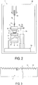
- the calculation unit 11 calculate the scratch abrasion of the rubber sample R on the basis of the detection data from the shape sensor 9a. Specifically, as illustrated in FIG. 3 , by finding the vertical variation H between a surface R1 of the previous detection and a surface R2 of the current detection and integrating the obtained values over a section in the width direction of the rubber sample R, the amount of scratch abrasion (area of the hatched portion) of the rubber sample R at the cross section for data detection can be obtained. By performing this calculation for the entire rubber sample R in the longitudinal direction, the amount of scratch abrasion for the entire rubber sample R can be calculated. Alternatively, the amount of scratch abrasion per unit length of the rubber sample R is calculated. In such a manner, the amount of scratch abrasion of the rubber sample R can be quickly determined for a certain period and a certain position (range).
- the weights of the rubber sample R before and after the rubber sample R is scratched by the contact member 4 are measured, and the amount of abrasion is obtained from the difference between the measured weights.
- the rubber sample R has to be removed from the pair of pulleys 7a, 7b.
- removing the rubber sample R requires a significant amount of man-hours.
- the amount of scratch abrasion of the rubber sample R can be determined without removing the rubber sample R from the pair of pulleys 7a.
- the workability is significantly improved.
- the pulleys 7a, 7b are rotatably supported on one side, however in other embodiments, the pulleys 7a, 7b can be rotatably supported on both sides.
- a configuration in which the pulleys 7a, 7b are supported on both sides results in the belt member B (rubber sample R) being able to run in a more stable manner. Additionally, because most pulleys of actual conveyor devices are supported on both sides, the conditions can be made even more similar to that of the actual usage environment of the conveyor belt.
- a configuration in which the pulleys 7a, 7b are supported on both sides requires a significant amount of man-hours to remove the rubber sample R from the pair of pulleys 7a, 7b as described above, however, by using the shape sensor 9a, the man-hours are reduced.
- a configuration in which the belt member B and the rubber sample R are not adhered together and can be freely separated is advantageous because the belt member B can be repeatedly used just by replacing only the used rubber sample R. Additionally, when the amount of scratch abrasion of the rubber sample R is determined, severing the rubber sample R in the belt width direction at a position partway in the longitudinal direction allows only the rubber sample R to be easily removed from the pair of pulleys 7a, 7b. Accordingly, the amount of scratch abrasion of the rubber sample R can be determined on the basis of the measured weight of the rubber sample R without using the shape sensor 9a to reduce the required amount of man-hours.
- the contact member 4 can be pressed against the surface of the rubber sample R at a position where the belt member B is supported by the support portion 17a and a position where the belt member B is not supported.
- This allows the difference in the scratch abrasion resistance (amount of abrasion, state of abrasion, and the like) of the rubber sample R at two positions to be determined. Accordingly, the scratch abrasion resistance of the upper cover rubber 14 (rubber sample R) of the conveyor belt 12 when actually used can be further accurately estimated.
- the pressing load acting on the contact member 4 (load in the vertical direction) and the load in the running direction of the rubber sample R (load in the horizontal direction) are successively detected.
- the kinetic friction coefficient of the rubber sample R can be determined on the basis of the detection data.
- the external environmental temperature of the rubber sample R can be set to a desired temperature. This allows the evaluation to be performed under conditions even more similar to that of the actual usage environment of the conveyor belt 12. Additionally, by performing evaluation differing the external environmental temperature and the temperature of the rubber sample R, the temperature dependency of the scratch abrasion resistance of the rubber sample R can be determined.
- the temperature sensor 9c By providing the temperature sensor 9c, the change in surface temperature of the rubber sample R during evaluation can be measured. When the rubber sample R is subject to abrasion, thermal energy is produced, thus the results of the temperature measurement by the temperature sensor 9c can be used to determine the energy produced when abrasion occurs. Because the amount of energy differs depending on the type of rubber used, the temperature measurement results are helpful in selecting the type of rubber that can minimize the energy produced, for example.
- the support portion 17a supporting the inner surface of the annular belt member B between the pulleys 7a, 7b can move in the running direction of the belt member B and be fixed at a discretionary position.
- the support portion 17a can be a support roller as in the present embodiment instead of a flat plate-like support portion.
- the span in which the support portion 17a can move (the support length of the belt member B which is pressed by the contact member 4) can be changed. Accordingly, by pressing the contact member 4 against the surface of the rubber sample R and performing measurement with the support portion 17a at a position so that the belt member B is not supported, the effect of the span on the scratch abrasion resistance can be determined.
- the mechanism that enables the support portion 17a to move is not particularly limited.
- the mechanism may enable movement with or without gradations.
- Examples of a mechanism that enables the support portion 17a to move include disposing rails on the base 2a to enable the support portion 17a to slide on the rail.
- the pressing mechanism which presses the contact member 4 against the surface of the rubber sample R is different than that of the previously described embodiment.
- the basic configuration is the same as that of the previously described embodiment.
- the pressing mechanism includes at least one anchor member 5 placed on the contact member 4.
- the pressing mechanism includes a base 3d to which the holding portion 3a mounted on the upper end portion of the contact member 4 is attached, a supporting column 3e disposed in an upright manner on the base 3d, and the plurality of anchor members 5 through which the supporting column 3e passes through.
- the anchor members 5 are placed on the base 3d in a layered manner.
- the base 3d is supported by another member so that it does not move out of position in the horizontal direction.
- the total weight of the base 3d, the supporting column 3e, and the anchor members 5 acts on the surface of the rubber sample R via the contact member 4. Accordingly, the pressure against the surface of the rubber sample R can be changed by changing the number of the anchor members 5 and the weight of each of the anchor members 5.
- essentially the pressing mechanism acts only as a load in the vertical direction on the contact member 4 and the rubber sample R.
- variation in the load in the horizontal direction acting on the contact member 4 and the rubber sample R can be significantly reduced. This allows for a highly accurate measurement with minimal noise, which is advantageous because the scratch abrasion resistance and the kinetic friction coefficient of the rubber sample R can be estimated with greater accuracy.
- this pressing mechanism essentially a load only in the vertical-downward direction is placed on the rubber sample R, making the rubber sample R less susceptible to movement up or down.
- up and down vibration of the rubber sample R caused by the running of the rubber sample R can be effectively suppressed.
- a highly accurate measurement with minimal noise can be performed which is advantageous because the scratch abrasion resistance and the kinetic friction coefficient of the rubber sample R can be estimated with greater accuracy.
- the pressing mechanism can also be simplified.
Landscapes
- Physics & Mathematics (AREA)
- Health & Medical Sciences (AREA)
- Life Sciences & Earth Sciences (AREA)
- Chemical & Material Sciences (AREA)
- Analytical Chemistry (AREA)
- Biochemistry (AREA)
- General Health & Medical Sciences (AREA)
- General Physics & Mathematics (AREA)
- Immunology (AREA)
- Pathology (AREA)
- Investigating Strength Of Materials By Application Of Mechanical Stress (AREA)
Claims (7)
- Dispositif de test d'abrasion aux rayures (1), comprenant :une paire de poulies (7a, 7b) ;un élément de courroie annulaire (B) tendu entre la paire de poulies (7a, 7b) ;un échantillon de caoutchouc (R) fixé à une surface externe de l'élément de courroie (B) ;un élément de contact (4) avec des pointes pointues qui peuvent venir en contact avec une surface de l'échantillon de caoutchouc (R) ;un mécanisme de pression qui presse les pointes de l'élément de contact (4) contre la surface de l'échantillon de caoutchouc (R) ; etau moins un élément d'ancrage (5) pour provoquer une charge de pression appliquée par l'élément de contact (4), la charge de pression dépendant du poids de l'au moins un élément d'ancrage (5) ;un capteur de forme (9a) configuré pour détecter une forme en coupe transversale de la surface de l'échantillon de caoutchouc (R), etune unité de calcul (11) configurée pour obtenir une quantité d'abrasion aux rayures de l'échantillon de caoutchouc (R) sur la base de données de détection provenant du capteur de forme (9a) ;une vitesse de défilement de l'échantillon de caoutchouc (R) étant variable,l'élément de contact (4) incluant une pluralité de types d'éléments de contact (4a, 4b, 4c) avec différentes spécifications de pointe ;l'élément de contact (4) qui appuie contre la surface de l'échantillon de caoutchouc (R) étant choisi de manière discrétionnaire parmi la pluralité de types d'éléments de contact (4a, 4b, 4c), etl'élément de contact choisi (4a, 4b, 4c) étant pressé contre la surface de l'échantillon de caoutchouc (R).
- Dispositif de test d'abrasion aux rayures (1) selon la revendication 1, comprenant en outre :une partie de support (17a) qui supporte une surface interne de l'élément de courroie (B) entre la paire de poulies (7a, 7b) ;l'élément de contact (4) pouvant appuyer contre la surface de l'échantillon de caoutchouc (R) au niveau d'une position où la partie de support (17a) supporte l'élément de courroie et une position où l'élément de courroie (B) n'est pas supporté.
- Dispositif de test d'abrasion aux rayures (1) selon l'une quelconque des revendications 1 à 2, comprenant en outre
un capteur de charge (9b) configuré pour détecter successivement la charge de pression agissant sur l'élément de contact (4) et une charge dans une direction de défilement de l'échantillon de caoutchouc (R) agissant sur l'élément de contact (4). - Dispositif de test d'abrasion aux rayures (1) selon l'une quelconque des revendications 1 à 3, comprenant en outre
un mécanisme de contrôle de température (10a) configuré pour faire varier une température d'environnement externe de l'échantillon de caoutchouc (R). - Dispositif de test d'abrasion à la rayure (1) selon l'une quelconque des revendications 1 à 4, comprenant en outre
un capteur de température (9c) configuré pour détecter une température de surface de l'échantillon de caoutchouc (R). - Procédé de test d'abrasion aux rayures dans lequel un élément de courroie annulaire (B) avec un échantillon de caoutchouc (R) fixé sur une surface externe de celui-ci est tendu entre une paire de poulies (7a, 7b) et un élément de contact (4) avec des pointes pointues est pressé contre une surface de l'échantillon de caoutchouc (R) par un mécanisme de pressage, le procédé de test comprenant les étapes consistant à :pour le test,régler une vitesse de défilement de l'échantillon de caoutchouc (R) sur une vitesse souhaitée ;régler une charge de pression appliquée par l'élément de contact (4) sur une charge de pression souhaitée par l'intermédiaire d'au moins un élément d'ancrage (5), la charge de pression dépendant du poids de l'au moins un élément d'ancrage (5) ;sélectionner, en tant qu'élément de contact (4), un élément de contact souhaité (4) parmi une pluralité de types d'éléments de contact (4a, 4b, 4c) avec différentes spécifications de pointe en contact avec la surface de l'échantillon de caoutchouc ;presser l'élément de contact sélectionné (4a, 4b, 4c) contre la surface de l'échantillon de caoutchouc (R) ;détecter une forme en coupe transversale de la surface de l'échantillon de caoutchouc (R) à l'aide d'un capteur de forme (9a) ; etobtenir une quantité d'abrasion aux rayures de l'échantillon de caoutchouc (R) à l'aide d'une unité de calcul (11) sur la base de données de détection provenant du capteur de forme (9a).
- Procédé de test d'abrasion aux rayures selon la revendication 6, le procédé de test comprenant en outre les étapes consistant à :supporter une surface interne de l'élément de courroie (B) avec une partie de support (17a) entre la paire de poulies (7a, 7b) ; etpresser l'élément de contact (4) contre la surface de l'échantillon de caoutchouc (R) au niveau d'une position où la partie de support (17a) supporte l'élément de courroie (B) et une position où l'élément de courroie (B) n'est pas supporté.
Applications Claiming Priority (2)
| Application Number | Priority Date | Filing Date | Title |
|---|---|---|---|
| JP2015092686A JP5991404B1 (ja) | 2015-04-30 | 2015-04-30 | 引っ掻き摩耗試験装置および方法 |
| PCT/JP2016/057531 WO2016174940A1 (fr) | 2015-04-30 | 2016-03-10 | Procédé et dispositif de test d'usure abrasive |
Publications (3)
| Publication Number | Publication Date |
|---|---|
| EP3290903A1 EP3290903A1 (fr) | 2018-03-07 |
| EP3290903A4 EP3290903A4 (fr) | 2019-01-02 |
| EP3290903B1 true EP3290903B1 (fr) | 2019-12-25 |
Family
ID=56920986
Family Applications (1)
| Application Number | Title | Priority Date | Filing Date |
|---|---|---|---|
| EP16786217.6A Active EP3290903B1 (fr) | 2015-04-30 | 2016-03-10 | Procédé et dispositif de test d'usure abrasive |
Country Status (7)
| Country | Link |
|---|---|
| US (2) | US10732084B2 (fr) |
| EP (1) | EP3290903B1 (fr) |
| JP (1) | JP5991404B1 (fr) |
| CN (2) | CN111879646A (fr) |
| AU (1) | AU2016253804B2 (fr) |
| RU (1) | RU2017134825A (fr) |
| WO (1) | WO2016174940A1 (fr) |
Families Citing this family (14)
| Publication number | Priority date | Publication date | Assignee | Title |
|---|---|---|---|---|
| CN106769586A (zh) * | 2017-02-08 | 2017-05-31 | 西华大学 | 一种农机履带磨损试验装置 |
| US10620098B2 (en) * | 2017-07-11 | 2020-04-14 | Covestro Llc | Apparatus and methods for testing components under force |
| CN109612861B (zh) * | 2018-12-06 | 2021-06-15 | 祝汪林 | 一种纺织布料耐磨性测试机 |
| CN109975148B (zh) * | 2019-01-15 | 2024-01-26 | 中信戴卡股份有限公司 | 一种自动沙粒磨损装置 |
| CN109900553B (zh) * | 2019-03-14 | 2021-08-31 | 中铁六局集团呼和浩特铁路建设有限公司 | 一种建筑混凝土抗压强度试验检测装置及其操作方法 |
| CN109975129B (zh) * | 2019-04-09 | 2022-03-22 | 安徽理工大学 | 一种可移动框架、模拟试验系统及其模拟方法 |
| CN111044398B (zh) * | 2019-11-12 | 2022-03-25 | 浙江耀阳新材料科技有限公司 | 一种薄膜防刮擦测试设备 |
| CN114313820B (zh) * | 2022-01-10 | 2022-08-23 | 江苏沃源包装制品有限公司 | 一种薄膜包装机输送速度的智能张紧装置 |
| CN114486503B (zh) * | 2022-04-18 | 2022-06-17 | 同日智能科技(徐州)有限公司 | 一种输送带制造性能检测装置及检测方法 |
| CN115372167B (zh) * | 2022-09-06 | 2025-01-28 | 临沂鲁驰新材料科技有限公司 | 橡胶输送带质量检测的检测装置及方法 |
| CN115586096B (zh) * | 2022-11-08 | 2023-06-09 | 邵东智能制造技术研究院有限公司 | 一种用于箱包抗磨度检测设备 |
| CN116429621B (zh) * | 2023-03-27 | 2023-10-24 | 嘉兴鹏翔包装材料有限公司 | 一种镀铝膜镀层耐磨性检测设备 |
| CN117169103B (zh) * | 2023-09-06 | 2024-03-08 | 中航试金石检测科技(大厂)有限公司 | 一种超高温陶瓷材料腐蚀测试设备 |
| CN117330448B (zh) * | 2023-10-26 | 2024-04-02 | 枣庄市天一实业有限公司 | 一种深海液压橡胶胶管的测试设备及工艺 |
Family Cites Families (28)
| Publication number | Priority date | Publication date | Assignee | Title |
|---|---|---|---|---|
| JP3076360B2 (ja) * | 1990-08-21 | 2000-08-14 | 株式会社ブリヂストン | コード入りゴムシートの切断不良検出方法 |
| JPH08189885A (ja) * | 1995-01-09 | 1996-07-23 | Toray Ind Inc | 防護資材の耐切創性試験装置 |
| US5900531A (en) * | 1997-04-07 | 1999-05-04 | Bridgestone/Firestone, Inc. | Portable universal friction testing machine and method |
| US6321586B1 (en) * | 1999-02-01 | 2001-11-27 | Lockheed Martin Federal Systems, Inc. | Conveyor friction measurement and cleaning system |
| JP2001088922A (ja) | 1999-09-20 | 2001-04-03 | Bando Chem Ind Ltd | 耐摩耗性コンベヤベルト |
| KR100368559B1 (ko) * | 2000-06-29 | 2003-01-24 | 한국타이어 주식회사 | 고무시편의 마모시험장치 |
| US20050050942A1 (en) * | 2001-09-07 | 2005-03-10 | Schmitt Edward A. | Wear test system |
| JP2004020319A (ja) * | 2002-06-14 | 2004-01-22 | Jfe Steel Kk | コンベヤベルトの摩耗試験装置 |
| JP4343791B2 (ja) * | 2004-07-26 | 2009-10-14 | 株式会社ブリヂストン | 加硫ゴムの摩耗試験方法 |
| CN200989873Y (zh) | 2006-09-05 | 2007-12-12 | 上海市机械施工有限公司 | 地下掘削类硬质合金磨耗试验装置 |
| CN201004038Y (zh) | 2007-02-05 | 2008-01-09 | 华南理工大学 | 一种橡胶磨耗测试设备 |
| JP2010260645A (ja) * | 2007-08-31 | 2010-11-18 | Bridgestone Corp | コンベヤベルトの摩耗状態検出装置 |
| CN101556238B (zh) * | 2009-05-11 | 2011-11-16 | 中国船舶重工集团公司第七二五研究所 | 一种直线往复式滑动摩擦磨损测试装置及方法 |
| CN101725025B (zh) * | 2009-11-20 | 2011-07-20 | 东华大学 | 一种动态拉伸条件下纺织浆膜磨损试验装置及方法 |
| JP5534588B2 (ja) | 2010-02-24 | 2014-07-02 | 株式会社ブリヂストン | タイヤのゴムインデックス算出方法、装置及びプログラム |
| JP5327132B2 (ja) * | 2010-04-27 | 2013-10-30 | 三菱電機株式会社 | 摩耗試験装置及び摩耗試験方法 |
| JP5486412B2 (ja) * | 2010-06-07 | 2014-05-07 | 横浜ゴム株式会社 | コンベヤベルトの耐衝撃性の評価システムおよび評価方法 |
| CN102004060B (zh) * | 2010-09-10 | 2013-06-12 | 杭州中策橡胶有限公司 | 一种测量橡胶材料抗尖锐物刺扎性能的试验方法和装置 |
| JP2012202811A (ja) * | 2011-03-25 | 2012-10-22 | Meiji Rubber & Chem Co Ltd | ゴム材料等の摩耗試験方法及びこれに用いる摩耗試験装置 |
| JP2012202926A (ja) * | 2011-03-28 | 2012-10-22 | Bridgestone Corp | 摩耗試験装置 |
| JP5834486B2 (ja) * | 2011-05-18 | 2015-12-24 | 横浜ゴム株式会社 | コンベヤベルトの評価装置および評価方法 |
| CN102854075B (zh) * | 2011-06-28 | 2016-03-09 | 东莞劲胜精密组件股份有限公司 | 一种涂层耐人工爪磨耗性能的测试方法 |
| CN102384881B (zh) * | 2011-11-24 | 2013-02-13 | 成都市新筑路桥机械股份有限公司 | 一种橡胶履带板磨耗性能的测试装置及方法 |
| CN202362219U (zh) * | 2011-11-24 | 2012-08-01 | 成都市新筑路桥机械股份有限公司 | 一种橡胶履带板磨耗性能的测试装置 |
| CN202433272U (zh) * | 2011-12-27 | 2012-09-12 | 江门市本和机车配件实业有限公司 | 金属橡胶复合密封板高温表面摩擦磨损试验仪 |
| JP6002462B2 (ja) * | 2012-06-15 | 2016-10-05 | 横浜ゴム株式会社 | コンベヤベルトの支持ローラ乗り越え抵抗力測定方法およびその装置 |
| JP5915456B2 (ja) * | 2012-08-23 | 2016-05-11 | 横浜ゴム株式会社 | コンベヤベルト |
| CN104502215B (zh) * | 2015-01-08 | 2017-05-24 | 攀钢集团研究院有限公司 | 磨损试验装置及试验方法 |
-
2015
- 2015-04-30 JP JP2015092686A patent/JP5991404B1/ja active Active
-
2016
- 2016-03-10 AU AU2016253804A patent/AU2016253804B2/en not_active Ceased
- 2016-03-10 US US15/570,709 patent/US10732084B2/en not_active Expired - Fee Related
- 2016-03-10 EP EP16786217.6A patent/EP3290903B1/fr active Active
- 2016-03-10 WO PCT/JP2016/057531 patent/WO2016174940A1/fr not_active Ceased
- 2016-03-10 CN CN202010860710.7A patent/CN111879646A/zh active Pending
- 2016-03-10 CN CN201680019732.2A patent/CN107532982B/zh active Active
- 2016-03-10 RU RU2017134825A patent/RU2017134825A/ru not_active Application Discontinuation
-
2020
- 2020-07-02 US US16/920,354 patent/US11231353B2/en active Active
Non-Patent Citations (1)
| Title |
|---|
| None * |
Also Published As
| Publication number | Publication date |
|---|---|
| JP5991404B1 (ja) | 2016-09-14 |
| CN107532982A (zh) | 2018-01-02 |
| EP3290903A4 (fr) | 2019-01-02 |
| AU2016253804B2 (en) | 2018-09-13 |
| CN107532982B (zh) | 2020-09-22 |
| WO2016174940A1 (fr) | 2016-11-03 |
| US20200333227A1 (en) | 2020-10-22 |
| CN111879646A (zh) | 2020-11-03 |
| US11231353B2 (en) | 2022-01-25 |
| RU2017134825A3 (fr) | 2019-04-04 |
| US10732084B2 (en) | 2020-08-04 |
| EP3290903A1 (fr) | 2018-03-07 |
| RU2017134825A (ru) | 2019-04-04 |
| AU2016253804A1 (en) | 2017-10-19 |
| US20180292301A1 (en) | 2018-10-11 |
| JP2016211869A (ja) | 2016-12-15 |
Similar Documents
| Publication | Publication Date | Title |
|---|---|---|
| EP3290903B1 (fr) | Procédé et dispositif de test d'usure abrasive | |
| US10371613B2 (en) | Apparatus and method for loading and wear testing a rubber sample | |
| JP6394295B2 (ja) | 摩耗試験装置および方法 | |
| US10184857B2 (en) | Impact test device and method | |
| US10928284B2 (en) | Impact test method and device in which an impact application member is caused to fall freely onto and collide with a test sample | |
| AU2017296469B2 (en) | Method for evaluating wear resistance of rubber | |
| AU2013275272B2 (en) | Method for measuring resistance of conveyor belt to getting over support roller, and device therefor | |
| KR101892399B1 (ko) | 복열 어레이 센서를 갖는 콘크리트 화재손상 깊이 측정 장치 | |
| US20190003946A1 (en) | Testing and/or Inspection Device | |
| JP2006292736A (ja) | コンベヤベルトのコンベヤローラ乗り越え抵抗力測定方法およびその装置並びにコンベヤベルトの動力損失の評価方法 | |
| AU2017296468B2 (en) | Rubber wear testing device | |
| WO2012132226A1 (fr) | Appareil d'essais d'usure | |
| JP6503694B2 (ja) | 衝撃試験装置および方法 | |
| KR102360876B1 (ko) | 타이어 성능 평가용 실내 시험 장치 |
Legal Events
| Date | Code | Title | Description |
|---|---|---|---|
| STAA | Information on the status of an ep patent application or granted ep patent |
Free format text: STATUS: THE INTERNATIONAL PUBLICATION HAS BEEN MADE |
|
| PUAI | Public reference made under article 153(3) epc to a published international application that has entered the european phase |
Free format text: ORIGINAL CODE: 0009012 |
|
| STAA | Information on the status of an ep patent application or granted ep patent |
Free format text: STATUS: REQUEST FOR EXAMINATION WAS MADE |
|
| 17P | Request for examination filed |
Effective date: 20171017 |
|
| AK | Designated contracting states |
Kind code of ref document: A1 Designated state(s): AL AT BE BG CH CY CZ DE DK EE ES FI FR GB GR HR HU IE IS IT LI LT LU LV MC MK MT NL NO PL PT RO RS SE SI SK SM TR |
|
| AX | Request for extension of the european patent |
Extension state: BA ME |
|
| DAV | Request for validation of the european patent (deleted) | ||
| DAX | Request for extension of the european patent (deleted) | ||
| STAA | Information on the status of an ep patent application or granted ep patent |
Free format text: STATUS: EXAMINATION IS IN PROGRESS |
|
| A4 | Supplementary search report drawn up and despatched |
Effective date: 20181129 |
|
| RIC1 | Information provided on ipc code assigned before grant |
Ipc: G01N 3/56 20060101AFI20181123BHEP |
|
| 17Q | First examination report despatched |
Effective date: 20181210 |
|
| GRAP | Despatch of communication of intention to grant a patent |
Free format text: ORIGINAL CODE: EPIDOSNIGR1 |
|
| STAA | Information on the status of an ep patent application or granted ep patent |
Free format text: STATUS: GRANT OF PATENT IS INTENDED |
|
| INTG | Intention to grant announced |
Effective date: 20190723 |
|
| GRAS | Grant fee paid |
Free format text: ORIGINAL CODE: EPIDOSNIGR3 |
|
| GRAA | (expected) grant |
Free format text: ORIGINAL CODE: 0009210 |
|
| STAA | Information on the status of an ep patent application or granted ep patent |
Free format text: STATUS: THE PATENT HAS BEEN GRANTED |
|
| AK | Designated contracting states |
Kind code of ref document: B1 Designated state(s): AL AT BE BG CH CY CZ DE DK EE ES FI FR GB GR HR HU IE IS IT LI LT LU LV MC MK MT NL NO PL PT RO RS SE SI SK SM TR |
|
| REG | Reference to a national code |
Ref country code: GB Ref legal event code: FG4D |
|
| REG | Reference to a national code |
Ref country code: CH Ref legal event code: EP |
|
| REG | Reference to a national code |
Ref country code: AT Ref legal event code: REF Ref document number: 1217652 Country of ref document: AT Kind code of ref document: T Effective date: 20200115 |
|
| REG | Reference to a national code |
Ref country code: DE Ref legal event code: R096 Ref document number: 602016026962 Country of ref document: DE |
|
| REG | Reference to a national code |
Ref country code: IE Ref legal event code: FG4D |
|
| REG | Reference to a national code |
Ref country code: NL Ref legal event code: MP Effective date: 20191225 |
|
| PG25 | Lapsed in a contracting state [announced via postgrant information from national office to epo] |
Ref country code: BG Free format text: LAPSE BECAUSE OF FAILURE TO SUBMIT A TRANSLATION OF THE DESCRIPTION OR TO PAY THE FEE WITHIN THE PRESCRIBED TIME-LIMIT Effective date: 20200325 Ref country code: GR Free format text: LAPSE BECAUSE OF FAILURE TO SUBMIT A TRANSLATION OF THE DESCRIPTION OR TO PAY THE FEE WITHIN THE PRESCRIBED TIME-LIMIT Effective date: 20200326 Ref country code: NO Free format text: LAPSE BECAUSE OF FAILURE TO SUBMIT A TRANSLATION OF THE DESCRIPTION OR TO PAY THE FEE WITHIN THE PRESCRIBED TIME-LIMIT Effective date: 20200325 Ref country code: FI Free format text: LAPSE BECAUSE OF FAILURE TO SUBMIT A TRANSLATION OF THE DESCRIPTION OR TO PAY THE FEE WITHIN THE PRESCRIBED TIME-LIMIT Effective date: 20191225 Ref country code: LT Free format text: LAPSE BECAUSE OF FAILURE TO SUBMIT A TRANSLATION OF THE DESCRIPTION OR TO PAY THE FEE WITHIN THE PRESCRIBED TIME-LIMIT Effective date: 20191225 Ref country code: SE Free format text: LAPSE BECAUSE OF FAILURE TO SUBMIT A TRANSLATION OF THE DESCRIPTION OR TO PAY THE FEE WITHIN THE PRESCRIBED TIME-LIMIT Effective date: 20191225 Ref country code: LV Free format text: LAPSE BECAUSE OF FAILURE TO SUBMIT A TRANSLATION OF THE DESCRIPTION OR TO PAY THE FEE WITHIN THE PRESCRIBED TIME-LIMIT Effective date: 20191225 |
|
| REG | Reference to a national code |
Ref country code: LT Ref legal event code: MG4D |
|
| PG25 | Lapsed in a contracting state [announced via postgrant information from national office to epo] |
Ref country code: RS Free format text: LAPSE BECAUSE OF FAILURE TO SUBMIT A TRANSLATION OF THE DESCRIPTION OR TO PAY THE FEE WITHIN THE PRESCRIBED TIME-LIMIT Effective date: 20191225 Ref country code: HR Free format text: LAPSE BECAUSE OF FAILURE TO SUBMIT A TRANSLATION OF THE DESCRIPTION OR TO PAY THE FEE WITHIN THE PRESCRIBED TIME-LIMIT Effective date: 20191225 |
|
| PG25 | Lapsed in a contracting state [announced via postgrant information from national office to epo] |
Ref country code: AL Free format text: LAPSE BECAUSE OF FAILURE TO SUBMIT A TRANSLATION OF THE DESCRIPTION OR TO PAY THE FEE WITHIN THE PRESCRIBED TIME-LIMIT Effective date: 20191225 |
|
| PG25 | Lapsed in a contracting state [announced via postgrant information from national office to epo] |
Ref country code: EE Free format text: LAPSE BECAUSE OF FAILURE TO SUBMIT A TRANSLATION OF THE DESCRIPTION OR TO PAY THE FEE WITHIN THE PRESCRIBED TIME-LIMIT Effective date: 20191225 Ref country code: NL Free format text: LAPSE BECAUSE OF FAILURE TO SUBMIT A TRANSLATION OF THE DESCRIPTION OR TO PAY THE FEE WITHIN THE PRESCRIBED TIME-LIMIT Effective date: 20191225 Ref country code: RO Free format text: LAPSE BECAUSE OF FAILURE TO SUBMIT A TRANSLATION OF THE DESCRIPTION OR TO PAY THE FEE WITHIN THE PRESCRIBED TIME-LIMIT Effective date: 20191225 Ref country code: CZ Free format text: LAPSE BECAUSE OF FAILURE TO SUBMIT A TRANSLATION OF THE DESCRIPTION OR TO PAY THE FEE WITHIN THE PRESCRIBED TIME-LIMIT Effective date: 20191225 Ref country code: PT Free format text: LAPSE BECAUSE OF FAILURE TO SUBMIT A TRANSLATION OF THE DESCRIPTION OR TO PAY THE FEE WITHIN THE PRESCRIBED TIME-LIMIT Effective date: 20200520 |
|
| PG25 | Lapsed in a contracting state [announced via postgrant information from national office to epo] |
Ref country code: SK Free format text: LAPSE BECAUSE OF FAILURE TO SUBMIT A TRANSLATION OF THE DESCRIPTION OR TO PAY THE FEE WITHIN THE PRESCRIBED TIME-LIMIT Effective date: 20191225 Ref country code: IS Free format text: LAPSE BECAUSE OF FAILURE TO SUBMIT A TRANSLATION OF THE DESCRIPTION OR TO PAY THE FEE WITHIN THE PRESCRIBED TIME-LIMIT Effective date: 20200425 Ref country code: SM Free format text: LAPSE BECAUSE OF FAILURE TO SUBMIT A TRANSLATION OF THE DESCRIPTION OR TO PAY THE FEE WITHIN THE PRESCRIBED TIME-LIMIT Effective date: 20191225 |
|
| REG | Reference to a national code |
Ref country code: DE Ref legal event code: R097 Ref document number: 602016026962 Country of ref document: DE |
|
| PG25 | Lapsed in a contracting state [announced via postgrant information from national office to epo] |
Ref country code: DK Free format text: LAPSE BECAUSE OF FAILURE TO SUBMIT A TRANSLATION OF THE DESCRIPTION OR TO PAY THE FEE WITHIN THE PRESCRIBED TIME-LIMIT Effective date: 20191225 Ref country code: MC Free format text: LAPSE BECAUSE OF FAILURE TO SUBMIT A TRANSLATION OF THE DESCRIPTION OR TO PAY THE FEE WITHIN THE PRESCRIBED TIME-LIMIT Effective date: 20191225 Ref country code: ES Free format text: LAPSE BECAUSE OF FAILURE TO SUBMIT A TRANSLATION OF THE DESCRIPTION OR TO PAY THE FEE WITHIN THE PRESCRIBED TIME-LIMIT Effective date: 20191225 |
|
| PLBE | No opposition filed within time limit |
Free format text: ORIGINAL CODE: 0009261 |
|
| REG | Reference to a national code |
Ref country code: CH Ref legal event code: PL |
|
| STAA | Information on the status of an ep patent application or granted ep patent |
Free format text: STATUS: NO OPPOSITION FILED WITHIN TIME LIMIT |
|
| REG | Reference to a national code |
Ref country code: AT Ref legal event code: MK05 Ref document number: 1217652 Country of ref document: AT Kind code of ref document: T Effective date: 20191225 |
|
| PG25 | Lapsed in a contracting state [announced via postgrant information from national office to epo] |
Ref country code: SI Free format text: LAPSE BECAUSE OF FAILURE TO SUBMIT A TRANSLATION OF THE DESCRIPTION OR TO PAY THE FEE WITHIN THE PRESCRIBED TIME-LIMIT Effective date: 20191225 |
|
| 26N | No opposition filed |
Effective date: 20200928 |
|
| REG | Reference to a national code |
Ref country code: BE Ref legal event code: MM Effective date: 20200331 |
|
| PG25 | Lapsed in a contracting state [announced via postgrant information from national office to epo] |
Ref country code: LU Free format text: LAPSE BECAUSE OF NON-PAYMENT OF DUE FEES Effective date: 20200310 |
|
| PG25 | Lapsed in a contracting state [announced via postgrant information from national office to epo] |
Ref country code: LI Free format text: LAPSE BECAUSE OF NON-PAYMENT OF DUE FEES Effective date: 20200331 Ref country code: FR Free format text: LAPSE BECAUSE OF NON-PAYMENT OF DUE FEES Effective date: 20200331 Ref country code: IE Free format text: LAPSE BECAUSE OF NON-PAYMENT OF DUE FEES Effective date: 20200310 Ref country code: IT Free format text: LAPSE BECAUSE OF FAILURE TO SUBMIT A TRANSLATION OF THE DESCRIPTION OR TO PAY THE FEE WITHIN THE PRESCRIBED TIME-LIMIT Effective date: 20191225 Ref country code: CH Free format text: LAPSE BECAUSE OF NON-PAYMENT OF DUE FEES Effective date: 20200331 Ref country code: AT Free format text: LAPSE BECAUSE OF FAILURE TO SUBMIT A TRANSLATION OF THE DESCRIPTION OR TO PAY THE FEE WITHIN THE PRESCRIBED TIME-LIMIT Effective date: 20191225 |
|
| PG25 | Lapsed in a contracting state [announced via postgrant information from national office to epo] |
Ref country code: BE Free format text: LAPSE BECAUSE OF NON-PAYMENT OF DUE FEES Effective date: 20200331 Ref country code: PL Free format text: LAPSE BECAUSE OF FAILURE TO SUBMIT A TRANSLATION OF THE DESCRIPTION OR TO PAY THE FEE WITHIN THE PRESCRIBED TIME-LIMIT Effective date: 20191225 |
|
| GBPC | Gb: european patent ceased through non-payment of renewal fee |
Effective date: 20200325 |
|
| PG25 | Lapsed in a contracting state [announced via postgrant information from national office to epo] |
Ref country code: GB Free format text: LAPSE BECAUSE OF NON-PAYMENT OF DUE FEES Effective date: 20200325 |
|
| PG25 | Lapsed in a contracting state [announced via postgrant information from national office to epo] |
Ref country code: TR Free format text: LAPSE BECAUSE OF FAILURE TO SUBMIT A TRANSLATION OF THE DESCRIPTION OR TO PAY THE FEE WITHIN THE PRESCRIBED TIME-LIMIT Effective date: 20191225 Ref country code: MT Free format text: LAPSE BECAUSE OF FAILURE TO SUBMIT A TRANSLATION OF THE DESCRIPTION OR TO PAY THE FEE WITHIN THE PRESCRIBED TIME-LIMIT Effective date: 20191225 Ref country code: CY Free format text: LAPSE BECAUSE OF FAILURE TO SUBMIT A TRANSLATION OF THE DESCRIPTION OR TO PAY THE FEE WITHIN THE PRESCRIBED TIME-LIMIT Effective date: 20191225 |
|
| PG25 | Lapsed in a contracting state [announced via postgrant information from national office to epo] |
Ref country code: MK Free format text: LAPSE BECAUSE OF FAILURE TO SUBMIT A TRANSLATION OF THE DESCRIPTION OR TO PAY THE FEE WITHIN THE PRESCRIBED TIME-LIMIT Effective date: 20191225 |
|
| P01 | Opt-out of the competence of the unified patent court (upc) registered |
Effective date: 20230512 |
|
| PGFP | Annual fee paid to national office [announced via postgrant information from national office to epo] |
Ref country code: DE Payment date: 20260128 Year of fee payment: 11 |