EP3290931B1 - Capteur de tension interférométrique avec compensation d'erreur - Google Patents
Capteur de tension interférométrique avec compensation d'erreur Download PDFInfo
- Publication number
- EP3290931B1 EP3290931B1 EP16187127.2A EP16187127A EP3290931B1 EP 3290931 B1 EP3290931 B1 EP 3290931B1 EP 16187127 A EP16187127 A EP 16187127A EP 3290931 B1 EP3290931 B1 EP 3290931B1
- Authority
- EP
- European Patent Office
- Prior art keywords
- voltage
- electro
- optic element
- faraday rotator
- calibration
- Prior art date
- Legal status (The legal status is an assumption and is not a legal conclusion. Google has not performed a legal analysis and makes no representation as to the accuracy of the status listed.)
- Not-in-force
Links
Images


Classifications
-
- G—PHYSICS
- G01—MEASURING; TESTING
- G01R—MEASURING ELECTRIC VARIABLES; MEASURING MAGNETIC VARIABLES
- G01R15/00—Details of measuring arrangements of the types provided for in groups G01R17/00 - G01R29/00, G01R33/00 - G01R33/26 or G01R35/00
- G01R15/14—Adaptations providing voltage or current isolation, e.g. for high-voltage or high-current networks
- G01R15/24—Adaptations providing voltage or current isolation, e.g. for high-voltage or high-current networks using light-modulating devices
- G01R15/241—Adaptations providing voltage or current isolation, e.g. for high-voltage or high-current networks using light-modulating devices using electro-optical modulators, e.g. electro-absorption
-
- G—PHYSICS
- G01—MEASURING; TESTING
- G01R—MEASURING ELECTRIC VARIABLES; MEASURING MAGNETIC VARIABLES
- G01R15/00—Details of measuring arrangements of the types provided for in groups G01R17/00 - G01R29/00, G01R33/00 - G01R33/26 or G01R35/00
- G01R15/14—Adaptations providing voltage or current isolation, e.g. for high-voltage or high-current networks
- G01R15/24—Adaptations providing voltage or current isolation, e.g. for high-voltage or high-current networks using light-modulating devices
- G01R15/241—Adaptations providing voltage or current isolation, e.g. for high-voltage or high-current networks using light-modulating devices using electro-optical modulators, e.g. electro-absorption
- G01R15/242—Adaptations providing voltage or current isolation, e.g. for high-voltage or high-current networks using light-modulating devices using electro-optical modulators, e.g. electro-absorption based on the Pockels effect, i.e. linear electro-optic effect
-
- G—PHYSICS
- G01—MEASURING; TESTING
- G01R—MEASURING ELECTRIC VARIABLES; MEASURING MAGNETIC VARIABLES
- G01R15/00—Details of measuring arrangements of the types provided for in groups G01R17/00 - G01R29/00, G01R33/00 - G01R33/26 or G01R35/00
- G01R15/14—Adaptations providing voltage or current isolation, e.g. for high-voltage or high-current networks
- G01R15/24—Adaptations providing voltage or current isolation, e.g. for high-voltage or high-current networks using light-modulating devices
- G01R15/245—Adaptations providing voltage or current isolation, e.g. for high-voltage or high-current networks using light-modulating devices using magneto-optical modulators, e.g. based on the Faraday or Cotton-Mouton effect
-
- G—PHYSICS
- G01—MEASURING; TESTING
- G01R—MEASURING ELECTRIC VARIABLES; MEASURING MAGNETIC VARIABLES
- G01R15/00—Details of measuring arrangements of the types provided for in groups G01R17/00 - G01R29/00, G01R33/00 - G01R33/26 or G01R35/00
- G01R15/14—Adaptations providing voltage or current isolation, e.g. for high-voltage or high-current networks
- G01R15/24—Adaptations providing voltage or current isolation, e.g. for high-voltage or high-current networks using light-modulating devices
- G01R15/245—Adaptations providing voltage or current isolation, e.g. for high-voltage or high-current networks using light-modulating devices using magneto-optical modulators, e.g. based on the Faraday or Cotton-Mouton effect
- G01R15/246—Adaptations providing voltage or current isolation, e.g. for high-voltage or high-current networks using light-modulating devices using magneto-optical modulators, e.g. based on the Faraday or Cotton-Mouton effect based on the Faraday, i.e. linear magneto-optic, effect
-
- G—PHYSICS
- G01—MEASURING; TESTING
- G01R—MEASURING ELECTRIC VARIABLES; MEASURING MAGNETIC VARIABLES
- G01R19/00—Arrangements for measuring currents or voltages or for indicating presence or sign thereof
- G01R19/0084—Measuring voltage only
-
- G—PHYSICS
- G01—MEASURING; TESTING
- G01R—MEASURING ELECTRIC VARIABLES; MEASURING MAGNETIC VARIABLES
- G01R35/00—Testing or calibrating of apparatus covered by the other groups of this subclass
- G01R35/005—Calibrating; Standards or reference devices, e.g. voltage or resistance standards, "golden" references
-
- G—PHYSICS
- G01—MEASURING; TESTING
- G01C—MEASURING DISTANCES, LEVELS OR BEARINGS; SURVEYING; NAVIGATION; GYROSCOPIC INSTRUMENTS; PHOTOGRAMMETRY OR VIDEOGRAMMETRY
- G01C19/00—Gyroscopes; Turn-sensitive devices using vibrating masses; Turn-sensitive devices without moving masses; Measuring angular rate using gyroscopic effects
- G01C19/58—Turn-sensitive devices without moving masses
- G01C19/64—Gyrometers using the Sagnac effect, i.e. rotation-induced shifts between counter-rotating electromagnetic beams
- G01C19/72—Gyrometers using the Sagnac effect, i.e. rotation-induced shifts between counter-rotating electromagnetic beams with counter-rotating light beams in a passive ring, e.g. fibre laser gyrometers
-
- G—PHYSICS
- G01—MEASURING; TESTING
- G01R—MEASURING ELECTRIC VARIABLES; MEASURING MAGNETIC VARIABLES
- G01R15/00—Details of measuring arrangements of the types provided for in groups G01R17/00 - G01R29/00, G01R33/00 - G01R33/26 or G01R35/00
- G01R15/14—Adaptations providing voltage or current isolation, e.g. for high-voltage or high-current networks
- G01R15/24—Adaptations providing voltage or current isolation, e.g. for high-voltage or high-current networks using light-modulating devices
- G01R15/247—Details of the circuitry or construction of devices covered by G01R15/241 - G01R15/246
-
- G—PHYSICS
- G01—MEASURING; TESTING
- G01R—MEASURING ELECTRIC VARIABLES; MEASURING MAGNETIC VARIABLES
- G01R33/00—Arrangements or instruments for measuring magnetic variables
- G01R33/02—Measuring direction or magnitude of magnetic fields or magnetic flux
- G01R33/032—Measuring direction or magnitude of magnetic fields or magnetic flux using magneto-optic devices, e.g. Faraday or Cotton-Mouton effect
- G01R33/0322—Measuring direction or magnitude of magnetic fields or magnetic flux using magneto-optic devices, e.g. Faraday or Cotton-Mouton effect using the Faraday or Voigt effect
-
- G—PHYSICS
- G02—OPTICS
- G02F—OPTICAL DEVICES OR ARRANGEMENTS FOR THE CONTROL OF LIGHT BY MODIFICATION OF THE OPTICAL PROPERTIES OF THE MEDIA OF THE ELEMENTS INVOLVED THEREIN; NON-LINEAR OPTICS; FREQUENCY-CHANGING OF LIGHT; OPTICAL LOGIC ELEMENTS; OPTICAL ANALOGUE/DIGITAL CONVERTERS
- G02F1/00—Devices or arrangements for the control of the intensity, colour, phase, polarisation or direction of light arriving from an independent light source, e.g. switching, gating or modulating; Non-linear optics
- G02F1/01—Devices or arrangements for the control of the intensity, colour, phase, polarisation or direction of light arriving from an independent light source, e.g. switching, gating or modulating; Non-linear optics for the control of the intensity, phase, polarisation or colour
- G02F1/0136—Devices or arrangements for the control of the intensity, colour, phase, polarisation or direction of light arriving from an independent light source, e.g. switching, gating or modulating; Non-linear optics for the control of the intensity, phase, polarisation or colour for the control of polarisation, e.g. state of polarisation [SOP] control, polarisation scrambling, TE-TM mode conversion or separation
Definitions
- This invention pertains to the systematic error compensation scheme used in an optical voltage sensor. It relates to a method and a device for measuring voltages.
- the advantages of the reflective modulation phase detection (MPD) measurement scheme [2] are, in particular, the excellent stability of its scale factor and zero point, both of which are needed for the accurate measurement of a DC voltage.
- MPD reflective modulation phase detection
- the concept uses a 45° Faraday rotator inserted between the polarization-maintaining (PM) fiber and the electro-optic crystal in the voltage sensor.
- An interference-contrast-based period disambiguation method has been developed to enable the extension of the unambiguous voltage measurement range to ⁇ 500 kV [1].
- Modulation phase detection [2] is a powerful interrogation technique to measure phase shift in an optical system.
- MPD sensors can e.g. be implemented in a reciprocal configuration, either in the form of a Sagnac interferometer or in a reflective form, in order to cancel phase shifts from additional birefringent elements in the system (such as PM fibers or the phase modulator crystal), which may drift slowly, e.g. with temperature change or mechanical disturbance.
- the MPD detection scheme can also be used for optical voltage sensing.
- a suitable device is shown in Fig. 1 . It comprises an MPD optoelectronics module 1 for generating waves along both polarization directions of a polarization maintaining (PM) fiber 2.
- a collimator 3 sends these waves through a 45° Faraday rotator 4 and into a first end of Pockels effect crystal 5, which is being exposed to the electrical field from the voltage to be measured.
- the waves are reflected by a reflector 6 and sent back through the components 1 - 5 and into MPD optoelectronics module 1.
- Faraday rotator 4 rotates both linear polarizations from PM fiber 2 by 45° before they propagate along the electro-optic axes of sensing crystal 5 [3].
- the reflected waves pass through Faraday rotator 4 again, further rotating the polarizations by 45° in the same direction, thereby making a combined 90° rotation from the input polarizations, which is equivalent to a swap between the two orthogonal linear polarizations.
- the two returning polarizations are brought to interference in MPD optoelectronics module 1, which gives rise to a signal with a basically periodic dependence of the voltage to be measured.
- the voltage range exceeds the ⁇ -voltage of the sensing crystal (e.g. 75 kV for BGO), it is necessary to resolve the phase shift period ambiguity in order to uniquely determine the applied voltage. This is particularly critical for DC measurements, where history tracking methods such as zero-crossing counting are not applicable.
- the interference contrast of a low-coherence light source can be used to determine the phase shift period [1]. It can be shown that for both an open-loop sinusoidal-modulation and a closed-loop square-wave modulation MPD system, it is possible to measure the interference contrast in addition to the phase shift principal value, and to combine them to determine a unique voltage value.
- Faraday rotator 4 has a perfect 45° rotation angle, and the PM fiber axes are aligned exactly at 45° with respect to the electro-optic axes of sensing crystal 5.
- deviations in the Faraday rotation angle and angular alignment are difficult to avoid, and the Faraday rotation angle is also strongly dependent on wavelength and temperature. These systematic errors can cause the measurement result to deviate significantly from theoretical expectations.
- the problem to be solved is to provide a method and device of this type with a large measurement range that are less sensitive to misalignments and/or variations of the rotation in the Faraday rotator.
- the method comprises the steps of:
- the invention also relates to a device for measuring a voltage.
- the device comprises a Faraday rotator, an electro-optic element, a reflector, a light source positioned to send light through said Faraday rotator and said electro-optic element onto the reflector and from there back through said electro-optic element and said Faraday rotator, wherein two polarizations of said light (namely those polarized along the principal refractive index axes of the electro-optic element) suffer a voltage-dependent phase shift in said electro-optic element, a light detector positioned to measure an interference between said two polarizations returning from that electro-optic element and said Faraday rotator, and a control unit adapted and structured to carry at the steps described above.
- the method can further comprise calibration steps. These calibration steps comprise:
- the contrast and principal value are measured for a plurality of voltage values of the reference voltage. Using the measured values of the contrast and principal value at the several voltage values, one or more of the calibration values can then be calculated.
- the varying electrical field is varied over a range sufficient to generate phase shifts between said polarizations that vary by at least ⁇ , in particular by at least 2 ⁇ .
- the uncompensated complex value K is substantially periodic in the phase shift between the polarizations and describes a spiral in the complex plane.
- the center as well as the real and imaginary axis amplitudes of this spiral basically describe the calibration values.
- the complex argument of K substantially corresponds to the phase shift between the polarization.
- the center and axis amplitudes of the spiral can best be determined by varying the phase shift by at least ⁇ , in particular by at least 2 ⁇ .
- the calibration steps advantageously comprise the step of determining a center and real and imaginary scaling factors of a spiral connecting said uncompensated complex value K when varying said principal value ⁇ .
- the invention is based on the idea that a refined model and scheme are needed to account for and compensate errors caused by misalignment of the components and non-45° rotations in the Faraday rotator.
- the invention is particularly suited to measure high voltages of at least 100 kV, in particular of at least 500 kV. It can advantageously be used for DC voltages. But it can also be used for measuring AC voltages, in which case the rising of falling slope of the voltage can be used to determine the corrected values k ⁇ and ⁇ .
- the technique can provide high accuracy, with errors ⁇ 0.2%.
- the sensor and method are e.g. ideal for various HVDC applications, including HVDC Light, HVDC Classic, and HVDC for offshore DC applications, e.g. in a DC GIS. Accordingly, the invention also relates to the use of the device or method for measuring a DC voltage of at least 100 kV.
- MPD optoelectronics module 1 for generating waves along both polarization directions of a polarization maintaining (PM) fiber 2.
- a collimator 3 sends these waves through a 45° Faraday rotator 4 and into a first end of Pockels effect crystal 5, which is being exposed to the electrical field from the voltage to be measured.
- the waves are reflected by a reflector 6 and sent back through the components 1 - 5 and into MPD optoelectronics module 1.
- Faraday rotator 4 rotates both linear polarizations from PM fiber 2 by 45° before they propagate along the electro-optic axes (principal refractive index axes) of sensing crystal 5 [3].
- the reflected waves pass through Faraday rotator 4 again, further rotating the polarizations by 45° in the same direction, thereby making a combined 90° rotation from the input polarizations, which is equivalent to a swap between the two orthogonal linear polarizations.
- the optoelectronics module 1 comprises a phase modulator 7 adapted to introduce a phase shift ⁇ m between the two light polarizations returning in PM fiber 2 before they are brought to interference in a detector 8.
- the coherence length of light source 9 is advantageously between 5 ⁇ ⁇ 0 and 100 ⁇ ⁇ 0 , with ⁇ 0 being the center wavelength of the light source, in order to obtain a good variation of interference contrast k when changing the phase between the two polarizations by a few multiples of 2 ⁇ .
- the device further comprises a control unit 10 adapted and structured to carry out the measurement and error compensation methods described below. It can e.g. be formed by a microprocessor or microcontroller provided with suitable interface circuits.
- the interference contrast k and principal value ⁇ can e.g. be determined e.g. as described in [1].
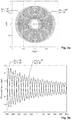
- the trace of a complex output with its absolute value equal to the MPD-measured interference contrast k and its argument equal to the MPD-measured phase shift principal value ⁇ is a spiral curve in the complex plane.
- the influence of systematic errors in a reflective optical voltage sensor, such as Faraday rotation angle error and axis alignment error, can be represented as a shift of the spiral center from the complex plane origin, and scaling of the spiral radii along the real and imaginary axes.
- the systematic measurement error can then be compensated by recentering and rescaling the measured spiral trace, yielding a more accurate phase shift measurement.
- the double-pass electro-optic phase shift ⁇ is proportional to the applied voltage V , which we aim to recover from the measurement.
- the component matrices represent a 45° Faraday rotation, a -45° rotation between PM fiber 2 and sensing crystal 4 electro-optic axes, mirror reflection, the phase delay in crystal 4, the axes rotation and Faraday rotation in the mirrored reference frame, respectively.
- the result presented above is valid only for a MPD system operating at a single wavelength.
- a low-coherence light source 9 an ensemble of wavelengths is contained in the broadband spectrum.
- the electro-optic group delay ⁇ is proportional to the electro-optic phase shift ⁇ 0 when the applied voltage varies.
- ⁇ / ⁇ 0 0.76 fs/rad at 1310 nm.
- the detected light power in the MPD system is the ensemble average across the spectrum.
- ⁇ I ⁇ 1 2 1 + Re ⁇ g 2 ⁇ e i ⁇ m
- the MPD-retrieved complex output K ke i ⁇ plotted on the complex plane is a spiral curve emanating from (or converging into) the origin of the complex plane.
- a birefringent element e.g. a birefringent crystal
- the Faraday rotation angle may not be exactly 45°, or the axes of the PM fiber may not be aligned exactly at 45° with the electro-optic axes of the sensing crystal. In such cases, cross-coupling occurs between orthogonal polarizations as the waves enter and exit the sensing crystal, which would disturb the MPD measurement result.
- the values of K 0 (which is complex valued), r 1 and r 2 (both of which are real-valued) are calibration values, which are determined in a calibration process. For example, in this process, one may vary the applied voltage V in a certain range, and record the complex output K ( V ) at the same time.
- the selected voltage range should preferably cover at least one ⁇ -voltage for a reflective voltage sensor, whereby the K ( V ) trace would make at least one full circle around K 0 .
- the selected voltage range should be in a region where the coherence function A ( ⁇ + ⁇ 0 ) is largely linear with the voltage.
- the compensation with parameters determined by the simple method M1 results in significant reduction of the phase shift error over the uncompensated result. Further fine adjustment of the calibrated spiral parameters using a fitting method leads to even lower phase shift errors.
- the complex output K trace may be rotated about the origin, which would make the spiral center appear shifted also along the imaginary axis. This effect has been observed in some measurements.
- the same procedure can be repeated for K ⁇ e -i ⁇ to determine the other spiral parameters r 1 and r 2 . If no rotation compensation is required, the calibration value ⁇ can be set to 0 and no explicit calibration measurement may be required for its determination.
- the above-mentioned calibration should be performed at a few representative temperatures in the given range to determine how these parameters vary with temperature. In real operation, a parallel temperature measurement is needed to properly adjust these parameters for the actual operating condition.
- the present method advantageously comprises the steps of measuring the temperature at Faraday rotator 4 and selecting the calibration values as a function of this temperature.
- the calibration values are advantageously measured for a plurality of temperatures.
- step 1 calibration In an AC voltage measurement, the instantaneous voltage continuously sweeps along a section of the spiral trace. Therefore, it is possible to do the calibration steps (step 1 calibration) in real time during a rising or falling slope of the voltage. If the Faraday rotation angle deviation ⁇ F 0 has the same sign in the entire temperature range, one may use the temperature dependence of the real-time-calibrated spiral parameters (also optionally the temperature dependence of the group delay offset ⁇ 0 ) to determine the temperature, and to perform temperature compensation of other parameters, e.g. of the electro-optic coefficient.
- Electro-optic crystal 5 can be replaced by any other electro-optic element that has exhibits a birefringence depending on the applied electrical field.
- the calibration values r 1 , r 2 , and K 0 and, optionally, ⁇ are device-dependent.
- the techniques shown here allow the compensation of systematic errors for an optical DC voltage sensor with measurement range > ⁇ 500 kV to achieve an accuracy of ⁇ 0.2%.
- GIS DC gas-insulated switching
- Such GIS may be filled with dielectric gas based on SF6 or alternative gases, such as fluoroketones or fluoronitriles, preferably in mixtures with a background gas, such as e.g. selected from: nitrogen, carbon dioxide and oxygen.
Landscapes
- Physics & Mathematics (AREA)
- General Physics & Mathematics (AREA)
- Engineering & Computer Science (AREA)
- Power Engineering (AREA)
- Measuring Instrument Details And Bridges, And Automatic Balancing Devices (AREA)
- Measuring Magnetic Variables (AREA)
Claims (11)
- Procédé permettant de mesurer une tension, comprenant les étapes suivantes :le placement d'un élément électro-optique (5) dans un champ électrique généré par ladite tension,le passage d'une lumière provenant d'une source de lumière (9) au travers d'un rotateur de Faraday (4) et dudit élément électro-optique (5) sur un réflecteur (6) et, à partir de celui-ci en retour au travers dudit élément électro-optique (5) et dudit rotateur de Faraday (4), ce qui génère ainsi un déphasage dépendant de la tension entre deux polarisations de ladite lumière,la mesure d'un contraste d'interférences k tout comme de la valeur principale ϕ d'un déphasage total φ entre lesdites polarisations,le procédé étant caractérisé par :le calcul d'un contraste d'interférences corrigé k̃ et d'une valeur principale corrigée ϕ̃ à partir de :


 et la déduction de ladite tension en utilisant ledit contraste d'interférences corrigé k̃ et la valeur principale corrigée ϕ̃.
 - Procédé selon la revendication 1, comprenant en outre des étapes d'étalonnage comportant :
l'exposition dudit élément électro-optique (5) à un champ électrique variable,- la mesure dudit contraste d'interférences k tout comme de ladite valeur principale ϕ pour plusieurs valeurs dudit champ électrique variable, et le calcul d'au moins l'une desdites valeurs d'étalonnage à partir de ceux-ci. - Procédé selon la revendication 2, dans lequel la totalité desdites valeurs d'étalonnage est calculée lors desdites étapes d'étalonnage.
- Procédé selon l'une quelconque des revendications 2 ou 3, dans lequel ledit champ électrique variable est modifié sur une plage suffisante pour faire varier d'au moins π le déphasage entre lesdites polarisations, en particulier d'au moins 2π.
- Procédé selon l'une quelconque des revendications 2 à 4, dans lequel lesdites étapes d'étalonnage comprennent l'étape de détermination du centre et des facteurs de mise à l'échelle réel et imaginaire d'une spirale tracée par ladite valeur complexe non compensée K en faisant varier ladite valeur principale ϕ.
- Procédé selon l'une quelconque des revendications 2 à 5, dans lequel lesdites étapes d'étalonnage sont exécutées dans une mesure d'étalonnage avant de mesurer ladite tension.
- Procédé selon l'une quelconque des revendications 2 à 5, dans lequel ladite tension est une tension alternative et lesdites étapes d'étalonnage sont exécutées pendant un front montant ou descendant de ladite tension.
- Procédé selon la revendication 7, comprenant en outre l'étape de détermination d'une température à partir desdites valeurs d'étalonnage.
- Procédé selon l'une quelconque des revendications 1 à 6, comprenant en outre l'étape de mesure d'une température au niveau dudit rotateur de Faraday (4) et la sélection desdites valeurs d'étalonnage sous forme de fonctions de ladite température.
- Dispositif destiné à mesurer une tension, comprenant :un rotateur de Faraday (4),un élément électro-optique (5),un réflecteur (6),une source de lumière (9) positionnée pour envoyer de la lumière au travers dudit rotateur de Faraday (4) et dudit élément électro-optique (5) sur ledit réflecteur (6) et à partir de celui-ci en retour au travers dudit élément électro-optique (5) et dudit rotateur de Faraday (4), deux polarisations de ladite lumière subissant dans ledit élément électro-optique un déphasage dépendant de la tension,un détecteur de lumière (8) positionné pour mesurer une interférence entre lesdites deux polarisations revenant de cet élément électro-optique (5) et dudit rotateur de Faraday (4),caractérisé parune unité de commande (10) conçue et structurée pour exécuter les étapes de l'une quelconque des revendications précédentes.
- Utilisation du dispositif ou bien procédé conforme à l'une quelconque des revendications précédentes afin de mesurer une tension continue d'au moins 100 kV.
Priority Applications (4)
| Application Number | Priority Date | Filing Date | Title |
|---|---|---|---|
| ES16187127T ES2741848T3 (es) | 2016-09-02 | 2016-09-02 | Sensor interferométrico de tensión con compensación de errores |
| EP16187127.2A EP3290931B1 (fr) | 2016-09-02 | 2016-09-02 | Capteur de tension interférométrique avec compensation d'erreur |
| CN201710786706.9A CN107796978B (zh) | 2016-09-02 | 2017-09-04 | 采用误差补偿的干涉型电压传感器 |
| US15/695,858 US11193959B2 (en) | 2016-09-02 | 2017-09-05 | Interferometric voltage sensor with error compensation |
Applications Claiming Priority (1)
| Application Number | Priority Date | Filing Date | Title |
|---|---|---|---|
| EP16187127.2A EP3290931B1 (fr) | 2016-09-02 | 2016-09-02 | Capteur de tension interférométrique avec compensation d'erreur |
Publications (2)
| Publication Number | Publication Date |
|---|---|
| EP3290931A1 EP3290931A1 (fr) | 2018-03-07 |
| EP3290931B1 true EP3290931B1 (fr) | 2019-05-15 |
Family
ID=56855351
Family Applications (1)
| Application Number | Title | Priority Date | Filing Date |
|---|---|---|---|
| EP16187127.2A Not-in-force EP3290931B1 (fr) | 2016-09-02 | 2016-09-02 | Capteur de tension interférométrique avec compensation d'erreur |
Country Status (4)
| Country | Link |
|---|---|
| US (1) | US11193959B2 (fr) |
| EP (1) | EP3290931B1 (fr) |
| CN (1) | CN107796978B (fr) |
| ES (1) | ES2741848T3 (fr) |
Families Citing this family (4)
| Publication number | Priority date | Publication date | Assignee | Title |
|---|---|---|---|---|
| EP3290931B1 (fr) * | 2016-09-02 | 2019-05-15 | ABB Schweiz AG | Capteur de tension interférométrique avec compensation d'erreur |
| CN112859275B (zh) * | 2021-01-20 | 2021-12-14 | 中国科学院西安光学精密机械研究所 | 一种基于阿基米德螺旋线的冷光学自适应热变形补偿结构 |
| CN115980431B (zh) * | 2022-12-21 | 2026-03-17 | 国家电网有限公司 | 一种光学电流传感器温漂噪声的补偿方法 |
| ES2977091A1 (es) * | 2022-12-29 | 2024-08-19 | Airbus Operations Slu | Dispositivo medidor de tensión eléctrica mediante un sistema microelectromecánico con grafeno |
Family Cites Families (39)
| Publication number | Priority date | Publication date | Assignee | Title |
|---|---|---|---|---|
| US4372685A (en) * | 1979-01-15 | 1983-02-08 | Max-Planck-Gesellschaft Zur Forderung Der Wissenschaften E.V. | Method and arrangement for the measurement of rotations |
| JPS5919875A (ja) * | 1982-07-27 | 1984-02-01 | Toshiba Corp | 磁界測定装置 |
| US5309912A (en) * | 1991-11-08 | 1994-05-10 | The United States Of America As Represented By The Secretary Of The Department Of Health And Human Services | Multidimensional imaging using a single point detector for a phase encoded modulated optical carrier |
| US5327213A (en) * | 1991-11-14 | 1994-07-05 | Honeywell Inc. | Configuration control of mode coupling errors |
| US5377283A (en) * | 1992-05-29 | 1994-12-27 | Honeywell Inc. | Configuration control of mode coupling errors |
| US5390023A (en) * | 1992-06-03 | 1995-02-14 | Zygo Corporation | Interferometric method and apparatus to measure surface topography |
| WO1994011708A1 (fr) * | 1992-11-06 | 1994-05-26 | Martin Marietta Corporation | Systeme de lecture d'un detecteur optique interferometrique |
| US5513003A (en) * | 1994-06-06 | 1996-04-30 | Honeywell Inc. | Fiber optic gyro digital control with rate extension |
| JP3708260B2 (ja) * | 1996-12-05 | 2005-10-19 | オリンパス株式会社 | 微分干渉顕微鏡 |
| US6128080A (en) * | 1997-06-06 | 2000-10-03 | Wyatt Technology Corporation | Extended range interferometric refractometer |
| US6246893B1 (en) * | 1997-06-12 | 2001-06-12 | Tecmed Incorporated | Method and device for glucose concentration measurement with special attention to blood glucose determinations |
| US6215295B1 (en) * | 1997-07-25 | 2001-04-10 | Smith, Iii Richard S. | Photonic field probe and calibration means thereof |
| US6078706A (en) * | 1998-09-22 | 2000-06-20 | The United States Of America As Represented By The Secretary Of The Navy | Quasi-static fiber pressure sensor |
| US7557929B2 (en) * | 2001-12-18 | 2009-07-07 | Massachusetts Institute Of Technology | Systems and methods for phase measurements |
| US7859666B2 (en) * | 2003-07-28 | 2010-12-28 | Nippon Telegraph And Telephone Corporation | Electric field sensor |
| ATE443873T1 (de) * | 2004-11-18 | 2009-10-15 | Powersense As | Kompensation von einfachen faseroptischen faraday-effekt-sensoren |
| US7414728B2 (en) * | 2004-12-23 | 2008-08-19 | Massachusetts Institute Of Technology | Reconfigurable polarization independent interferometers and methods of stabilization |
| CA2671587A1 (fr) * | 2006-12-22 | 2008-07-03 | Klaus Bohnert | Capteur optique de haute tension |
| CN101600968B (zh) | 2006-12-22 | 2013-01-02 | Abb研究有限公司 | 光学电压传感器 |
| DE102007036973A1 (de) * | 2007-02-24 | 2008-09-04 | Fraunhofer-Gesellschaft zur Förderung der angewandten Forschung e.V. | Pixelzelle, Verfahren zum Betreiben einer Pixelzelle, Verfahren zum Bestimmen einer Position eines Maximums einer Hüllkurve eines analogen amplituden-modulierten Signals, Vorrichtung zum Bestimmen einer Ladungsmenge, Vorrichtung und Verfahren zum Bestimmen einer Ladungsmenge auf einem kapazitiven Element, Vorrichtung und Verfahren und Setzen eines Schaltungsknotens auf eine vorbestimmte Spannung, Vorrichtung und Verfahren zum ladungsbasierten analog-/digital-Wandeln und Vorrichtung und Verfahren zur ladungsbasierten Signalverarbeitung |
| EP2233892B1 (fr) * | 2009-03-27 | 2015-05-27 | SICK STEGMANN GmbH | Capteur de rotation à réseau cylindrique |
| JP5517583B2 (ja) * | 2009-12-07 | 2014-06-11 | キヤノン株式会社 | 収差測定システム及び収差測定方法 |
| JP5904694B2 (ja) * | 2009-12-10 | 2016-04-20 | 株式会社東芝 | サニャック干渉型光電流センサ |
| CN102667502B (zh) * | 2009-12-11 | 2015-11-25 | Abb研究有限公司 | 使用具有能更换的子模块的传感器的光纤电流传感 |
| CN103718050B (zh) * | 2011-05-27 | 2017-04-05 | Abb研究有限公司 | 光纤电压传感器 |
| CN104160640B (zh) * | 2012-01-09 | 2017-07-14 | 阿托隆有限责任公司 | Uspl‑fso激光通信点对点和点对多点光学无线通信 |
| GB2500255B (en) * | 2012-03-16 | 2020-04-15 | Oxsensis Ltd | Optical sensor |
| EP2682765A1 (fr) * | 2012-07-05 | 2014-01-08 | ABB Research Ltd. | Capteur de courant à fibre optique compensé par la température |
| CN102981136A (zh) * | 2012-11-26 | 2013-03-20 | 东南大学 | 基于电压调制的光纤电流互感器动态性能标定方法 |
| CN106030318B (zh) * | 2013-12-20 | 2020-11-17 | Abb电网瑞士股份公司 | 光纤传感器和方法 |
| WO2015090448A1 (fr) * | 2013-12-20 | 2015-06-25 | Abb Technology Ag | Capteur optique |
| DE112015000886T5 (de) * | 2014-02-21 | 2016-11-10 | Abb Schweiz Ag | Interferometrischer Sensor mit differenzmodulierter Phasendetektion |
| EP3108212B1 (fr) * | 2014-02-21 | 2017-12-13 | ABB Schweiz AG | Capteur interférométrique |
| JP2015230163A (ja) * | 2014-06-03 | 2015-12-21 | 株式会社東芝 | 光電圧測定装置 |
| US9998187B2 (en) * | 2014-10-13 | 2018-06-12 | Nxgen Partners Ip, Llc | System and method for combining MIMO and mode-division multiplexing |
| WO2016204738A1 (fr) * | 2015-06-17 | 2016-12-22 | Halliburton Energy Services, Inc. | Systèmes de capteurs du niveau du microvolt multiplexés |
| US11255663B2 (en) * | 2016-03-04 | 2022-02-22 | May Patents Ltd. | Method and apparatus for cooperative usage of multiple distance meters |
| EP3290931B1 (fr) * | 2016-09-02 | 2019-05-15 | ABB Schweiz AG | Capteur de tension interférométrique avec compensation d'erreur |
| EP3290870B1 (fr) * | 2016-09-02 | 2019-03-13 | ABB Schweiz AG | Capteur interférométrique à boucle fermée utilisant un gain de boucle pour la détermination de contraste d'interférence |
-
2016
- 2016-09-02 EP EP16187127.2A patent/EP3290931B1/fr not_active Not-in-force
- 2016-09-02 ES ES16187127T patent/ES2741848T3/es active Active
-
2017
- 2017-09-04 CN CN201710786706.9A patent/CN107796978B/zh not_active Expired - Fee Related
- 2017-09-05 US US15/695,858 patent/US11193959B2/en active Active
Non-Patent Citations (1)
| Title |
|---|
| None * |
Also Published As
| Publication number | Publication date |
|---|---|
| CN107796978B (zh) | 2019-11-08 |
| US11193959B2 (en) | 2021-12-07 |
| ES2741848T3 (es) | 2020-02-12 |
| EP3290931A1 (fr) | 2018-03-07 |
| US20180067147A1 (en) | 2018-03-08 |
| CN107796978A (zh) | 2018-03-13 |
Similar Documents
| Publication | Publication Date | Title |
|---|---|---|
| DK3084450T3 (en) | Optical sensor | |
| US11193959B2 (en) | Interferometric voltage sensor with error compensation | |
| RU2677126C2 (ru) | Интерферометрический датчик | |
| US10302411B2 (en) | Closed-loop interferometric sensor using loop gain for determining interference contrast | |
| JP2000515979A (ja) | 精密電流検知のための光ファイバ装置及び方法 | |
| Zheng et al. | Influences of optical-spectrum errors on excess relative intensity noise in a fiber-optic gyroscope | |
| US11143678B2 (en) | Polarization optical detection with enhanced accuracy in the high-signal regime | |
| EP2010925B1 (fr) | Capteur de courant a fibre optique avec schéma de détection polarimétrique | |
| Kazda et al. | Phase analysis for frequency standards in the microwave and optical domains | |
| Yu et al. | Dual-channel fiber optic current sensor based on carrier-transposed demodulation technique | |
| WO2015124677A1 (fr) | Capteur interférométrique | |
| Kumada et al. | Kerr effect in gas and its application to noncontact measurement of electric field | |
| Li et al. | Investigation and cancellation of residual amplitude modulation in fiber electro-optic modulator based frequency modulation gas sensing technique | |
| US20030095262A1 (en) | Optical interferometric sensor with optical error compensation | |
| Bregant et al. | Measurement of the Cotton–Mouton effect in krypton and xenon at 1064 nm with the PVLAS apparatus | |
| Wang et al. | Modeling and experimental verification of polarization errors in Sagnac fiber optic current sensor | |
| Çelikel | Construction and characterization of interferometric fiber optic gyroscope (IFOG) with erbium doped fiber amplifier (EDFA) | |
| Zhi et al. | Error analysis and Stokes parameter measurement of rotating quarter-wave plate polarimeter | |
| Steiger et al. | Signal processing for electro-optic voltage sensor | |
| Yang et al. | Digital measuring scheme for half-wave voltage of Y-tap multiple integrated optical circuit | |
| Lippa et al. | The GRAVITY metrology system: narrow-angle astrometry via phase-shifting interferometry | |
| Guo et al. | Study on the Actual Mean Wavelength of the Interferometric Fiber Optic Gyroscope | |
| Gu et al. | Development of an Electro-Optic Voltage Sensor for High Voltage Direct Current Applications | |
| Hu et al. | An electro-optic modulator detection method in all optical atomic magnetometer | |
| Lin et al. | An instrument for measuring low optical rotation angle |
Legal Events
| Date | Code | Title | Description |
|---|---|---|---|
| PUAI | Public reference made under article 153(3) epc to a published international application that has entered the european phase |
Free format text: ORIGINAL CODE: 0009012 |
|
| STAA | Information on the status of an ep patent application or granted ep patent |
Free format text: STATUS: THE APPLICATION HAS BEEN PUBLISHED |
|
| AK | Designated contracting states |
Kind code of ref document: A1 Designated state(s): AL AT BE BG CH CY CZ DE DK EE ES FI FR GB GR HR HU IE IS IT LI LT LU LV MC MK MT NL NO PL PT RO RS SE SI SK SM TR |
|
| AX | Request for extension of the european patent |
Extension state: BA ME |
|
| STAA | Information on the status of an ep patent application or granted ep patent |
Free format text: STATUS: REQUEST FOR EXAMINATION WAS MADE |
|
| 17P | Request for examination filed |
Effective date: 20180828 |
|
| RBV | Designated contracting states (corrected) |
Designated state(s): AL AT BE BG CH CY CZ DE DK EE ES FI FR GB GR HR HU IE IS IT LI LT LU LV MC MK MT NL NO PL PT RO RS SE SI SK SM TR |
|
| GRAP | Despatch of communication of intention to grant a patent |
Free format text: ORIGINAL CODE: EPIDOSNIGR1 |
|
| STAA | Information on the status of an ep patent application or granted ep patent |
Free format text: STATUS: GRANT OF PATENT IS INTENDED |
|
| RIC1 | Information provided on ipc code assigned before grant |
Ipc: G01R 19/00 20060101ALI20181129BHEP Ipc: G01R 35/00 20060101ALI20181129BHEP Ipc: G01R 15/24 20060101AFI20181129BHEP |
|
| INTG | Intention to grant announced |
Effective date: 20181220 |
|
| GRAS | Grant fee paid |
Free format text: ORIGINAL CODE: EPIDOSNIGR3 |
|
| GRAA | (expected) grant |
Free format text: ORIGINAL CODE: 0009210 |
|
| STAA | Information on the status of an ep patent application or granted ep patent |
Free format text: STATUS: THE PATENT HAS BEEN GRANTED |
|
| RIN1 | Information on inventor provided before grant (corrected) |
Inventor name: BOHNERT, KLAUS Inventor name: MARCHESE, SERGIO VINCENZO Inventor name: GU, XUN |
|
| AK | Designated contracting states |
Kind code of ref document: B1 Designated state(s): AL AT BE BG CH CY CZ DE DK EE ES FI FR GB GR HR HU IE IS IT LI LT LU LV MC MK MT NL NO PL PT RO RS SE SI SK SM TR |
|
| REG | Reference to a national code |
Ref country code: CH Ref legal event code: EP |
|
| REG | Reference to a national code |
Ref country code: DE Ref legal event code: R096 Ref document number: 602016013924 Country of ref document: DE |
|
| REG | Reference to a national code |
Ref country code: IE Ref legal event code: FG4D |
|
| REG | Reference to a national code |
Ref country code: NL Ref legal event code: MP Effective date: 20190515 |
|
| REG | Reference to a national code |
Ref country code: LT Ref legal event code: MG4D |
|
| PG25 | Lapsed in a contracting state [announced via postgrant information from national office to epo] |
Ref country code: NO Free format text: LAPSE BECAUSE OF FAILURE TO SUBMIT A TRANSLATION OF THE DESCRIPTION OR TO PAY THE FEE WITHIN THE PRESCRIBED TIME-LIMIT Effective date: 20190815 Ref country code: FI Free format text: LAPSE BECAUSE OF FAILURE TO SUBMIT A TRANSLATION OF THE DESCRIPTION OR TO PAY THE FEE WITHIN THE PRESCRIBED TIME-LIMIT Effective date: 20190515 Ref country code: LT Free format text: LAPSE BECAUSE OF FAILURE TO SUBMIT A TRANSLATION OF THE DESCRIPTION OR TO PAY THE FEE WITHIN THE PRESCRIBED TIME-LIMIT Effective date: 20190515 Ref country code: HR Free format text: LAPSE BECAUSE OF FAILURE TO SUBMIT A TRANSLATION OF THE DESCRIPTION OR TO PAY THE FEE WITHIN THE PRESCRIBED TIME-LIMIT Effective date: 20190515 Ref country code: PT Free format text: LAPSE BECAUSE OF FAILURE TO SUBMIT A TRANSLATION OF THE DESCRIPTION OR TO PAY THE FEE WITHIN THE PRESCRIBED TIME-LIMIT Effective date: 20190915 Ref country code: SE Free format text: LAPSE BECAUSE OF FAILURE TO SUBMIT A TRANSLATION OF THE DESCRIPTION OR TO PAY THE FEE WITHIN THE PRESCRIBED TIME-LIMIT Effective date: 20190515 Ref country code: NL Free format text: LAPSE BECAUSE OF FAILURE TO SUBMIT A TRANSLATION OF THE DESCRIPTION OR TO PAY THE FEE WITHIN THE PRESCRIBED TIME-LIMIT Effective date: 20190515 Ref country code: AL Free format text: LAPSE BECAUSE OF FAILURE TO SUBMIT A TRANSLATION OF THE DESCRIPTION OR TO PAY THE FEE WITHIN THE PRESCRIBED TIME-LIMIT Effective date: 20190515 |
|
| PG25 | Lapsed in a contracting state [announced via postgrant information from national office to epo] |
Ref country code: LV Free format text: LAPSE BECAUSE OF FAILURE TO SUBMIT A TRANSLATION OF THE DESCRIPTION OR TO PAY THE FEE WITHIN THE PRESCRIBED TIME-LIMIT Effective date: 20190515 Ref country code: BG Free format text: LAPSE BECAUSE OF FAILURE TO SUBMIT A TRANSLATION OF THE DESCRIPTION OR TO PAY THE FEE WITHIN THE PRESCRIBED TIME-LIMIT Effective date: 20190815 Ref country code: RS Free format text: LAPSE BECAUSE OF FAILURE TO SUBMIT A TRANSLATION OF THE DESCRIPTION OR TO PAY THE FEE WITHIN THE PRESCRIBED TIME-LIMIT Effective date: 20190515 Ref country code: GR Free format text: LAPSE BECAUSE OF FAILURE TO SUBMIT A TRANSLATION OF THE DESCRIPTION OR TO PAY THE FEE WITHIN THE PRESCRIBED TIME-LIMIT Effective date: 20190816 |
|
| REG | Reference to a national code |
Ref country code: AT Ref legal event code: MK05 Ref document number: 1134073 Country of ref document: AT Kind code of ref document: T Effective date: 20190515 |
|
| PG25 | Lapsed in a contracting state [announced via postgrant information from national office to epo] |
Ref country code: SK Free format text: LAPSE BECAUSE OF FAILURE TO SUBMIT A TRANSLATION OF THE DESCRIPTION OR TO PAY THE FEE WITHIN THE PRESCRIBED TIME-LIMIT Effective date: 20190515 Ref country code: AT Free format text: LAPSE BECAUSE OF FAILURE TO SUBMIT A TRANSLATION OF THE DESCRIPTION OR TO PAY THE FEE WITHIN THE PRESCRIBED TIME-LIMIT Effective date: 20190515 Ref country code: DK Free format text: LAPSE BECAUSE OF FAILURE TO SUBMIT A TRANSLATION OF THE DESCRIPTION OR TO PAY THE FEE WITHIN THE PRESCRIBED TIME-LIMIT Effective date: 20190515 Ref country code: EE Free format text: LAPSE BECAUSE OF FAILURE TO SUBMIT A TRANSLATION OF THE DESCRIPTION OR TO PAY THE FEE WITHIN THE PRESCRIBED TIME-LIMIT Effective date: 20190515 Ref country code: CZ Free format text: LAPSE BECAUSE OF FAILURE TO SUBMIT A TRANSLATION OF THE DESCRIPTION OR TO PAY THE FEE WITHIN THE PRESCRIBED TIME-LIMIT Effective date: 20190515 |
|
| REG | Reference to a national code |
Ref country code: ES Ref legal event code: FG2A Ref document number: 2741848 Country of ref document: ES Kind code of ref document: T3 Effective date: 20200212 |
|
| REG | Reference to a national code |
Ref country code: DE Ref legal event code: R097 Ref document number: 602016013924 Country of ref document: DE |
|
| PG25 | Lapsed in a contracting state [announced via postgrant information from national office to epo] |
Ref country code: IT Free format text: LAPSE BECAUSE OF FAILURE TO SUBMIT A TRANSLATION OF THE DESCRIPTION OR TO PAY THE FEE WITHIN THE PRESCRIBED TIME-LIMIT Effective date: 20190515 Ref country code: SM Free format text: LAPSE BECAUSE OF FAILURE TO SUBMIT A TRANSLATION OF THE DESCRIPTION OR TO PAY THE FEE WITHIN THE PRESCRIBED TIME-LIMIT Effective date: 20190515 |
|
| PLBE | No opposition filed within time limit |
Free format text: ORIGINAL CODE: 0009261 |
|
| STAA | Information on the status of an ep patent application or granted ep patent |
Free format text: STATUS: NO OPPOSITION FILED WITHIN TIME LIMIT |
|
| PG25 | Lapsed in a contracting state [announced via postgrant information from national office to epo] |
Ref country code: TR Free format text: LAPSE BECAUSE OF FAILURE TO SUBMIT A TRANSLATION OF THE DESCRIPTION OR TO PAY THE FEE WITHIN THE PRESCRIBED TIME-LIMIT Effective date: 20190515 |
|
| 26N | No opposition filed |
Effective date: 20200218 |
|
| PG25 | Lapsed in a contracting state [announced via postgrant information from national office to epo] |
Ref country code: PL Free format text: LAPSE BECAUSE OF FAILURE TO SUBMIT A TRANSLATION OF THE DESCRIPTION OR TO PAY THE FEE WITHIN THE PRESCRIBED TIME-LIMIT Effective date: 20190515 |
|
| PG25 | Lapsed in a contracting state [announced via postgrant information from national office to epo] |
Ref country code: SI Free format text: LAPSE BECAUSE OF FAILURE TO SUBMIT A TRANSLATION OF THE DESCRIPTION OR TO PAY THE FEE WITHIN THE PRESCRIBED TIME-LIMIT Effective date: 20190515 Ref country code: MC Free format text: LAPSE BECAUSE OF FAILURE TO SUBMIT A TRANSLATION OF THE DESCRIPTION OR TO PAY THE FEE WITHIN THE PRESCRIBED TIME-LIMIT Effective date: 20190515 |
|
| REG | Reference to a national code |
Ref country code: CH Ref legal event code: PL |
|
| PG25 | Lapsed in a contracting state [announced via postgrant information from national office to epo] |
Ref country code: LU Free format text: LAPSE BECAUSE OF NON-PAYMENT OF DUE FEES Effective date: 20190902 Ref country code: IE Free format text: LAPSE BECAUSE OF NON-PAYMENT OF DUE FEES Effective date: 20190902 Ref country code: LI Free format text: LAPSE BECAUSE OF NON-PAYMENT OF DUE FEES Effective date: 20190930 Ref country code: CH Free format text: LAPSE BECAUSE OF NON-PAYMENT OF DUE FEES Effective date: 20190930 |
|
| REG | Reference to a national code |
Ref country code: BE Ref legal event code: MM Effective date: 20190930 |
|
| PG25 | Lapsed in a contracting state [announced via postgrant information from national office to epo] |
Ref country code: BE Free format text: LAPSE BECAUSE OF NON-PAYMENT OF DUE FEES Effective date: 20190930 |
|
| PG25 | Lapsed in a contracting state [announced via postgrant information from national office to epo] |
Ref country code: RO Free format text: LAPSE BECAUSE OF FAILURE TO SUBMIT A TRANSLATION OF THE DESCRIPTION OR TO PAY THE FEE WITHIN THE PRESCRIBED TIME-LIMIT Effective date: 20190515 |
|
| REG | Reference to a national code |
Ref country code: DE Ref legal event code: R081 Ref document number: 602016013924 Country of ref document: DE Owner name: ABB POWER GRIDS SWITZERLAND AG, CH Free format text: FORMER OWNER: ABB SCHWEIZ AG, BADEN, CH |
|
| REG | Reference to a national code |
Ref country code: ES Ref legal event code: PC2A Owner name: ABB POWER GRIDS SWITZERLAND AG Effective date: 20210520 |
|
| PG25 | Lapsed in a contracting state [announced via postgrant information from national office to epo] |
Ref country code: CY Free format text: LAPSE BECAUSE OF FAILURE TO SUBMIT A TRANSLATION OF THE DESCRIPTION OR TO PAY THE FEE WITHIN THE PRESCRIBED TIME-LIMIT Effective date: 20190515 |
|
| PG25 | Lapsed in a contracting state [announced via postgrant information from national office to epo] |
Ref country code: IS Free format text: LAPSE BECAUSE OF FAILURE TO SUBMIT A TRANSLATION OF THE DESCRIPTION OR TO PAY THE FEE WITHIN THE PRESCRIBED TIME-LIMIT Effective date: 20190915 |
|
| PG25 | Lapsed in a contracting state [announced via postgrant information from national office to epo] |
Ref country code: MT Free format text: LAPSE BECAUSE OF FAILURE TO SUBMIT A TRANSLATION OF THE DESCRIPTION OR TO PAY THE FEE WITHIN THE PRESCRIBED TIME-LIMIT Effective date: 20190515 Ref country code: HU Free format text: LAPSE BECAUSE OF FAILURE TO SUBMIT A TRANSLATION OF THE DESCRIPTION OR TO PAY THE FEE WITHIN THE PRESCRIBED TIME-LIMIT; INVALID AB INITIO Effective date: 20160902 |
|
| PGFP | Annual fee paid to national office [announced via postgrant information from national office to epo] |
Ref country code: FR Payment date: 20210922 Year of fee payment: 6 |
|
| PGFP | Annual fee paid to national office [announced via postgrant information from national office to epo] |
Ref country code: GB Payment date: 20210920 Year of fee payment: 6 Ref country code: DE Payment date: 20210920 Year of fee payment: 6 |
|
| REG | Reference to a national code |
Ref country code: GB Ref legal event code: 732E Free format text: REGISTERED BETWEEN 20211104 AND 20211110 |
|
| PGFP | Annual fee paid to national office [announced via postgrant information from national office to epo] |
Ref country code: ES Payment date: 20211125 Year of fee payment: 6 |
|
| PG25 | Lapsed in a contracting state [announced via postgrant information from national office to epo] |
Ref country code: MK Free format text: LAPSE BECAUSE OF FAILURE TO SUBMIT A TRANSLATION OF THE DESCRIPTION OR TO PAY THE FEE WITHIN THE PRESCRIBED TIME-LIMIT Effective date: 20190515 |
|
| REG | Reference to a national code |
Ref country code: DE Ref legal event code: R119 Ref document number: 602016013924 Country of ref document: DE |
|
| GBPC | Gb: european patent ceased through non-payment of renewal fee |
Effective date: 20220902 |
|
| PG25 | Lapsed in a contracting state [announced via postgrant information from national office to epo] |
Ref country code: FR Free format text: LAPSE BECAUSE OF NON-PAYMENT OF DUE FEES Effective date: 20220930 Ref country code: DE Free format text: LAPSE BECAUSE OF NON-PAYMENT OF DUE FEES Effective date: 20230401 |
|
| REG | Reference to a national code |
Ref country code: ES Ref legal event code: FD2A Effective date: 20231026 |
|
| PG25 | Lapsed in a contracting state [announced via postgrant information from national office to epo] |
Ref country code: GB Free format text: LAPSE BECAUSE OF NON-PAYMENT OF DUE FEES Effective date: 20220902 |
|
| PG25 | Lapsed in a contracting state [announced via postgrant information from national office to epo] |
Ref country code: ES Free format text: LAPSE BECAUSE OF NON-PAYMENT OF DUE FEES Effective date: 20220903 |
|
| PG25 | Lapsed in a contracting state [announced via postgrant information from national office to epo] |
Ref country code: ES Free format text: LAPSE BECAUSE OF NON-PAYMENT OF DUE FEES Effective date: 20220903 |