EP3290935A1 - Kontrolleinheit eines elektrischen trennschalters, und trennschalter, der eine solche kontrolleinheit umfasst - Google Patents
Kontrolleinheit eines elektrischen trennschalters, und trennschalter, der eine solche kontrolleinheit umfasst Download PDFInfo
- Publication number
- EP3290935A1 EP3290935A1 EP17188641.9A EP17188641A EP3290935A1 EP 3290935 A1 EP3290935 A1 EP 3290935A1 EP 17188641 A EP17188641 A EP 17188641A EP 3290935 A1 EP3290935 A1 EP 3290935A1
- Authority
- EP
- European Patent Office
- Prior art keywords
- electrical
- control unit
- circuit breaker
- support
- power
- Prior art date
- Legal status (The legal status is an assumption and is not a legal conclusion. Google has not performed a legal analysis and makes no representation as to the accuracy of the status listed.)
- Granted
Links
Images



Classifications
-
- G—PHYSICS
- G01—MEASURING; TESTING
- G01R—MEASURING ELECTRIC VARIABLES; MEASURING MAGNETIC VARIABLES
- G01R31/00—Arrangements for testing electric properties; Arrangements for locating electric faults; Arrangements for electrical testing characterised by what is being tested not provided for elsewhere
- G01R31/327—Testing of circuit interrupters, switches or circuit-breakers
- G01R31/3271—Testing of circuit interrupters, switches or circuit-breakers of high voltage or medium voltage devices
- G01R31/3272—Apparatus, systems or circuits therefor
- G01R31/3274—Details related to measuring, e.g. sensing, displaying or computing; Measuring of variables related to the contact pieces, e.g. wear, position or resistance
-
- G—PHYSICS
- G01—MEASURING; TESTING
- G01R—MEASURING ELECTRIC VARIABLES; MEASURING MAGNETIC VARIABLES
- G01R31/00—Arrangements for testing electric properties; Arrangements for locating electric faults; Arrangements for electrical testing characterised by what is being tested not provided for elsewhere
- G01R31/327—Testing of circuit interrupters, switches or circuit-breakers
-
- H—ELECTRICITY
- H01—ELECTRIC ELEMENTS
- H01B—CABLES; CONDUCTORS; INSULATORS; SELECTION OF MATERIALS FOR THEIR CONDUCTIVE, INSULATING OR DIELECTRIC PROPERTIES
- H01B1/00—Conductors or conductive bodies characterised by the conductive materials; Selection of materials as conductors
- H01B1/02—Conductors or conductive bodies characterised by the conductive materials; Selection of materials as conductors mainly consisting of metals or alloys
- H01B1/026—Alloys based on copper
-
- H—ELECTRICITY
- H01—ELECTRIC ELEMENTS
- H01R—ELECTRICALLY-CONDUCTIVE CONNECTIONS; STRUCTURAL ASSOCIATIONS OF A PLURALITY OF MUTUALLY-INSULATED ELECTRICAL CONNECTING ELEMENTS; COUPLING DEVICES; CURRENT COLLECTORS
- H01R13/00—Details of coupling devices of the kinds covered by groups H01R12/70 or H01R24/00 - H01R33/00
- H01R13/66—Structural association with built-in electrical component
- H01R13/665—Structural association with built-in electrical component with built-in electronic circuit
-
- H—ELECTRICITY
- H01—ELECTRIC ELEMENTS
- H01H—ELECTRIC SWITCHES; RELAYS; SELECTORS; EMERGENCY PROTECTIVE DEVICES
- H01H71/00—Details of the protective switches or relays covered by groups H01H73/00 - H01H83/00
- H01H71/02—Housings; Casings; Bases; Mountings
- H01H71/0207—Mounting or assembling the different parts of the circuit breaker
- H01H71/0228—Mounting or assembling the different parts of the circuit breaker having provisions for interchangeable or replaceable parts
-
- H—ELECTRICITY
- H01—ELECTRIC ELEMENTS
- H01H—ELECTRIC SWITCHES; RELAYS; SELECTORS; EMERGENCY PROTECTIVE DEVICES
- H01H71/00—Details of the protective switches or relays covered by groups H01H73/00 - H01H83/00
- H01H71/10—Operating or release mechanisms
- H01H71/12—Automatic release mechanisms with or without manual release
- H01H71/123—Automatic release mechanisms with or without manual release using a solid-state trip unit
- H01H71/125—Automatic release mechanisms with or without manual release using a solid-state trip unit characterised by sensing elements, e.g. current transformers
Definitions
- the invention relates to control unit of a multipole electric circuit breaker.
- Such a control unit is typically programmed to measure in real time an operating state of the circuit breaker and to control the opening of the circuit breaker in the event of a malfunction of the circuit breaker.
- Such a control unit comprises a power supply module provided with a power converter, which is electrically powered from input terminals of the circuit breaker, so as to collect primary electrical voltages associated with the electric current flowing through the circuit breaker. This power converter is further adapted to transform these primary electrical voltages into a secondary electrical voltage which serves to electrically power the control device.
- control units have the disadvantage that it is not possible to remove the power supply module comprising power circuits, without negatively impacting the operation of the control unit of the circuit breaker. This complicates the performance of maintenance operations in case of failure, which reduces the reliability of the control unit.
- the invention more particularly intends to remedy, by proposing a control unit of a multipolar electric circuit breaker having a modular appearance, in which the power supply module can be removed or replaced, without harming the operating the circuit breaker control unit over time, while ensuring good electrical safety of the control unit.
- the power module can be removed without impacting the operation of the control device, in particular without preventing the latter from providing a supervision of the operation of the circuit breaker.
- Such a modular structure makes it possible to replace a faulty power supply module without having to replace the entire control unit. This is made possible by the fact that the electrical power circuit, which ensures the conditioning of the secondary electrical voltages used by the measuring circuit, is distinct from the power converter which equips the removable power supply module.
- the interconnection device provides satisfactory electrical insulation between the parts of the control unit which are in contact with the primary voltages of those which are in contact with the secondary voltages.
- the invention finally relates to a multipole electric circuit breaker comprising a control unit according to the invention, the interconnection device being electrically connected to power terminals of the circuit breaker.
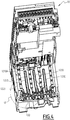
- the figures 1 and 2 represent a control unit 1 for a multipole circuit breaker.
- a multipole electric circuit breaker comprises, for each electrical pole, power input and output terminals, which are selectively connected or electrically isolated from each other by separable movable contacts of the circuit breaker.
- Unit 1 is intended to be associated with such a circuit breaker D, visible at the figure 3 , to control the opening of the circuit breaker, that is to say the separation of the power input and output terminals of each pole, in case of detection of an operating anomaly such as an overcurrent or a short circuit -circuit, to prevent the flow of electric current between these terminals.
- the unit 1 is associated with the circuit breaker D to form an electrical assembly.
- the circuit breaker D then comprises the unit 1.
- control unit 1 is also configured to measure physical quantities representative of the current flowing in the circuit-breaker D, in order to establish statistics on the operation of the circuit-breaker D, for example to determine electric currents, electrical voltages , electrical powers or instantaneous energies or count the number of opening / closing cycles of the circuit breaker D.
- the unit 1 is adapted to be electrically connected to the input terminals of the circuit breaker D.
- the circuit breaker D is a multipole circuit breaker configured to operate with a polyphase alternating electric current, for example three-phase.
- the circuit breaker D comprises three electric poles respectively associated with electrical phases P1, P2 and P3, and an electrical pole associated with a neutral phase PN.
- the control unit 1 comprises a central body 10 and several removable modules 20, 30, 40, 50, 60 and 70.
- the number of modules may be different.
- Each of these modules is able to fulfill a particular predefined function, explained in more detail in the following.
- Each of the removable modules 20, 30, 40, 50, 60 and 70 is movable between a position inserted into the central body 10 and a position removed from the central body 10.
- the removable module In the inserted position, the removable module is received in a corresponding housing of the central body 10 or in a corresponding housing of another removable module itself already received in the central body 10. The removable module is then electrically connected to components of unit 1 contained in the central body 10.
- the removable module In the withdrawn position, the removable module is outside the central body 10 and is not electrically connected to a component of the unit 1 contained in the central body 10.
- the central body 10 comprises a control device 110 and an interconnection device 120.
- the control device 110 is configured to measure the operating state of the circuit breaker D, and in particular the value of current flowing in the course of time in this circuit breaker D, and to trigger the opening of the circuit breaker D when a malfunction is detected during this measurement.
- the control device 110 comprises a measurement circuit 1101, a common power supply bus 1102, and a signal processing calculation unit. 1104, which are here provided on an electronic card 1103 of the control device 110.
- the electronic card 1103 comprises a rigid support, for example of the PCB type for "Printed Circuit Board” in English. This electronic card 1103 extends essentially in a geometric plane P.
- the electronic card 1103 extends over the entire length of the control device 110 and the central body 10, the latter having an oblong shape according to the geometric plane P.
- the geometric plane P extends parallel to a front face of the circuit breaker D, in a vertical direction.
- the measuring circuit 1101 is adapted to measure the value of a voltage that is supplied on one of its inputs and, in response, to output a signal representative of the measured voltage value to the computing unit 1104.
- the computing unit 1104 is programmed to automatically determine an operating state of the circuit breaker from the measured voltage value. For example, the calculation unit 1104 controls the opening of the circuit breaker D, if the measured voltage value is greater than a predefined threshold, indicating a safety fault, such as a voltage surge or drop in the circuit breaker D
- the computing unit 1104 here comprises a programmable microcontroller.
- control of the circuit breaker D by the control unit 110 is achieved through a wired connection, not shown, between the control unit 110 and a dedicated interface of the circuit breaker D.
- the common power supply bus 1102 is configured to distribute a power supply to the various elements of the control circuit 110, such as the control circuit 1101 or the calculation unit 1104.
- the power supply bus 1102 is also configured to distribute a power supply to the additional modules 30, 40, 50 and 60 to ensure operation when they are in the inserted position.
- the interconnection device 120 is configured to be electrically connected to the circuit breaker D, so as to collect primary electrical voltages V1 from the circuit breaker D associated with the power terminals of the circuit breaker D. This connection is here made by means of a connector wire-to-card 130.
- primary electrical voltage of the electrical voltages whose maximum amplitude is greater than or equal to 100 volts or 240 volts or 400 volts. These primary electrical voltages correspond to those coming from the circuit breaker D.
- the circuit breaker D is a low-voltage and high-current circuit breaker adapted to operate with electrical voltages of maximum amplitude less than or equal to 690 Volts AC.
- these primary voltages V1 are differences in electrical potential between two phases of the polyphase electric current and are therefore themselves polyphase.
- secondary electrical voltage designates an alternating or continuous electrical voltage, the maximum amplitude of which is less than or equal to 20 volts or 30 volts.
- the primary voltages V1 from the circuit-breaker D during its operation are too high to directly supply the control device 110.
- the measuring circuit 1101 can not directly receive the primary voltages V1 directly.
- the primary voltages V1 must therefore be converted into a secondary voltage.
- the primary voltages because of their high value, present a risk of electrical safety for a user of the unit 1 if it comes into contact with them.
- the interconnection device 120 therefore also has the function of being electrically connected to the circuit-breaker D in order to collect the primary voltages V1 and to generate secondary voltages V2 from these primary voltages V1 and to supply the secondary voltages V2 generated to the circuit.
- the purpose of the interconnection device 120 is to share these primary voltages V1 collected with the removable power supply module 20, when the latter is in the inserted position in the central body 10.
- the power supply module 20 is itself configured to convert the primary voltages V1 into an additional secondary voltage V2 ', also called additional secondary electrical voltage, for supplying the control device 110.
- the additional secondary voltage V2' is not not necessarily identical to the secondary electrical voltage V2 supplied by the interconnection device 120.
- the removable power supply module 20 comprises a primary connection interface 201, a secondary connection interface 202, a power converter 203 which are here fixed on a rigid support 205 ( Figure 2 ) and housed inside a housing 204 ( Figure 2 ) of the removable power supply unit 20.
- the support 205 here has a planar shape and extends in a geometrical plane P 'perpendicular to the geometric plane P.
- the geometric plane P' corresponds to a horizontal plane when the unit 1 is in a configuration assembled with the circuit breaker D.
- the power converter 203 is adapted to transform a primary voltage V1 received from the primary connection interface 201 into an additional secondary voltage V2 ', which is then delivered to the secondary connection interface 202.
- the power converter 203 is a voltage transformer.
- the power bus 1102 is configured to be powered by an additional DC secondary voltage V2 'of amplitude equal to 24 volts.
- the power supply bus 1102 includes additional power converters adapted to convert this additional secondary voltage V2 'into a DC voltage of a lower value, for example equal to 3.3 volts, in order to power certain elements of the device. order 110.
- the primary connection 201 and secondary 202 interfaces are connected, respectively, to the interconnection device 120 and the control device 110.
- the primary connection 201 and secondary 202 interfaces are disconnected, respectively, from the interconnection device 120 and control device 110.
- the power bus 1102 is adapted to be supplied with a secondary voltage supplied by the module 20 when the latter is in the inserted position.
- the bus 1102 is advantageously adapted to continue to be supplied with energy when the module 20 is removed from the central body 10.
- this supply is made by the power supply module 20 when the latter is present in the unit 1.
- the power supply bus 1102 is also adapted to be supplied by a voltage from a power source.
- auxiliary power supply S ( figure 3 ). These auxiliary power sources S can be used in addition to or in replacement of the power supply module.
- a first example of an auxiliary power source S is an integrated current sensor within the circuit breaker, such as a current transformer, which generates a voltage from the electric power current flowing in the circuit breaker.
- a source in known manner, operates only when the circuit breaker is in the closed state and an electric current flows between the input and output terminals of the circuit breaker.
- a second example of an auxiliary power source S is a backup battery incorporated in the control unit 1 and not shown.
- a third example of an auxiliary supply source S may be an auxiliary supply module connected to an external power supply, for example from the electrical panel in which the unit 1 and the circuit breaker D are installed.
- This electrical source can be associated with an inverter or a backup power supply.
- a fourth example of an auxiliary power source S is provided by a user of the unit 1, by means of a USB data link, for "Universal Serial Bus" in English, for example when this user connects to the device.
- command 110 a computer terminal for performing maintenance diagnostic operations of the control unit 1.
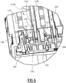
- the Figures 4 to 9 illustrate in more detail the interconnection device 120.
- the interconnection device 120 comprises input contact pads 1221 adapted to be electrically connected to power input terminal pads of the multipole electrical circuit breaker D to receive the primary electrical voltages from the circuit breaker D.
- the Interconnection device 120 comprises four input contact pads 1221 each associated with one of the electrical phases P1, P2, P3 and the neutral phase PN.
- the interconnection device 120 also has output contact pads 1222 electrically connected to the measurement circuit 1001 by means of wire connections, not shown.
- the interconnection device 120 furthermore comprises a power electrical circuit 1220, connected between the input contact pads 1221 and the output contact pads 1222.
- This electrical power circuit 1220 is here a voltage divider bridge formed by a plurality of electrical resistors 1223 and 1223 '.
- connection device 120 here comprises a support 1210 of planar shape on which is formed the electric power circuit 1220, the input contact pads 1221 and the output contact pads 1122.
- the support 1210 is rigid.
- the support 1210 extends here in the geometrical plane P '.
- the input contact pads 1221 are provided on the first face 1210A, at an edge of the support 1210.
- the output contact pads 1222 are also formed on the first face 1210A, at a location different from that of the pads. input contact 1221.
- the resistors 1223 are arranged on the first face 1210A, while the resistors 1223 'are arranged on the second face 1210B.
- the resistors 1223 are arranged to form branches of the divider bridge of the power circuit 1220, each associated with one of the electrical phases P1, P2, P3 and PN. More precisely, the resistors 1223 and 1223 'are, within each branch of the power circuit 1220, electrically connected to one another as well as to the input contact pads 1221 and the output contact pads 1222 by means of electrically conductive tracks arranged on the first and second corresponding faces 1210A and 1210B of the support 1210. The position of each resistor 1223, 1223 'ensures electrical isolation between them and between each branch.
- the support 1210 comprises a main part from which extend four longitudinal extensions, or branches, parallel to each other and separated by 1210E spacings, so that the support 1210 has a four-branch E shape.
- Each of the branches is associated with an electrical phase of the circuit P1, P2, P3 and PN.
- each branch comprises a single input contact pad 1221 and also comprises the resistors 1223 associated with this electrical phase.
- the output contact pads 1222 are arranged next to each other at the main part of the support 1210.
- the neutral phase PN is associated with one of the central branches of the support 1210 and not placed on one of the branches which lie on the outer edges of the support 1210.
- there are at least two electrical phases P1, P2 and P3 are separated from each other by the neutral phase PN, which improves the electrical safety, especially vis-à-vis the formation of electric arc between the connectors of these different phases.
- resistors 1223, 1223 ' are used for each of the electrical phases P1, P2, P3 and PN.
- this number may be different.
- the resistors 1223 'which are arranged on the second face 1210B can be omitted. They are typically arranged on this face 1210B when there is not enough space on the first face 1210A to accommodate them.
- the support 1210 has a length D1 equal to 40mm and a width D2 equal to 54mm. This length and this width are here measured in the plane of the support 1210.
- the interconnection device 110 also comprises partitions, or longitudinal insulating screens 1230, which are arranged along the face 1210A of the support 1210, starting from the edge of the support 1210 and extending perpendicularly relative to the support 1210. These longitudinal screens 1230 are here three in number and are identical to each other.
- each screen 1230 is greater than or equal to 8 mm or 8.5 mm,
- the isolation screens 1230 extend over at least 50% of the length of the support 1210, preferably at least 80% the length of the support 1210.
- insulation screens 1230 are made of a high temperature electrically insulating material and flame retarded, for example plastic such as crosslinked polyamide, or polycarbonate loaded glass fiber.
- plastic such as crosslinked polyamide, or polycarbonate loaded glass fiber.
- crosslinked polyamide 6.6 also noted “PA 6.6”
- PC GF10 polycarbonate PC GF10.
- the screens 1230 are integral with a housing of the central body 10.
- Each isolation screen 1230 is received inside a recess 1210E of the support 1210 which separates the parallel branches of the support 1210.
- the screens 1230 are distinct from the support 1210.
- the screens 1230 may be provided directly on the support 1210.
- the isolation screens 1230 thus have a shape complementary to that of the spacings 1210E of the support 1210.
- the screens 1230 transversely separate the input contact pads 1221 from each other.
- these screens 1230 extend along the length of the support 1210, they separate transversely from each other the rows of resistors 1223 of the power circuit 1220 which are formed on the face 1210A.
- the longitudinal screens 1230 thus create an electrically insulating barrier which is interposed between the input contact pads 1221 associated with the electrical phases P1, P2, P3 and PN and which increases the point-to-point distance between these input contact pads. 1221.
- the longitudinal screens 1230 increase the line-of-flight distance between these input contact pads 1221. The same is true with respect to the branches of the power circuit 1220.
- the notions of distance in the air and creepage are well known to those skilled in the art and are not examples defined in more detail in the IEC 60335 standard of the International Electrotechnical Commission.
- the distance in the air corresponds to the point-to-point distance between two electrical contacts while the creepage distance corresponds to the shortest distance between these two electrical contacts obtained while traveling along the different materials that are between these two electrical contacts
- the screens 1230 Thanks to the screens 1230, and in particular their height, relative to the dimensions of the housing in which the support 1210 of the interconnection device 120 is received within the central body 10, it avoids the formation of direct lines in the air between two consecutive input contact pads 1221 since the latter are electrically separated from each other by the screens 1230. Moreover, thanks to the length of these screens 1230, the length of the lines of Permitted leakage within this 1210A face is greater than or equal to 28mm or 32mm.
- the wire-to-card connector 130 comprises a housing 1301 inside which are formed separate housings 1302, separated from each other, over a part of their length, by external spacings 1303.
- the outer spacings 1303 are of complementary shape to the ends of longitudinal insulation screens 1230.
- Each of the housings 1302 of the connector 130 contains an electrical connection blade 1304, intended to come into contact with a corresponding input contact pad 1221.
- This contact blade 1304 is electrically connected to an electric cable, itself electrically connected to a corresponding power input terminal of the circuit breaker D.
- the connector 130 comprises four housings 1302, each containing a blade 1304 each associated with one of the electrical phases P1, P2, P3 and PN.
- the connector 130 also includes alignment elements 1305, which allow the guiding and positioning of the connector 130 on the bort of the support 1210.
- the connector 130 is removable, that is to say it is movable, reversibly and selectively between a connected position and a disconnected position.
- the connector 130 in particular because of its shape, can be inserted into its connected position only if it is oriented in a predefined direction, thereby providing a keying function.
- the ends of the branches of the support 1210 are received inside the corresponding housings 1302.
- the input contact pads 1210 placed on these ends of the branches of the support 1210 are also received inside the housing. corresponding 1302 and are in electrical contact with the electric blades 1304, so as to provide electrical connection with the corresponding terminals of the circuit breaker D.
- the ends of the screens 1230 are received within the outer spaces 1303.
- the housing 1301 is not fully illustrated and only its outer contour is shown schematically by a solid line.
- the ends of the branches of the support 1210 as well as the input contact pads 1221 are located outside the housings 1302. Similarly, the blades 1304 are disconnected from the contact pads 1221 , thereby preventing an electrical connection between the terminals of the circuit breaker D and the interconnection device 120.
- the length of the creepage line that is to be traveled is lengthened to electrically connect the studs to the ambient air. 1221. This further reduces the risk of forming a short circuit between contact pads 1221 or adjacent blades 1304 associated with electrical phases P1, P2, P3.
- the length L of the creepage distances between two blades 1304 is here greater than or equal to 28 mm or, preferably, to 32 mm.
- the interconnection device 120 also comprises an isolation wall 1240, illustrated in FIG. figure 5 which is interposed against the input contact pads 1221 and the output contact pads 1222.
- This wall 1240 extends perpendicular to the face 1210A.
- the wall 1240 is here made of an electrically insulating material, for example a plastic material, such as the PA 66 crosslinked polyamide, or the PC GF10 fiberglass-loaded polycarbonate previously described.
- the wall 1240 is formed directly on the face 1210A of the support 1210, on the main part of the support 1210.
- This wall 1240 has a part central, substantially planar shape, and side flaps inclined relative to the central portion, so as to surround the area of the face 1210A of the support 1210 on which are formed the electrical contacts 1222.
- the wall 1240 has a light color, such as white or gray, to facilitate its automatic detection during manufacturing steps by a manufacturing device.
- the wall 1240 has a height, measured perpendicularly to the surface of the face 1210A, that is to say perpendicularly to the geometrical plane P ', which is greater than or equal to 50% or, preferably, 80%, or preferably still at 90%, the free distance between the face 1210A and a cover at least partially covering this face 1210A this cover forming part of the central body 10.
- the wall 1240 prevents the formation of an electric arc or a short circuit between one of the input contact pads 1221 and one of the output contact pads 1222. This is achieved by the fact that the wall 1240 has a height sufficient to fit on the straight line in the ambient air connecting each of the input contact pads 1221 to each output contact pads 1222. Thus, it provides improved electrical insulation between the primary voltages and secondary voltages.
- the modular design of the unit 1 ensures a good compactness and size of the unit 1.
- compactness of the unit 1 introduces a risk of short circuit between the areas of the device. interconnection 120 which are exposed to the primary voltage V1 and the areas of the interconnection device 120 which are exposed to the secondary voltage V2, because these areas are closer to each other because of this compactness.
- the distance that must be traveled in the ambient air is lengthened to connect electrically, for example for an electric arc, between these two zones. This reduces the risk of occurrence of such a short circuit and increases the electrical safety of the unit 1.
- the distance in the air between a contact pad 1221 and a contact pad 1222 is greater than or equal to 25 mm.
- the distance of creepage between an input contact pad 1221 and a contact pad 1222 is greater than or equal to 28 mm, preferably 32 mm.
- this distance may be different, depending on the materials used to form the support 1210 and the wall 1240.
- the support 1210 comprises gilding 1251 of an electrically conductive material, such as gold, which are formed on a wafer 1210C perpendicular to the lateral edge of the support 1210. This wafer 1210C extends perpendicularly to the faces 1210A and 1210B.
- an electrically conductive material such as gold
- Each gilding 1251 is electrically connected to an input contact pad 1221 by means of an electrically conductive track formed on the face 1210A. These gilding 1251 serve to enable a test of the operation of the circuit 1220 during a manufacturing step of the unit 1. This test is typically performed by means of an automated test apparatus for which the positioning of the gilding on the wafer 1210 allows easier electrical connection than having to connect to contact pads 1221.
- the support 1210 comprises chamfers 1252 formed on the edges of the support 1210 at the level of the slice 1210C. These chamfers 1252 allow easier guiding and fixing of the connector 130.
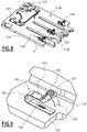
- the figure 8 represents the second face 1210B of the interconnection device 120.
- the interconnection device 120 comprises unitary flexible blade electrical connectors 1260, adapted to provide the electrical connection between the interconnection device 120 and the primary interconnection interface 201 of the removable power supply module 20 when this module is connected.
- removable power supply 20 is in its inserted position in the central body 10.
- the interconnection device 120 comprises three flexible connectors 1260, each associated with one of the electrical phases P1, P2 and P3.
- no flexible connector 260 is associated with the neutral phase PN.
- Each connector 1260 is fixed integrally to the support 1210, on the second face 1210B, at one end of the corresponding branch of the support 1210.
- the connector 1260 is for example welded to the face 1210B of the support 1210 by means of a weld or brazing.
- the connectors 1260 are aligned with each other and are distant from each other. Preferably, the connector 1260 located at the central branches is shifted in the alignment direction of the connectors 1260, so that it is not placed too close to the immediately adjacent connector 1260.
- Each of the connectors 1260 is electrically connected to the corresponding input contact pad 1221 located on the opposite face 1210A, for example by means of a through connection formed through the support 1210.
- each connector 1260 comprises a fixed base 1261 secured to the face 1210B of the support 1210, a curved portion 1262, for example a C-shaped, and a deformable upper portion 1263.
- the upper portion 1263 is deformable, resiliently and reversibly, between a depressed position and a relaxed position.
- the connector 1260 is illustrated in its rest position.
- the dashed lines 1260 represent the position of the contour of the upper portion 1263 when the latter is in its depressed position.
- the connector 1260 is in the depressed position when the removable power supply module 20 is in the inserted position
- connection with the primary connection interface 201 of the power supply module 20 is made by contact with the upper part 1263.
- the primary connection interface 201 of the power supply module 20 comprises a rigid plate made of a material electrically conductive.
- each plate of the primary connection interface 201 is pressed on the upper part 1263, so as to deform it towards its depressed position, to ensure electrical conduction .
- the bent portion 1262 comprises a planar zone 1264.
- these dimensions of this planar zone 1264 are such that a disk with a diameter greater than or equal to 2 mm can be inscribed therein.
- Such a flat portion 1264 facilitates the gripping of the connector 1260 by an automatic laying machine, the latter being typically provided with a gripping member equipped with a suction nozzle or a suction cup.
- the positioning of the connectors 1260 on the support 1210 is simplified during an industrial manufacturing step of the unit 1.
- the upper portion 1263 comprises a boss 1265 which protrudes with respect to the upper portion 1263, towards the outside of the connector 1260, that is to say opposite the base 1261.
- This boss 1265 makes it possible to ensure better electrical contact with the primary connection interface 201, in particular to ensure a point electrical contact. This reduces the risk of false contact and therefore malfunction of the power supply module 20. Thus, the reliability of the unit 1 is increased.
- the base 1261 has a through oblong hole 1266 which has a circumference greater than or equal to 4.5 mm.
- Such an orifice 1266 makes it possible to ensure that the welding or brazing material used to weld the connector 1260 to the support 1210 is raised. This material thus rises on the walls of the orifice 1266 as far as on an upper face of the base 1261. The The quality of the electrical contact between the connector 1260 and the input contact pad 1221 is thus improved.
- the connector 1260 is here made of metallic material, preferably in a beryllium copper alloy.
- a beryllium copper alloy has the advantage of ensuring good elasticity, while having satisfactory electrically conductive properties. Because of this good elasticity, it limits the risk of plastic deformation, that is to say irreversible, of the upper portion 1263 when it is subject to significant deformation and repeated between these two positions. Thus, the durability and reliability of the unit 1 are improved.
- the electrical connections within the central body 10 are made either by electrically conductive tracks provided on the supports, or by means of unitary connectors. It is therefore not necessary to use wires or wired connections within the unit 1. This reduces on the one hand its size, and on the other hand ensures a modular structure, in which modules can be selectively removed to add in a simplified manner by a user of the unit 1 during the operation of the unit 1 without it being necessary to modify the wiring each time.
- connectors are also adapted to support a high number of insertion and removal cycle of the various modules, ensuring a satisfactory longevity of the unit 1.
- the unit 1 further comprises a configuration module 30, a user interface module 40, a short-circuit detection module 50, an additional module 60 and a cover 70.
- each of these modules comprises an electronic card and piston type connectors for making the data and / or power connections with the control device of the central body 10.
- the module 30 also comprises here an electronic card, not shown.
- the module 50 comprises an electrically insulating screen 53 which covers the electronic card 51. This protects the electronic card 51 when the module 50 is removed from the central body 10, while having a smaller footprint than a plastic housing.
Landscapes
- Physics & Mathematics (AREA)
- General Physics & Mathematics (AREA)
- Engineering & Computer Science (AREA)
- Theoretical Computer Science (AREA)
- Microelectronics & Electronic Packaging (AREA)
- Breakers (AREA)
- Details Of Connecting Devices For Male And Female Coupling (AREA)
Applications Claiming Priority (1)
| Application Number | Priority Date | Filing Date | Title |
|---|---|---|---|
| FR1658076A FR3055420B1 (fr) | 2016-08-31 | 2016-08-31 | Unite de controle d'un disjoncteur electrique et disjoncteur comportant une telle unite de controle |
Publications (2)
| Publication Number | Publication Date |
|---|---|
| EP3290935A1 true EP3290935A1 (de) | 2018-03-07 |
| EP3290935B1 EP3290935B1 (de) | 2021-10-06 |
Family
ID=57286657
Family Applications (1)
| Application Number | Title | Priority Date | Filing Date |
|---|---|---|---|
| EP17188641.9A Active EP3290935B1 (de) | 2016-08-31 | 2017-08-30 | Kontrolleinheit eines elektrischen trennschalters, und trennschalter, der eine solche kontrolleinheit umfasst |
Country Status (4)
| Country | Link |
|---|---|
| US (1) | US10908215B2 (de) |
| EP (1) | EP3290935B1 (de) |
| CN (1) | CN107797053B (de) |
| FR (1) | FR3055420B1 (de) |
Cited By (5)
| Publication number | Priority date | Publication date | Assignee | Title |
|---|---|---|---|---|
| EP4625642A2 (de) | 2024-03-28 | 2025-10-01 | Schneider Electric Industries Sas | Batteriemodul für eine steuereinheit eines elektrischen schutzschalters, steuereinheit und elektrischer schutzschalter dafür |
| EP4625460A1 (de) | 2024-03-28 | 2025-10-01 | Schneider Electric Industries Sas | Steuereinheit für einen elektrischen schutzschalter und elektrischer schutzschalter dafür |
| EP4625461A1 (de) | 2024-03-28 | 2025-10-01 | Schneider Electric Industries Sas | Steuereinheit für einen elektrischen schutzschalter und elektrischer schutzschalter dafür |
| EP4625459A1 (de) | 2024-03-28 | 2025-10-01 | Schneider Electric Industries Sas | Steuereinheit für einen elektrischen schutzschalter und elektrischer schutzschalter dafür |
| EP4625465A1 (de) | 2024-03-28 | 2025-10-01 | Schneider Electric Industries Sas | Steuereinheit für einen elektrischen leistungsschalter und zugehöriger elektrischer leistungsschalter |
Families Citing this family (7)
| Publication number | Priority date | Publication date | Assignee | Title |
|---|---|---|---|---|
| US9890575B2 (en) * | 2013-12-09 | 2018-02-13 | Viking Access Systems, Llc | Movable barrier operator with removable power supply module |
| DE102020103491A1 (de) * | 2020-02-11 | 2021-08-12 | Dehn Se + Co Kg | Anordnung zur Bewertung des Zustandes und der Qualität von Niederspannungsnetzen |
| FR3123757A1 (fr) * | 2021-06-02 | 2022-12-09 | Hager-Electro Sas | Ensemble comprenant un appareillage électronique de protection et un module de contacts |
| FR3160822B1 (fr) * | 2024-03-28 | 2026-03-27 | Schneider Electric Ind Sas | Dispositif d’isolation pour un compartiment à pile, compartiment à pile, appareil électrique et disjoncteur électrique associés |
| CN118707321B (zh) * | 2024-08-29 | 2024-11-22 | 安徽徽电科技股份有限公司 | 用于快速断路器永磁保持机构动作的测试装置及测试方法 |
| CN119087210B (zh) * | 2024-11-06 | 2025-04-01 | 上海万控柜架有限公司 | 一种配电柜断路器在线监测装置 |
| CN121679315B (zh) * | 2026-02-12 | 2026-04-17 | 厦门安普格电气有限公司 | 一种分励脱扣线圈的电气性能测试装置 |
Citations (7)
| Publication number | Priority date | Publication date | Assignee | Title |
|---|---|---|---|---|
| US5331500A (en) * | 1990-12-26 | 1994-07-19 | Merlin Gerin | Circuit breaker comprising a card interfacing with a trip device |
| US5945650A (en) * | 1998-04-02 | 1999-08-31 | Siemens Energy & Automation,Inc. | Polyphase rotary switch including arc chamber system with arc grids, line shields and baffles |
| US6329810B1 (en) * | 1998-03-18 | 2001-12-11 | Square D Company | Modular sensor array, metering device and mounting and connection base |
| EP2079091A1 (de) * | 2008-01-10 | 2009-07-15 | Schneider Electric Industries SAS | Gehäuse eines elektronischen Auslösers für Sicherungsschalter, elektronische Auslösevorrichtung und Montageverfahren |
| EP2590198A1 (de) * | 2011-11-02 | 2013-05-08 | Eaton Industries GmbH | Leistungsschalter mit interner Spannungsmessung |
| EP2822018A1 (de) * | 2013-06-26 | 2015-01-07 | Schneider Electric Industries SAS | Entfernbare Vorrichtung für elektronischen Auslöser, Verfahren zur Stromversorgung einer solchen Vorrichtung, und Einheit, die einen solchen elektronischen Auslöser und eine solche entfernbare Vorrichtung umfasst |
| EP3018691A1 (de) * | 2014-11-10 | 2016-05-11 | Schneider Electric Industries SAS | Auslöser für elektrische umschaltvorrichtung, und elektrische umschaltvorrichtung, die einen solchen auslöser umfasst |
Family Cites Families (10)
| Publication number | Priority date | Publication date | Assignee | Title |
|---|---|---|---|---|
| US2755358A (en) * | 1950-06-06 | 1956-07-17 | Nat Acme Co | Shockproof overload relay |
| FR2661776B1 (fr) * | 1990-05-04 | 1996-05-10 | Merlin Gerin | Declencheur instantane d'un disjoncteur. |
| FR2756095B1 (fr) * | 1996-11-15 | 1998-12-24 | Schneider Electric Sa | Disjoncteur avec un bloc disjoncteur et des modules de traitement, de calibrage et de communication |
| US5982652A (en) * | 1998-07-14 | 1999-11-09 | American Power Conversion | Method and apparatus for providing uninterruptible power using a power controller and a redundant power controller |
| US7274112B2 (en) * | 2004-08-31 | 2007-09-25 | American Power Conversion Corporation | Method and apparatus for providing uninterruptible power |
| CA2579675A1 (en) * | 2004-09-10 | 2006-03-23 | Cooper Technologies Company | System and method for circuit protector monitoring and management |
| JP5727239B2 (ja) * | 2011-01-17 | 2015-06-03 | 中国電力株式会社 | 遮断器試験装置、プログラムおよび遮断器試験方法 |
| US8937822B2 (en) * | 2011-05-08 | 2015-01-20 | Paul Wilkinson Dent | Solar energy conversion and utilization system |
| CN202111467U (zh) * | 2011-06-23 | 2012-01-11 | 湖南新兴电器控制设备有限公司 | 一种多极低压断路器 |
| US10285241B2 (en) * | 2011-10-06 | 2019-05-07 | A9.Com, Inc. | Wireless lighting device with charging port |
-
2016
- 2016-08-31 FR FR1658076A patent/FR3055420B1/fr not_active Expired - Fee Related
-
2017
- 2017-08-15 US US15/677,184 patent/US10908215B2/en active Active
- 2017-08-30 EP EP17188641.9A patent/EP3290935B1/de active Active
- 2017-08-31 CN CN201710776815.2A patent/CN107797053B/zh active Active
Patent Citations (7)
| Publication number | Priority date | Publication date | Assignee | Title |
|---|---|---|---|---|
| US5331500A (en) * | 1990-12-26 | 1994-07-19 | Merlin Gerin | Circuit breaker comprising a card interfacing with a trip device |
| US6329810B1 (en) * | 1998-03-18 | 2001-12-11 | Square D Company | Modular sensor array, metering device and mounting and connection base |
| US5945650A (en) * | 1998-04-02 | 1999-08-31 | Siemens Energy & Automation,Inc. | Polyphase rotary switch including arc chamber system with arc grids, line shields and baffles |
| EP2079091A1 (de) * | 2008-01-10 | 2009-07-15 | Schneider Electric Industries SAS | Gehäuse eines elektronischen Auslösers für Sicherungsschalter, elektronische Auslösevorrichtung und Montageverfahren |
| EP2590198A1 (de) * | 2011-11-02 | 2013-05-08 | Eaton Industries GmbH | Leistungsschalter mit interner Spannungsmessung |
| EP2822018A1 (de) * | 2013-06-26 | 2015-01-07 | Schneider Electric Industries SAS | Entfernbare Vorrichtung für elektronischen Auslöser, Verfahren zur Stromversorgung einer solchen Vorrichtung, und Einheit, die einen solchen elektronischen Auslöser und eine solche entfernbare Vorrichtung umfasst |
| EP3018691A1 (de) * | 2014-11-10 | 2016-05-11 | Schneider Electric Industries SAS | Auslöser für elektrische umschaltvorrichtung, und elektrische umschaltvorrichtung, die einen solchen auslöser umfasst |
Cited By (11)
| Publication number | Priority date | Publication date | Assignee | Title |
|---|---|---|---|---|
| EP4625642A2 (de) | 2024-03-28 | 2025-10-01 | Schneider Electric Industries Sas | Batteriemodul für eine steuereinheit eines elektrischen schutzschalters, steuereinheit und elektrischer schutzschalter dafür |
| EP4625460A1 (de) | 2024-03-28 | 2025-10-01 | Schneider Electric Industries Sas | Steuereinheit für einen elektrischen schutzschalter und elektrischer schutzschalter dafür |
| EP4625461A1 (de) | 2024-03-28 | 2025-10-01 | Schneider Electric Industries Sas | Steuereinheit für einen elektrischen schutzschalter und elektrischer schutzschalter dafür |
| EP4625459A1 (de) | 2024-03-28 | 2025-10-01 | Schneider Electric Industries Sas | Steuereinheit für einen elektrischen schutzschalter und elektrischer schutzschalter dafür |
| EP4625465A1 (de) | 2024-03-28 | 2025-10-01 | Schneider Electric Industries Sas | Steuereinheit für einen elektrischen leistungsschalter und zugehöriger elektrischer leistungsschalter |
| FR3160806A1 (fr) | 2024-03-28 | 2025-10-03 | Schneider Electric Industries Sas | Unité de contrôle pour un disjoncteur électrique et disjoncteur électrique associé |
| FR3160805A1 (fr) | 2024-03-28 | 2025-10-03 | Schneider Electric Industries Sas | Module de batterie pour une unité de contrôle d’un disjoncteur électrique, unité de contrôle et disjoncteur électrique associés |
| FR3160808A1 (fr) | 2024-03-28 | 2025-10-03 | Schneider Electric Industries Sas | Unité de contrôle pour un disjoncteur électrique et disjoncteur électrique associé |
| FR3160804A1 (fr) | 2024-03-28 | 2025-10-03 | Schneider Electric Industries Sas | Unité de contrôle pour un disjoncteur électrique et disjoncteur électrique associé |
| FR3160807A1 (fr) * | 2024-03-28 | 2025-10-03 | Schneider Electric Industries Sas | Unité de contrôle pour un disjoncteur électrique et disjoncteur électrique associé |
| EP4625642A3 (de) * | 2024-03-28 | 2025-10-29 | Schneider Electric Industries Sas | Batteriemodul für eine steuereinheit eines elektrischen schutzschalters, steuereinheit und elektrischer schutzschalter dafür |
Also Published As
| Publication number | Publication date |
|---|---|
| FR3055420B1 (fr) | 2018-09-28 |
| CN107797053A (zh) | 2018-03-13 |
| US20180059185A1 (en) | 2018-03-01 |
| CN107797053B (zh) | 2022-03-04 |
| EP3290935B1 (de) | 2021-10-06 |
| FR3055420A1 (fr) | 2018-03-02 |
| US10908215B2 (en) | 2021-02-02 |
Similar Documents
| Publication | Publication Date | Title |
|---|---|---|
| EP3290935B1 (de) | Kontrolleinheit eines elektrischen trennschalters, und trennschalter, der eine solche kontrolleinheit umfasst | |
| EP0987803B1 (de) | Schutzvorrichtung für elektrischen Anlagen gegen Speisungsstörungen | |
| FR2974947A1 (fr) | Dispositif de connexion rapide pour un appareil electrique | |
| US12562516B2 (en) | Input connector with integrated residual current detection | |
| EP3531142B1 (de) | Vorrichtung zum messen mindestens einer elektrischen grösse eines stroms, der in mindestens einem elektrischen gerät fliesst | |
| CA1183229A (fr) | Connecteur electrique a couplage multiple et connecteurs multiples de mesure pour cartes de circuits d'equipement electronique monte en chassis en faisant application | |
| FR3014285A1 (fr) | Module a circuits relais electrique et centre electrique pour vehicule comprenant un tel module a circuits relais electrique. | |
| EP3576975B1 (de) | Elektrische anschlussvorrichtung mit eingebauter sperrfunktion | |
| CN103688414A (zh) | 具有能中断的电路的电连接模块 | |
| KR100715987B1 (ko) | 무정전 교체가 가능한 공동주택용 적산전력계 | |
| EP0193045B1 (de) | Elektrischer Uhren-Modul, ausgelegt zur Anpassung der Batterie-polarität an diejenige der Schaltung | |
| FR3063839B1 (fr) | Systeme de protection contre la foudre pour un aeronef | |
| EP2926151B1 (de) | Vorrichtung zur messung von mindestens einer elektrischen grösse eines stromes in einer elektrischen vorrichtung | |
| FR2800927A1 (fr) | Repartiteur de puissance electrique pour tiroir enfichable et tiroir enfichable | |
| FR2820210A1 (fr) | Unite mobile comprenant un dispositif de comptage et d'enregistrement de l'energie electrique prelevee | |
| CN221633194U (zh) | 配电盒 | |
| FR2754401A1 (fr) | Dispositif de connexion electrique entre un appareil de protection tel qu'un interrupteur differentiel et des appareils dependants tels que disjoncteurs divisionnaires et/ou fusibles divisionnaires | |
| FR3020725A1 (fr) | Boitier de connexion pour luminaire d'eclairage public | |
| JP2010237052A (ja) | プラグ受け | |
| JP6875197B2 (ja) | 導通チェッカー | |
| FR2552594A1 (fr) | Fiche de raccordement pour stator a contacts d'enroulements permanents | |
| FR3101192A1 (fr) | Appareil de coupure électrique à fusible | |
| FR3160804A1 (fr) | Unité de contrôle pour un disjoncteur électrique et disjoncteur électrique associé | |
| FR2879832A1 (fr) | Dispositif de deconnexion electrique pour compteur electrique polyphase | |
| EP3599629A1 (de) | Elektrische trennschaltervorrichtung für fahrzeug und entsprechendes fahrzeug |
Legal Events
| Date | Code | Title | Description |
|---|---|---|---|
| PUAI | Public reference made under article 153(3) epc to a published international application that has entered the european phase |
Free format text: ORIGINAL CODE: 0009012 |
|
| STAA | Information on the status of an ep patent application or granted ep patent |
Free format text: STATUS: THE APPLICATION HAS BEEN PUBLISHED |
|
| AK | Designated contracting states |
Kind code of ref document: A1 Designated state(s): AL AT BE BG CH CY CZ DE DK EE ES FI FR GB GR HR HU IE IS IT LI LT LU LV MC MK MT NL NO PL PT RO RS SE SI SK SM TR |
|
| AX | Request for extension of the european patent |
Extension state: BA ME |
|
| STAA | Information on the status of an ep patent application or granted ep patent |
Free format text: STATUS: REQUEST FOR EXAMINATION WAS MADE |
|
| 17P | Request for examination filed |
Effective date: 20180808 |
|
| RBV | Designated contracting states (corrected) |
Designated state(s): AL AT BE BG CH CY CZ DE DK EE ES FI FR GB GR HR HU IE IS IT LI LT LU LV MC MK MT NL NO PL PT RO RS SE SI SK SM TR |
|
| GRAP | Despatch of communication of intention to grant a patent |
Free format text: ORIGINAL CODE: EPIDOSNIGR1 |
|
| STAA | Information on the status of an ep patent application or granted ep patent |
Free format text: STATUS: GRANT OF PATENT IS INTENDED |
|
| INTG | Intention to grant announced |
Effective date: 20210518 |
|
| GRAS | Grant fee paid |
Free format text: ORIGINAL CODE: EPIDOSNIGR3 |
|
| GRAA | (expected) grant |
Free format text: ORIGINAL CODE: 0009210 |
|
| STAA | Information on the status of an ep patent application or granted ep patent |
Free format text: STATUS: THE PATENT HAS BEEN GRANTED |
|
| AK | Designated contracting states |
Kind code of ref document: B1 Designated state(s): AL AT BE BG CH CY CZ DE DK EE ES FI FR GB GR HR HU IE IS IT LI LT LU LV MC MK MT NL NO PL PT RO RS SE SI SK SM TR |
|
| REG | Reference to a national code |
Ref country code: GB Ref legal event code: FG4D Free format text: NOT ENGLISH |
|
| REG | Reference to a national code |
Ref country code: CH Ref legal event code: EP Ref country code: AT Ref legal event code: REF Ref document number: 1436664 Country of ref document: AT Kind code of ref document: T Effective date: 20211015 |
|
| REG | Reference to a national code |
Ref country code: DE Ref legal event code: R096 Ref document number: 602017047069 Country of ref document: DE |
|
| REG | Reference to a national code |
Ref country code: IE Ref legal event code: FG4D Free format text: LANGUAGE OF EP DOCUMENT: FRENCH |
|
| REG | Reference to a national code |
Ref country code: LT Ref legal event code: MG9D |
|
| REG | Reference to a national code |
Ref country code: NL Ref legal event code: MP Effective date: 20211006 |
|
| PG25 | Lapsed in a contracting state [announced via postgrant information from national office to epo] |
Ref country code: RS Free format text: LAPSE BECAUSE OF FAILURE TO SUBMIT A TRANSLATION OF THE DESCRIPTION OR TO PAY THE FEE WITHIN THE PRESCRIBED TIME-LIMIT Effective date: 20211006 Ref country code: LT Free format text: LAPSE BECAUSE OF FAILURE TO SUBMIT A TRANSLATION OF THE DESCRIPTION OR TO PAY THE FEE WITHIN THE PRESCRIBED TIME-LIMIT Effective date: 20211006 Ref country code: FI Free format text: LAPSE BECAUSE OF FAILURE TO SUBMIT A TRANSLATION OF THE DESCRIPTION OR TO PAY THE FEE WITHIN THE PRESCRIBED TIME-LIMIT Effective date: 20211006 Ref country code: BG Free format text: LAPSE BECAUSE OF FAILURE TO SUBMIT A TRANSLATION OF THE DESCRIPTION OR TO PAY THE FEE WITHIN THE PRESCRIBED TIME-LIMIT Effective date: 20220106 |
|
| PG25 | Lapsed in a contracting state [announced via postgrant information from national office to epo] |
Ref country code: IS Free format text: LAPSE BECAUSE OF FAILURE TO SUBMIT A TRANSLATION OF THE DESCRIPTION OR TO PAY THE FEE WITHIN THE PRESCRIBED TIME-LIMIT Effective date: 20220206 Ref country code: SE Free format text: LAPSE BECAUSE OF FAILURE TO SUBMIT A TRANSLATION OF THE DESCRIPTION OR TO PAY THE FEE WITHIN THE PRESCRIBED TIME-LIMIT Effective date: 20211006 Ref country code: PT Free format text: LAPSE BECAUSE OF FAILURE TO SUBMIT A TRANSLATION OF THE DESCRIPTION OR TO PAY THE FEE WITHIN THE PRESCRIBED TIME-LIMIT Effective date: 20220207 Ref country code: PL Free format text: LAPSE BECAUSE OF FAILURE TO SUBMIT A TRANSLATION OF THE DESCRIPTION OR TO PAY THE FEE WITHIN THE PRESCRIBED TIME-LIMIT Effective date: 20211006 Ref country code: NO Free format text: LAPSE BECAUSE OF FAILURE TO SUBMIT A TRANSLATION OF THE DESCRIPTION OR TO PAY THE FEE WITHIN THE PRESCRIBED TIME-LIMIT Effective date: 20220106 Ref country code: NL Free format text: LAPSE BECAUSE OF FAILURE TO SUBMIT A TRANSLATION OF THE DESCRIPTION OR TO PAY THE FEE WITHIN THE PRESCRIBED TIME-LIMIT Effective date: 20211006 Ref country code: LV Free format text: LAPSE BECAUSE OF FAILURE TO SUBMIT A TRANSLATION OF THE DESCRIPTION OR TO PAY THE FEE WITHIN THE PRESCRIBED TIME-LIMIT Effective date: 20211006 Ref country code: HR Free format text: LAPSE BECAUSE OF FAILURE TO SUBMIT A TRANSLATION OF THE DESCRIPTION OR TO PAY THE FEE WITHIN THE PRESCRIBED TIME-LIMIT Effective date: 20211006 Ref country code: GR Free format text: LAPSE BECAUSE OF FAILURE TO SUBMIT A TRANSLATION OF THE DESCRIPTION OR TO PAY THE FEE WITHIN THE PRESCRIBED TIME-LIMIT Effective date: 20220107 Ref country code: ES Free format text: LAPSE BECAUSE OF FAILURE TO SUBMIT A TRANSLATION OF THE DESCRIPTION OR TO PAY THE FEE WITHIN THE PRESCRIBED TIME-LIMIT Effective date: 20211006 |
|
| REG | Reference to a national code |
Ref country code: DE Ref legal event code: R097 Ref document number: 602017047069 Country of ref document: DE |
|
| PG25 | Lapsed in a contracting state [announced via postgrant information from national office to epo] |
Ref country code: SM Free format text: LAPSE BECAUSE OF FAILURE TO SUBMIT A TRANSLATION OF THE DESCRIPTION OR TO PAY THE FEE WITHIN THE PRESCRIBED TIME-LIMIT Effective date: 20211006 Ref country code: SK Free format text: LAPSE BECAUSE OF FAILURE TO SUBMIT A TRANSLATION OF THE DESCRIPTION OR TO PAY THE FEE WITHIN THE PRESCRIBED TIME-LIMIT Effective date: 20211006 Ref country code: RO Free format text: LAPSE BECAUSE OF FAILURE TO SUBMIT A TRANSLATION OF THE DESCRIPTION OR TO PAY THE FEE WITHIN THE PRESCRIBED TIME-LIMIT Effective date: 20211006 Ref country code: EE Free format text: LAPSE BECAUSE OF FAILURE TO SUBMIT A TRANSLATION OF THE DESCRIPTION OR TO PAY THE FEE WITHIN THE PRESCRIBED TIME-LIMIT Effective date: 20211006 Ref country code: DK Free format text: LAPSE BECAUSE OF FAILURE TO SUBMIT A TRANSLATION OF THE DESCRIPTION OR TO PAY THE FEE WITHIN THE PRESCRIBED TIME-LIMIT Effective date: 20211006 Ref country code: CZ Free format text: LAPSE BECAUSE OF FAILURE TO SUBMIT A TRANSLATION OF THE DESCRIPTION OR TO PAY THE FEE WITHIN THE PRESCRIBED TIME-LIMIT Effective date: 20211006 |
|
| PLBE | No opposition filed within time limit |
Free format text: ORIGINAL CODE: 0009261 |
|
| STAA | Information on the status of an ep patent application or granted ep patent |
Free format text: STATUS: NO OPPOSITION FILED WITHIN TIME LIMIT |
|
| 26N | No opposition filed |
Effective date: 20220707 |
|
| PG25 | Lapsed in a contracting state [announced via postgrant information from national office to epo] |
Ref country code: AL Free format text: LAPSE BECAUSE OF FAILURE TO SUBMIT A TRANSLATION OF THE DESCRIPTION OR TO PAY THE FEE WITHIN THE PRESCRIBED TIME-LIMIT Effective date: 20211006 |
|
| PG25 | Lapsed in a contracting state [announced via postgrant information from national office to epo] |
Ref country code: SI Free format text: LAPSE BECAUSE OF FAILURE TO SUBMIT A TRANSLATION OF THE DESCRIPTION OR TO PAY THE FEE WITHIN THE PRESCRIBED TIME-LIMIT Effective date: 20211006 |
|
| REG | Reference to a national code |
Ref country code: AT Ref legal event code: UEP Ref document number: 1436664 Country of ref document: AT Kind code of ref document: T Effective date: 20211006 |
|
| PG25 | Lapsed in a contracting state [announced via postgrant information from national office to epo] |
Ref country code: MC Free format text: LAPSE BECAUSE OF FAILURE TO SUBMIT A TRANSLATION OF THE DESCRIPTION OR TO PAY THE FEE WITHIN THE PRESCRIBED TIME-LIMIT Effective date: 20211006 |
|
| PG25 | Lapsed in a contracting state [announced via postgrant information from national office to epo] |
Ref country code: LU Free format text: LAPSE BECAUSE OF NON-PAYMENT OF DUE FEES Effective date: 20220830 |
|
| REG | Reference to a national code |
Ref country code: BE Ref legal event code: MM Effective date: 20220831 |
|
| PG25 | Lapsed in a contracting state [announced via postgrant information from national office to epo] |
Ref country code: IE Free format text: LAPSE BECAUSE OF NON-PAYMENT OF DUE FEES Effective date: 20220830 |
|
| PG25 | Lapsed in a contracting state [announced via postgrant information from national office to epo] |
Ref country code: BE Free format text: LAPSE BECAUSE OF NON-PAYMENT OF DUE FEES Effective date: 20220831 |
|
| PG25 | Lapsed in a contracting state [announced via postgrant information from national office to epo] |
Ref country code: HU Free format text: LAPSE BECAUSE OF FAILURE TO SUBMIT A TRANSLATION OF THE DESCRIPTION OR TO PAY THE FEE WITHIN THE PRESCRIBED TIME-LIMIT; INVALID AB INITIO Effective date: 20170830 |
|
| PG25 | Lapsed in a contracting state [announced via postgrant information from national office to epo] |
Ref country code: CY Free format text: LAPSE BECAUSE OF FAILURE TO SUBMIT A TRANSLATION OF THE DESCRIPTION OR TO PAY THE FEE WITHIN THE PRESCRIBED TIME-LIMIT Effective date: 20211006 |
|
| PG25 | Lapsed in a contracting state [announced via postgrant information from national office to epo] |
Ref country code: MK Free format text: LAPSE BECAUSE OF FAILURE TO SUBMIT A TRANSLATION OF THE DESCRIPTION OR TO PAY THE FEE WITHIN THE PRESCRIBED TIME-LIMIT Effective date: 20211006 |
|
| PG25 | Lapsed in a contracting state [announced via postgrant information from national office to epo] |
Ref country code: MT Free format text: LAPSE BECAUSE OF FAILURE TO SUBMIT A TRANSLATION OF THE DESCRIPTION OR TO PAY THE FEE WITHIN THE PRESCRIBED TIME-LIMIT Effective date: 20211006 |
|
| PGFP | Annual fee paid to national office [announced via postgrant information from national office to epo] |
Ref country code: DE Payment date: 20250827 Year of fee payment: 9 |
|
| PGFP | Annual fee paid to national office [announced via postgrant information from national office to epo] |
Ref country code: IT Payment date: 20250825 Year of fee payment: 9 |
|
| PGFP | Annual fee paid to national office [announced via postgrant information from national office to epo] |
Ref country code: GB Payment date: 20250826 Year of fee payment: 9 |
|
| PGFP | Annual fee paid to national office [announced via postgrant information from national office to epo] |
Ref country code: FR Payment date: 20250825 Year of fee payment: 9 Ref country code: AT Payment date: 20250819 Year of fee payment: 9 |
|
| PGFP | Annual fee paid to national office [announced via postgrant information from national office to epo] |
Ref country code: CH Payment date: 20250901 Year of fee payment: 9 |
|
| PG25 | Lapsed in a contracting state [announced via postgrant information from national office to epo] |
Ref country code: TR Free format text: LAPSE BECAUSE OF FAILURE TO SUBMIT A TRANSLATION OF THE DESCRIPTION OR TO PAY THE FEE WITHIN THE PRESCRIBED TIME-LIMIT Effective date: 20211006 |