EP3291006A1 - Pellikelherstellungsverfahren und verfahren zur herstellung einer photomaske mit pellikel - Google Patents
Pellikelherstellungsverfahren und verfahren zur herstellung einer photomaske mit pellikel Download PDFInfo
- Publication number
- EP3291006A1 EP3291006A1 EP16786296.0A EP16786296A EP3291006A1 EP 3291006 A1 EP3291006 A1 EP 3291006A1 EP 16786296 A EP16786296 A EP 16786296A EP 3291006 A1 EP3291006 A1 EP 3291006A1
- Authority
- EP
- European Patent Office
- Prior art keywords
- pellicle
- substrate
- sensitive adhesive
- pressure
- film
- Prior art date
- Legal status (The legal status is an assumption and is not a legal conclusion. Google has not performed a legal analysis and makes no representation as to the accuracy of the status listed.)
- Withdrawn
Links
Images


Classifications
-
- B—PERFORMING OPERATIONS; TRANSPORTING
- B23—MACHINE TOOLS; METAL-WORKING NOT OTHERWISE PROVIDED FOR
- B23K—SOLDERING OR UNSOLDERING; WELDING; CLADDING OR PLATING BY SOLDERING OR WELDING; CUTTING BY APPLYING HEAT LOCALLY, e.g. FLAME CUTTING; WORKING BY LASER BEAM
- B23K26/00—Working by laser beam, e.g. welding, cutting or boring
- B23K26/50—Working by transmitting the laser beam through or within the workpiece
- B23K26/53—Working by transmitting the laser beam through or within the workpiece for modifying or reforming the material inside the workpiece, e.g. for producing break initiation cracks
-
- G—PHYSICS
- G03—PHOTOGRAPHY; CINEMATOGRAPHY; ANALOGOUS TECHNIQUES USING WAVES OTHER THAN OPTICAL WAVES; ELECTROGRAPHY; HOLOGRAPHY
- G03F—PHOTOMECHANICAL PRODUCTION OF TEXTURED OR PATTERNED SURFACES, e.g. FOR PRINTING, FOR PROCESSING OF SEMICONDUCTOR DEVICES; MATERIALS THEREFOR; ORIGINALS THEREFOR; APPARATUS SPECIALLY ADAPTED THEREFOR
- G03F1/00—Originals for photomechanical production of textured or patterned surfaces, e.g., masks, photo-masks, reticles; Mask blanks or pellicles therefor; Containers specially adapted therefor; Preparation thereof
- G03F1/22—Masks or mask blanks for imaging by radiation of 100nm or shorter wavelength, e.g. X-ray masks, extreme ultraviolet [EUV] masks; Preparation thereof
- G03F1/24—Reflection masks; Preparation thereof
-
- B—PERFORMING OPERATIONS; TRANSPORTING
- B23—MACHINE TOOLS; METAL-WORKING NOT OTHERWISE PROVIDED FOR
- B23K—SOLDERING OR UNSOLDERING; WELDING; CLADDING OR PLATING BY SOLDERING OR WELDING; CUTTING BY APPLYING HEAT LOCALLY, e.g. FLAME CUTTING; WORKING BY LASER BEAM
- B23K26/00—Working by laser beam, e.g. welding, cutting or boring
- B23K26/0006—Working by laser beam, e.g. welding, cutting or boring taking account of the properties of the material involved
-
- C—CHEMISTRY; METALLURGY
- C09—DYES; PAINTS; POLISHES; NATURAL RESINS; ADHESIVES; COMPOSITIONS NOT OTHERWISE PROVIDED FOR; APPLICATIONS OF MATERIALS NOT OTHERWISE PROVIDED FOR
- C09J—ADHESIVES; NON-MECHANICAL ASPECTS OF ADHESIVE PROCESSES IN GENERAL; ADHESIVE PROCESSES NOT PROVIDED FOR ELSEWHERE; USE OF MATERIALS AS ADHESIVES
- C09J7/00—Adhesives in the form of films or foils
- C09J7/30—Adhesives in the form of films or foils characterised by the adhesive composition
- C09J7/38—Pressure-sensitive adhesives [PSA]
-
- G—PHYSICS
- G03—PHOTOGRAPHY; CINEMATOGRAPHY; ANALOGOUS TECHNIQUES USING WAVES OTHER THAN OPTICAL WAVES; ELECTROGRAPHY; HOLOGRAPHY
- G03F—PHOTOMECHANICAL PRODUCTION OF TEXTURED OR PATTERNED SURFACES, e.g. FOR PRINTING, FOR PROCESSING OF SEMICONDUCTOR DEVICES; MATERIALS THEREFOR; ORIGINALS THEREFOR; APPARATUS SPECIALLY ADAPTED THEREFOR
- G03F1/00—Originals for photomechanical production of textured or patterned surfaces, e.g., masks, photo-masks, reticles; Mask blanks or pellicles therefor; Containers specially adapted therefor; Preparation thereof
- G03F1/60—Substrates
-
- G—PHYSICS
- G03—PHOTOGRAPHY; CINEMATOGRAPHY; ANALOGOUS TECHNIQUES USING WAVES OTHER THAN OPTICAL WAVES; ELECTROGRAPHY; HOLOGRAPHY
- G03F—PHOTOMECHANICAL PRODUCTION OF TEXTURED OR PATTERNED SURFACES, e.g. FOR PRINTING, FOR PROCESSING OF SEMICONDUCTOR DEVICES; MATERIALS THEREFOR; ORIGINALS THEREFOR; APPARATUS SPECIALLY ADAPTED THEREFOR
- G03F1/00—Originals for photomechanical production of textured or patterned surfaces, e.g., masks, photo-masks, reticles; Mask blanks or pellicles therefor; Containers specially adapted therefor; Preparation thereof
- G03F1/62—Pellicles, e.g. pellicle assemblies, e.g. having membrane on support frame; Preparation thereof
-
- G—PHYSICS
- G03—PHOTOGRAPHY; CINEMATOGRAPHY; ANALOGOUS TECHNIQUES USING WAVES OTHER THAN OPTICAL WAVES; ELECTROGRAPHY; HOLOGRAPHY
- G03F—PHOTOMECHANICAL PRODUCTION OF TEXTURED OR PATTERNED SURFACES, e.g. FOR PRINTING, FOR PROCESSING OF SEMICONDUCTOR DEVICES; MATERIALS THEREFOR; ORIGINALS THEREFOR; APPARATUS SPECIALLY ADAPTED THEREFOR
- G03F1/00—Originals for photomechanical production of textured or patterned surfaces, e.g., masks, photo-masks, reticles; Mask blanks or pellicles therefor; Containers specially adapted therefor; Preparation thereof
- G03F1/62—Pellicles, e.g. pellicle assemblies, e.g. having membrane on support frame; Preparation thereof
- G03F1/64—Pellicles, e.g. pellicle assemblies, e.g. having membrane on support frame; Preparation thereof characterised by the frames, e.g. structure or material, including bonding means therefor
-
- B—PERFORMING OPERATIONS; TRANSPORTING
- B23—MACHINE TOOLS; METAL-WORKING NOT OTHERWISE PROVIDED FOR
- B23K—SOLDERING OR UNSOLDERING; WELDING; CLADDING OR PLATING BY SOLDERING OR WELDING; CUTTING BY APPLYING HEAT LOCALLY, e.g. FLAME CUTTING; WORKING BY LASER BEAM
- B23K2101/00—Articles made by soldering, welding or cutting
- B23K2101/36—Electric or electronic devices
- B23K2101/40—Semiconductor devices
-
- B—PERFORMING OPERATIONS; TRANSPORTING
- B23—MACHINE TOOLS; METAL-WORKING NOT OTHERWISE PROVIDED FOR
- B23K—SOLDERING OR UNSOLDERING; WELDING; CLADDING OR PLATING BY SOLDERING OR WELDING; CUTTING BY APPLYING HEAT LOCALLY, e.g. FLAME CUTTING; WORKING BY LASER BEAM
- B23K2103/00—Materials to be soldered, welded or cut
- B23K2103/50—Inorganic materials other than metals or composite materials
- B23K2103/52—Ceramics
-
- B—PERFORMING OPERATIONS; TRANSPORTING
- B23—MACHINE TOOLS; METAL-WORKING NOT OTHERWISE PROVIDED FOR
- B23K—SOLDERING OR UNSOLDERING; WELDING; CLADDING OR PLATING BY SOLDERING OR WELDING; CUTTING BY APPLYING HEAT LOCALLY, e.g. FLAME CUTTING; WORKING BY LASER BEAM
- B23K2103/00—Materials to be soldered, welded or cut
- B23K2103/50—Inorganic materials other than metals or composite materials
- B23K2103/56—Inorganic materials other than metals or composite materials being semiconducting
-
- G—PHYSICS
- G03—PHOTOGRAPHY; CINEMATOGRAPHY; ANALOGOUS TECHNIQUES USING WAVES OTHER THAN OPTICAL WAVES; ELECTROGRAPHY; HOLOGRAPHY
- G03F—PHOTOMECHANICAL PRODUCTION OF TEXTURED OR PATTERNED SURFACES, e.g. FOR PRINTING, FOR PROCESSING OF SEMICONDUCTOR DEVICES; MATERIALS THEREFOR; ORIGINALS THEREFOR; APPARATUS SPECIALLY ADAPTED THEREFOR
- G03F1/00—Originals for photomechanical production of textured or patterned surfaces, e.g., masks, photo-masks, reticles; Mask blanks or pellicles therefor; Containers specially adapted therefor; Preparation thereof
- G03F1/68—Preparation processes not covered by groups G03F1/20 - G03F1/50
- G03F1/80—Etching
Definitions
- the present invention relates to a method for producing a pellicle.
- patterning is performed by exposure through a photomask or a reticle.
- a foreign object is attached to a surface of the photomask or the reticle, the foreign object is transferred to a wafer each time the exposure to light is performed.
- a pellicle including a pellicle frame and a pellicle film is bonded such that the pellicle film is located several millimeters away from a surface of the photomask of the reticle.
- the pellicle In the case where the pellicle is located on at least a patterned surface of the photomask or the reticle, the foreign object attached to a surface of the pellicle is not focused on. Therefore, an image of the foreign object is not formed on a photoresist formed on the semiconductor wafer, and thus the circuit pattern is prevented from being defective.
- Such a pellicle-attached photomask is conventionally produced as follows.
- a pellicle frame having a shape corresponding to the photomask or the reticle and a thickness of about several millimeters is prepared.
- a pellicle film formed of a transparent polymer film of nitrocellulose or a cellulose derivative having a thickness of 10 ⁇ m or less is stretched on, and bonded to, one of two surfaces of the pellicle frame. Then, the other surface of the pellicle frame is bonded to the surface of the photomask or the reticle via an adhesive material.
- EUV light refers to light having a wavelength in a soft X-ray region or a vacuum ultraviolet region, more specifically, to light having a wavelength of approximately 13.5 nm ⁇ 0.3 nm.
- the resolution limit of patterning is about 1/2 of the wavelength of light used for exposure, and is considered to be about 1/4 of the wavelength of light used for exposure even in the case where a liquid immersion method is used.
- the wavelength of light used for exposure is expected to be about 45 nm at the minimum even when a liquid immersion method with ArF laser (wavelength: 193 nm) is used. In such a situation, the EUV lithography is expected as a revolutionary technology realizing significant size reduction over the conventional lithography technology.
- EUV light is easily absorbed to any type of substance and thus, in EUV lithography, exposure to light needs to be performed in a vacuum exposure device. Therefore, attachment of a pellicle to a photomask has been considered as not being indispensable.
- the EUV lithography is a process of high precision that has not been provided conventionally, and the number of times of stacking is larger. For these reasons, it is concerned in the semiconductor industry that LSIs or the like may not be produced at high yield in the case where merely the inside of the device is cleaned. It has been made clear that attachment of a pellicle to a photomask is indispensable. As described above, EUV light is easily absorbed to any type of substance.
- the pellicle film included in the pellicle needs to have a thickness of a nanometer order.
- the pellicle film needs to have a thickness of 10 nm or greater and 50 nm or less in order to have a transmittance of 90.0% or higher.
- a pellicle film is formed on a substrate by vapor deposition and the substrate is back-etched to have a frame shape, so that the pellicle film is exposed.
- a pellicle including a pellicle film is provided.
- the substrate needs to be trimmed (cut) to provide a part thereof that is required to form the pellicle, in order to match the shape of the pellicle to the shape of the photomask or the reticle.
- Patent Document 1 describes the following. A silicon substrate of an SOI structure is thinned to have a thickness of 50 ⁇ m, and a honey-comb structure is formed by DRIE (Deep Reactive Ion Etching) to form a pellicle film.
- DRIE Deep Reactive Ion Etching
- the pellicle film is cut have the same size as that of the pellicle frame.
- the substrate needs to be trimmed (cut) to provide a part thereof that is required to form the pellicle, in order to match the shape of the pellicle to the shape of the photomask or the reticle.
- Patent Literature 1 Japanese Laid-Open Patent Publication No. 2013-004893
- the substrate is cut by a mechanical force to provide a pellicle frame.
- this method has a problem that after the substrate is cut to provide the pellicle frame, foreign object particles are generated at the cut surface and attached to the pellicle film, which results in contaminating the pellicle film.
- the present invention for solving the above-described problem of the conventional technology has an object of suppressing foreign object particles generated at the timing of trimming from being attached to a pellicle film.
- An embodiment according to the present invention provides a method for producing a pellicle including a pellicle film and a pellicle frame supporting an outer peripheral portion of the pellicle film.
- the method comprises forming the pellicle film on a substrate, and bonding a pressure-sensitive adhesive sheet to each of two surfaces of the substrate, the pressure-sensitive adhesive sheet being elastic and having a pressure-sensitive adhesive force thereof decreased upon receipt of external stimulation; making a notch inside a part of the substrate, the part having the pressure-sensitive adhesive sheets bonded thereto; separating a substrate outer peripheral portion outer to the notch of the substrate, in a state where the pressure-sensitive adhesive sheets are bonded to the substrate, to form a pellicle frame; and stimulating the pressure-sensitive adhesive sheets to peel off the pressure-sensitive adhesive sheets.
- the method for producing a pellicle may further comprising etching the substrate, from a surface opposite to a surface on which the pellicle film is formed, to expose the pellicle film.
- the pressure-sensitive adhesive sheet may be bonded to each of the two surfaces of a portion of the substrate that is around the exposed portion of the pellicle film.
- the substrate may include a bridge portion coupling the pellicle frame and the substrate outer peripheral portion to each other; and making the notch inside the substrate may be making a notch inside the bridge portion.
- the pressure-sensitive adhesive sheets may be bonded to cover both of two surfaces and both of two side surfaces of the bridge portion.
- the bridge portion may be connected to each of four corners of the pellicle frame.
- the notch may be made inside the substrate by stealth dicing.
- the pressure-sensitive adhesive sheets may be antistatic.
- gas in a portion along which the substrate is separated may be absorbed by an absorption device.
- An embodiment according to the present invention provides a method for producing a pellicle-attached photomask, comprising joining the pellicle produced by the method for producing a pellicle according to any one of the above, and a photomask, to each other via a frame body attached to the pellicle frame.
- a method for producing a pellicle according to the present invention suppresses foreign object particles generated at the time of trimming from being attached to a pellicle film.
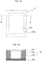
- FIG. 1A is a schematic view (plan view) of a pellicle-attached photomask produced in embodiment 1.
- FIG. 1B is a cross-sectional view of the pellicle-attached photomask in embodiment 1, taken along line A-A in FIG. 1A .
- the pellicle-attached photomask 1 includes a pellicle 10 and a photomask 104.
- the pellicle 10 is attached to a patterned surface of the photomask 104.
- the pellicle 10 includes a pellicle film 101, a pellicle frame 102 and a frame body 103.
- compound usable to form the pellicle film 101 include polymer compounds such as fluorine-based polymers, polyolefin, polyimide and the like; metal materials such as ruthenium, nickel, zirconium, titanium, molybdenum, niobium and the like; crystalline silicon (e.g., single crystalline silicon, polycrystalline silicon, etc.); amorphous silicon; diamond-like carbon (DLC); graphite; amorphous carbon; graphene; silicon carbide; silicon nitride; and the like.
- polymer compounds such as fluorine-based polymers, polyolefin, polyimide and the like
- metal materials such as ruthenium, nickel, zirconium, titanium, molybdenum, niobium and the like
- crystalline silicon e.g., single crystalline silicon, polycrystalline silicon, etc.
- amorphous silicon e.g., single crystalline silicon, polycrystalline silicon, etc.
- DLC diamond-like carbon
- the pellicle film 101 may include an anti-oxidant film or a heat dissipation film.
- the heat dissipation film is preferably formed of a material having a high heat radiation ratio or a material having a high heat conductivity.
- the heat dissipation film may be formed of, for example, substantially the same material as that of the anti-oxidant film, Rb, Sr, Y, Zr, Nb, graphite, graphene, or the like.
- the anti-oxidant film and the heat dissipation film may be formed on one surface, or both of two surfaces, of the pellicle film 101.
- the pellicle film 101 may contain one of, or two or more of, the above-listed elements and compounds.
- the pellicle-attached photomask 1 includes the pellicle 10 and the photomask 104.
- the pellicle 10 includes the pellicle film 101, the pellicle frame 102 and the frame body 103.
- the pellicle frame 102 is formed of silicon and has a thickness of about 0.7 mm, and supports an outer peripheral portion of the pellicle film 101.
- the frame body 103 is located between the photomask 104 and the pellicle frame 102.
- the thickness of the frame body 103 is determined such that the pellicle film 101 and the photomask 104 are away from each other by an interval of about 2 mm.
- the frame body 103 is joined to the photomask 104 and the pellicle frame 102 with an adhesive layer.
- An air hole communicating a space formed between the photomask 104 and the pellicle film 101, and the external space, to each other may be provided in the pellicle frame 102 or the frame body 103.
- a pellicle-attached photomask in this embodiment may be produced, for example, as described below with reference to FIG. 2A through FIG. 2E .
- the production method described below is an example.
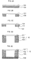
- FIG. 2A through FIG. 2E are schematic views each showing a step of the method for producing the pellicle-attached photomask in an embodiment.
- a substrate 105 is prepared, and the pellicle film 101 is formed on the substrate 105 ( FIG. 2A ).
- the substrate 105 is to become the pellicle frame 102 in a state where the production of the pellicle 10 is finished.
- the substrate 105 may be, for example, a silicon substrate, a sapphire substrate, a silicon carbide substrate or the like, but is not limited to any of these.
- the thickness of the substrate there is no specific limitation on the thickness of the substrate.
- the substrate is a silicon substrate
- an 8-inch wafer having a thickness of 725 ⁇ m conformed to the SEMI standards is preferably usable.
- a thinner substrate may be used.
- a substrate having a thickness of 50 ⁇ m or greater may be preferably used without being broken when the pellicle film is formed.
- the pellicle film 101 is formed on the substrate 105 by vapor deposition so as to have a thickness of 10 nm or greater and 50 nm or less. EUV light is easily absorbed to any type of substance. Therefore, the pellicle film 101 has, for example, a transmittance of 90% or higher for light having a wavelength of 13.5 ⁇ 0.3 nm.
- the substrate 105 having the pellicle film 101 formed thereon is etched from a surface opposite to the surface on which the pellicle film 101 is formed (back-etched), and the pellicle film 101 is exposed such that the substrate 105 is frame-shaped ( FIG. 2B ).
- the back-etching may be dry etching or wet etching.
- the back-etched substrate 105 is trimmed to separate a substrate outer peripheral portion 111 thereof to provide the pellicle frame 102, which needs to be joined with the frame body 103 ( FIG. 2C ).
- the method for the trimming will be described below in detail with reference to FIG. 3A, FIG. 3B , and FIG. 4A through FIG. 4D .
- the trimming is performed to provide the pellicle frame 102 after the back-etching.
- the back-etching may be performed after the trimming.
- the frame body 103 is joined with a surface of the pixel frame 102 opposite to a surface on which the pellicle film 101 is located ( FIG. 2D ).
- the frame body 103 is formed of a material that is tolerable against EUV light, is made flat easily and has a low rate of ion elution. It is also preferable that the frame body 103 is formed of a material tolerable against hydrogen radical because hydrogen gas is supplied to the inside of the exposure device in order to remove contaminants derived from carbon.
- the frame body 103 may be formed of a material that is usually usable for a pellicle frame.
- material usable for the frame body 103 include aluminum, aluminum alloys (5000-type, 6000-type, 7000-type, etc.), stainless steel, silicon, silicon alloys, iron, iron alloys, carbon steel, tool steel, ceramics, metal-ceramic composite materials, resins and the like.
- aluminum and aluminum alloys which are lightweight and rigid, are more preferable.
- the frame body 103 may have a protective film formed on a surface thereof.
- the protective film is preferably tolerable against hydrogen radical present in an exposure atmosphere and against EUV light.
- the protective film is, for example, an oxide film.
- the oxide film may be formed by a known method such as anodization or the like.
- the pellicle 10 including the pellicle film 101, the pellicle frame 102 and the frame body 103 obtained as a result of the trimming is joined with the photomask 104 ( FIG. 2E ). At this step, the pellicle-attached photomask 1 is produced.
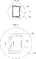
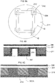
- FIG. 3A is a plan view showing a position at which a pressure-sensitive adhesive sheet is bonded in embodiment 1 according to the present invention.
- FIG. 3B is an enlarged view of FIG. 3A , and shows a portion to be subjected to the trimming.
- the one-dot chain line represents a region of the pellicle film 101 that is exposed by the etching performed on the substrate 105 from the opposite surface (by the back-etching performed on the substrate 105).
- FIG. 3A shows a position at which a frame-shaped pressure-sensitive adhesive sheet 106 is bonded.
- the pressure-sensitive adhesive sheet 106 is not limited to being frame-shaped and may cover a top surface of the pellicle film 101.
- the trimming shown in FIG. 2C is performed as follows.
- a pressure-sensitive adhesive sheet is bonded to each of two surfaces of the substrate 105 so as to cover a cut line L along which the substrate 105 and the pellicle film 101 are to be cut.
- the pressure-sensitive adhesive sheet 106 is bonded to the top surface of the pellicle film 101.
- a pressure-sensitive adhesive sheet 307 is bonded to a bottom surface of the substrate 105 (see FIG. 4A through FIG. 4C ).
- the pressure-sensitive adhesive sheets 106 and 107 are elastic and have a pressure-sensitive adhesive force thereof decreased upon receipt of external stimulation.
- the term “elastic” refers to having a tensile strength of 10 MPa or greater when having a Young's modulus is 100 MPa to 600 MPa and an elasticity of 20 to 40%.
- the “external stimulation” refers to ultraviolet light. The external stimulation is not limited to ultraviolet light and may be heat or the like.
- the pressure-sensitive adhesive sheet 106 and 107 may each be, for example, a sheet including a substrate film and a pressure-sensitive adhesive layer formed thereon.
- the substrate film may be any of a wide range of conventionally known substrate films, and may be, for example, a general-purpose polymer film such as a polyolefin-based film, an elastomer-based film or the like.
- material usable for the general-purpose polymer film include ethylene-based copolymers such as polyethylene, ethylene-vinyl acetate copolymer and the like; and general-purpose polymers such as polypropylene, polybutylene, ionomer; polybutadiene, polyethyleneterephthalate, polybutyleneterephthalate, polymethylpentene, polyurethane, and the like.
- the pressure-sensitive adhesive layer may be formed of any of a wide range of conventionally known pressure-sensitive adhesives, and may be formed of, for example, an acrylic resin-based pressure-sensitive adhesive.
- acrylic resin-based pressure-sensitive adhesive include acrylic resin-based polymers such as polymers having an acrylic acid ester as a polymer structural unit, acrylic acid ester-based copolymers, and the like; copolymers with functional monomers; and mixtures of such polymers.
- an ultraviolet-curable or thermally curable pressure-sensitive adhesive is preferable to use, for a pressure-sensitive adhesive layer. In the case where the pressure-sensitive adhesive layer is ultraviolet-curable or thermally curable, the following occurs.
- the pressure-sensitive adhesive layer may be cured by being irradiated with ultraviolet or being heated.
- the pressure-sensitive adhesive force of the pressure-sensitive adhesive layer is decreased, and thus the pressure-sensitive adhesive sheet is peeled off with no influence on the pellicle film or the pellicle frame.
- the pressure-sensitive adhesive sheet 107 is bonded to the entirety of the bottom surface of the substrate 105.
- the pressure-sensitive adhesive sheet 107 may be bonded in any manner as long as being located to face the pressure-sensitive adhesive sheet 106.
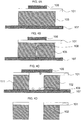
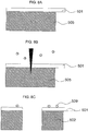
- FIG. 4A through FIG. 4C are schematic views showing a step of trimming in detail in the method for producing the pellicle-attached photomask in embodiment 1.
- FIG. 4A corresponds to a cross-section taken along line B-B in FIG. 3B .
- the pressure-sensitive adhesive sheets 106 and 107 are bonded to both of the two surfaces of the substrate 105.
- the pressure-sensitive adhesive sheets 106 and 107 are bonded to cover both of two surfaces of the portion including the cut line along which the cutting is to be performed for the trimming.
- the pressure-sensitive adhesive sheet 106 is bonded to a part of the top surface of the substrate 105.
- the pressure-sensitive adhesive sheet 106 may be bonded in any manner as long as covering the cut line.
- a notch is made inside the substrate 105 on which the pressure-sensitive adhesive sheets 106 and 107 are bonded ( FIG. 4B ). Since merely the notch is made inside in the substrate 105, no dust is generated from the surface of the substrate 105.
- the notch may be made in the substrate 105 by, for example, stealth dicing. Any other method may be used as long as the notch is made inside the substrate 105. According to the "stealth dicing", laser light is focused and directed to the inside of a processing target to form a quality-modified region inside the processing target along a line along which the processing target is to be cut. Then, the processing target is cut using the quality-modified region as a start point.
- the substrate 105 is expanded (pulled) together with the pressure-sensitive adhesive sheet 107 ( FIG. 4C ).
- the substrate outer peripheral portion 111 is separated and thus the pellicle frame 102 is formed.
- the substrate outer peripheral portion 111 is separated, foreign object particles 109 located in the notch inside the substrate 105 scatter as dust.
- the foreign object particles 109 are captured by the pressure-sensitive adhesive sheets 106 and 107.
- the expansion may be made by pushing the substrate 105 with a rod-like item from below the pressure-sensitive adhesive sheet 107.
- the pressure-sensitive adhesive sheet 107 may be expanded horizontally.
- the pressure-sensitive adhesive sheet 106 may be expanded together with the pressure-sensitive adhesive sheet 107.
- the foreign object particles 109 may be absorbed by a vacuum (absorption device) from above the pressure-sensitive adhesive sheet 106.
- a vacuum absorption device
- the foreign object particles 109 are easily captured by the pressure-sensitive adhesive sheet 106 or absorbed into the vacuum.
- static electricity may be removed by an ionizer or the like at the time of, or after, the expansion.
- one of the pressure-sensitive adhesive sheets bonded to both of the two surfaces may be first peeled off, so that the cut surface is seen, and then the foreign object particles 109 may be absorbed by the vacuum, or a gas current may be supplied to allow the pressure-sensitive adhesive sheets to capture the foreign object particles 109.
- external stimulation may be given to one of the pressure-sensitive adhesive sheets, or two different types of pressure-sensitive adhesive sheets that are different in the release force (release temperature) may be used, for example.
- the pressure-sensitive adhesive sheet 106 and the pressure-sensitive adhesive sheet 107 are irradiated with ultraviolet light to have the pressure-sensitive adhesive force thereof decreased. Then, the pressure-sensitive adhesive sheet 106 is peeled off from the pellicle film 101, and the pressure-sensitive adhesive sheet 107 is peeled off from the pellicle frame 102 ( FIG. 4D ). In FIG. 4A through FIG. 4D , the pellicle frame 102 is formed by trimming after the back-etching.
- the pressure-sensitive adhesive sheets 106 and 107 may be bonded to cover both of the two surfaces of the portion including a line along which the cut is to be performed at the time of trimming, and the pressure-sensitive adhesive sheets 106 and 107 may be peeled off as shown in FIG. 4A through FIG. 4D after the trimming and then the back-etching may be performed to expose the pixel film 101.
- the foreign object particles generated at the time of trimming to separate a portion of the substrate that is required to form the pellicle frame, are suppressed from being attached.
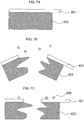
- the conventional method of applying a mechanical force for the trimming as shown in FIG. 7A through FIG. 7C , foreign object particles 409 are generated when a substrate 405 is cut, and are attached to a pellicle film 401 or a pellicle frame 402.
- the foreign object particles 109 are captured by the pressure-sensitive adhesive sheets 106 and 107, and thus are suppressed from being attached to the pellicle film 101.
- the substrate may be trimmed by blade dicing or laser ablation.
- these methods do not avoid generation of foreign object particles 509 while the substrate 505 is cut.
- the foreign object particles 509 are attached to a pellicle film 501 or a pellicle frame 502, and thus the pellicle is contaminated.
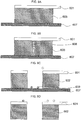
- the above-described stealth dicing may be used.
- this method no notch is made in the surface of the pellicle, which is a processing target. Therefore, on the stage of forming a quality-modified region inside the substrate, no foreign object particle is generated.
- foreign object particles 609 scatter as dust on the stage of expanding (pulling) a substrate 605 and a pressure-sensitive adhesive sheet 607 using the quality-modified region as a start point. Therefore, even with the stealth dicing, the foreign object particles 609 are attached to a pellicle film 601 or a pellicle frame 602, and thus the pellicle is contaminated.
- a path through which the foreign object particles scatter outside is blocked by the pressure-sensitive adhesive sheets 106 and 107 more than by the above-described other trimming methods. Therefore, the foreign object particles 109 are suppressed from being attached to the pellicle film 101 or the pellicle frame 102.
- Described in embodiment 2 is a method for bonding pressure-sensitive adhesive sheets in the case where a portion of the substrate that is to be a pellicle frame and the substrate outer peripheral portion have, therebetween, an opening formed in advance and are coupled with each other via a bridge portion.
- a notch for the trimming merely needs to be made in the bridge portion.
- FIG. 5A and FIG. 5B are plan views showing positions at which pressure-sensitive adhesive sheets are bonded in embodiment 2 according to the present invention.
- FIG. 5A shows a state with no pressure-sensitive adhesive sheet 206.
- FIG. 5B shows a state where the pressure-sensitive adhesive sheets 206 are bonded.
- FIG. 5C is a cross-sectional view taken along line C-C in FIG. 5B .
- a bridge portions 210 is connected to each of four corners of a pellicle frame 202. Openings 212 are provided between the pellicle frame 202 and the substrate outer peripheral portion 211, and the pellicle frame 202 and a substrate outer peripheral portion 211 are coupled with each other via the bridge portions 210.
- Pressure-sensitive adhesive sheets 206 and 207 are bonded to cover both of two surfaces and both two side surfaces of each of the bridge portions 210.
- the pressure-sensitive adhesive sheets may be bonded along the openings over the bridge portions, or as shown in FIG. 5D , a pressure-sensitive adhesive sheet 207A may be bonded such that a pressure-sensitive adhesive thereof fills each opening.
- one pressure-sensitive adhesive sheet 206 covers two bridge portions 210.
- a notch is made inside each of the bridge portions at the four corners.
- the notch is made along a direction perpendicular to the direction in which the bridge portion 210 extends (e.g., the notch is made in the direction of line C-C).
- the pressure-sensitive adhesive sheet 207 or 207A and the bridge portions 210 are expanded to separate the bridge portions, so that the pellicle frame is formed.
- the pressure-sensitive adhesive sheets 206 and 207 (or 207A) are irradiated with ultraviolet light to be peeled off. Thus, the trimming is finished.
- the structure of the substrate is the same as that in embodiment 2.
- the pressure-sensitive adhesive sheets are bonded in a different manner.
- FIG. 6A is a plan view showing positions at which pressure-sensitive adhesive sheets are bonded in embodiment 3 according to the present invention.
- FIG. 6B is a cross-sectional view taken long line D-D in FIG. 6A .
- pressure-sensitive adhesive sheets 306 and 307 are bonded to cover both of two surfaces and both two side surfaces of each of the bridge portions 210.
- one pressure-sensitive adhesive sheet 306 and one pressure-sensitive adhesive sheet 307 cover each of the bridge portions 210.
- the pressure-sensitive adhesive sheets may be bonded along openings 212 over the bridge portions 210, or as shown in FIG. 6C , a pressure-sensitive adhesive sheet 307A may be bonded such that a pressure-sensitive adhesive thereof fills each opening 212.
- the method for separation and the like are substantially the same as those in embodiment 2 and will not be described here.
Landscapes
- Physics & Mathematics (AREA)
- General Physics & Mathematics (AREA)
- Engineering & Computer Science (AREA)
- Optics & Photonics (AREA)
- Chemical & Material Sciences (AREA)
- Plasma & Fusion (AREA)
- Mechanical Engineering (AREA)
- Organic Chemistry (AREA)
- Chemical Kinetics & Catalysis (AREA)
- General Chemical & Material Sciences (AREA)
- Oil, Petroleum & Natural Gas (AREA)
- Preparing Plates And Mask In Photomechanical Process (AREA)
Applications Claiming Priority (2)
| Application Number | Priority Date | Filing Date | Title |
|---|---|---|---|
| JP2015090780 | 2015-04-27 | ||
| PCT/JP2016/061730 WO2016175019A1 (ja) | 2015-04-27 | 2016-04-11 | ペリクルの製造方法およびペリクル付フォトマスクの製造方法 |
Publications (2)
| Publication Number | Publication Date |
|---|---|
| EP3291006A1 true EP3291006A1 (de) | 2018-03-07 |
| EP3291006A4 EP3291006A4 (de) | 2019-01-23 |
Family
ID=57199078
Family Applications (1)
| Application Number | Title | Priority Date | Filing Date |
|---|---|---|---|
| EP16786296.0A Withdrawn EP3291006A4 (de) | 2015-04-27 | 2016-04-11 | Pellikelherstellungsverfahren und verfahren zur herstellung einer photomaske mit pellikel |
Country Status (8)
| Country | Link |
|---|---|
| US (1) | US10895805B2 (de) |
| EP (1) | EP3291006A4 (de) |
| JP (1) | JP6371904B2 (de) |
| KR (1) | KR102060869B1 (de) |
| CN (1) | CN107533283B (de) |
| SG (1) | SG11201708585SA (de) |
| TW (1) | TWI718143B (de) |
| WO (1) | WO2016175019A1 (de) |
Cited By (1)
| Publication number | Priority date | Publication date | Assignee | Title |
|---|---|---|---|---|
| EP3365730A2 (de) * | 2015-10-22 | 2018-08-29 | ASML Netherlands B.V. | Verfahren zur herstellung eines pellikels für eine lithographische vorrichtung, pellikel für eine lithographische vorrichtung, lithographische vorrichtung, verfahren zur herstellung der vorrichtung, vorrichtung zur bearbeitung eines pellikels und verfahren zur bearbeitung eines pellikels |
Families Citing this family (9)
| Publication number | Priority date | Publication date | Assignee | Title |
|---|---|---|---|---|
| WO2016043301A1 (ja) * | 2014-09-19 | 2016-03-24 | 三井化学株式会社 | ペリクル、ペリクルの製造方法及びペリクルを用いた露光方法 |
| CN106662806B (zh) * | 2014-09-19 | 2021-11-05 | 三井化学株式会社 | 防护膜组件、其制造方法及曝光方法 |
| JP6844443B2 (ja) * | 2017-06-23 | 2021-03-17 | 信越化学工業株式会社 | フォトリソグラフィ用ペリクル膜、ペリクル及びフォトマスク、露光方法並びに半導体デバイス又は液晶ディスプレイの製造方法 |
| KR102459119B1 (ko) * | 2018-06-12 | 2022-10-26 | 미쯔이가가꾸가부시끼가이샤 | 펠리클용 지지 프레임, 펠리클 및 펠리클용 지지 프레임의 제조 방법, 그리고 펠리클을 사용한 노광 원판 및 노광 장치 |
| TWI670562B (zh) * | 2018-06-21 | 2019-09-01 | 美商微相科技股份有限公司 | 光罩保護組件結構 |
| KR102446173B1 (ko) * | 2018-06-26 | 2022-09-22 | 삼성전자주식회사 | 펠리클용 접착제, 포토 마스크용 펠리클 및 그 제조 방법 |
| KR102727055B1 (ko) | 2018-11-20 | 2024-11-06 | 삼성전자주식회사 | 극자외선 리소그래피용 펠리클 및 그 제조방법 |
| US20240192586A1 (en) | 2021-04-13 | 2024-06-13 | Shin-Etsu Chemical Co., Ltd. | Pellicle Frame Laminate and Method for Manufacturing Pellicle Using Said Laminate |
| KR102705080B1 (ko) * | 2021-04-14 | 2024-09-11 | 한국전자기술연구원 | 극자외선 노광용 펠리클 |
Family Cites Families (13)
| Publication number | Priority date | Publication date | Assignee | Title |
|---|---|---|---|---|
| JPH05109889A (ja) * | 1991-04-24 | 1993-04-30 | Nikko Kyodo Co Ltd | ウエハの分割方法 |
| US5793836A (en) * | 1996-09-06 | 1998-08-11 | International Business Machines Corporation | X-ray mask pellicle |
| US5814381A (en) * | 1997-04-04 | 1998-09-29 | Inko Industrial Corporation | Pellicle assembly having a vented frame |
| JP2000292909A (ja) * | 1999-04-09 | 2000-10-20 | Shin Etsu Chem Co Ltd | ペリクルおよびペリクルの製造方法 |
| US6593035B1 (en) * | 2001-01-26 | 2003-07-15 | Advanced Micro Devices, Inc. | Pellicle for use in small wavelength lithography and a method for making such a pellicle using polymer films |
| JP4777761B2 (ja) * | 2005-12-02 | 2011-09-21 | 株式会社ディスコ | ウエーハの分割方法 |
| JP2011076042A (ja) | 2009-10-02 | 2011-04-14 | Shin-Etsu Chemical Co Ltd | ペリクル |
| JP5152870B2 (ja) | 2009-12-07 | 2013-02-27 | 信越化学工業株式会社 | リソグラフィ用ペリクル及びその製造方法 |
| JP5552095B2 (ja) | 2011-06-21 | 2014-07-16 | 信越化学工業株式会社 | Euv用レチクル |
| JP5517360B2 (ja) | 2011-07-05 | 2014-06-11 | 信越化学工業株式会社 | ペリクル及びその製造方法 |
| JP2013057861A (ja) | 2011-09-09 | 2013-03-28 | Shin Etsu Chem Co Ltd | リソグラフィ用ペリクルおよびその製造方法 |
| US8586267B2 (en) * | 2011-09-12 | 2013-11-19 | Samsung Austin Semiconductor, L.P. | Removable transparent membrane for a pellicle |
| EP3007206A4 (de) | 2013-05-24 | 2017-03-15 | Mitsui Chemicals, Inc. | Pellikula und euv-belichtungsvorrichtung damit |
-
2016
- 2016-04-11 EP EP16786296.0A patent/EP3291006A4/de not_active Withdrawn
- 2016-04-11 JP JP2017515466A patent/JP6371904B2/ja active Active
- 2016-04-11 WO PCT/JP2016/061730 patent/WO2016175019A1/ja not_active Ceased
- 2016-04-11 KR KR1020177029789A patent/KR102060869B1/ko active Active
- 2016-04-11 CN CN201680023233.0A patent/CN107533283B/zh active Active
- 2016-04-11 SG SG11201708585SA patent/SG11201708585SA/en unknown
- 2016-04-19 TW TW105112087A patent/TWI718143B/zh active
-
2017
- 2017-10-26 US US15/794,420 patent/US10895805B2/en active Active
Cited By (3)
| Publication number | Priority date | Publication date | Assignee | Title |
|---|---|---|---|---|
| EP3365730A2 (de) * | 2015-10-22 | 2018-08-29 | ASML Netherlands B.V. | Verfahren zur herstellung eines pellikels für eine lithographische vorrichtung, pellikel für eine lithographische vorrichtung, lithographische vorrichtung, verfahren zur herstellung der vorrichtung, vorrichtung zur bearbeitung eines pellikels und verfahren zur bearbeitung eines pellikels |
| US12298663B2 (en) | 2015-10-22 | 2025-05-13 | Asml Netherlands B.V. | Method of manufacturing a pellicle for a lithographic apparatus, a pellicle for a lithographic apparatus, a lithographic apparatus, a device manufacturing method, an apparatus for processing a pellicle, and a method for processing a pellicle |
| EP3365730B1 (de) * | 2015-10-22 | 2025-07-16 | ASML Netherlands B.V. | Verfahren zur herstellung eines pellikels für eine lithographische vorrichtung und pellikel für eine lithographische vorrichtung |
Also Published As
| Publication number | Publication date |
|---|---|
| US10895805B2 (en) | 2021-01-19 |
| TWI718143B (zh) | 2021-02-11 |
| TW201704852A (zh) | 2017-02-01 |
| KR102060869B1 (ko) | 2019-12-30 |
| SG11201708585SA (en) | 2017-11-29 |
| CN107533283B (zh) | 2021-05-28 |
| US20180046071A1 (en) | 2018-02-15 |
| JPWO2016175019A1 (ja) | 2018-02-15 |
| JP6371904B2 (ja) | 2018-08-08 |
| WO2016175019A1 (ja) | 2016-11-03 |
| KR20170128546A (ko) | 2017-11-22 |
| CN107533283A (zh) | 2018-01-02 |
| EP3291006A4 (de) | 2019-01-23 |
Similar Documents
| Publication | Publication Date | Title |
|---|---|---|
| US10895805B2 (en) | Pellicle manufacturing method and method for manufacturing photomask with pellicle | |
| JP4934099B2 (ja) | ペリクルおよびペリクルの製造方法 | |
| EP3477387B1 (de) | Pellikelfolie, pellikelrahmenkörper, pellikel und verfahren zur pellikelherstellung | |
| JP6367342B2 (ja) | ペリクル、ペリクルの製造方法及びペリクルを用いた露光方法 | |
| EP3671343A1 (de) | Pellikelfilm für photolithographie und damit versehener pellikel | |
| TWI398723B (zh) | 防護薄膜組件及其製造方法 | |
| EP2051139B1 (de) | Pellikel und Verfahren zu dessen Herstellung | |
| EP3264175B1 (de) | Verfahren zur herstellung eines membranfilms | |
| KR102015437B1 (ko) | 극자외선 리소그래피용 펠리클 및 그의 제조 방법 | |
| CN102405440A (zh) | 光刻用防尘薄膜组件及其制造方法 | |
| JP2016130789A (ja) | Euvマスク用ペリクル | |
| CN113196168A (zh) | 制造隔膜组件的方法 | |
| JP2005003564A (ja) | 電子ビーム管および電子ビーム取り出し用窓 | |
| EP3506010B1 (de) | Pellikelherstellungsverfahren | |
| TW518659B (en) | Method for manufacturing a membrane mask | |
| US12346022B2 (en) | Method of fabricating pellicle structure | |
| JP2004311839A (ja) | マスクブランクスの作製方法 | |
| JP2008186995A (ja) | 露光用マスクブランクス、露光用マスクおよびそれらの製造方法 | |
| CN106206265A (zh) | 半导体装置及其形成方法 | |
| JPH05275319A (ja) | X線リソグラフィマスクの製造方法およびx線リソグラフィマスク | |
| HK1097053B (en) | Pellicle frame | |
| JP2001316187A (ja) | 炭化珪素とシリコンの接合方法 | |
| HK1097053A1 (en) | Pellicle frame | |
| JP2004214551A (ja) | X線マスクの製造方法およびその方法により製造されるx線マスク |
Legal Events
| Date | Code | Title | Description |
|---|---|---|---|
| STAA | Information on the status of an ep patent application or granted ep patent |
Free format text: STATUS: THE INTERNATIONAL PUBLICATION HAS BEEN MADE |
|
| PUAI | Public reference made under article 153(3) epc to a published international application that has entered the european phase |
Free format text: ORIGINAL CODE: 0009012 |
|
| STAA | Information on the status of an ep patent application or granted ep patent |
Free format text: STATUS: REQUEST FOR EXAMINATION WAS MADE |
|
| 17P | Request for examination filed |
Effective date: 20171110 |
|
| AK | Designated contracting states |
Kind code of ref document: A1 Designated state(s): AL AT BE BG CH CY CZ DE DK EE ES FI FR GB GR HR HU IE IS IT LI LT LU LV MC MK MT NL NO PL PT RO RS SE SI SK SM TR |
|
| AX | Request for extension of the european patent |
Extension state: BA ME |
|
| DAV | Request for validation of the european patent (deleted) | ||
| DAX | Request for extension of the european patent (deleted) | ||
| A4 | Supplementary search report drawn up and despatched |
Effective date: 20190103 |
|
| RIC1 | Information provided on ipc code assigned before grant |
Ipc: G03F 1/62 20120101AFI20181219BHEP Ipc: B23K 26/53 20140101ALI20181219BHEP Ipc: G03F 1/24 20120101ALI20181219BHEP |
|
| RAP1 | Party data changed (applicant data changed or rights of an application transferred) |
Owner name: TAZMO CO., LTD. Owner name: MITSUI CHEMICALS, INC. |
|
| STAA | Information on the status of an ep patent application or granted ep patent |
Free format text: STATUS: EXAMINATION IS IN PROGRESS |
|
| 17Q | First examination report despatched |
Effective date: 20220125 |
|
| GRAP | Despatch of communication of intention to grant a patent |
Free format text: ORIGINAL CODE: EPIDOSNIGR1 |
|
| STAA | Information on the status of an ep patent application or granted ep patent |
Free format text: STATUS: GRANT OF PATENT IS INTENDED |
|
| RIC1 | Information provided on ipc code assigned before grant |
Ipc: C09J 7/38 20180101ALI20220609BHEP Ipc: B23K 101/40 20060101ALI20220609BHEP Ipc: B23K 103/00 20060101ALI20220609BHEP Ipc: B23K 26/00 20140101ALI20220609BHEP Ipc: B23K 26/53 20140101ALI20220609BHEP Ipc: G03F 1/24 20120101ALI20220609BHEP Ipc: G03F 1/62 20120101AFI20220609BHEP |
|
| INTG | Intention to grant announced |
Effective date: 20220630 |
|
| RAP3 | Party data changed (applicant data changed or rights of an application transferred) |
Owner name: TAZMO CO., LTD. Owner name: MITSUI CHEMICALS, INC. |
|
| RIN1 | Information on inventor provided before grant (corrected) |
Inventor name: HIROTA, TOSHIAKI Inventor name: SATO, YASUYUKI Inventor name: BIYAJIMA, TSUNEAKI Inventor name: ISHIKAWA, HISAKO Inventor name: ONO, YOSUKE Inventor name: TANEICHI, DAIKI Inventor name: KOHMURA, KAZUO |
|
| STAA | Information on the status of an ep patent application or granted ep patent |
Free format text: STATUS: THE APPLICATION IS DEEMED TO BE WITHDRAWN |
|
| 18D | Application deemed to be withdrawn |
Effective date: 20221111 |