EP3291278A1 - Magnétron - Google Patents
Magnétron Download PDFInfo
- Publication number
- EP3291278A1 EP3291278A1 EP16786094.9A EP16786094A EP3291278A1 EP 3291278 A1 EP3291278 A1 EP 3291278A1 EP 16786094 A EP16786094 A EP 16786094A EP 3291278 A1 EP3291278 A1 EP 3291278A1
- Authority
- EP
- European Patent Office
- Prior art keywords
- cooling block
- fastener
- pipe joints
- magnetron
- anode cylinder
- Prior art date
- Legal status (The legal status is an assumption and is not a legal conclusion. Google has not performed a legal analysis and makes no representation as to the accuracy of the status listed.)
- Granted
Links
Images



Classifications
-
- H—ELECTRICITY
- H01—ELECTRIC ELEMENTS
- H01J—ELECTRIC DISCHARGE TUBES OR DISCHARGE LAMPS
- H01J23/00—Details of transit-time tubes of the types covered by group H01J25/00
-
- H—ELECTRICITY
- H01—ELECTRIC ELEMENTS
- H01J—ELECTRIC DISCHARGE TUBES OR DISCHARGE LAMPS
- H01J25/00—Transit-time tubes, e.g. klystrons, travelling-wave tubes, magnetrons
- H01J25/50—Magnetrons, i.e. tubes with a magnet system producing an H-field crossing the E-field
- H01J25/52—Magnetrons, i.e. tubes with a magnet system producing an H-field crossing the E-field with an electron space having a shape that does not prevent any electron from moving completely around the cathode or guide electrode
- H01J25/58—Magnetrons, i.e. tubes with a magnet system producing an H-field crossing the E-field with an electron space having a shape that does not prevent any electron from moving completely around the cathode or guide electrode having a number of resonators; having a composite resonator, e.g. a helix
- H01J25/587—Multi-cavity magnetrons
-
- H—ELECTRICITY
- H01—ELECTRIC ELEMENTS
- H01J—ELECTRIC DISCHARGE TUBES OR DISCHARGE LAMPS
- H01J23/00—Details of transit-time tubes of the types covered by group H01J25/00
- H01J23/005—Cooling methods or arrangements
Definitions
- the present disclosure relates to magnetrons that generate microwaves.
- Magnetrons that generate microwaves have been employed in magnetron utilization equipment, such as microwave ovens, and are available in various structures. To remove heat generated by magnetrons, in line with generation of microwaves, an air cooling system and liquid cooling system have been employed. Magnetrons adopting the liquid cooling system use a cooling block with a circulation passage for cooling liquid (e.g., PTL1).
- FIG. 9 showing the entire structure of the magnetron
- Fig. 10 showing a structure of the cooling block.
- cooling block 110 provided in magnetron 100 is closely attached along an outer peripheral face of an anode cylinder (not illustrated) in yoke 106.
- Cooling block 110 has a circulation passage 112 inside for passing liquid for cooling the anode cylinder.
- cooling block 110 is made of a material having a cooling function and formed in an approximately rectangular-parallelepiped shape.
- Inlet pipe joint 112A and outlet pipe joint 112B communicated with circulation passage 112 are connected to one side face of rectangular parallelepiped cooling block 110.
- Cooling block 110 includes an annular continuous part around the outer peripheral face of the anode cylinder, and a discontinuous part where both ends of the annular continuous part face each other. More specifically, flange 114 is formed at each end of the annular continuous part and an annular discontinuous part is located between mutually-facing flanges 114.
- Each flange 114 has through hole 115, and fastener 116 communicates with opposing through holes 115 and is screwed. This narrows a distance between flanges 14 and an inner peripheral face of cooling block 110 is tightened to closely attach to an outer peripheral face of the anode cylinder.
- Cooling block 110 in above conventional magnetron 100 is formed as an integral component with desired shape by cutting a substantially rectangular-parallelepiped material.
- flange 114 is formed at both ends of the annular continuous part for fastening cooling block 110. Flanges 114 are larger than the connecting faces of pipe joints 112A and 112, and protruding outward.
- fastener 116 In the state pipe joints 112A and 112B are connected to cooling block 110, it may be difficult to insert fastener 116 into through holes 115 in flanges 114. It may also become difficult to gain access to fastener 116 in the state engaged with flanges 114.
- an object of the present disclosure is to solve the above disadvantages, and offer a magnetron that can reduce wasted material in fabricating the cooling block, and ensure a good access to the pipe joint and fastener.
- a magnetron in an exemplary embodiment of the present disclosure includes an anode cylinder, a cooling block, a fastener, and a pair of pipe joints.
- the cooling block is an integral component having an annular shape in which both ends of an annular continuous part face each other.
- the cooling block is fastened on an outer peripheral face of the anode cylinder to surround the anode cylinder.
- the cooling block has a cooling liquid circulation passage inside, so as to cool the anode cylinder.
- the fastener is engaged with both ends of the cooling block facing each other.
- An inner peripheral face of the cooling block is pushed toward the outer peripheral face of the anode cylinder by tightening the fastener to narrow a distance between both ends.
- a pair of pipe joints are provided on the outer peripheral face of the cooling block, so as to communicate with the circulation passage.
- the fastener is disposed between the pair of pipe joints, and a discontinuous part between both ends of the cooling block facing each other extends in a tilted manner in the annular direction of the cooling block relative to the flow direction of the cooling liquid at a connecting part of the pair of pipe joints and circulation passage.
- the fastener passing the discontinuous part extends in a direction tilted in a face perpendicular to the flow direction of the cooling liquid at the connecting part of the pair of pipe joints and circulation passage.
- the exemplary embodiment can offer a magnetron that can reduce wasteful material in fabrication of the cooling block, and also secure a good access to the pipe joints and fastener.
- a magnetron in a first embodiment includes an anode cylinder, a cooling block, a fastener, and a pair of pipe joints.
- the cooling block is an integral component having an annular shape with both ends of an annular continuous part facing each other.
- the cooling block is fastened on an outer peripheral face of the anode cylinder such that the cooling block surrounds the anode cylinder.
- the cooling block also has a cooling liquid circulation passage inside, so as to cool the anode cylinder.
- the fastener is engaged with both ends of the cooling block facing each other, and pushes an inner peripheral face of the cooling block toward the outer peripheral face of the anode cylinder by tightening and narrowing a distance between both ends.
- the pair of pipe joints are provided on the outer peripheral face of the cooling block to communicate with the circulation passage.
- the fastener is disposed between the pair of pipe joints, and a discontinuous part between both ends of the cooling block facing each other extends in a tilted manner in the annular direction of the cooling block relative to the flow direction of the cooling liquid at a connecting part of the pair of pipe joints and circulation passage.
- the fastener passing the discontinuous part extends in a direction tilted relative to a face perpendicular to the flow direction of the cooling liquid at the connecting part of the pair of pipe joints and circulation passage.
- the discontinuous part and fastener in the cooling block are disposed in a tilted manner so that interference of these components can be suppressed at gaining access to the pipe joints and the fastener. Accordingly, a good access to the pipe joints and the fastener is secured.
- the pipe joints and fastener can be disposed in a layout that can reduce a cut and wasted part on cutting out the cooling block.
- a recess is formed between a pair of pipe joints in the first embodiment, and at least a part of the fastener is disposed in the recess.
- one end of the fastener is disposed in the recess in the first or second embodiment.
- This layout enables to place the fastener without being protruded from the outer peripheral face of the cooling block. An interference with the fastener at particularly gaining access to the pipe joints can be suppressed. Accordingly, a good access to the pipe joints and fastener can be secured.
- the fastener extends in a direction perpendicular to the discontinuous part in one of the first to third embodiments.
- the embodiment enables to further uniformly tighten the cooling block and the anode cylinder, and thus further reliable tightening becomes feasible.
- the discontinuous part extends along a radial direction of the anode cylinder disposed in the cooling block in one of the first to fourth embodiments.
- the embodiment enables to further uniformly tighten the cooling block and the anode cylinder, and thus further reliable tightening becomes feasible.
- the cooling block has substantially a rectangle outer periphery, and a connecting face is provided on one end of the outer periphery in one of the first to fifth embodiments.
- This embodiment can reduce wasted material in cutting out the cooling block, and also secure a good access to the pipe joints and fastener while adopting a centralized layout of disposing the pipe joints and fastener on one end in the outer periphery.
- a connecting face of the cooling block to which one of the pair of pipe joints is connected is provided on substantially the same plane as a connecting face of the cooling block to which the other of the pair of pipe joints is connected in one of the first to sixth embodiments.
- the embodiment facilitates fabrication of the cooling block.
- the fastener extends in a direction parallel to a plane including the annular direction of the cooling block in one of the first to seventh embodiments.
- the embodiment enables to further reliably tighten the cooling block and anode cylinder, compared to a case of extending the fastener in a direction tilted relative to a plane including the annular direction of the cooling block.
- the fastener extends in a direction tilted relative to a plane including the annular direction of the cooling block in one of the first to eighth embodiments.
- the embodiment enables to reduce an area of the recess in the connecting face of the cooling block, compared to a case of extending the fastener in the plane including the annular direction of the cooling block. Accordingly, the embodiment can improve the tightening strength of the cooling block and anode cylinder at the connecting face.
- Fig. 1 is an overall structure of magnetron 1 in the exemplary embodiment of the present disclosure
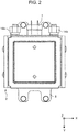
- Fig. 2 is a bottom view of magnetron 1.
- magnetron 1 includes magnetic yoke 2, output unit 3 provided above magnetic yoke 2, and filter 4 provided below magnetic yoke 2.
- Magnetic yoke 2 houses anode cylinder 5, two annular permanent magnets 6A and 6B provided on top and bottom ends of anode cylinder 5, and cooling block 10 disposed around anode cylinder 5.
- Filter 4 includes choke coil (not illustrated) and feedthrough capacitor 7.
- the vertical direction (axial direction of anode cylinder 5) is the Z direction, and directions orthogonal to the Z direction and also orthogonal to each other are the X direction and Y direction.
- the X direction is the right and left direction
- the Y direction is the front and back direction
- the Z direction is the top and bottom direction.
- directions are not particularly limited.
- Magnetron 1 in the exemplary embodiment gives an example of setting the Z direction (top and bottom direction) to the axial direction of anode cylinder 5.
- the axial direction of anode cylinder 5 may be the left and right direction or the front and back direction.
- Magnetic yoke 2 includes main body 8a whose pair of opposing side faces and a top face are open, and cover 8b that closes an opening on the top face of main body 8a.
- Annular permanent magnets 6A and 6B, anode cylinder 5, and cooling block 10 are housed in casing 8 of magnetic yoke 2.
- Anode cylinder 5 is fixed with casing 8 of magnetic yoke 2 such that it is externally sandwiched by annular permanent magnets 6A and 6B disposed on both vertical ends.
- Annular permanent magnet 6B disposed at the bottom in Fig. 1 is an input magnet
- annular permanent magnet 6A disposed on the top is an output magnet.
- Anode vanes (not illustrated) inside anode cylinder 5 are radially disposed.
- a space surrounded by adjacent anode vanes and anode cylinder 5 forms a cavity resonator.
- a cathode structure (not illustrated) is disposed at the center of anode cylinder 5.
- a space surrounded by this cathode structure and anode vanes is an interaction space.
- magnetron 1 in the exemplary embodiment When magnetron 1 in the exemplary embodiment is used, required power is applied to the cathode structure to emit thermoelectrons after inside magnetron 1 is vacuumed, and DC high voltage is applied between the anode vanes and cathode structure.
- annular permanent magnets 6A and 6B form a magnetic field in a direction orthogonal to a direction that the cathode structure and anode cylinder 5 face each other.
- Electrons turn and circulate by the electric field and magnetic field in the interaction space, and reach the anode vanes.
- energy produced by electron motion is given to the cavity resonator to emit microwaves.
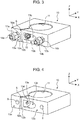
- FIG. 3 is a perspective view of cooling block 10
- Fig. 4 is a perspective view of cooling block 10 in which a pipe joint and fastener for connecting a cooling liquid pipe are removed.
- Fig. 5 is a lateral sectional view (XY plane) inside cooling block 10 in Fig. 3 .
- Cooling block 10 has a function of cooling anode cylinder 5 and annular permanent magnets 6A and 6B by making direct or indirect contact with these components. More specifically, as shown in Fig. 3 and Fig. 4 , cooling block 10 has a substantially rectangular-parallelepiped outer shape, and is integrally formed with, for example, a metal material with high heat conductivity (e.g., copper and aluminum). Circulation passage 9 for passing cooling liquid is formed inside cooling block 10.
- Cooling block 10 includes an annular continuous part around an outer peripheral face of anode cylinder 5, and has an annular shape in which both ends of this annular continuous part face each other in a close distance.
- annular discontinuous part exists only on a part of cooling block 10 when seen from the top (in the Z direction) in Fig. 3 .
- Inner peripheral face 11 of cooling block 10 is formed as an inner peripheral face attachable to an outer peripheral face of anode cylinder 5.
- the outer periphery of cooling block 10 is formed substantially rectangle to be fitted in casing 8 of magnetic yoke 2.
- Cooling block 10 makes indirect contact with annular permanent magnet 6A near inner peripheral face 11 on the top face of cooling block 10 via other components, and makes indirect contact with annular permanent magnet 6B near inner peripheral face 11 on the bottom face of cooling block 10 via other components.
- both ends of the annular continuous part of cooling block are referred to as opposing ends 12a and 12b.
- a pair of pipe joints 14a and 14b for supply and discharge that communicate with circulation passage 9 are connected to connecting faces 13a and 13b where opposing ends 12a and 12b are disposed on the substantially rectangle outer periphery of cooling block 10.
- Pipe joint 14a is connected to connecting face 13a including opposing end 12a
- pipe joint 14b is connected to connecting face 13b including opposing end 12b.
- Pipe joints 14a and 14b include anchoring bolt 16a and anchoring bolt 16b, connecting nut 17a and connecting nut 17b for detachably connecting a supply pipe/discharge pipe of the cooling liquid, respectively.
- Circulation passage 9 in cooling block 10 is formed from a connecting part of pipe joint 14a to a connecting part of pipe joint 14b via the outer periphery of anode cylinder 5.
- Opposing ends 12a and 12b are disposed on connecting faces 13a and 13b, respectively, and space S is provided between opposing ends 12a and 12b.
- This space S between opposing ends 12a and 12b is the annular discontinuous part, and is formed from inner peripheral face 11 of cooling block 10 to the outer peripheral face of cooling block 10.
- connecting faces 13a and 13b are provided on substantially the same plane across space S.
- connecting face 13a to which pipe joint 14a is connected and connecting face 13b to which pipe joint 14b is connected are provided on substantially the same plane.
- Fastener 15 (e.g., anchoring bolt and nut) is engaged with each of opposing ends 12a and 12b, and fastener 15 is disposed in recess 13c in connecting face 13b. By tightening fastener 15 with screw, space S (distance) between opposing ends 12a and 12b can be narrowed.
- space S is set to, for example, about 3 mm before being tightened.
- fastener 15 extends in a direction parallel to a plane (XY plane) including the annular direction (a turning direction of anode cylinder 5) of cooling block 10.
- Recess 13c opened to the side is formed in connecting face 13b connected to pipe joint 14b.
- Fastener 15 is inserted inside recess 13c, and engagement hole 13d and engagement hole 13e that engage with inserted fastener 15 are formed in an inner face of recess 13C (see Fig. 4 ). In a state that fastener 15 is inserted to and engaged with both engagement holes 13d and 13e ( Fig. 3 ), fastener 15 is housed inside recess 13c.
- YZ plane passing center C of anode cylinder 5 and perpendicular to connecting faces 13a and 13b is plane 18.
- the Y direction that is the flow direction of the cooling liquid at a connecting part (connecting faces 13a and 13b) of pair of pipe joints 14a and 14b and circulation passage 9 exists in plane 18.
- the flow direction of cooling liquid matches the connecting direction of pipe joints 14a and 14b to cooling block 10, the connecting direction of pipes (not illustrated) to pipe joints 14a and 14b, the pipe axial direction of pipe joints 14a and 14b, and the front and back direction of cooling block 10 in the exemplary embodiment.
- Space S in cooling block 10 extends in a direction tilted relative to plane 18 perpendicular to connecting faces 13a and 13b. More specifically, the direction that space S extends in the exemplary embodiment is tilted by 30° relative to plane 18 in a plan view.
- space S is tilted by 30° in the annular direction of cooling block 10 relative to the flow direction (Y direction) of the cooling liquid at the connecting part of pair of pipe joints 14a and 14b and circulation passage 9 (i.e., tilted by 30 ° in the XY plane).
- a tilt angle of space S is not limited.
- space S extends in a direction passing center C of anode cylinder 5, and crosses plane 18 at center C. With this layout, space S extends in the normal direction (i.e., radial direction of cooling block 10) perpendicular to the tangential direction of inner peripheral face 11 of cooling block 10.
- fastener 15 is disposed inside recess 13c in cooling block 10 such that fastener 15 extends in a direction perpendicular to this space S.
- fastener 15 passing space S extends in a direction tiled relative to a face perpendicular to the flow direction of the cooling liquid at the connecting part of pair of pipe joints 14a and 14b and circulation passage 9 (XZ plane).
- the tilt angle is set to 30°.
- a space for placing fastener 15 in cooling block 10 ends at a position not reaching circulation passage 9 to avoid interference with circulation passage 9.
- One end (bolt head) of fastener 15 disposed in this space is placed in recess 13c so that it does not protrude to the XZ plane where connecting faces 13a and 13b are provided.
- fastener 15 When fastener 15 is disposed in recess 13c in cooling block 10 and tightened, space S is narrowed. This fastens the inner peripheral face 11 of cooling block 10 onto anode cylinder 5 to anchor anode cylinder 5. In this tightening operation, fastener 15 is simply inserted into recess 13c and turned, and thus the operation can be implemented without interfering with pipe joints 14a and 14b.
- a component for closing the fastener such as a nut, can be omitted. This has an advantage of reducing manufacturing cost.
- an area of connecting faces 13a and 13b that have a function to retain the tightening strength on tightening can be secured. This can achieve a predetermined tightening strength.
- space S extends in the radial direction of anode cylinder 5 in cooling block 10.
- Fastener 15 is disposed in a direction perpendicular to space S (and its extending plane). This layout enables to further uniformly tighten cooling block 10 and anode cylinder 5 with fastener 15. Cooling block 10 and anode cylinder 5 can thus be fixed in a further stable state.
- fastener 15 extends in a direction parallel to a plane (XY plane) including the annular direction of cooling block 10 (turning direction of anode cylinder 5). This enables to further uniformly and stably tighten cooling block 10 and anode cylinder 5 in good balance, compared to the case of tilting fastener 15 relative to the XY plane.
- connecting faces 13a and 13b are provided on substantially the same plane across space S. This structure facilitates fabrication of cooling block 10. Cooling block 10 and anode cylinder 5 can be stably fixed in a good balance also when fastener 15 is tightened to narrow space S.
- substantially the same plane includes cases when relative positions of opposing ends 12a and 12b are deviated due to tightening of fastener 15, in addition to the case when connecting faces 13a and 13b are on the same plane.
- space S and fastener 5 are disposed in a tilted manner, in addition to pipe joints 14a and 14b and fastener 15 disposed on connecting faces 13a and 13b. This reduces an influence of pipe joints 14a and 14b at gaining access to fastener 15 even though a structure of disposing fastener 15 between pair of pipe joints 4a and 14b is adopted.
- fastener 15 can be used and tightened in the state pair of pipe joints 14a and 14b are connected to cooling block 10 and the cooling liquid pipe is also connected.
- connecting faces 13a and 13b for connecting pipe joints 14a and 14b in cooling block 10 can be more flexibly disposed.
- cooling block 10 when forming cooling block 10 by cutting out a substantially rectangular-parallelepiped material, for example, pipe joints 14a and 14b and fastener 15 can be disposed in a layout that can reduce shaved material, compared to the conventional cooling block shown in Fig. 9 and Fig. 10 .
- cooling block 10 Accordingly, wasted material in fabrication of cooling block 10 can be reduced, and also a good access to pipe joints 14a and 14b and fastener 15 can be secured. Less portion to cut can increase the volume of cooling block 10, and thus cooling performance can be improved.
- the present disclosure is described with reference to the above exemplary embodiment. However, the present disclosure is not limited to the aforementioned exemplary embodiment.
- the above exemplary embodiment refers to the case of leaving a space without completely closing space S when fastener 15 is tightened. However, the present disclosure is not limited to this structure. Opposing ends 12a and 12b may also mutually contact.
- the above exemplary embodiment refers to the case of placing one end of fastener 15 in recess 13c, and this one end does not cross the XZ plane where connecting faces 13a and 13b are provided.
- the present disclosure is not limited to this structure, as long as at least a part of fastener 15 is placed in recess 13c.
- Fastener 15 can be placed without being protruded, in particular, from the outer peripheral face of cooling block 10 when one end of fastener 15 is placed in recess 13, as in the exemplary embodiment. This can further suppress, in particular, interference with fastener 15 at gaining access to pipe joints 14a and 14b. This secures a good access to pipe joints 14a and 14b and fastener 15.
- the above exemplary embodiment refers to the case of extending space S in the radial direction of anode cylinder 5.
- space S may be extended in a direction different from the radial direction of anode cylinder 5.
- the exemplary embodiment refers to the case of extending fastener 15 in a direction perpendicular to space S.
- fastener 15 may be extended in a direction not perpendicular to space S.
- Cooling block 10 and anode cylinder 5 can be further uniformly tightened when space S is extended in the radial direction of anode cylinder 5 and fastener 15 is extended in a direction perpendicular to space S, as in the exemplary embodiment.
- connecting faces 13a and 13b are provided on substantially the same plane across space S in the state fastener 15 is not tightened in cooling block 10.
- the present disclosure is not limited to this structure.
- the shape of connecting face 13b where recess 13c is formed may have an uneven surface (relative to the XZ plane).
- Shapes of connecting faces 13a and 13b can be changed as required (in particular, adjustment of unevenness of connecting faces 13a and 13b) in cooling block 10 shown in the exemplary embodiment. Cooling block 10 in the exemplary embodiment thus offers high flexibility in changing design.
- fastener 15 extends in a direction parallel to a plane including the annular direction of cooling block 10.
- the present disclosure is not limited to this structure.
- fastener 15 may be extended in a direction tilted relative to a plane including the annular direction of cooling block 10.
- cooling block 10 in the exemplary embodiment also offers high flexibility in setting the extending direction of fastener 15.
- cooling block 10 having a substantially rectangle outer peripheral face.
- cooling block 10 may also have a polygonal or curved outer peripheral face.
- the exemplary embodiment refers to the case of separately forming pipe joints 14a and 14b from cooling block 10 and connecting them to cooling block 10 (i.e., fastener 15 is disposed between the connecting parts of pair of pipe joints 14a and 14b to cooling block 10).
- fastener 15 is disposed between the connecting parts of pair of pipe joints 14a and 14b to cooling block 10.
- Pipe joints 14a and 14b may be integrally formed with cooling block 10.
- the exemplary embodiment refers to the case that pipe joints 14a and 14b have a straight shape with the Y direction in the longer-hand direction.
- the present disclosure is not limited to this structure.
- a range of shapes e.g., L shape
- the flow direction of the cooling liquid at the connecting parts of pair of pipe joints 14a and 14b and circulation passage 9 and the longer-hand direction of pipe joints 14a and 14b match the Y direction.
- Multiple fasteners 15 may also be used.
- the magnetron in the present disclosure is applicable to magnetron utilization equipment, typically microwave ovens.
Landscapes
- Microwave Tubes (AREA)
Applications Claiming Priority (2)
| Application Number | Priority Date | Filing Date | Title |
|---|---|---|---|
| JP2015091317A JP6532035B2 (ja) | 2015-04-28 | 2015-04-28 | マグネトロン |
| PCT/JP2016/001581 WO2016174812A1 (fr) | 2015-04-28 | 2016-03-18 | Magnétron |
Publications (3)
| Publication Number | Publication Date |
|---|---|
| EP3291278A1 true EP3291278A1 (fr) | 2018-03-07 |
| EP3291278A4 EP3291278A4 (fr) | 2018-05-02 |
| EP3291278B1 EP3291278B1 (fr) | 2019-05-22 |
Family
ID=57199823
Family Applications (1)
| Application Number | Title | Priority Date | Filing Date |
|---|---|---|---|
| EP16786094.9A Active EP3291278B1 (fr) | 2015-04-28 | 2016-03-18 | Magnétron |
Country Status (4)
| Country | Link |
|---|---|
| EP (1) | EP3291278B1 (fr) |
| JP (1) | JP6532035B2 (fr) |
| CN (1) | CN107533939B (fr) |
| WO (1) | WO2016174812A1 (fr) |
Families Citing this family (1)
| Publication number | Priority date | Publication date | Assignee | Title |
|---|---|---|---|---|
| JP7324955B1 (ja) | 2023-01-13 | 2023-08-10 | 株式会社日立パワーソリューションズ | 工業用マグネトロン |
Family Cites Families (7)
| Publication number | Priority date | Publication date | Assignee | Title |
|---|---|---|---|---|
| JP2000285817A (ja) * | 1999-03-31 | 2000-10-13 | Matsushita Electronics Industry Corp | マグネトロン装置 |
| JP5201711B2 (ja) * | 2007-08-08 | 2013-06-05 | パナソニック株式会社 | マグネトロン |
| CN101630620A (zh) * | 2008-07-18 | 2010-01-20 | 麦日照 | 磁控管液冷散热器 |
| JP5497496B2 (ja) * | 2010-03-12 | 2014-05-21 | パナソニック株式会社 | マグネトロン及びマイクロ波利用機器 |
| CN203617243U (zh) * | 2013-11-05 | 2014-05-28 | 河南勃达微波设备有限责任公司 | 磁控管水冷套 |
| JP6252897B2 (ja) * | 2013-11-07 | 2017-12-27 | パナソニックIpマネジメント株式会社 | マグネトロン |
| CN104064420B (zh) * | 2014-06-09 | 2016-08-24 | 青岛东方循环能源有限公司 | 冷却水套、使用冷却水套的磁控管及磁控管在线更换方法 |
-
2015
- 2015-04-28 JP JP2015091317A patent/JP6532035B2/ja active Active
-
2016
- 2016-03-18 EP EP16786094.9A patent/EP3291278B1/fr active Active
- 2016-03-18 WO PCT/JP2016/001581 patent/WO2016174812A1/fr not_active Ceased
- 2016-03-18 CN CN201680022793.4A patent/CN107533939B/zh active Active
Also Published As
| Publication number | Publication date |
|---|---|
| CN107533939A (zh) | 2018-01-02 |
| WO2016174812A1 (fr) | 2016-11-03 |
| EP3291278B1 (fr) | 2019-05-22 |
| EP3291278A4 (fr) | 2018-05-02 |
| CN107533939B (zh) | 2019-06-11 |
| JP6532035B2 (ja) | 2019-06-19 |
| JP2016207603A (ja) | 2016-12-08 |
Similar Documents
| Publication | Publication Date | Title |
|---|---|---|
| US6717368B1 (en) | Plasma generator using microwave | |
| US20180096815A1 (en) | Magnetron Having a Cooling Structure | |
| EP3291278B1 (fr) | Magnétron | |
| US10122225B2 (en) | Inner-rotor motor | |
| KR100651905B1 (ko) | 마그네트론 | |
| US9502759B2 (en) | Antenna cover and plasma generating device using same | |
| US9208984B2 (en) | Magnetron | |
| JP6107733B2 (ja) | 電力変換装置 | |
| KR102105666B1 (ko) | 공냉 구조와 수냉 구조가 병합된 플라즈마 처리용 고주파 전력 발생장치 | |
| CN108626221B (zh) | 射频模块及其壳体结构和螺纹自锁结构 | |
| US20040067699A1 (en) | Electrical apparatus intended for mounting on a subframe | |
| JP5497496B2 (ja) | マグネトロン及びマイクロ波利用機器 | |
| EP3651179A1 (fr) | Magnétron et dispositif de chauffage par micro-ondes équipé de celui-ci | |
| US7775238B2 (en) | Vacuum vessel wall element with a line leadthrough | |
| KR101864803B1 (ko) | 하이브리드 방열 구조를 갖는 플라즈마 처리장치용 고주파 전력 발생장치 | |
| CN221104689U (zh) | 一种电器设备 | |
| CN220654664U (zh) | 一种射频解冻装置和电器设备 | |
| CN102595763A (zh) | 一种用于高频加速结构的次谐波聚束器 | |
| CN223428690U (zh) | 一种电控盒、机头组件及热泵热水机 | |
| JP2005209426A (ja) | マグネトロン | |
| JP5096539B2 (ja) | プラズマガン | |
| JPH0378302A (ja) | 高周波加速空胴 | |
| KR20240059317A (ko) | 기판 처리 장치용 무선 전력 장치 및 기판 처리 장치용 무선 전력 장치 제조 방법 | |
| KR100302902B1 (ko) | 전자렌지의 콘덴서 고정장치 | |
| Yuan et al. | Design and experiment research on an oversize mode-transducing antenna. |
Legal Events
| Date | Code | Title | Description |
|---|---|---|---|
| STAA | Information on the status of an ep patent application or granted ep patent |
Free format text: STATUS: THE INTERNATIONAL PUBLICATION HAS BEEN MADE |
|
| PUAI | Public reference made under article 153(3) epc to a published international application that has entered the european phase |
Free format text: ORIGINAL CODE: 0009012 |
|
| STAA | Information on the status of an ep patent application or granted ep patent |
Free format text: STATUS: REQUEST FOR EXAMINATION WAS MADE |
|
| 17P | Request for examination filed |
Effective date: 20171019 |
|
| AK | Designated contracting states |
Kind code of ref document: A1 Designated state(s): AL AT BE BG CH CY CZ DE DK EE ES FI FR GB GR HR HU IE IS IT LI LT LU LV MC MK MT NL NO PL PT RO RS SE SI SK SM TR |
|
| AX | Request for extension of the european patent |
Extension state: BA ME |
|
| A4 | Supplementary search report drawn up and despatched |
Effective date: 20180403 |
|
| RIC1 | Information provided on ipc code assigned before grant |
Ipc: H01J 23/00 20060101AFI20180326BHEP Ipc: H01J 25/587 20060101ALI20180326BHEP |
|
| DAV | Request for validation of the european patent (deleted) | ||
| DAX | Request for extension of the european patent (deleted) | ||
| GRAP | Despatch of communication of intention to grant a patent |
Free format text: ORIGINAL CODE: EPIDOSNIGR1 |
|
| STAA | Information on the status of an ep patent application or granted ep patent |
Free format text: STATUS: GRANT OF PATENT IS INTENDED |
|
| INTG | Intention to grant announced |
Effective date: 20190110 |
|
| GRAS | Grant fee paid |
Free format text: ORIGINAL CODE: EPIDOSNIGR3 |
|
| GRAA | (expected) grant |
Free format text: ORIGINAL CODE: 0009210 |
|
| STAA | Information on the status of an ep patent application or granted ep patent |
Free format text: STATUS: THE PATENT HAS BEEN GRANTED |
|
| AK | Designated contracting states |
Kind code of ref document: B1 Designated state(s): AL AT BE BG CH CY CZ DE DK EE ES FI FR GB GR HR HU IE IS IT LI LT LU LV MC MK MT NL NO PL PT RO RS SE SI SK SM TR |
|
| REG | Reference to a national code |
Ref country code: GB Ref legal event code: FG4D |
|
| REG | Reference to a national code |
Ref country code: CH Ref legal event code: EP |
|
| REG | Reference to a national code |
Ref country code: IE Ref legal event code: FG4D |
|
| REG | Reference to a national code |
Ref country code: DE Ref legal event code: R096 Ref document number: 602016014439 Country of ref document: DE |
|
| REG | Reference to a national code |
Ref country code: AT Ref legal event code: REF Ref document number: 1137103 Country of ref document: AT Kind code of ref document: T Effective date: 20190615 |
|
| REG | Reference to a national code |
Ref country code: NL Ref legal event code: MP Effective date: 20190522 |
|
| REG | Reference to a national code |
Ref country code: LT Ref legal event code: MG4D |
|
| PG25 | Lapsed in a contracting state [announced via postgrant information from national office to epo] |
Ref country code: PT Free format text: LAPSE BECAUSE OF FAILURE TO SUBMIT A TRANSLATION OF THE DESCRIPTION OR TO PAY THE FEE WITHIN THE PRESCRIBED TIME-LIMIT Effective date: 20190922 Ref country code: NO Free format text: LAPSE BECAUSE OF FAILURE TO SUBMIT A TRANSLATION OF THE DESCRIPTION OR TO PAY THE FEE WITHIN THE PRESCRIBED TIME-LIMIT Effective date: 20190822 Ref country code: FI Free format text: LAPSE BECAUSE OF FAILURE TO SUBMIT A TRANSLATION OF THE DESCRIPTION OR TO PAY THE FEE WITHIN THE PRESCRIBED TIME-LIMIT Effective date: 20190522 Ref country code: AL Free format text: LAPSE BECAUSE OF FAILURE TO SUBMIT A TRANSLATION OF THE DESCRIPTION OR TO PAY THE FEE WITHIN THE PRESCRIBED TIME-LIMIT Effective date: 20190522 Ref country code: SE Free format text: LAPSE BECAUSE OF FAILURE TO SUBMIT A TRANSLATION OF THE DESCRIPTION OR TO PAY THE FEE WITHIN THE PRESCRIBED TIME-LIMIT Effective date: 20190522 Ref country code: HR Free format text: LAPSE BECAUSE OF FAILURE TO SUBMIT A TRANSLATION OF THE DESCRIPTION OR TO PAY THE FEE WITHIN THE PRESCRIBED TIME-LIMIT Effective date: 20190522 Ref country code: ES Free format text: LAPSE BECAUSE OF FAILURE TO SUBMIT A TRANSLATION OF THE DESCRIPTION OR TO PAY THE FEE WITHIN THE PRESCRIBED TIME-LIMIT Effective date: 20190522 Ref country code: LT Free format text: LAPSE BECAUSE OF FAILURE TO SUBMIT A TRANSLATION OF THE DESCRIPTION OR TO PAY THE FEE WITHIN THE PRESCRIBED TIME-LIMIT Effective date: 20190522 Ref country code: NL Free format text: LAPSE BECAUSE OF FAILURE TO SUBMIT A TRANSLATION OF THE DESCRIPTION OR TO PAY THE FEE WITHIN THE PRESCRIBED TIME-LIMIT Effective date: 20190522 |
|
| PG25 | Lapsed in a contracting state [announced via postgrant information from national office to epo] |
Ref country code: LV Free format text: LAPSE BECAUSE OF FAILURE TO SUBMIT A TRANSLATION OF THE DESCRIPTION OR TO PAY THE FEE WITHIN THE PRESCRIBED TIME-LIMIT Effective date: 20190522 Ref country code: RS Free format text: LAPSE BECAUSE OF FAILURE TO SUBMIT A TRANSLATION OF THE DESCRIPTION OR TO PAY THE FEE WITHIN THE PRESCRIBED TIME-LIMIT Effective date: 20190522 Ref country code: BG Free format text: LAPSE BECAUSE OF FAILURE TO SUBMIT A TRANSLATION OF THE DESCRIPTION OR TO PAY THE FEE WITHIN THE PRESCRIBED TIME-LIMIT Effective date: 20190822 Ref country code: GR Free format text: LAPSE BECAUSE OF FAILURE TO SUBMIT A TRANSLATION OF THE DESCRIPTION OR TO PAY THE FEE WITHIN THE PRESCRIBED TIME-LIMIT Effective date: 20190823 |
|
| REG | Reference to a national code |
Ref country code: AT Ref legal event code: MK05 Ref document number: 1137103 Country of ref document: AT Kind code of ref document: T Effective date: 20190522 |
|
| PG25 | Lapsed in a contracting state [announced via postgrant information from national office to epo] |
Ref country code: CZ Free format text: LAPSE BECAUSE OF FAILURE TO SUBMIT A TRANSLATION OF THE DESCRIPTION OR TO PAY THE FEE WITHIN THE PRESCRIBED TIME-LIMIT Effective date: 20190522 Ref country code: RO Free format text: LAPSE BECAUSE OF FAILURE TO SUBMIT A TRANSLATION OF THE DESCRIPTION OR TO PAY THE FEE WITHIN THE PRESCRIBED TIME-LIMIT Effective date: 20190522 Ref country code: DK Free format text: LAPSE BECAUSE OF FAILURE TO SUBMIT A TRANSLATION OF THE DESCRIPTION OR TO PAY THE FEE WITHIN THE PRESCRIBED TIME-LIMIT Effective date: 20190522 Ref country code: AT Free format text: LAPSE BECAUSE OF FAILURE TO SUBMIT A TRANSLATION OF THE DESCRIPTION OR TO PAY THE FEE WITHIN THE PRESCRIBED TIME-LIMIT Effective date: 20190522 Ref country code: EE Free format text: LAPSE BECAUSE OF FAILURE TO SUBMIT A TRANSLATION OF THE DESCRIPTION OR TO PAY THE FEE WITHIN THE PRESCRIBED TIME-LIMIT Effective date: 20190522 Ref country code: SK Free format text: LAPSE BECAUSE OF FAILURE TO SUBMIT A TRANSLATION OF THE DESCRIPTION OR TO PAY THE FEE WITHIN THE PRESCRIBED TIME-LIMIT Effective date: 20190522 |
|
| REG | Reference to a national code |
Ref country code: DE Ref legal event code: R097 Ref document number: 602016014439 Country of ref document: DE |
|
| PG25 | Lapsed in a contracting state [announced via postgrant information from national office to epo] |
Ref country code: IT Free format text: LAPSE BECAUSE OF FAILURE TO SUBMIT A TRANSLATION OF THE DESCRIPTION OR TO PAY THE FEE WITHIN THE PRESCRIBED TIME-LIMIT Effective date: 20190522 Ref country code: SM Free format text: LAPSE BECAUSE OF FAILURE TO SUBMIT A TRANSLATION OF THE DESCRIPTION OR TO PAY THE FEE WITHIN THE PRESCRIBED TIME-LIMIT Effective date: 20190522 |
|
| PLBE | No opposition filed within time limit |
Free format text: ORIGINAL CODE: 0009261 |
|
| STAA | Information on the status of an ep patent application or granted ep patent |
Free format text: STATUS: NO OPPOSITION FILED WITHIN TIME LIMIT |
|
| PG25 | Lapsed in a contracting state [announced via postgrant information from national office to epo] |
Ref country code: TR Free format text: LAPSE BECAUSE OF FAILURE TO SUBMIT A TRANSLATION OF THE DESCRIPTION OR TO PAY THE FEE WITHIN THE PRESCRIBED TIME-LIMIT Effective date: 20190522 |
|
| 26N | No opposition filed |
Effective date: 20200225 |
|
| PG25 | Lapsed in a contracting state [announced via postgrant information from national office to epo] |
Ref country code: PL Free format text: LAPSE BECAUSE OF FAILURE TO SUBMIT A TRANSLATION OF THE DESCRIPTION OR TO PAY THE FEE WITHIN THE PRESCRIBED TIME-LIMIT Effective date: 20190522 |
|
| PG25 | Lapsed in a contracting state [announced via postgrant information from national office to epo] |
Ref country code: SI Free format text: LAPSE BECAUSE OF FAILURE TO SUBMIT A TRANSLATION OF THE DESCRIPTION OR TO PAY THE FEE WITHIN THE PRESCRIBED TIME-LIMIT Effective date: 20190522 |
|
| PG25 | Lapsed in a contracting state [announced via postgrant information from national office to epo] |
Ref country code: MC Free format text: LAPSE BECAUSE OF FAILURE TO SUBMIT A TRANSLATION OF THE DESCRIPTION OR TO PAY THE FEE WITHIN THE PRESCRIBED TIME-LIMIT Effective date: 20190522 |
|
| REG | Reference to a national code |
Ref country code: CH Ref legal event code: PL |
|
| REG | Reference to a national code |
Ref country code: BE Ref legal event code: MM Effective date: 20200331 |
|
| PG25 | Lapsed in a contracting state [announced via postgrant information from national office to epo] |
Ref country code: LU Free format text: LAPSE BECAUSE OF NON-PAYMENT OF DUE FEES Effective date: 20200318 |
|
| PG25 | Lapsed in a contracting state [announced via postgrant information from national office to epo] |
Ref country code: IE Free format text: LAPSE BECAUSE OF NON-PAYMENT OF DUE FEES Effective date: 20200318 Ref country code: FR Free format text: LAPSE BECAUSE OF NON-PAYMENT OF DUE FEES Effective date: 20200331 Ref country code: LI Free format text: LAPSE BECAUSE OF NON-PAYMENT OF DUE FEES Effective date: 20200331 Ref country code: CH Free format text: LAPSE BECAUSE OF NON-PAYMENT OF DUE FEES Effective date: 20200331 |
|
| PG25 | Lapsed in a contracting state [announced via postgrant information from national office to epo] |
Ref country code: BE Free format text: LAPSE BECAUSE OF NON-PAYMENT OF DUE FEES Effective date: 20200331 |
|
| GBPC | Gb: european patent ceased through non-payment of renewal fee |
Effective date: 20200318 |
|
| PG25 | Lapsed in a contracting state [announced via postgrant information from national office to epo] |
Ref country code: GB Free format text: LAPSE BECAUSE OF NON-PAYMENT OF DUE FEES Effective date: 20200318 |
|
| PG25 | Lapsed in a contracting state [announced via postgrant information from national office to epo] |
Ref country code: MT Free format text: LAPSE BECAUSE OF FAILURE TO SUBMIT A TRANSLATION OF THE DESCRIPTION OR TO PAY THE FEE WITHIN THE PRESCRIBED TIME-LIMIT Effective date: 20190522 Ref country code: CY Free format text: LAPSE BECAUSE OF FAILURE TO SUBMIT A TRANSLATION OF THE DESCRIPTION OR TO PAY THE FEE WITHIN THE PRESCRIBED TIME-LIMIT Effective date: 20190522 |
|
| PG25 | Lapsed in a contracting state [announced via postgrant information from national office to epo] |
Ref country code: MK Free format text: LAPSE BECAUSE OF FAILURE TO SUBMIT A TRANSLATION OF THE DESCRIPTION OR TO PAY THE FEE WITHIN THE PRESCRIBED TIME-LIMIT Effective date: 20190522 Ref country code: IS Free format text: LAPSE BECAUSE OF FAILURE TO SUBMIT A TRANSLATION OF THE DESCRIPTION OR TO PAY THE FEE WITHIN THE PRESCRIBED TIME-LIMIT Effective date: 20190922 |
|
| PGFP | Annual fee paid to national office [announced via postgrant information from national office to epo] |
Ref country code: DE Payment date: 20260319 Year of fee payment: 11 |