EP3291335B1 - Corps hermétique de cellule électrochimique secondaire présentant un voyant lumineux rechargeable - Google Patents
Corps hermétique de cellule électrochimique secondaire présentant un voyant lumineux rechargeable Download PDFInfo
- Publication number
- EP3291335B1 EP3291335B1 EP15894820.8A EP15894820A EP3291335B1 EP 3291335 B1 EP3291335 B1 EP 3291335B1 EP 15894820 A EP15894820 A EP 15894820A EP 3291335 B1 EP3291335 B1 EP 3291335B1
- Authority
- EP
- European Patent Office
- Prior art keywords
- negative electrode
- battery
- electrode cap
- circuit board
- sealing body
- Prior art date
- Legal status (The legal status is an assumption and is not a legal conclusion. Google has not performed a legal analysis and makes no representation as to the accuracy of the status listed.)
- Active
Links
Images


Classifications
-
- H—ELECTRICITY
- H01—ELECTRIC ELEMENTS
- H01M—PROCESSES OR MEANS, e.g. BATTERIES, FOR THE DIRECT CONVERSION OF CHEMICAL ENERGY INTO ELECTRICAL ENERGY
- H01M10/00—Secondary cells; Manufacture thereof
- H01M10/42—Methods or arrangements for servicing or maintenance of secondary cells or secondary half-cells
- H01M10/425—Structural combination with electronic components, e.g. electronic circuits integrated to the outside of the casing
- H01M10/4257—Smart batteries, e.g. electronic circuits inside the housing of the cells or batteries
-
- H—ELECTRICITY
- H01—ELECTRIC ELEMENTS
- H01M—PROCESSES OR MEANS, e.g. BATTERIES, FOR THE DIRECT CONVERSION OF CHEMICAL ENERGY INTO ELECTRICAL ENERGY
- H01M10/00—Secondary cells; Manufacture thereof
- H01M10/42—Methods or arrangements for servicing or maintenance of secondary cells or secondary half-cells
- H01M10/48—Accumulators combined with arrangements for measuring, testing or indicating the condition of cells, e.g. the level or density of the electrolyte
- H01M10/488—Cells or batteries combined with indicating means for external visualization of the condition, e.g. by change of colour or of light density
-
- H—ELECTRICITY
- H01—ELECTRIC ELEMENTS
- H01M—PROCESSES OR MEANS, e.g. BATTERIES, FOR THE DIRECT CONVERSION OF CHEMICAL ENERGY INTO ELECTRICAL ENERGY
- H01M50/00—Constructional details or processes of manufacture of the non-active parts of electrochemical cells other than fuel cells, e.g. hybrid cells
- H01M50/10—Primary casings; Jackets or wrappings
- H01M50/147—Lids or covers
-
- H—ELECTRICITY
- H01—ELECTRIC ELEMENTS
- H01M—PROCESSES OR MEANS, e.g. BATTERIES, FOR THE DIRECT CONVERSION OF CHEMICAL ENERGY INTO ELECTRICAL ENERGY
- H01M50/00—Constructional details or processes of manufacture of the non-active parts of electrochemical cells other than fuel cells, e.g. hybrid cells
- H01M50/10—Primary casings; Jackets or wrappings
- H01M50/183—Sealing members
- H01M50/184—Sealing members characterised by their shape or structure
-
- H—ELECTRICITY
- H01—ELECTRIC ELEMENTS
- H01M—PROCESSES OR MEANS, e.g. BATTERIES, FOR THE DIRECT CONVERSION OF CHEMICAL ENERGY INTO ELECTRICAL ENERGY
- H01M50/00—Constructional details or processes of manufacture of the non-active parts of electrochemical cells other than fuel cells, e.g. hybrid cells
- H01M50/10—Primary casings; Jackets or wrappings
- H01M50/183—Sealing members
- H01M50/186—Sealing members characterised by the disposition of the sealing members
-
- H—ELECTRICITY
- H02—GENERATION; CONVERSION OR DISTRIBUTION OF ELECTRIC POWER
- H02J—ELECTRIC POWER NETWORKS; CIRCUIT ARRANGEMENTS OR SYSTEMS FOR SUPPLYING OR DISTRIBUTING ELECTRIC POWER; SYSTEMS FOR STORING ELECTRIC ENERGY
- H02J7/00—Circuit arrangements for charging or discharging batteries or for supplying loads from batteries
- H02J7/80—Circuit arrangements for charging or discharging batteries or for supplying loads from batteries including monitoring or indicating arrangements
- H02J7/82—Control of state of charge [SOC]
- H02J7/825—Detection of fully charged condition
-
- H—ELECTRICITY
- H01—ELECTRIC ELEMENTS
- H01M—PROCESSES OR MEANS, e.g. BATTERIES, FOR THE DIRECT CONVERSION OF CHEMICAL ENERGY INTO ELECTRICAL ENERGY
- H01M10/00—Secondary cells; Manufacture thereof
- H01M10/04—Construction or manufacture in general
- H01M10/0422—Cells or battery with cylindrical casing
-
- H—ELECTRICITY
- H01—ELECTRIC ELEMENTS
- H01M—PROCESSES OR MEANS, e.g. BATTERIES, FOR THE DIRECT CONVERSION OF CHEMICAL ENERGY INTO ELECTRICAL ENERGY
- H01M10/00—Secondary cells; Manufacture thereof
- H01M10/05—Accumulators with non-aqueous electrolyte
- H01M10/052—Li-accumulators
-
- H—ELECTRICITY
- H01—ELECTRIC ELEMENTS
- H01M—PROCESSES OR MEANS, e.g. BATTERIES, FOR THE DIRECT CONVERSION OF CHEMICAL ENERGY INTO ELECTRICAL ENERGY
- H01M10/00—Secondary cells; Manufacture thereof
- H01M10/05—Accumulators with non-aqueous electrolyte
- H01M10/052—Li-accumulators
- H01M10/0525—Rocking-chair batteries, i.e. batteries with lithium insertion or intercalation in both electrodes; Lithium-ion batteries
-
- H—ELECTRICITY
- H02—GENERATION; CONVERSION OR DISTRIBUTION OF ELECTRIC POWER
- H02J—ELECTRIC POWER NETWORKS; CIRCUIT ARRANGEMENTS OR SYSTEMS FOR SUPPLYING OR DISTRIBUTING ELECTRIC POWER; SYSTEMS FOR STORING ELECTRIC ENERGY
- H02J7/00—Circuit arrangements for charging or discharging batteries or for supplying loads from batteries
- H02J7/80—Circuit arrangements for charging or discharging batteries or for supplying loads from batteries including monitoring or indicating arrangements
- H02J7/82—Control of state of charge [SOC]
-
- Y—GENERAL TAGGING OF NEW TECHNOLOGICAL DEVELOPMENTS; GENERAL TAGGING OF CROSS-SECTIONAL TECHNOLOGIES SPANNING OVER SEVERAL SECTIONS OF THE IPC; TECHNICAL SUBJECTS COVERED BY FORMER USPC CROSS-REFERENCE ART COLLECTIONS [XRACs] AND DIGESTS
- Y02—TECHNOLOGIES OR APPLICATIONS FOR MITIGATION OR ADAPTATION AGAINST CLIMATE CHANGE
- Y02E—REDUCTION OF GREENHOUSE GAS [GHG] EMISSIONS, RELATED TO ENERGY GENERATION, TRANSMISSION OR DISTRIBUTION
- Y02E60/00—Enabling technologies; Technologies with a potential or indirect contribution to GHG emissions mitigation
- Y02E60/10—Energy storage using batteries
-
- Y—GENERAL TAGGING OF NEW TECHNOLOGICAL DEVELOPMENTS; GENERAL TAGGING OF CROSS-SECTIONAL TECHNOLOGIES SPANNING OVER SEVERAL SECTIONS OF THE IPC; TECHNICAL SUBJECTS COVERED BY FORMER USPC CROSS-REFERENCE ART COLLECTIONS [XRACs] AND DIGESTS
- Y02—TECHNOLOGIES OR APPLICATIONS FOR MITIGATION OR ADAPTATION AGAINST CLIMATE CHANGE
- Y02P—CLIMATE CHANGE MITIGATION TECHNOLOGIES IN THE PRODUCTION OR PROCESSING OF GOODS
- Y02P70/00—Climate change mitigation technologies in the production process for final industrial or consumer products
- Y02P70/50—Manufacturing or production processes characterised by the final manufactured product
Definitions
- the present invention relates to a secondary battery, and particularly to a secondary electrochemical battery sealing body with a charging indicator.
- secondary batteries also known as rechargeable batteries
- Lithium-ion secondary batteries have been increasingly applied in such fields due to their advantages such as high energy, capability of high-power discharge, and environmental friendliness.
- the rechargeable batteries often have to cooperate with integrated circuit chips with other functions to achieve desirable operation effects.
- the rechargeable batteries are packaged separately from the integrated circuit chips and then connected with them for use in combination through circuit boards and wires.
- Such products include a large number of peripheral components, require many manufacture processes, and are high in cost.
- the rechargeable batteries and the integrated circuit chips are large in volume and relatively poor in performance, which are not beneficial for the miniaturization and microminiaturization.
- each component of the lithium-ion secondary batteries occupies a relatively fixed space.
- a positive electrode tab, an isolation diaphragm, and a negative electrode tab are arranged inside a polymer battery cell, and one end of the positive electrode tab, facing away from the isolation diaphragm, is packaged by a battery cell top seal of a predefined height.
- the battery cell top seal occupies a certain height of the polymer battery cell, the usable space inside the polymer battery cell is reduced.
- the space utilization of the polymer battery cell is substantially related to the energy density and capacity of the lithium-ion secondary batteries. Generally, the larger the space utilization of the polymer battery cell is, the higher the energy density and capacity of the lithium-ion secondary battery are. Therefore, existing lithium-ion secondary batteries all suffer from the problems of relatively low energy density and capacity due to low space utilization of the polymer battery cell.
- the board assembly portion includes a circuit board, a communication terminal, and an insulating formed section.
- a data-processing circuit is mounted on the circuit board.
- the insulating formed section positions the communication terminal in a predetermined position.
- a penetrating opening is formed in the central part of the board assembly portion to receive the protruding terminal of the base battery portion.
- the communication terminal that is formed in a ring shape is secured around the periphery of the penetrating opening on the upper surface side of the board assembly portion.
- the protruding terminal of the base battery portion has a height that protrudes from the upper surface of the board assembly portion. In the state where the board assembly portion is secured to the base battery portion, the whole cylindrical battery has the same exterior size as a standard size battery.
- a safety device includes a disc and a safety valve, which are insulated from each other except on a projection.
- a printed wiring board has a central opening, a conductive pattern on the undersurface electrically connected to the safety valve, and a conductive pattern formed on the upper surface connected to the conductive pattern on the lower surface.
- the printed wiring board carries thereon the protective circuit composed of a p-channel FET element which turns on and off a current path between the positive side of a power element (safety valve) and the positive output terminal of the battery (battery lid), a control circuit IC which supplies a control signal to the gate of the FET element, a fuse inserted in series to the current path, and other circuit elements.
- the present invention provides a secondary electrochemical battery sealing body with a charging indicator, according to claim 1, which is used for sealing an opening portion of a battery case of a secondary electrochemical battery, wherein the sealing body includes a negative electrode cap, a circuit board module and an insulating washer.
- the negative electrode cap is located on an outermost side of the battery sealing body
- the circuit board module is located on an inner side of the negative electrode cap, and connected to the negative electrode cap via a connector.
- a charging indicator is disposed on a place, which corresponds to an edge of the negative electrode cap, on the circuit board module.
- a portion where the negative electrode cap and the circuit board module are connected is of a "C"-shaped annular structure, that is, a notch is formed on the edge of the negative electrode cap, the notch is a light transmission port of the charging indicator, the notch has a certain height but is not higher than the negative electrode cap, so that the charging indicator is exposed, and a position of the notch corresponds to a position of the charging indicator on the circuit board module.
- the insulating washer is a flexible and elastic annular insulating washer, and the insulating washer is is adapted to be arranged in gaps between the battery case and the circuit board module and between the battery case and the negative electrode cap, one segment is used to press and fix the circuit board module, and the other segment is used to isolate the battery case from the negative electrode cap, the insulating washer further completely covers the light transmission port of the charging indicator, to be adapted for sealing the negative electrode cap, the battery case and the circuit board module, and the insulating washer are made of a transparent light guiding material, so that light emitted by the charging indicator passes through the insulating washer, and the entire insulating washer is enabled to transmit the light.
- the charging indicator has at least one color.
- the charging indicator when the charging indicator has one color, the charging indicator constantly is turned on in the color during charging, and turned off when charging is completed.
- the charging indicator when the charging indicator has two colors, the charging indicator is constantly turned on in one color during charging, and constantly turned on in the other color when charging is completed.
- the charging indicator blinks.
- the charging indicator blinks at a descending frequency, and the charging indicator constantly is turned on when charging is completed.
- the circuit board module and the negative electrode cap are connected by means of soldering.
- a circuit negative electrode output terminal of the circuit board module is disposed at a portion where the negative electrode cap and the circuit board are connected, so that the same wire is used for negative electrode output and circuit grounding.
- a portion where the insulating washer is in contact with an interior portion of the battery case is arc-shaped, for fitting an arc-shaped structure of the battery case.
- the sealing body is configured to seal the opening portion of the battery case of the secondary electrochemical battery, and the battery further includes a battery cell and a positive electrode cap.
- the positive electrode cap is connected to the battery case to constitute a positive electrode of the secondary battery.
- the battery cell is arranged within the battery case, and located between the positive electrode cap and the circuit board module.
- a sealing body for a secondary electrochemical battery with a charging indicator of the present invention has a cleverly and reasonably designed structure in that a charging indicator is arranged on a circuit board of the electrochemical battery, which can cooperate with a transparent insulating washer at a negative electrode of the battery, so that the whole insulating washer transmits light when the battery is charged, and thus charging indicating light is more visible.
- FIG. 1a is a sectional exploded view showing a secondary electrochemical battery sealing body 100 with a charging indicator according to the present invention.
- FIG. 1b is a perspective view showing a secondary electrochemical battery sealing body 100 with a charging indicator according to the present invention.
- the sealing body 100 includes a negative electrode cap 101, an insulating washer 102, and a circuit board module 103.
- the negative electrode cap 101 is located on an outermost side of the battery sealing body 100.
- the circuit board module 103 is located on an inner side of the negative electrode cap 101, and connected to the negative electrode cap 101 via a connector.
- the insulating washer 102 is disposed in a gap between the circuit board module 103 and the negative electrode cap 101.
- a charging indicator 105 is disposed on a portion, which corresponds to an edge of the negative electrode cap 101, on the circuit board module 103.
- the charging indicator 105 is an indicator having at least one color. If the charging indicator 105 has one color, the charging indicator 105 is constantly turned on in the color during charging, and turned off when charging is completed. If the charging indicator 105 has two colors, the charging indicator 105 is constantly turned on in one color during charging, and is constantly turned on in the other color when charging is complete. When the battery cannot be charged normally during charging due to a fault, the charging indicator blinks, for example, blinks five times per second.
- the charging indicator blinks at a descending frequency.
- the charging indicator is constantly turned on. For example, during charging, before a battery level reaches 30 %, the charging indicator 105 blinks three times per second. When the battery level ranges from 30 % to 60 %, the charging indicator 105 blinks twice per second. When the battery level ranges from 60 % to 99 %, the charging indicator 105 blinks once per second.
- the charging indicator 105 is constantly turned on.
- a portion where the negative electrode cap 101 and the circuit board module 103 are connected is of a "C"-shaped annular structure, that is, a notch 104 is formed on the edge of the negative electrode cap 101.
- the notch 104 is a light transmission port of the charging indicator 105.
- the notch 104 has a certain height but is not higher than the negative electrode cap, so that the charging indicator 105 is exposed.
- a position of the notch 104 corresponds to a position of the charging indicator 105 on the circuit board module 103.
- the insulating washer 102 is a flexible and elastic annular insulating padding layer, and can completely cover the light transmission port of the charging indicator 105 (as shown in FIG. lc).
- the insulating washer 102 is made of a transparent light guiding material, so that light emitted by the charging indicator 105 can pass through the insulating washer, and the entire insulating washer is enabled to transmit the light.
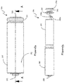
- FIG. 2a and FIG. 2b are a schematic structural view and an exploded perspective view showing an electrochemical battery 200 including a secondary electrochemical battery sealing body with a charging indicator according to the present invention, respectively.
- the electrochemical battery 100 includes a battery case 201, a battery cell 202 arranged within the battery case 201, a negative electrode cap 203, a circuit board module 204 arranged within space between the battery cell 202 and the negative electrode cap 203, and a positive electrode cap 205.
- the battery cell 202 is housed in the battery case 201, and located between the positive electrode cap 205 and the circuit board module 204.
- the battery case 201 is a steel case with a cylinder or cuboid shaped structure for outputting a positive electrode and fixing the circuit board module 204.
- the positive electrode cap 205 is rotated to the right so as to be integrally formed with the battery case 201, so as to constitute an positive electrode of the secondary battery 200.
- the circuit board module 204 is at least one layer of printed circuit boards (PCBs) with a first side and a second side, wherein the first side is directed towards the negative electrode cap 203 relative to the electrochemical battery 200, and the second side is directed towards the battery cell 202 relative to the electrochemical battery 200.
- the PCB is a circuit board having a wiring pattern printed thereon and is of a size substantially corresponding to an inner diameter of the case for the battery 200.
- a plurality of printed wires and components are arranged on the first side or second side of the circuit board module 204.
- the circuit board module 204 is in proximity to the side of the negative electrode cap 203 of the battery 200 and positioned between the battery cell 202 and the negative electrode cap 203.
- a connector is provided on the circuit board module 204 for fixing the negative electrode cap 203 onto the circuit board module 204.
- the negative electrode cap 203 may be fixed onto the circuit board module 204 by means of soldering or alternatively by means of clamping and the like.
- a circuit negative electrode output terminal of the circuit board module 204 is disposed at a portion where the negative electrode cap 203 and the circuit board are connected, so that the same wire is used for negative electrode output and circuit grounding.
- Electrode connecting wires 208a and 208b are provided between the circuit module 204 and the battery cell 202 for leading the positive electrode and a negative electrode out of the battery, respectively.
- the connecting wire for the positive electrode is denoted as 208a and the connecting wire for the negative electrode is denoted as 208b.
- FIG. 2c is a sectional view taken along a line A-A in FIG. 2a .
- An insulating washer 206 is provided between the circuit board module 204 and the battery case 201 outside, and between the negative electrode cap 203 and the battery case 201.
- the insulating washer 206 is a flexible and elastic annular insulating padding layer, and can play a role of isolating the battery case 201 that serves as a first electrode from the negative electrode cap 203 that serves as a second electrode, and can press and fix the circuit board module 204 due to the elasticity of the insulating padding layer to seal the gap between the battery case 201 and the negative electrode cap 203.
- one segments of the insulating washer206 are used to press and fix the circuit board module 204 between the loop line 207 and the battery case 201, and the other segments of the insulating washer 206 are used to isolate the battery case 201 from the negative electrode cap 203.
- a loop line207 is formed as an annular inward recess on an outer surface, corresponding to a location between the battery cell 202 and the printed circuit board, of the battery case 201.
- the battery cell 202 is arranged within the battery case 201 and positioned between the positive electrode cap 205 and the loop line 207 structure.
- the insulating washer 206 and the loop line 207 are arranged in such a manner that the circuit board module 204 is fixed between the annular recess of the battery case 201 and the bottom of the battery case 201. Therefore, the battery case 201 and the negative electrode cap 203 are connected without any soldering.
- the loop line 207 structure is configured to position the circuit board module 204.
- the circuit board module 204 is configured with the diameter thereof being sized between an inner diameter of the annular recess constituted by the loop line 207 and an inner diameter of the battery case 201.
- the battery cell 202 has a sealed structure and can be operated by leading a positive electrode and a negative electrode of the battery cell 202 out of the battery cell 202 so as to be connected to the positive electrode and the negative electrode of the battery respectively.
- the loop line 207 has a recess depth of 0.2 mm to 1.2 mm relative to the surface of the battery case 201.
- a sealing body for a secondary electrochemical battery with a charging indicator of the present invention has a cleverly and reasonably designed structure in that a charging indicator is arranged on a circuit board of the electrochemical battery, which can cooperate with a transparent insulating washer at a negative electrode of the battery, so that the whole insulating washer transmits light when the battery is charged, and thus charging indicating light is more visible.
Landscapes
- Chemical & Material Sciences (AREA)
- Chemical Kinetics & Catalysis (AREA)
- Electrochemistry (AREA)
- General Chemical & Material Sciences (AREA)
- Engineering & Computer Science (AREA)
- Manufacturing & Machinery (AREA)
- Power Engineering (AREA)
- Microelectronics & Electronic Packaging (AREA)
- Sealing Battery Cases Or Jackets (AREA)
- Charge And Discharge Circuits For Batteries Or The Like (AREA)
- Secondary Cells (AREA)
Claims (9)
- Un corps de scellage d'accumulateur électrochimique (100) avec un indicateur de chargement (105), le corps de scellage est configuré pour sceller une portion d'ouverture d'un boîtier d'accumulateur d'un accumulateur électrochimique, et le corps de scellage comprend un capuchon d'électrode négative (101), un module de carte de circuit imprimé (103), et une rondelle isolante (102),
le capuchon d'électrode négative (101) est situé sur un côté le plus à l'extérieur du corps de scellage d'accumulateur (100), et le module de carte de circuit imprimé (103) est situé sur un côté intérieur du capuchon d'électrode négative (101) et connecté au capuchon d'électrode négative (101) via un connecteur;
un indicateur de chargement (105) est disposé sur an emplacement sur le module de carte de circuit imprimé (103) qui correspond à un bord du capuchon d'électrode négative (101);
une portion où le capuchon d'électrode négative (101) et le module de carte de circuit imprimé (103) sont connectés est d'une structure annulaire d'une forme en C, c'est-à-dire que, un cran (104) est formé sur le bord du capuchon d'électrode négative (101), le cran est un port d'émission de lumière de l'indicateur de chargement (105), et le cran a une certaine hauteur mais n'est pas plus haut que le capuchon d'électrode négative (101), de sorte que l'indicateur de chargement (105) est exposé, et une position du cran correspond à une position de l'indicateur de chargement (105) sur le module de carte de circuit imprimé (103); et
la rondelle isolante (102) est une rondelle isolante annulaire flexible et élastique, et la rondelle isolante est adaptée à être disposée dans des jeux entre le boîtier d'accumulateur et le module de carte de circuit imprimé et entre le boîtier d'accumulateur et le capuchon d'électrode négative, un segment de la rondelle isolante est adapté à appuyer sur et fixer le module de carte de circuit imprimé, et un autre segment est adapté à isoler le boîtier d'accumulateur du capuchon d'électrode négative (101), la rondelle isolante (102) en outre couvre complètement le port d'émission de lumière de l'indicateur de chargement (105), pour être adapté à sceller le capuchon d'électrode négative (101), le boîtier d'accumulateur, et le module de carte de circuit imprimé, et la rondelle isolante (102) est réalisée en un matériau transparent de guidage de lumière, de sorte que la lumière émise par l'indicateur de chargement passe à travers la rondelle isolante, et la rondelle isolante entière est permise de transmettre de la lumière. - Le corps de scellage d'accumulateur électrochimique selon revendication 1, dans lequel, l'indicateur de chargement (105) a au moins une couleur.
- Le corps de scellage d'accumulateur électrochimique selon revendication 2, dans lequel, lorsque l'indicateur de chargement (105) a une couleur, l'indicateur de chargement est constamment allumé dans la couleur durant un chargement, et éteint lorsque le chargement est complété.
- Le corps de scellage d'accumulateur électrochimique selon revendication 2, dans lequel, lorsque l'indicateur de chargement (105) a deux couleurs, l'indicateur de chargement est constamment allumé dans une couleur durant un chargement, et constamment allumé dans l'autre couleur lorsque le chargement est complété.
- Le corps de scellage d'accumulateur électrochimique selon revendication 2, dans lequel, lorsqu'une défaillance se produit pendant un chargement, l'indicateur de chargement (105) clignote.
- Le corps de scellage d'accumulateur électrochimique selon revendication 2, dans lequel, dans des phases plus tôt, intermédiaire, et plus tard d'un chargement, l'indicateur de chargement (105) clignote à une fréquence décroissante, et l'indicateur de chargement est constamment allumé lorsque le chargement est complété.
- Le corps de scellage d'accumulateur électrochimique selon revendication 1, dans lequel, le module de carte de circuit imprimé (103) et le capuchon d'électrode négative (101) sont connectés au moyen d'un soudage.
- Le corps de scellage d'accumulateur électrochimique selon revendication 1, dans lequel, une sortie d'électrode négative de circuit du module de carte de circuit imprimé (103) est disposée à une portion où le capuchon d'électrode négative (101) et la carte de circuit imprimé sont connectés, de sorte qu'un même fil est utilisé pour la sortie d'électrode négative et la mise à la terre de circuit.
- Un accumulateur électrochimique (200) comprenant le corps de scellage d'accumulateur selon revendication 1, dans lequel, le corps de scellage est configuré pour sceller une portion d'ouverture d'un boîtier d'accumulateur (201) de l'accumulateur électrochimique, et l'accumulateur électrochimique comprend en outre une cellule d'accumulateur (202) et un capuchon d'électrode positive (205), dans lequel,
le capuchon d'électrode positive (205) est connecté au boîtier d'accumulateur (201) pour constituer une électrode positive de l'accumulateur électrochimique; et
la cellule d'accumulateur (202) est disposée au sein du boîtier d'accumulateur (201), et située entre le capuchon d'électrode positive (205) et le module de carte de circuit imprimé.
Applications Claiming Priority (3)
| Application Number | Priority Date | Filing Date | Title |
|---|---|---|---|
| CN201510324116.5A CN104993092B (zh) | 2015-06-12 | 2015-06-12 | 一种带有充电指示灯的二次电化学电池封口体 |
| CN201520406542.9U CN204668385U (zh) | 2015-06-12 | 2015-06-12 | 一种带有充电指示灯的二次电化学电池封口体 |
| PCT/CN2015/096610 WO2016197565A1 (fr) | 2015-06-12 | 2015-12-08 | Corps hermétique de cellule électrochimique secondaire présentant un voyant lumineux rechargeable |
Publications (3)
| Publication Number | Publication Date |
|---|---|
| EP3291335A1 EP3291335A1 (fr) | 2018-03-07 |
| EP3291335A4 EP3291335A4 (fr) | 2018-03-21 |
| EP3291335B1 true EP3291335B1 (fr) | 2019-09-11 |
Family
ID=57502843
Family Applications (1)
| Application Number | Title | Priority Date | Filing Date |
|---|---|---|---|
| EP15894820.8A Active EP3291335B1 (fr) | 2015-06-12 | 2015-12-08 | Corps hermétique de cellule électrochimique secondaire présentant un voyant lumineux rechargeable |
Country Status (5)
| Country | Link |
|---|---|
| US (1) | US20170338450A1 (fr) |
| EP (1) | EP3291335B1 (fr) |
| JP (1) | JP6533310B2 (fr) |
| ES (1) | ES2768826T3 (fr) |
| WO (1) | WO2016197565A1 (fr) |
Families Citing this family (3)
| Publication number | Priority date | Publication date | Assignee | Title |
|---|---|---|---|---|
| WO2016197566A1 (fr) * | 2015-06-12 | 2016-12-15 | 福建南平南孚电池有限公司 | Corps d'étanchéité de pile électrochimique rechargeable à structure de blindage de puce encapsulée et pile |
| DE102017216561A1 (de) * | 2017-09-19 | 2019-03-21 | Siemens Aktiengesellschaft | Batterieanordnung |
| CN111769337B (zh) * | 2020-01-17 | 2024-09-13 | 广东美尼麦格松电源系统有限公司 | 柱状电池及其带有指示灯的控制器 |
Citations (1)
| Publication number | Priority date | Publication date | Assignee | Title |
|---|---|---|---|---|
| WO2015039584A1 (fr) * | 2013-09-23 | 2015-03-26 | 李松 | Pile rechargeable universelle constituée par l'utilisation d'une pile au lithium-ion et procédé de commande |
Family Cites Families (10)
| Publication number | Priority date | Publication date | Assignee | Title |
|---|---|---|---|---|
| JP2507777Y2 (ja) * | 1990-07-06 | 1996-08-21 | 三洋電機株式会社 | 充電有無表示機構付電池 |
| KR20020095025A (ko) * | 1999-06-21 | 2002-12-20 | 더 보오드 오브 트러스티스 오브 더 유니버시티 오브 일리노이즈 | 전자 회로용 하우징을 구비한 배터리 |
| JP5055824B2 (ja) * | 2006-05-09 | 2012-10-24 | ソニー株式会社 | 電池 |
| US20080160392A1 (en) * | 2006-12-29 | 2008-07-03 | Shoichi Toya | Cylindrical battery |
| JP5164491B2 (ja) * | 2006-12-29 | 2013-03-21 | 三洋電機株式会社 | 筒形電池 |
| TWM385097U (en) * | 2010-01-05 | 2010-07-21 | Hercules Electronics Co Ltd | Secondary battery |
| CN202423479U (zh) * | 2011-10-21 | 2012-09-05 | 罗文翰 | 一种能伸缩、互配、相连的多功能的充放蓄电池 |
| JP5878564B2 (ja) * | 2012-01-11 | 2016-03-08 | 日立マクセル株式会社 | 電池ユニット |
| CN104993092B (zh) * | 2015-06-12 | 2017-03-08 | 福建南平南孚电池有限公司 | 一种带有充电指示灯的二次电化学电池封口体 |
| CN204668385U (zh) * | 2015-06-12 | 2015-09-23 | 福建南平南孚电池有限公司 | 一种带有充电指示灯的二次电化学电池封口体 |
-
2015
- 2015-12-08 WO PCT/CN2015/096610 patent/WO2016197565A1/fr not_active Ceased
- 2015-12-08 ES ES15894820T patent/ES2768826T3/es active Active
- 2015-12-08 JP JP2017562345A patent/JP6533310B2/ja active Active
- 2015-12-08 EP EP15894820.8A patent/EP3291335B1/fr active Active
-
2017
- 2017-08-09 US US15/672,795 patent/US20170338450A1/en not_active Abandoned
Patent Citations (2)
| Publication number | Priority date | Publication date | Assignee | Title |
|---|---|---|---|---|
| WO2015039584A1 (fr) * | 2013-09-23 | 2015-03-26 | 李松 | Pile rechargeable universelle constituée par l'utilisation d'une pile au lithium-ion et procédé de commande |
| EP3051622A1 (fr) * | 2013-09-23 | 2016-08-03 | Shenzhen Maigesong Electrical Co., Ltd. | Pile rechargeable universelle constituée par l'utilisation d'une pile au lithium-ion et procédé de commande |
Also Published As
| Publication number | Publication date |
|---|---|
| ES2768826T3 (es) | 2020-06-23 |
| EP3291335A4 (fr) | 2018-03-21 |
| JP2018518808A (ja) | 2018-07-12 |
| JP6533310B2 (ja) | 2019-06-19 |
| WO2016197565A1 (fr) | 2016-12-15 |
| US20170338450A1 (en) | 2017-11-23 |
| EP3291335A1 (fr) | 2018-03-07 |
Similar Documents
| Publication | Publication Date | Title |
|---|---|---|
| EP3291328B1 (fr) | Batterie secondaire électrochimique ayant un circuit de charge incorporé | |
| EP1599915B1 (fr) | Batteries au lithium-ion | |
| KR101671371B1 (ko) | 비돌출 구조의 커넥터를 포함하고 있는 이차전지 팩 | |
| US8415038B2 (en) | Secondary battery having external terminals | |
| EP3297056B1 (fr) | Pile électrochimique rechargeable avec un corps d'étanchéité et une structure de blindage de puce encapsulée | |
| EP2200111B1 (fr) | Bloc-batteries | |
| KR101016852B1 (ko) | 이차 전지 | |
| JP3498538B2 (ja) | 二次電池及び二次電池用組立封口板 | |
| EP3291335B1 (fr) | Corps hermétique de cellule électrochimique secondaire présentant un voyant lumineux rechargeable | |
| CN104993092A (zh) | 一种带有充电指示灯的二次电化学电池封口体 | |
| US20150155545A1 (en) | Battery pack | |
| JP5996302B2 (ja) | 電池ユニット | |
| WO2016197563A1 (fr) | Corps étanche d'une électrode négative d'un accumulateur | |
| CN204668385U (zh) | 一种带有充电指示灯的二次电化学电池封口体 | |
| KR20010092656A (ko) | 전지를 내장한 휴대전기기기 | |
| CN216903258U (zh) | 一种纽扣电池 | |
| CN104900840B (zh) | 一种用于二次电池负极封口体的密封圈 | |
| KR20040110332A (ko) | 이차 전지 | |
| KR101973055B1 (ko) | 회로보호모듈 일체형 캡 조립체, 캡 조립체의 제조 방법, 및 이차 전지 | |
| KR20140083875A (ko) | 배터리팩 | |
| KR20090026698A (ko) | 전지 팩 | |
| KR20060027692A (ko) | 전자기기용 전지 |
Legal Events
| Date | Code | Title | Description |
|---|---|---|---|
| STAA | Information on the status of an ep patent application or granted ep patent |
Free format text: STATUS: THE INTERNATIONAL PUBLICATION HAS BEEN MADE |
|
| PUAI | Public reference made under article 153(3) epc to a published international application that has entered the european phase |
Free format text: ORIGINAL CODE: 0009012 |
|
| STAA | Information on the status of an ep patent application or granted ep patent |
Free format text: STATUS: REQUEST FOR EXAMINATION WAS MADE |
|
| 17P | Request for examination filed |
Effective date: 20171130 |
|
| AK | Designated contracting states |
Kind code of ref document: A1 Designated state(s): AL AT BE BG CH CY CZ DE DK EE ES FI FR GB GR HR HU IE IS IT LI LT LU LV MC MK MT NL NO PL PT RO RS SE SI SK SM TR |
|
| AX | Request for extension of the european patent |
Extension state: BA ME |
|
| A4 | Supplementary search report drawn up and despatched |
Effective date: 20180219 |
|
| RIC1 | Information provided on ipc code assigned before grant |
Ipc: H01M 10/42 20060101ALI20180213BHEP Ipc: H01M 10/48 20060101ALI20180213BHEP Ipc: H01M 10/04 20060101ALI20180213BHEP Ipc: H01M 2/04 20060101ALI20180213BHEP Ipc: H01M 2/30 20060101AFI20180213BHEP Ipc: H02J 7/00 20060101ALI20180213BHEP Ipc: H01M 10/0525 20100101ALI20180213BHEP Ipc: H01M 2/08 20060101ALI20180213BHEP |
|
| STAA | Information on the status of an ep patent application or granted ep patent |
Free format text: STATUS: EXAMINATION IS IN PROGRESS |
|
| 17Q | First examination report despatched |
Effective date: 20180807 |
|
| 17Q | First examination report despatched |
Effective date: 20180815 |
|
| DAV | Request for validation of the european patent (deleted) | ||
| DAX | Request for extension of the european patent (deleted) | ||
| 17Q | First examination report despatched |
Effective date: 20180823 |
|
| GRAP | Despatch of communication of intention to grant a patent |
Free format text: ORIGINAL CODE: EPIDOSNIGR1 |
|
| STAA | Information on the status of an ep patent application or granted ep patent |
Free format text: STATUS: GRANT OF PATENT IS INTENDED |
|
| INTG | Intention to grant announced |
Effective date: 20190425 |
|
| GRAS | Grant fee paid |
Free format text: ORIGINAL CODE: EPIDOSNIGR3 |
|
| GRAA | (expected) grant |
Free format text: ORIGINAL CODE: 0009210 |
|
| STAA | Information on the status of an ep patent application or granted ep patent |
Free format text: STATUS: THE PATENT HAS BEEN GRANTED |
|
| AK | Designated contracting states |
Kind code of ref document: B1 Designated state(s): AL AT BE BG CH CY CZ DE DK EE ES FI FR GB GR HR HU IE IS IT LI LT LU LV MC MK MT NL NO PL PT RO RS SE SI SK SM TR |
|
| REG | Reference to a national code |
Ref country code: GB Ref legal event code: FG4D |
|
| REG | Reference to a national code |
Ref country code: CH Ref legal event code: EP |
|
| REG | Reference to a national code |
Ref country code: AT Ref legal event code: REF Ref document number: 1179642 Country of ref document: AT Kind code of ref document: T Effective date: 20190915 |
|
| REG | Reference to a national code |
Ref country code: DE Ref legal event code: R096 Ref document number: 602015038049 Country of ref document: DE Ref country code: IE Ref legal event code: FG4D |
|
| REG | Reference to a national code |
Ref country code: NL Ref legal event code: MP Effective date: 20190911 |
|
| REG | Reference to a national code |
Ref country code: LT Ref legal event code: MG4D |
|
| PG25 | Lapsed in a contracting state [announced via postgrant information from national office to epo] |
Ref country code: LT Free format text: LAPSE BECAUSE OF FAILURE TO SUBMIT A TRANSLATION OF THE DESCRIPTION OR TO PAY THE FEE WITHIN THE PRESCRIBED TIME-LIMIT Effective date: 20190911 Ref country code: FI Free format text: LAPSE BECAUSE OF FAILURE TO SUBMIT A TRANSLATION OF THE DESCRIPTION OR TO PAY THE FEE WITHIN THE PRESCRIBED TIME-LIMIT Effective date: 20190911 Ref country code: BG Free format text: LAPSE BECAUSE OF FAILURE TO SUBMIT A TRANSLATION OF THE DESCRIPTION OR TO PAY THE FEE WITHIN THE PRESCRIBED TIME-LIMIT Effective date: 20191211 Ref country code: NO Free format text: LAPSE BECAUSE OF FAILURE TO SUBMIT A TRANSLATION OF THE DESCRIPTION OR TO PAY THE FEE WITHIN THE PRESCRIBED TIME-LIMIT Effective date: 20191211 Ref country code: SE Free format text: LAPSE BECAUSE OF FAILURE TO SUBMIT A TRANSLATION OF THE DESCRIPTION OR TO PAY THE FEE WITHIN THE PRESCRIBED TIME-LIMIT Effective date: 20190911 Ref country code: HR Free format text: LAPSE BECAUSE OF FAILURE TO SUBMIT A TRANSLATION OF THE DESCRIPTION OR TO PAY THE FEE WITHIN THE PRESCRIBED TIME-LIMIT Effective date: 20190911 |
|
| PG25 | Lapsed in a contracting state [announced via postgrant information from national office to epo] |
Ref country code: LV Free format text: LAPSE BECAUSE OF FAILURE TO SUBMIT A TRANSLATION OF THE DESCRIPTION OR TO PAY THE FEE WITHIN THE PRESCRIBED TIME-LIMIT Effective date: 20190911 Ref country code: RS Free format text: LAPSE BECAUSE OF FAILURE TO SUBMIT A TRANSLATION OF THE DESCRIPTION OR TO PAY THE FEE WITHIN THE PRESCRIBED TIME-LIMIT Effective date: 20190911 Ref country code: GR Free format text: LAPSE BECAUSE OF FAILURE TO SUBMIT A TRANSLATION OF THE DESCRIPTION OR TO PAY THE FEE WITHIN THE PRESCRIBED TIME-LIMIT Effective date: 20191212 Ref country code: AL Free format text: LAPSE BECAUSE OF FAILURE TO SUBMIT A TRANSLATION OF THE DESCRIPTION OR TO PAY THE FEE WITHIN THE PRESCRIBED TIME-LIMIT Effective date: 20190911 |
|
| REG | Reference to a national code |
Ref country code: AT Ref legal event code: MK05 Ref document number: 1179642 Country of ref document: AT Kind code of ref document: T Effective date: 20190911 |
|
| PG25 | Lapsed in a contracting state [announced via postgrant information from national office to epo] |
Ref country code: EE Free format text: LAPSE BECAUSE OF FAILURE TO SUBMIT A TRANSLATION OF THE DESCRIPTION OR TO PAY THE FEE WITHIN THE PRESCRIBED TIME-LIMIT Effective date: 20190911 Ref country code: AT Free format text: LAPSE BECAUSE OF FAILURE TO SUBMIT A TRANSLATION OF THE DESCRIPTION OR TO PAY THE FEE WITHIN THE PRESCRIBED TIME-LIMIT Effective date: 20190911 Ref country code: PL Free format text: LAPSE BECAUSE OF FAILURE TO SUBMIT A TRANSLATION OF THE DESCRIPTION OR TO PAY THE FEE WITHIN THE PRESCRIBED TIME-LIMIT Effective date: 20190911 Ref country code: PT Free format text: LAPSE BECAUSE OF FAILURE TO SUBMIT A TRANSLATION OF THE DESCRIPTION OR TO PAY THE FEE WITHIN THE PRESCRIBED TIME-LIMIT Effective date: 20200113 Ref country code: RO Free format text: LAPSE BECAUSE OF FAILURE TO SUBMIT A TRANSLATION OF THE DESCRIPTION OR TO PAY THE FEE WITHIN THE PRESCRIBED TIME-LIMIT Effective date: 20190911 Ref country code: NL Free format text: LAPSE BECAUSE OF FAILURE TO SUBMIT A TRANSLATION OF THE DESCRIPTION OR TO PAY THE FEE WITHIN THE PRESCRIBED TIME-LIMIT Effective date: 20190911 |
|
| PG25 | Lapsed in a contracting state [announced via postgrant information from national office to epo] |
Ref country code: SM Free format text: LAPSE BECAUSE OF FAILURE TO SUBMIT A TRANSLATION OF THE DESCRIPTION OR TO PAY THE FEE WITHIN THE PRESCRIBED TIME-LIMIT Effective date: 20190911 Ref country code: SK Free format text: LAPSE BECAUSE OF FAILURE TO SUBMIT A TRANSLATION OF THE DESCRIPTION OR TO PAY THE FEE WITHIN THE PRESCRIBED TIME-LIMIT Effective date: 20190911 Ref country code: CZ Free format text: LAPSE BECAUSE OF FAILURE TO SUBMIT A TRANSLATION OF THE DESCRIPTION OR TO PAY THE FEE WITHIN THE PRESCRIBED TIME-LIMIT Effective date: 20190911 Ref country code: IS Free format text: LAPSE BECAUSE OF FAILURE TO SUBMIT A TRANSLATION OF THE DESCRIPTION OR TO PAY THE FEE WITHIN THE PRESCRIBED TIME-LIMIT Effective date: 20200224 |
|
| REG | Reference to a national code |
Ref country code: DE Ref legal event code: R097 Ref document number: 602015038049 Country of ref document: DE |
|
| REG | Reference to a national code |
Ref country code: ES Ref legal event code: FG2A Ref document number: 2768826 Country of ref document: ES Kind code of ref document: T3 Effective date: 20200623 |
|
| PLBE | No opposition filed within time limit |
Free format text: ORIGINAL CODE: 0009261 |
|
| STAA | Information on the status of an ep patent application or granted ep patent |
Free format text: STATUS: NO OPPOSITION FILED WITHIN TIME LIMIT |
|
| PG2D | Information on lapse in contracting state deleted |
Ref country code: IS |
|
| PG25 | Lapsed in a contracting state [announced via postgrant information from national office to epo] |
Ref country code: DK Free format text: LAPSE BECAUSE OF FAILURE TO SUBMIT A TRANSLATION OF THE DESCRIPTION OR TO PAY THE FEE WITHIN THE PRESCRIBED TIME-LIMIT Effective date: 20190911 Ref country code: IS Free format text: LAPSE BECAUSE OF FAILURE TO SUBMIT A TRANSLATION OF THE DESCRIPTION OR TO PAY THE FEE WITHIN THE PRESCRIBED TIME-LIMIT Effective date: 20200112 |
|
| REG | Reference to a national code |
Ref country code: CH Ref legal event code: PL |
|
| 26N | No opposition filed |
Effective date: 20200615 |
|
| REG | Reference to a national code |
Ref country code: BE Ref legal event code: MM Effective date: 20191231 |
|
| PG25 | Lapsed in a contracting state [announced via postgrant information from national office to epo] |
Ref country code: SI Free format text: LAPSE BECAUSE OF FAILURE TO SUBMIT A TRANSLATION OF THE DESCRIPTION OR TO PAY THE FEE WITHIN THE PRESCRIBED TIME-LIMIT Effective date: 20190911 Ref country code: MC Free format text: LAPSE BECAUSE OF FAILURE TO SUBMIT A TRANSLATION OF THE DESCRIPTION OR TO PAY THE FEE WITHIN THE PRESCRIBED TIME-LIMIT Effective date: 20190911 |
|
| PG25 | Lapsed in a contracting state [announced via postgrant information from national office to epo] |
Ref country code: LU Free format text: LAPSE BECAUSE OF NON-PAYMENT OF DUE FEES Effective date: 20191208 Ref country code: IE Free format text: LAPSE BECAUSE OF NON-PAYMENT OF DUE FEES Effective date: 20191208 |
|
| REG | Reference to a national code |
Ref country code: DE Ref legal event code: R079 Ref document number: 602015038049 Country of ref document: DE Free format text: PREVIOUS MAIN CLASS: H01M0002300000 Ipc: H01M0050543000 |
|
| PG25 | Lapsed in a contracting state [announced via postgrant information from national office to epo] |
Ref country code: BE Free format text: LAPSE BECAUSE OF NON-PAYMENT OF DUE FEES Effective date: 20191231 Ref country code: LI Free format text: LAPSE BECAUSE OF NON-PAYMENT OF DUE FEES Effective date: 20191231 Ref country code: CH Free format text: LAPSE BECAUSE OF NON-PAYMENT OF DUE FEES Effective date: 20191231 |
|
| PG25 | Lapsed in a contracting state [announced via postgrant information from national office to epo] |
Ref country code: CY Free format text: LAPSE BECAUSE OF FAILURE TO SUBMIT A TRANSLATION OF THE DESCRIPTION OR TO PAY THE FEE WITHIN THE PRESCRIBED TIME-LIMIT Effective date: 20190911 |
|
| PG25 | Lapsed in a contracting state [announced via postgrant information from national office to epo] |
Ref country code: HU Free format text: LAPSE BECAUSE OF FAILURE TO SUBMIT A TRANSLATION OF THE DESCRIPTION OR TO PAY THE FEE WITHIN THE PRESCRIBED TIME-LIMIT; INVALID AB INITIO Effective date: 20151208 Ref country code: MT Free format text: LAPSE BECAUSE OF FAILURE TO SUBMIT A TRANSLATION OF THE DESCRIPTION OR TO PAY THE FEE WITHIN THE PRESCRIBED TIME-LIMIT Effective date: 20190911 |
|
| PG25 | Lapsed in a contracting state [announced via postgrant information from national office to epo] |
Ref country code: TR Free format text: LAPSE BECAUSE OF FAILURE TO SUBMIT A TRANSLATION OF THE DESCRIPTION OR TO PAY THE FEE WITHIN THE PRESCRIBED TIME-LIMIT Effective date: 20190911 |
|
| PG25 | Lapsed in a contracting state [announced via postgrant information from national office to epo] |
Ref country code: MK Free format text: LAPSE BECAUSE OF FAILURE TO SUBMIT A TRANSLATION OF THE DESCRIPTION OR TO PAY THE FEE WITHIN THE PRESCRIBED TIME-LIMIT Effective date: 20190911 |
|
| PGFP | Annual fee paid to national office [announced via postgrant information from national office to epo] |
Ref country code: GB Payment date: 20251229 Year of fee payment: 11 |
|
| PGFP | Annual fee paid to national office [announced via postgrant information from national office to epo] |
Ref country code: IT Payment date: 20251211 Year of fee payment: 11 |
|
| PGFP | Annual fee paid to national office [announced via postgrant information from national office to epo] |
Ref country code: FR Payment date: 20251230 Year of fee payment: 11 |
|
| PGFP | Annual fee paid to national office [announced via postgrant information from national office to epo] |
Ref country code: ES Payment date: 20260112 Year of fee payment: 11 |
|
| PGFP | Annual fee paid to national office [announced via postgrant information from national office to epo] |
Ref country code: DE Payment date: 20251231 Year of fee payment: 11 |