EP3291348B1 - Brennstoffzellenmodul - Google Patents
Brennstoffzellenmodul Download PDFInfo
- Publication number
- EP3291348B1 EP3291348B1 EP17177242.9A EP17177242A EP3291348B1 EP 3291348 B1 EP3291348 B1 EP 3291348B1 EP 17177242 A EP17177242 A EP 17177242A EP 3291348 B1 EP3291348 B1 EP 3291348B1
- Authority
- EP
- European Patent Office
- Prior art keywords
- hydrodesulfurizer
- fuel
- cell module
- fuel cell
- air
- Prior art date
- Legal status (The legal status is an assumption and is not a legal conclusion. Google has not performed a legal analysis and makes no representation as to the accuracy of the status listed.)
- Active
Links
Images





Classifications
-
- H—ELECTRICITY
- H01—ELECTRIC ELEMENTS
- H01M—PROCESSES OR MEANS, e.g. BATTERIES, FOR THE DIRECT CONVERSION OF CHEMICAL ENERGY INTO ELECTRICAL ENERGY
- H01M8/00—Fuel cells; Manufacture thereof
- H01M8/06—Combination of fuel cells with means for production of reactants or for treatment of residues
- H01M8/0662—Treatment of gaseous reactants or gaseous residues, e.g. cleaning
- H01M8/0675—Removal of sulfur
-
- H—ELECTRICITY
- H01—ELECTRIC ELEMENTS
- H01M—PROCESSES OR MEANS, e.g. BATTERIES, FOR THE DIRECT CONVERSION OF CHEMICAL ENERGY INTO ELECTRICAL ENERGY
- H01M8/00—Fuel cells; Manufacture thereof
- H01M8/002—Shape, form of a fuel cell
-
- H—ELECTRICITY
- H01—ELECTRIC ELEMENTS
- H01M—PROCESSES OR MEANS, e.g. BATTERIES, FOR THE DIRECT CONVERSION OF CHEMICAL ENERGY INTO ELECTRICAL ENERGY
- H01M8/00—Fuel cells; Manufacture thereof
- H01M8/02—Details
- H01M8/0202—Collectors; Separators, e.g. bipolar separators; Interconnectors
-
- H—ELECTRICITY
- H01—ELECTRIC ELEMENTS
- H01M—PROCESSES OR MEANS, e.g. BATTERIES, FOR THE DIRECT CONVERSION OF CHEMICAL ENERGY INTO ELECTRICAL ENERGY
- H01M8/00—Fuel cells; Manufacture thereof
- H01M8/04—Auxiliary arrangements, e.g. for control of pressure or for circulation of fluids
- H01M8/04007—Auxiliary arrangements, e.g. for control of pressure or for circulation of fluids related to heat exchange
- H01M8/04014—Heat exchange using gaseous fluids; Heat exchange by combustion of reactants
-
- H—ELECTRICITY
- H01—ELECTRIC ELEMENTS
- H01M—PROCESSES OR MEANS, e.g. BATTERIES, FOR THE DIRECT CONVERSION OF CHEMICAL ENERGY INTO ELECTRICAL ENERGY
- H01M8/00—Fuel cells; Manufacture thereof
- H01M8/04—Auxiliary arrangements, e.g. for control of pressure or for circulation of fluids
- H01M8/04298—Processes for controlling fuel cells or fuel cell systems
- H01M8/04313—Processes for controlling fuel cells or fuel cell systems characterised by the detection or assessment of variables; characterised by the detection or assessment of failure or abnormal function
- H01M8/0432—Temperature; Ambient temperature
-
- H—ELECTRICITY
- H01—ELECTRIC ELEMENTS
- H01M—PROCESSES OR MEANS, e.g. BATTERIES, FOR THE DIRECT CONVERSION OF CHEMICAL ENERGY INTO ELECTRICAL ENERGY
- H01M8/00—Fuel cells; Manufacture thereof
- H01M8/06—Combination of fuel cells with means for production of reactants or for treatment of residues
- H01M8/0606—Combination of fuel cells with means for production of reactants or for treatment of residues with means for production of gaseous reactants
- H01M8/0612—Combination of fuel cells with means for production of reactants or for treatment of residues with means for production of gaseous reactants from carbon-containing material
- H01M8/0618—Reforming processes, e.g. autothermal, partial oxidation or steam reforming
-
- H—ELECTRICITY
- H01—ELECTRIC ELEMENTS
- H01M—PROCESSES OR MEANS, e.g. BATTERIES, FOR THE DIRECT CONVERSION OF CHEMICAL ENERGY INTO ELECTRICAL ENERGY
- H01M8/00—Fuel cells; Manufacture thereof
- H01M8/10—Fuel cells with solid electrolytes
- H01M8/12—Fuel cells with solid electrolytes operating at high temperature, e.g. with stabilised ZrO2 electrolyte
- H01M2008/1293—Fuel cells with solid oxide electrolytes
-
- Y—GENERAL TAGGING OF NEW TECHNOLOGICAL DEVELOPMENTS; GENERAL TAGGING OF CROSS-SECTIONAL TECHNOLOGIES SPANNING OVER SEVERAL SECTIONS OF THE IPC; TECHNICAL SUBJECTS COVERED BY FORMER USPC CROSS-REFERENCE ART COLLECTIONS [XRACs] AND DIGESTS
- Y02—TECHNOLOGIES OR APPLICATIONS FOR MITIGATION OR ADAPTATION AGAINST CLIMATE CHANGE
- Y02E—REDUCTION OF GREENHOUSE GAS [GHG] EMISSIONS, RELATED TO ENERGY GENERATION, TRANSMISSION OR DISTRIBUTION
- Y02E60/00—Enabling technologies; Technologies with a potential or indirect contribution to GHG emissions mitigation
- Y02E60/30—Hydrogen technology
- Y02E60/50—Fuel cells
Definitions
- Embodiments of the present invention relate to a fuel cell module.
- a fuel cell module that generates electric power using a hydrogen-containing gas and an oxygen-containing gas.
- the fuel cell module includes a solid oxide fuel cell housed in a package thereof.
- a fuel gas such as natural gas or petroleum gas, which are distributed commonly, is used.
- a sulfur component contained in the fuel gas is supplied to a reforming catalyst or the solid oxide fuel cell, it degrades the reforming catalyst or the solid oxide fuel cell. Therefore, a reformer or the solid oxide fuel cell is supplied with a fuel gas that is desulfurized with a desulfurizer.
- a catalyst for normal temperature desulfurization is generally used.
- a hydrodesulfurization catalyst which is higher in efficiency of desulfurization per volume than the catalyst for normal temperature desulfurization, is used.
- a heat source of 200 to 400°C is needed.
- liquid such as water enters the hydrodesulfurization catalyst, the liquid may degrade the hydrodesulfurization catalyst when it vaporizes, decreasing the efficiency of desulfurization.
- An objective of the present invention is to provide a fuel cell module in which the efficiency of desulfurization in a hydrodesulfurizer can be enhanced.
- EP 2887438 relates to a fuel cell system that includes a hydrodesulfurizer (2) that removes a sulfur compound from raw material and that is heated with heat of exhaust gas flowing in the fuel cell system (100); a fuel cell (1) that generates power through an electrochemical reaction using fuel and oxidant gas, the fuel being obtained by reforming raw material from which the sulfur compound has been removed by the hydrodesulfurizer (2); an introduction passage (6) through which the exhaust gas that is to heat the hydrodesulfurizer (2) passes; a first heat exchanger (5) disposed in the introduction passage (6) and that preheats, with heat of the exhaust gas passing through the introduction passage (6), the oxidant gas to be supplied to the fuel cell (1); and a second heat exchanger (4) that preheats, with heat of exhaust gas passing through a passage other than the introduction passage (6), the oxidant gas to be preheated by the first heat exchanger (5).
- US 2015/311533 relates to a fuel cell system using combustion heat for an evaporator and a desulfurizer effectively.
- the fuel cell system comprises a combustor, a reformer, a fuel cell, a first cathode air heating part, a desulfurizer and an evaporator.
- a mixture of oxygen and gas which is contained in fuel is combusted in the combustor.
- a combustion exhaust gas generated in the combustor flows in the fuel cell system in such a manner that the combustion exhaust gas gives thermal energy to the reformer, the first cathode air heating part, the desulfurizer, and the evaporator in this order.
- EP 3026744 relates to a fuel cell system (1) includes a desulfurizer (11) that removes a sulfur compound in a raw material, a fuel cell unit (50) that performs electric-power generation using fuel obtained by reforming a raw material from which the sulfur compound is removed and electric-power generation air supplied, a combustion exhaust gas passage through which combustion exhaust gas generated by combusting fuel not utilized for the electric-power generation in the fuel cell unit (50) is emitted, a combustion exhaust gas container (10) that is connected to the combustion exhaust gas passage and accommodates the desulfurizer (11) inside the combustion exhaust gas container (10), a purifier (12) that removes carbon monoxide included in the combustion exhaust gas, and an air heat exchanger (13) that performs heat exchange of the combustion exhaust gas and the electric-power generation air supplied to the fuel cell unit (50).
- a desulfurizer (11) that removes a sulfur compound in a raw material
- a fuel cell unit (50) that performs electric-power generation using fuel obtained by reforming a raw material from
- a fuel cell module is provided as recited in claim 1.
- a fuel cell system includes an air-preheating channel portion disposed between a hydrodesulfurizer and a cell stack and adjusts the flow of an oxygen-containing gas in the air-preheating channel portion, whereby heat conducted from the air-preheating channel portion to the hydrodesulfurizer is homogenized, so that the efficiency of desulfurization is enhanced.
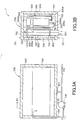
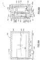
- FIGS. 1A and 1B are schematic views showing a configuration of a fuel cell module 1 according to the first reference example.
- FIG. 1A is a lateral cross sectional view of the fuel cell module 1
- FIG. 1B is a front cross sectional view of the fuel cell module 1.
- the fuel cell module 1 generates electric power using a hydrogen-containing gas and an oxygen-containing gas, the hydrogen-containing gas being generated by reforming a hydrocarbon-based fuel. More specifically, the fuel cell module 1 includes a hydrodesulfurizer 100, a reformer 200, a cell stack 300, a burner 400, an exhaust gas channel portion 500, an air-preheating channel portion 600, and a package 700.
- the hydrodesulfurizer 100 is configured to desulfurize a fuel gas using a hydrodesulfurization catalyst. That is, the hydrodesulfurizer 100 functions at 200 to 400°C, desulfurizing a fuel gas to which an odorant such as sulfur is added, so as to remove a sulfur component, whereby a desulfurized fuel gas is generated.
- an odorant such as sulfur
- the desulfurized fuel gas pipe 102 extends horizontally from the hydrodesulfurizer 100, then extends in a vertically upward direction, and communicates with the reformer 200. With this configuration, the hydrodesulfurizer 100 supplies the desulfurized fuel gas generated by the hydrodesulfurizer 100 to the reformer 200 through the desulfurized fuel gas pipe 102.
- the desulfurized fuel gas pipe 102 has an inner diameter enough to block water by means of capillary force.
- the inner diameter is, for example, 4.35 mm (an outer diameter is 1/4 inch).
- the stream of the desulfurized fuel gas in the desulfurized fuel gas pipe 102 is always directed from the hydrodesulfurizer 100 to the reformer 200 in a horizontal or the vertically upward direction. That is, the stream of the desulfurized fuel gas is not directed in a vertically downward direction; besides, the desulfurized fuel gas pipe 102 has a size that is small enough to block water by means of capillary force.
- the desulfurized fuel gas pipe 102 is supplied with water after the supply of the desulfurized fuel gas to the hydrodesulfurizer 100 is stopped. With this supply, the capillary force possessed by the desulfurized fuel gas pipe 102 blocks an outlet of the hydrodesulfurizer 100.
- the reformer 200 is supplied with water through a water supply pipe 202.
- the water supply pipe 202 merges with the desulfurized fuel gas pipe 102 at a confluence 203.
- the reformer 200 is configured to generate steam from the water supplied through the water supply pipe 202.
- the reformer 200 functions at 400 to 700°C and generates a hydrogen-containing gas using the water supplied through the water supply pipe 202 and the desulfurized fuel gas supplied through the desulfurized fuel gas pipe 102.
- the hydrogen-containing gas is supplied to the cell stack 300 through the reformer 200 and a hydrogen gas pipe 204 that communicates with the cell stack 300.
- a reforming catalyst provided inside the reformer 200 for example, a reforming catalyst in which a noble metal such as Ru (ruthenium) and Pt (platinum) and a base material such as Ni (nickel) and Fe (iron) are supported in a porous support such as alumina and cordierite, or another reforming catalyst, is used.
- a noble metal such as Ru (ruthenium) and Pt (platinum)
- a base material such as Ni (nickel) and Fe (iron) are supported in a porous support such as alumina and cordierite, or another reforming catalyst.
- the cell stack 300 is constituted by stacking a plurality of fuel cells and is configured to generate electric power using the hydrogen-containing gas supplied from the reformer 200 and the oxygen-containing gas (air) supplied via the air-preheating channel portion 600.
- the fuel cells mentioned here are stacked in a direction from the front to the depth of FIG. 1B , that is, in a width direction of FIG. 1A .
- the fuel cells of the cell stack 300 are each made up of a solid oxide fuel cell that operates at a high temperature of, for example, 500 to 1000°C.
- the plurality of fuel cells are electrically connected to each other.
- the fuel cells each include a fuel electrode and an oxidant electrode.
- the plurality of fuel cells generate electric power by the reaction expressed by Chemical Formula 1.
- the hydrogen-containing gas streams through a gas passage on a fuel-electrode side, inducing a fuel-electrode reaction.
- the oxygen-containing gas streams through a gas passage on an oxidant electrode side, inducing an oxidant electrode reaction.
- the burner 400 is a space between an upper portion of the cell stack 300 and the reformer 200.
- the burner 400 burns the hydrogen-containing gas that is not consumed by the cell stack 300, and the oxygen-containing gas, and discharges the resultant exhaust gas to the exhaust gas channel portion 500.
- the heat of the combustion heats the reformer 200, advancing a reforming reaction. This inhibits the above-described precipitation of carbon in the cell stack 300.
- the exhaust gas channel portion 500 is configured to discharge exhaust gas generated in the burner 400 to an outside of the fuel module. That is, the exhaust gas channel portion 500 is configured to discharge the hydrogen-containing gas that is not consumed by the cell stack 300, and discharge exhaust gas that is generated by the combustion of the oxygen-containing gas.
- the exhaust gas channel portion 500 and the cell stack 300 are not in contact with each other except for at an upper end of the cell.
- the air-preheating channel portion 600 is disposed so as to be adjacent to the exhaust gas channel portion 500 and is configured to preheat the oxygen-containing gas to be supplied to the cell stack 300, through heat exchange with the exhaust gas channel portion 500.
- the air-preheating channel portion 600 is disposed between the hydrodesulfurizer 100 and the cell stack 300. That is, the air-preheating channel portion 600 is in contact with the hydrodesulfurizer 100 directly or with a wall insulator interposed therebetween.
- one side of the cell stack 300 is covered, with the exhaust gas channel portion 500 interposed therebetween.
- the air-preheating channel portion 600 has a planar, hollowed shape, with which the one side of the hydrodesulfurizer 100 is covered, and includes an air channel that homogenizes distribution of heat conducted to the hydrodesulfurizer 100.
- the oxygen-containing gas streams in from an air inlet pipe 601.
- the air inlet pipe 601 is disposed in a lower portion of a central portion in the planar, hollowed shape.
- the air-preheating channel portion 600 includes a first air-preheating channel portion 600a, a second air-preheating channel portion 600b, a third air-preheating channel portion 600c, a fourth air-preheating channel portion 600d, and a fifth air-preheating channel portion 600e.
- the first air-preheating channel portion 600a extends from the lower portion to the upper portion of the fuel cell module 1 between the hydrodesulfurizer 100 and the exhaust gas channel portion 500
- the second air-preheating channel portion 600b is disposed in the upper portion.
- the third air-preheating channel portion 600c turns back at the upper portion and extends up to a lower face of the cell stack 300, the fourth air-preheating channel portion 600d is disposed in the lower portion, and the fifth air-preheating channel portion 600e communicates with the gas passage on an oxidant electrode side in the fuel cell.
- the third air-preheating channel portion 600c, the fourth air-preheating channel portion 600d, and the fifth air-preheating channel portion 600e do not perform heat exchange with the exhaust gas channel portion 500.
- air which is the oxygen-containing gas
- air inlet pipe 601 positioned in the lower portion of the fuel cell module 1, in the vicinity of a center of the cell stack 300 in a stacking direction of the cell stack 300.
- the air streams through the air-preheating channel portion 600 around the cell stack 300 and is heated through heat exchange with the exhaust gas channel portion 500.
- the heated air is supplied to the cell stack 300 from the lower portion of the cell stack 300.
- the package 700 houses the hydrodesulfurizer 100, the reformer 200, the cell stack 300, the burner 400, the exhaust gas channel portion 500, and the air-preheating channel portion 600.
- the package 700 includes an outer insulator 702.
- a fuel blower 106 communicates with the hydrodesulfurizer 100 through a fuel gas pipe 104.
- the fuel blower 106 supplies hydrogen and a hydrocarbon-based fuel gas that contains sulfur to the hydrodesulfurizer 100 through the fuel gas pipe 104.
- the fuel gas pipe 104 passes inside the outer insulator 702 in the package 700 until supplying fuel gas from the fuel blower 106 to the hydrodesulfurizer 100. This causes the fuel gas to receive heat from the fuel cell module 1 to be preheated.
- the fuel gas supplied through the fuel gas pipe 104 is a gas mainly containing hydrocarbon, such as a city gas (CNG) and a liquefied petroleum gas (LPG) that mainly contain a natural gas as their raw materials.
- the city gas (CNG) has a composition including, for example, 88% of methane, 7% of ethane (C 2 H 6 ), 4% of propane (C 3 H 8 ), and 1% of butane (C 4 H 10 ).
- the fuel gas pipe 104 is connected to a city gas line, an LPG line, a hydrogen line, or the like.
- the hydrodesulfurizer 100 is partitioned off with punched metals 108, and sections that are not filled with hydrodesulfurization catalysts are provided in the upper portion and the lower portion of the hydrodesulfurizer 100.
- a section partitioned off by the punched metals 108 is divided into three catalyst chambers 110, 112, and 114, each of which is filled with a hydrodesulfurization catalyst.
- partition plates 116 and 118 are placed in each of boundaries between the three catalyst chambers 110, 112, and 114.
- thermocouples serving as thermometers are placed, and the temperatures of INLET, T2, T3, OUTLET are measured.
- the hydrodesulfurizer 100 is in contact with the outer insulator 702 that is made of a high-performance insulator such as Microtherm and WDS.
- the resultant exhaust gas reaches 500 to 1000°C in the burner 400. Due to heat dissipation in end portions of the cell stack 300 and heat generation in the cell stack 300, the vicinity of the center of the cell stack 300 in the stacking direction reaches the most elevated temperature.
- the heat of the exhaust gas streaming through the exhaust gas channel portion 500 provided along a side face of this cell stack 300 and the heat of the oxygen-containing gas streaming through the air-preheating channel portion 600 perform heat exchange with each other. Therefore, the air-preheating channel portion 600 reflects a temperature distribution of the cell stack 300, and as to a temperature distribution conducted to the air-preheating channel, the vicinity of the center of the cell stack 300 in the stacking direction reaches the most elevated temperature.
- the air inlet pipe 601 of the air-preheating channel portion 600 is placed in the vicinity of the center of the cell stack 300 in the stacking direction, the amount of the oxygen-containing gas streaming along the central portion of the cell stack 300 in the stacking direction is larger than the amount of the oxygen-containing gas streaming along the end portions of the cell stack 300.
- This causes the stream of the oxygen-containing gas at a relatively low temperature to be concentrated in the center of the cell stack 300 in the stacking direction.
- the resultant exhaust gas is at a high temperature of 500 to 1000°C.
- the hydrodesulfurizer 100 is placed in the exhaust gas channel portion 500, it is difficult to keep the hydrodesulfurizer 100 at a temperature at which the hydrodesulfurization catalysts can perform the desulfurization appropriately.
- the air inlet pipe 601 of the air-preheating channel portion 600 is placed in the vicinity of the center of the cell stack 300 in the stacking direction. Therefore, the stream of the oxygen-containing gas at a relatively low temperature is concentrated in the center of the cell stack 300 in the stacking direction, and the temperature distribution of the air-preheating channel portion 600 is homogenized. This homogenizes the distribution of the heat conduction from the air-preheating channel portion 600 to the hydrodesulfurizer 100, which thereby enables a range of the temperatures of the hydrodesulfurization catalysts in the hydrodesulfurizer 100 to be kept appropriately.
- the upper portion and the lower portion of the hydrodesulfurizer 100 are partitioned off with the punched metals 108.
- This configuration reduces a pressure drop of the fuel gas, which makes the fuel gas stream easily. Therefore, the fuel gas streams into each of the catalyst chambers 110, 112, and 114 after the stream thereof are homogenized, and the fuel gas is discharged from each of the hydrodesulfurization catalysts uniformly. It is thereby possible to effectively desulfurize the fuel gas streaming in the hydrodesulfurizer 100, and to homogenize the temperature distribution in the hydrodesulfurizer 100.
- FIG. 2 is a table showing the temperatures measured at the locations (INLET, T2, T3, OUTLET) illustrated in FIG. 1 .
- the temperature in the hydrodesulfurizer 100 is kept from 200 to 400°C. Note that the temperature in the hydrodesulfurizer 100 in second to seventh embodiments, which will be explained later, are also measured at the locations (INLET, T2, T3, OUTLET) illustrated in FIG. 1 .
- FIG. 2 is a list of test results with the same amount of fuel stream, the same amount of air stream, the same amount of water stream, after the same elapsed time, and at the same measurement points in the hydrodesulfurizer.
- the hydrodesulfurizer 100 is placed across the single outer insulator 702, which provides easy access to the hydrodesulfurizer 100, facilitating the maintenance thereof.
- a fuel cell module according to a second embodiment differs from that in the first reference examplein that a low-performance wall insulator is placed between the hydrodesulfurizer and the air-preheating channel. Differences from the first reference examplewill be explained below.
- FIGS. 3A and 3B are schematic views showing a configuration of a fuel cell module 1 according to the second embodiment.
- FIG. 3A is a lateral cross sectional view of the fuel cell module 1.
- FIG. 3B is a front cross sectional view of the fuel cell module 1.
- the hydrodesulfurizer 100 and the air-preheating channel portion 600 are in direct contact with each other, but the present embodiment differs in that a low-performance wall insulator 802 is disposed between the hydrodesulfurizer 100 and the air-preheating channel portion 600.
- high-performance wall insulators 800 are placed on the top and the bottom of the hydrodesulfurizer 100, and the low-performance wall insulator 802 is placed between the hydrodesulfurizer 100 and the air-preheating channel.
- the insulating performance of the high-performance wall insulators 800 is the same as that of the outer insulator 702 of the package 700.
- the insulating performance of the low-performance wall insulator 802 is lower than that of the outer insulator 702 of the package 700 and lower than that of the high-performance wall insulators 800.
- the low-performance wall insulator 802 is, for example, a blanket-like insulator such as Superwool Plus from Shin-Nippon Thermal Ceramics Corporation and TOMBO from NICHIAS Corporation.
- the low-performance wall insulator 802 reduces heat conducted from the air-preheating channel portion 600 to the hydrodesulfurizer 100.
- the thickness of the outer insulator 702 is reduced by the thickness of the low-performance wall insulator 802. With this configuration, the outside dimensions of the entire fuel cell module 1 remain unchanged.
- the hydrodesulfurizer 100 is in contact with the air-preheating channel portion 600 with the low-performance wall insulator 802 interposed therebetween, the quantity of received heat is reduced.
- the high-performance wall insulators 800 are disposed in the upper portion and the lower portion of the hydrodesulfurizer 100, the quantity of heat conducted from the air-preheating channel portion 600 to the hydrodesulfurizer 100 is reduced.
- the low-performance wall insulator 802 is disposed between the hydrodesulfurizer 100 and the air-preheating channel portion 600. With this configuration, it is possible to reduce the quantity of received heat of the hydrodesulfurizer 100 and to reduce the temperature in the hydrodesulfurizer 100 even more.
- the high-performance wall insulators 800 are disposed in the upper portion and the lower portion of the hydrodesulfurizer 100. With this configuration, it is possible to reduce the quantity of heat conducted from the air-preheating channel portion 600 to the hydrodesulfurizer 100 even more.
- the maximum temperature of the hydrodesulfurizer 100 is reduced to 335°C, which enables the temperature of the hydrodesulfurizer 100 to be brought close to a temperature from 200 to 320°C at which the hydrodesulfurization catalysts perform the desulfurization more efficiently.
- a fuel cell module according to a third embodiment differs from that in the second embodiment in that the air-preheating channel portion includes a meandering channel. Differences from the second embodiment will be explained below.
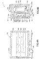
- FIGS. 4A and 4B are schematic views showing a configuration of a fuel cell module 1 according to the third embodiment.
- FIG. 4A is a lateral cross sectional view of a fuel cell module 1
- FIG. 4B is a front cross sectional view of the fuel cell module 1.
- the same components as those in the second embodiment are denoted by the same reference characters, and the explanation thereof will not be made.
- the air-preheating channel portion 600 at least includes a first channel plate 602, a second channel plate 604, a first partitioning portion 606, a second partitioning portion 608, and a third partitioning portion 610.
- the first channel plate 602 is made of a plate-like material.
- the second channel plate 604 is made of a plate-like material.
- the first channel plate 602 and the second channel plate 604 are in parallel to each other.
- the partitioning portions 606, 608, and 610 are each made of a plate having a thickness that fills a gap between the first channel plate 602 and the second channel plate 604.
- the partitioning portions 606, 608, and 610 may be each made of a round bar, which is fixed by spot welding, plug welding, and circumferential welding so that it fills the gap between the two channel plates.
- one or both of the two channel plates 602 and 604 may be subjected to pressing to be bent, forming contact surfaces, on which the partitioning portions 606, 608, and 610 may be fixed by spot welding, plug welding, and circumferential welding.
- the meandering channel can be formed without performing welding.
- a clearance between one end portion of each of the partitioning portions 606, 608, and 610 and the side wall of the air-preheating channel portion 600 differs from a clearance between the other end portion thereof and the side wall of the air-preheating channel portion 600.
- the position of a larger clearance between the end portion of each of the partitioning portions 606, 608, and 610 and the side wall of the air-preheating channel portion 600 is made different alternately among the partitioning portions 606, 608, and 610.
- This configuration forms the meandering channel through which air meanders laterally, as illustrated by arrows.
- the pressure drop is adjusted so as not to exceed a predetermined value.
- the meandering channel is formed in the air-preheating channel portion 600.
- the temperature in the hydrodesulfurizer 100 can be reduced as a whole more uniformly.
- the temperature in the hydrodesulfurizer 100 can be kept at a temperature from 200 to 320°C at which the hydrodesulfurization catalysts perform the desulfurization more efficiently.
- a fuel cell module according to a fourth embodiment differs from that in the third embodiment in that the insulating performance of the insulator placed between the hydrodesulfurizer and the air-preheating channel portion is changed based on the temperature distribution of the air-preheating channel portion. Differences from the third embodiment will be explained below.
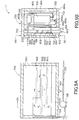
- FIGS. 5A and 5B are schematic views showing a configuration of a fuel cell module 1 according to the fourth embodiment.
- FIG. 5A is a lateral cross sectional view of a fuel cell module 1
- FIG. 5B is a front cross sectional view of the fuel cell module 1.
- the same components as those in the third embodiment are denoted by the same reference characters, and the explanation thereof will not be made.
- a wall insulator disposed between the hydrodesulfurizer 100 and the air-preheating channel portion 600 includes the low-performance wall insulator 802 and high-performance wall insulators 804.
- the high-performance wall insulators 804 are disposed at positions corresponding to those midstream and downstream of the hydrodesulfurizer 100.
- the positions of the air-preheating channel portion 600 corresponding to those midstream and downstream of the hydrodesulfurizer 100 are at higher temperatures than the temperatures of the other positions, and gas streaming through the positions midstream and downstream of the hydrodesulfurizer is also at a sufficiently high temperature.
- the high-performance wall insulators 804 are disposed so that the positions thereof correspond to the positions at higher temperatures in the air-preheating channel portion 600, and thus heat conducted from the air-preheating channel portion 600 to the hydrodesulfurizer 100 is homogenized even more.
- the insulating performance of the insulator placed between the hydrodesulfurizer 100 and the air-preheating channel portion 600 is changed based on the temperature distribution of the air-preheating channel portion 600.
- the quantities of received heat in high temperature portions (midstream and downstream regions) of the hydrodesulfurizer 100 are made even smaller. Therefore, it is possible to reduce the temperatures in the high temperature portions of the hydrodesulfurizer 100, and to homogenize the temperature distribution of the hydrodesulfurizer 100 as a whole.
- the temperature in the hydrodesulfurizer 100 can be kept at a temperature from 200 to 320°C at which the hydrodesulfurization catalysts perform the desulfurization more efficiently.
- a fuel cell module according to a fifth embodiment differs from that in the fourth embodiment in that a space through which air streams is formed in a central portion of the meandering channel in the air-preheating channel portion. Differences from the fourth embodiment will be explained below.
- FIGS. 6A and 36 are schematic views showing a configuration of a fuel cell module 1 according to the fifth embodiment.
- FIG. 6A is a lateral cross sectional view of a fuel cell module 1
- FIG. 6B is a front cross sectional view of the fuel cell module 1.
- the same components as those in the fourth embodiment are denoted by the same reference characters, and the explanation thereof will not be made.
- the fuel cell module 1 according to the fifth embodiment differs from that in the fourth embodiment in that a space through which air streams is provided in central portions 616 and 618 of the upper two partitioning portions 612 and 614.
- the space through which air streams is formed in the central portions 616 and 618 of the meandering channel in the air-preheating channel portion 600 With this configuration, air streams more concentratedly through the vicinity of the center of the cell stack 300 in the stacking direction.
- the temperature in the midstream portion of the hydrodesulfurizer 100 is reduced even more, and the temperature distribution of the hydrodesulfurizer 100 is homogenized even more.
- the temperature in the hydrodesulfurizer 100 can be kept at a temperature from 200 to 320°C at which the hydrodesulfurization catalysts perform the desulfurization more effectively.
- a fuel cell module according to a sixth embodiment differs from that in the fifth embodiment in that a copper plate is also placed on the insulator placed between the hydrodesulfurizer and the air-preheating channel portion. Differences from the fifth embodiment will be explained below.
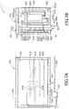
- FIGS. 7A and 7B are schematic views showing a configuration of a fuel cell module 1 according to the sixth embodiment.
- FIG. 7A is a lateral cross sectional view of a fuel cell module 1
- FIG. 7B is a front cross sectional view of the fuel cell module 1.
- the same components as those in the fifth embodiment are denoted by the same reference characters, and the explanation thereof will not be made.
- a copper plate 806 is placed on the low-performance wall insulator 802 on a cell stack 300 side. That is, the copper plate 806 is placed between the wall insulator 802 on the cell stack 300 side and the hydrodesulfurizer 100.
- the copper plate 806 is disposed so as to overlap the low-performance wall insulator 802.
- the copper plate 806 may be disposed so as to overlap also the high-performance wall insulators 804. Note that the copper plate 806 in the present embodiment equivalent to a high thermal conductive member.
- the hydrodesulfurizer 100 is in contact with also the copper plate 806. Having a good heat conductivity, the copper plate 806 has an action of conducting heat from a high temperature portion to a low temperature portion of the hydrodesulfurizer 100.
- the copper plate 806 is placed between the low-performance wall insulator 802 and the hydrodesulfurizer 100.
- the copper plate 806 conducts heat from a high temperature portion to a low temperature portion of the hydrodesulfurizer 100, and thus it is possible to homogenize the temperature distribution of the hydrodesulfurizer 100 even more.
- the temperature in the hydrodesulfurizer 100 can be kept at a temperature from 200 to 320°C at which the hydrodesulfurization catalysts perform the desulfurization effectively.
- a fuel cell module according to a seventh embodiment differs from that in the sixth embodiment in that the number of the partitioning portions forming the meandering channel in the air-preheating channel portion is one. Differences from the sixth embodiment will be explained below.
- FIGS. 8A and 8B are schematic views showing a configuration of a fuel cell module 1 according to the seventh embodiment.
- FIG. 8A is a lateral cross sectional view of a fuel cell module 1
- FIG. 8B is a front cross sectional view of the fuel cell module 1.
- the same components as those in the sixth embodiment are denoted by the same reference characters, and the explanation thereof will not be made.
- a partitioning portion 620 forms a space in a central portion 622 through which air streams.
- the space of the central portion 622 through which air streams is formed vertically upward of the air inlet pipe 601.
- clearances between both end portions of the partitioning portion 620 and the side wall of the air-preheating channel portion 600 are made the same at both end portions.
- the stream of air does not meander but is concentrated even more in the center of the cell stack 300 in the stacking direction, which causes the air to stream at high speed. Thus, a temperature rise of air streaming through the air-preheating channel portion 600 is inhibited.
- the space is provided in the central portion 622 of the partitioning portion 620, and the partitioning portion 620 is made to have left-right symmetry.
- the stream of air does not meander, heat exchange with the exhaust gas is inhibited, and a rise in temperature of the air is suppressed.
- the temperature in the hydrodesulfurizer 100 decreases as a whole.
- the temperature in the hydrodesulfurizer 100 can be kept at a temperature from 200 to 320°C at which the hydrodesulfurization catalysts perform the desulfurization more effectively.
- a fuel cell module according to an eighth embodiment differs from that in the sixth embodiment in that a first orifice and a first filter are disposed in the desulfurized fuel gas pipe. Differences from the sixth embodiment will be explained below.
- FIGS. 9A and 9B are schematic views showing a configuration of a fuel cell module 1 according to the eighth embodiment.
- FIG. 9A is a lateral cross sectional view of a fuel cell module 1
- FIG. 9B is a front cross sectional view of the fuel cell module 1.
- the same components as those in the sixth embodiment are denoted by the same reference characters, and the explanation thereof will not be made.
- a first orifice 120 and a first filter 122 are disposed in the desulfurized fuel gas pipe 102.
- the first orifice 120 is a throttling device and adjusts a stream through the desulfurized fuel gas pipe 102, making the inside of the desulfurized fuel gas pipe 102 at a low pressure.
- the first orifice 120 is equivalent to a first throttling device.
- the first filter 122 is made of a wire net, a blanket insulator, or the like.
- the first filter 122 is disposed between the outlet of the hydrodesulfurizer 100 and the first orifice 120.
- a controller 900 controls the driving of the fuel blower 106.
- the first orifice 120 suppresses the stream in the desulfurized fuel gas pipe 102, so as to reduce pulsation of the fuel gas by the fuel blower 106.
- the oxygen-containing gas passes the cell stack 300 and the reformer 200, and diffuses into the hydrodesulfurizer 100.
- the oxygen-containing gas is oxygen-containing gas remaining in the burner 400 and oxygen-containing gas entering the fuel cell module 1 through the air-preheating channel portion 600.
- the first orifice 120 inhibits the diffusion of oxygen into the hydrodesulfurizer 100. This inhibits mixing of the oxygen-containing gas into the hydrodesulfurizer 100.
- the hydrodesulfurizer 100 is used as it is reduced with hydrogen. Therefore, mixing of a lot of oxygen on every stop of the electric power generation leads to the degradation of the hydrodesulfurization catalysts.
- the first filter 122 absorbs powder of hydrodesulfurization catalysts that streams out together with the stream of desulfurized fuel gas. This inhibits a blockage of the first orifice 120 by the powder of the hydrodesulfurization catalysts.
- FIG. 10 is a diagram illustrating a flowchart of the drive control of the fuel blower 106.
- the controller 900 first stops the driving of the fuel blower 106 (step S10). This stops the supply of the fuel gas to the hydrodesulfurizer 100.
- the controller 900 determines whether a predetermined time period has elapsed from the stop of supplying the fuel gas (step S12). If the predetermined time period has elapsed (step S12: YES), the controller 900 resumes the driving of the fuel blower 106 and supplies the fuel gas to the hydrodesulfurizer 100 (step S14).
- the amount of one supply is, for example, the volume of the hydrodesulfurizer 100 and the reformer 200. If the amount of one supply is excessive, the hydrodesulfurizer 100 desulfurizes at a normal temperature, which increases the wearing out of the hydrodesulfurization catalysts.
- controller 900 supplies air to the burner 400 (step S16) and terminates the process.
- the fuel cell module 1 is prevented from filled with the fuel gas.
- the first orifice 120 is disposed in the desulfurized fuel gas pipe 102.
- the oxygen-containing gas is hard to be mixed in the hydrodesulfurizer 100, which inhibits the degradation of the hydrodesulfurization catalysts.
- the first orifice 120 reduces the pulsation of the fuel gas by the fuel blower 106 by suppressing the stream in the desulfurized fuel gas pipe 102.
- the first filter 122 is disposed between the outlet of the hydrodesulfurizer 100 and the first orifice 120. With this configuration, it is possible to inhibit the powder of the hydrodesulfurization catalysts from blocking the first orifice 120.
- the fuel gas is supplied to the hydrodesulfurizer 100 after a given time period elapses from the stop of supplying the fuel gas to the hydrodesulfurizer 100, the given time period being a time period in which oxygen diffuses to reach the hydrodesulfurizer 100.
- the given time period being a time period in which oxygen diffuses to reach the hydrodesulfurizer 100.
- a fuel cell module 1 according to a ninth embodiment differs from that in the eighth embodiment in that a water partition plate is placed in the water supply pipe to the reformer. Differences from the eighth embodiment will be explained below.
- FIGS. 11A and 11B are schematic views showing a configuration of a fuel cell module 1 according to the ninth embodiment.
- FIG. 11A is a lateral cross sectional view of a fuel cell module 1
- FIG. 11B is a front cross sectional view of the fuel cell module 1.
- the same components as those in the eighth embodiment are denoted by the same reference characters, and the explanation thereof will not be made.
- a water partition plate 1000 is disposed in the water supply pipe 202 so as to be closer to the reformer 200 than the confluence 203 of the desulfurized fuel gas pipe 102 and the water supply pipe 202.
- holes are formed in an upper portion of the water partition plate 1000, and no holes are formed in a lower portion thereof.
- liquid water is supplied from the water supply pipe 202. This prevents water from streaming into the reformer 200, and water is supplied to a horizontal portion of the desulfurized fuel gas pipe 102. With this supply, the desulfurized fuel gas pipe 102 and the first orifice 120 are each blocked by capillary force on the water.
- the water may be supplied after the supply of the certain amount of air illustrated in FIG. 10 .
- the water partition plate 1000 is disposed in the water supply pipe 202 so as to be closer to the reformer 200 than the confluence 203 of the desulfurized fuel gas pipe 102 and the water supply pipe 202.
- liquid water is inhibited from streaming to be closer to reformer 200 than the water partition plate 1000, and it is possible to store water in the desulfurized fuel gas pipe 102 efficiently. It is thereby possible to seal the outlet of the hydrodesulfurizer 100 and to prevent the oxidation of the hydrodesulfurization catalysts.
- the reformer 200 does not incline downward in a streaming direction of the water supply pipe 202, the water can be inhibited from streaming to be closer to the reformer 200 without using the water partition plate 1000.
- the inclination of the reformer 200 involves production variations.
- the production variations in the inclination of the reformer 200 are easy to be allowed, which can enhance a production yield.
- a fuel cell module according to a tenth embodiment differs from that in the ninth embodiment in that a recycling pipe is provided, the recycling pipe branching off from the hydrogen gas pipe and supplying the hydrogen-containing gas to the hydrodesulfurizer. Differences from the ninth embodiment will be explained below.
- FIG. 12 is a schematic views showing a configuration of a fuel cell module 1 according to the tenth embodiment.
- the left side figure in FIG. 12 is a lateral cross sectional view of a fuel cell module 1
- the right side figure in FIG. 12 is a front cross sectional view of the fuel cell module 1.
- the same components as those in the ninth embodiment are denoted by the same reference characters, and the explanation thereof will not be made.
- a recycling pipe 1100 branches off from the hydrogen gas pipe 204 and communicates with the fuel gas pipe 104.
- the reformer 200 supplies part of the hydrogen-containing gas to the hydrodesulfurizer 100 through the recycling pipe 1100.
- the recycling pipe 1100 merges with the fuel gas pipe 104 at a confluence 1102.
- a drain trap 1104 In the recycling pipe 1100, a drain trap 1104, a shut-off valve 1106, a second orifice 1108, and a second filter 1110 are disposed.
- the drain trap 1104 is configured to drain condensed water.
- the drain trap 1104 is disposed upstream of the second orifice 1108.
- the shut-off valve 1106 is configured to shut off the recycling pipe 1100.
- the second orifice 1108 is disposed upstream of the confluence 1102 and configured to inhibit fluctuations in the stream in the recycling pipe 1100.
- the second filter 1110 is disposed upstream of the second orifice 1108 and is made of a wire net, a blanket insulator, or the like.
- a third orifice 1112 and a third filter 1114 are disposed in the fuel gas pipe 104.
- the third orifice 1112 is disposed in the fuel gas pipe 104, upstream of the confluence 1102.
- the third filter 1114 is disposed in the fuel gas pipe 104, upstream of the third orifice 1112.
- the second orifice 1108 is equivalent to a second throttling device
- the third orifice 1112 equivalent to a third throttling device
- the hydrogen-containing gas generated by the reformer 200 is supplied to the hydrodesulfurizer 100 through the recycling pipe 1100. Therefore, without supplying hydrogen from the outside, common city gas and liquefied petroleum gas (LPG) can be used in the electric power generation.
- LPG liquefied petroleum gas
- the hydrogen-containing gas contains a surplus of steam. Therefore, when the hydrogen-containing gas is cooled, condensed water streams out from the reformer 200.
- the drain trap 1104 can discharge the condensed water that streams out from the reformer 200. In this case, the hydrogen-containing gas is not discharged.
- the shut-off valve 1106 closes immediately after start-up temperature rise where adequate hydrogen is not generated.
- the second orifice 1108 performs adjustment so that the fuel blower 106 does not suck the hydrogen-containing gas excessively.
- the second filter 1110 inhibits condensed water that is not completely discharged by the drain trap 1104, from blocking the second orifice 1108.
- the third orifice 1112 adjusts the amount of fuel gas sucked by the fuel blower 106.
- the third filter 1114 inhibits condensed water of vapor contained in city gas or LPG from blocking the third orifice 1112.
- the recycling pipe 1100 is provided, the recycling pipe 1100 branching off from the hydrogen gas pipe 204 and supplying the hydrogen-containing gas to the hydrodesulfurizer 100.
- common city gas and liquefied petroleum gas (LPG) can be used in the electric power generation without supplying hydrogen from the outside.
- the second orifice 1108 is disposed in the recycling pipe 1100
- the third orifice 1112 is disposed in the fuel gas pipe 104.
- the amount of the hydrogen-containing gas supplied to the cell stack 300 can be adjusted.
- the amount of hydrogen-containing gas supplied to the cell stack 300 can be increased immediately after start up where adequate hydrogen is not generated, or the like, and a start up temperature rise time period for which the hydrogen-containing gas is supplied to the burner 400 can be shortened.
- a fuel cell module according to an eleventh embodiment differs from that in the first reference examplein that a heater configured to heat the hydrodesulfurizer is provided. Differences from the first reference examplewill be explained below.
- FIGS. 13A and 13B are schematic views showing a configuration of a fuel cell module 1 according to the eleventh embodiment.
- FIG. 13A is a lateral cross sectional view of a fuel cell module 1
- FIG. 13B is a front cross sectional view of the fuel cell module 1.
- the same components as those in the first reference example are denoted by the same reference characters, and the explanation thereof will not be made.
- the configuration of the catalyst chambers 110, 112, and 114 of the hydrodesulfurizer 100 will not be explained for the purpose of the explanation of heaters 1116.
- the heaters 1116 are disposed so as to face portions upstream of the hydrodesulfurizer 100 and the air-preheating channel portion 600 where the temperature of the hydrodesulfurizer is liable to become low.
- the heaters 1116 are configured to heat the hydrodesulfurizer 100.
- the heaters 1116 are disposed so as to be in contact with the hydrodesulfurizer 100.
- the high-performance wall insulators 800, the low-performance wall insulator 802, and the copper plate 806 need not be disposed.
- the heaters 1116 are controlled by the controller 900 based on the temperatures of thermocouples placed inside the hydrodesulfurizer 100 (e.g., measured with the thermocouples illustrated in FIG. 1 ). With this configuration, it is possible to adjust the temperature in the hydrodesulfurizer 100 while measuring the interior temperature of the hydrodesulfurizer 100.
- the heaters 1116 configured to heat the hydrodesulfurizer 100 are provided.
- the heaters 1116 can perform heating so as to increase the temperature in the hydrodesulfurizer 100, whereby the temperature of the inside of the hydrodesulfurization catalysts can be adjusted. Therefore, it is possible to bring the temperature in the hydrodesulfurizer 100 closer to a temperature from 200 to 320°C at which the hydrodesulfurizer 100 can perform the desulfurization optimally.
- the electric power generation by the fuel cell module 1 can be performed efficiently even in early stages of operation.
Landscapes
- Chemical & Material Sciences (AREA)
- Engineering & Computer Science (AREA)
- Life Sciences & Earth Sciences (AREA)
- Manufacturing & Machinery (AREA)
- Sustainable Development (AREA)
- Sustainable Energy (AREA)
- Chemical Kinetics & Catalysis (AREA)
- Electrochemistry (AREA)
- General Chemical & Material Sciences (AREA)
- Combustion & Propulsion (AREA)
- Fuel Cell (AREA)
Claims (11)
- Brennstoffzellenmodul (1), aufweisend:eine Hydrodesulfurierungseinrichtung (100), die eingerichtet ist, Brennstoffgas mit einem Hydrodesulfurierungskatalysator zu entschwefeln;einen Reformer (200), der eingerichtet ist, ein Wasserstoff-haltiges Gas mithilfe des entschwefelten Brennstoffgases zu erzeugen;einen Zellenstapel (300), der durch Stapeln einer Vielzahl von Brennstoffzellen gebildet wird, wobei der Zellenstapel (300) eingerichtet ist, mithilfe des Wasserstoffhaltigen Gases und eines Sauerstoff-haltigen Gases elektrische Energie zu erzeugen;einen Auslasskanalabschnitt (500), der eingerichtet ist, das Wasserstoffhaltige Gas, das durch den Zellenstapel (300) nicht verbraucht wird, auszuleiten, und Abgas, das durch die Verbrennung des Sauerstoff-haltigen Gases erzeugt wird, auszuleiten;einen Luftvorerwärmungskanalabschnitt (600), der derart angeordnet ist, dass er neben dem Auslasskanalabschnitt ist, und der eingerichtet ist, das Sauerstoff-haltige Gas durch Wärmeaustausch mit dem Auslasskanalabschnitt (500) vorzuwärmen, wobei der Luftvorerwärmungskanalabschnitt (600) zwischen der Hydrodesulfurierungseinrichtung (100) und dem Zellenstapel (300) angeordnet ist;wobei der Luftvorerwärmungskanalabschnitt (600) einen ersten Luftvorerwärmungskanalabschnitt (600a) aufweist, der sich von einem unteren Abschnitt des Brennstoffzellenmoduls (1) bis zu einem oberen Abschnitt des Brennstoffzellenmoduls (1) erstreckt; und dadurch gekennzeichnet, dassein Isolator (802) eingerichtet ist, derart angeordnet zu sein, dass er mit der Hydrodesulfurierungseinrichtung (100) zwischen der Hydrodesulfurierungseinrichtung (100) und dem Luftvorerwärmungskanalabschnitt (600) in Kontakt ist,wobei die Hydrodesulfurierungseinrichtung (100) auf einer Seite des Luftvorerwärmungskanalabschnitts (600) angeordnet ist, und der Auslasskanalabschnitt (500) auf der anderen Seite des Luftvorerwärmungskanalabschnitts (600) angeordnet ist.
- Brennstoffzellenmodul (1) nach Anspruch 1, wobei zumindest ein Teil des Luftvorerwärmungskanalabschnitts (600) eine planare hohle Form besitzt, die eine Seite des Zellenstapels (300) über den Auslasskanalabschnitt (500) bedeckt, und einen Kanal aufweist, um eine Verteilung von Wärme, die an die Hydrodesulfurierungseinrichtung (100) geleitet wird, zu homogenisieren.
- Brennstoffzellenmodul (1) nach Anspruch 2, wobei der Kanal einen Raum (616, 618) aufweist, der in einem zentralen Abschnitt (616, 622) des Zellenstapels (300) gebildet ist, welcher derart eingerichtet ist, dass eine Menge des Sauerstoff-haltigen Gases, die entlang des zentralen Abschnitts (616, 622) des Zellenstapels geströmt wird, größer als eine Menge des Sauerstoff-haltigen Gases ist, das entlang von Endabschnitten des Zellenstapels (300) geströmt wird.
- Brennstoffzellenmodul (1) nach den Ansprüchen 2 und 3, wobei der Luftvorerwärmungskanalabschnitt (600) in einem unteren Abschnitt eines zentralen Abschnitts (616, 622) in der planaren hohlen Form einen Einlassabschnitt (601) aufweist, durch den das Sauerstoff-haltige Gas von außerhalb einströmt, und einen Kanal aufweist, der sich hin zu einem oberen Abschnitt schlängelt.
- Brennstoffzellenmodul (1) nach einem der Ansprüche 1 bis 4, ferner aufweisend:eine erste Drosselvorrichtung (120), die in einem Rohr (102) für entschwefeltes Brennstoffgas angeordnet ist, das mit der Hydrodesulfurierungseinrichtung (100) und dem Reformer (200) kommuniziert; undeinen ersten Filter (122), der zwischen der ersten Drosselvorrichtung (120) des Rohrs (102) für entschwefeltes Brennstoffgas und der Hydrodesulfurierungseinrichtung (100) angeordnet ist.
- Brennstoffzellenmodul (1) nach einem der Ansprüche 1 bis 5, wobei das Brennstoffgas durch einen Abschnitt, der nicht mit dem Hydrodesulfurierungskatalysator gefüllt ist, an die Hydrodesulfurierungseinrichtung (100) zugeführt oder aus dieser ausgeleitet wird.
- Brennstoffzellenmodul (1) nach einem der Ansprüche 1 bis 6, ferner aufweisend:ein Wasserzufuhrrohr (202), das eingerichtet ist, Wasser an den Reformer (200) zuzuführen;ein Rohr (102) für entschwefeltes Brennstoffgas, das eingerichtet ist, zwischen der Hydrodesulfurierungseinrichtung (100) und dem Reformer (200) eine Verbindung herzustellen, wobei das Rohr (102) für entschwefeltes Brennstoffgas mit dem Wasserzufuhrrohr (202) in einem Innenabschnitt des Reformers (200) zusammenläuft, wobeidas Rohr (102) für entschwefeltes Brennstoffgas eine Größe besitzt, die klein genug ist, um Wasser vermittels Kapillarkraft zu blockieren, und Wasser von dem Wasserzufuhrrohr (202) an das Rohr (102) für entschwefeltes Brennstoffgas zugeführt wird, um das Rohr (102) für entschwefeltes Brennstoffgas zu blockieren.
- Brennstoffzellenmodul (1) nach Anspruch 7, ferner aufweisend eine Wassertrennplatte (1000) mit einem Loch in einem oberen Abschnitt, die stromaufwärts des Innenabschnitts des Reformers (200) angeordnet ist.
- Brennstoffzellenmodul (1) nach einem der Ansprüche 1 bis 8, ferner aufweisend:ein Brennstoffgebläse (106), das eingerichtet ist, das Brennstoffgas durch das Brennstoffgasrohr (104) an die Hydrodesulfurierungseinrichtung (100) zuzuführen; undeinen Controller (900), der eingerichtet ist, das Brennstoffgebläse (106) anzusteuern, eine vorgegebene Menge des Brennstoffgases an die Hydrodesulfurierungseinrichtung (100) zuzuführen, nachdem eine vorgegebene Zeitspanne ab einem Stopp der Zufuhr des Brennstoffgases an die Hydrodesulfurierungseinrichtung (100) verstrichen ist.
- Brennstoffzellenmodul (1) nach einem der Ansprüche 1 bis 9, ferner aufweisend:ein Brennstoffgasrohr (104), das eingerichtet ist, das Brennstoffgas an die Hydrodesulfurierungseinrichtung (100) zuzuführen;ein Recyclingrohr (1100), das eingerichtet ist, einen Teil des Wasserstoffhaltigen Gases, das durch den Reformer (200) erzeugt wurde, an die Hydrodesulfurierungseinrichtung (100) zuzuführen, wobei das Recyclingrohr (1100) mit dem Brennstoffgasrohr (104) in dem Reformer (200) zusammenläuft;einen Geruchverschluss (1104), der eingerichtet ist, kondensiertes Wasser in dem Recyclingrohr (1100) auszuleiten;eine zweite Drosselvorrichtung (1108), die in dem Recyclingrohr (1100) stromabwärts des Reformers (200) angeordnet ist;einen zweiten Filter (1110), der in dem Recyclingrohr (1100) stromaufwärts der zweiten Drosselvorrichtung (1108) angeordnet ist;eine dritte Drosselvorrichtung (1112), die in dem Brennstoffgasrohr (104) stromaufwärts des Reformers (200) angeordnet ist; undeinen dritten Filter (1114), der in dem Brennstoffgasrohr (104) stromaufwärts der dritten Drosselvorrichtung (1112) angeordnet ist.
- Brennstoffzellenmodul (1) nach Anspruch 1, ferner aufweisend:eine Erwärmungseinrichtung (1116), die zwischen dem Luftvorerwärmungskanalabschnitt (600) und der Hydrodesulfurierungseinrichtung (100) angeordnet ist, wobeieine Temperatur der Erwärmungseinrichtung (1116) basierend auf zumindest einem oder mehr der Thermometer in der Hydrodesulfurierungseinrichtung (100) eingestellt wird.
Applications Claiming Priority (2)
| Application Number | Priority Date | Filing Date | Title |
|---|---|---|---|
| JP2016169802 | 2016-08-31 | ||
| JP2017102843A JP6982407B2 (ja) | 2016-08-31 | 2017-05-24 | 燃料電池モジュール |
Publications (2)
| Publication Number | Publication Date |
|---|---|
| EP3291348A1 EP3291348A1 (de) | 2018-03-07 |
| EP3291348B1 true EP3291348B1 (de) | 2020-08-12 |
Family
ID=59101373
Family Applications (1)
| Application Number | Title | Priority Date | Filing Date |
|---|---|---|---|
| EP17177242.9A Active EP3291348B1 (de) | 2016-08-31 | 2017-06-21 | Brennstoffzellenmodul |
Country Status (4)
| Country | Link |
|---|---|
| US (1) | US10770741B2 (de) |
| EP (1) | EP3291348B1 (de) |
| AU (1) | AU2017204268B2 (de) |
| CA (1) | CA2972196C (de) |
Families Citing this family (1)
| Publication number | Priority date | Publication date | Assignee | Title |
|---|---|---|---|---|
| US12458913B2 (en) | 2022-04-19 | 2025-11-04 | Cummins Inc. | Multi-stage filtration system for fuel cell hybrid propulsion system |
Family Cites Families (18)
| Publication number | Priority date | Publication date | Assignee | Title |
|---|---|---|---|---|
| US7063732B2 (en) * | 2003-07-28 | 2006-06-20 | Fuelcell Energy, Inc. | High-capacity sulfur adsorbent bed and gas desulfurization method |
| EP2020696B1 (de) * | 2007-07-20 | 2013-10-16 | NGK Insulators, Ltd. | Reaktor |
| TW201429039A (zh) | 2008-05-14 | 2014-07-16 | Nippon Oil Corp | 燃料電池系統 |
| WO2010058749A1 (ja) * | 2008-11-18 | 2010-05-27 | 東京瓦斯株式会社 | Mcfc発電システムとその運転方法 |
| US8304122B2 (en) * | 2009-02-06 | 2012-11-06 | Protonex Technology Corporation | Solid oxide fuel cell systems with hot zones having improved reactant distribution |
| US8459416B2 (en) | 2009-07-17 | 2013-06-11 | Shimano, Inc. | Quick-release apparatus for a bicycle hydraulic caliper brake |
| JP5588689B2 (ja) | 2010-02-01 | 2014-09-10 | 大阪瓦斯株式会社 | 固体酸化物形燃料電池 |
| US20130017458A1 (en) * | 2010-03-30 | 2013-01-17 | Panasonic Corporation | Fuel cell system and operation method thereof |
| JP5584507B2 (ja) | 2010-03-31 | 2014-09-03 | 大阪瓦斯株式会社 | 固体酸化物形燃料電池システム |
| EP2840061B1 (de) * | 2012-04-19 | 2021-09-15 | Panasonic Intellectual Property Management Co., Ltd. | Vorrichtung zur wasserstoffproduktion und brennstoffzellensystem |
| JP6098795B2 (ja) | 2012-11-29 | 2017-03-22 | パナソニックIpマネジメント株式会社 | 固体酸化物形燃料電池システム |
| JP5866546B2 (ja) * | 2013-04-16 | 2016-02-17 | パナソニックIpマネジメント株式会社 | 燃料電池システム |
| JP6111904B2 (ja) | 2013-07-03 | 2017-04-12 | 株式会社デンソー | 燃料電池装置 |
| US10461341B2 (en) * | 2013-12-19 | 2019-10-29 | Panasonic Corporation | Fuel cell system |
| JP6311865B2 (ja) * | 2014-02-03 | 2018-04-18 | Toto株式会社 | 固体酸化物型燃料電池装置 |
| JP6396182B2 (ja) | 2014-11-12 | 2018-09-26 | 東芝燃料電池システム株式会社 | 燃料電池システム |
| US10090548B2 (en) | 2014-11-26 | 2018-10-02 | Panasonic Intellectual Property Management Co., Ltd. | Fuel cell system |
| US20160213862A1 (en) | 2015-01-27 | 2016-07-28 | Becton, Dickinson And Company | Iv set having an air stop membrane |
-
2017
- 2017-06-21 US US15/628,783 patent/US10770741B2/en active Active
- 2017-06-21 EP EP17177242.9A patent/EP3291348B1/de active Active
- 2017-06-23 AU AU2017204268A patent/AU2017204268B2/en not_active Ceased
- 2017-06-29 CA CA2972196A patent/CA2972196C/en active Active
Non-Patent Citations (1)
| Title |
|---|
| None * |
Also Published As
| Publication number | Publication date |
|---|---|
| CA2972196A1 (en) | 2018-02-28 |
| AU2017204268A1 (en) | 2018-03-15 |
| CA2972196C (en) | 2020-02-18 |
| EP3291348A1 (de) | 2018-03-07 |
| AU2017204268B2 (en) | 2018-07-26 |
| US10770741B2 (en) | 2020-09-08 |
| US20180062191A1 (en) | 2018-03-01 |
Similar Documents
| Publication | Publication Date | Title |
|---|---|---|
| EP2985830B1 (de) | Brennstoffzellensystem | |
| JP4906242B2 (ja) | 燃料電池の稼動停止方法 | |
| JP6488416B2 (ja) | 燃料電池システム | |
| JP5643712B2 (ja) | 燃料電池モジュール | |
| CN104205456A (zh) | 固体氧化物型燃料电池系统 | |
| WO2011108264A1 (ja) | 水素生成装置および燃料電池発電システム | |
| EP2950377A1 (de) | Brennstoffzelle | |
| JP6405211B2 (ja) | 燃料電池システム | |
| EP3291348B1 (de) | Brennstoffzellenmodul | |
| KR101929801B1 (ko) | 연료 전지 모듈 | |
| JP5895169B2 (ja) | 水素生成装置 | |
| JP5807167B2 (ja) | 水素生成装置 | |
| KR102111393B1 (ko) | 연료 전지 시스템, 및 연료 전지 모듈 | |
| JP5948605B2 (ja) | 水素生成装置 | |
| JP2012221934A (ja) | 燃料電池モジュール | |
| JP2005255458A (ja) | 水素生成装置及び燃料電池システム | |
| JP5140361B2 (ja) | 燃料電池用改質装置 | |
| JP2008198485A (ja) | 燃料電池システム | |
| JP2008117547A (ja) | 燃料電池 | |
| JP6757664B2 (ja) | 燃料電池システム | |
| JP6205581B2 (ja) | 水素生成装置及びそれを用いた燃料電池システム | |
| JP2017183135A (ja) | 固体酸化物形燃料電池装置 | |
| JP2016222497A (ja) | 水素生成装置及びそれを用いた燃料電池システム | |
| JP2017039626A (ja) | 水素生成装置 | |
| JP2015133201A (ja) | 燃料電池システム |
Legal Events
| Date | Code | Title | Description |
|---|---|---|---|
| PUAI | Public reference made under article 153(3) epc to a published international application that has entered the european phase |
Free format text: ORIGINAL CODE: 0009012 |
|
| STAA | Information on the status of an ep patent application or granted ep patent |
Free format text: STATUS: REQUEST FOR EXAMINATION WAS MADE |
|
| 17P | Request for examination filed |
Effective date: 20170621 |
|
| AK | Designated contracting states |
Kind code of ref document: A1 Designated state(s): AL AT BE BG CH CY CZ DE DK EE ES FI FR GB GR HR HU IE IS IT LI LT LU LV MC MK MT NL NO PL PT RO RS SE SI SK SM TR |
|
| AX | Request for extension of the european patent |
Extension state: BA ME |
|
| STAA | Information on the status of an ep patent application or granted ep patent |
Free format text: STATUS: EXAMINATION IS IN PROGRESS |
|
| 17Q | First examination report despatched |
Effective date: 20181011 |
|
| RAP1 | Party data changed (applicant data changed or rights of an application transferred) |
Owner name: TOSHIBA ENERGY SYSTEMS & SOLUTIONS CORPORATION |
|
| RAP1 | Party data changed (applicant data changed or rights of an application transferred) |
Owner name: KABUSHIKI KAISHA TOSHIBA Owner name: TOSHIBA ENERGY SYSTEMS & SOLUTIONS CORPORATION |
|
| GRAP | Despatch of communication of intention to grant a patent |
Free format text: ORIGINAL CODE: EPIDOSNIGR1 |
|
| STAA | Information on the status of an ep patent application or granted ep patent |
Free format text: STATUS: GRANT OF PATENT IS INTENDED |
|
| RIC1 | Information provided on ipc code assigned before grant |
Ipc: H01M 8/0662 20160101ALI20200204BHEP Ipc: H01M 8/124 20160101ALN20200204BHEP Ipc: H01M 8/04014 20160101ALI20200204BHEP Ipc: H01M 8/0612 20160101AFI20200204BHEP |
|
| INTG | Intention to grant announced |
Effective date: 20200302 |
|
| GRAS | Grant fee paid |
Free format text: ORIGINAL CODE: EPIDOSNIGR3 |
|
| GRAA | (expected) grant |
Free format text: ORIGINAL CODE: 0009210 |
|
| STAA | Information on the status of an ep patent application or granted ep patent |
Free format text: STATUS: THE PATENT HAS BEEN GRANTED |
|
| AK | Designated contracting states |
Kind code of ref document: B1 Designated state(s): AL AT BE BG CH CY CZ DE DK EE ES FI FR GB GR HR HU IE IS IT LI LT LU LV MC MK MT NL NO PL PT RO RS SE SI SK SM TR |
|
| REG | Reference to a national code |
Ref country code: CH Ref legal event code: EP |
|
| REG | Reference to a national code |
Ref country code: IE Ref legal event code: FG4D |
|
| REG | Reference to a national code |
Ref country code: DE Ref legal event code: R096 Ref document number: 602017021435 Country of ref document: DE |
|
| REG | Reference to a national code |
Ref country code: AT Ref legal event code: REF Ref document number: 1302439 Country of ref document: AT Kind code of ref document: T Effective date: 20200915 Ref country code: CH Ref legal event code: NV Representative=s name: SCHNEIDER FELDMANN AG PATENT- UND MARKENANWAEL, CH |
|
| REG | Reference to a national code |
Ref country code: FI Ref legal event code: FGE |
|
| REG | Reference to a national code |
Ref country code: CH Ref legal event code: PFA Owner name: KABUSHIKI KAISHA TOSHIBA, JP Free format text: FORMER OWNER: KABUSHIKI KAISHA TOSHIBA, JP |
|
| REG | Reference to a national code |
Ref country code: DK Ref legal event code: T3 Effective date: 20201109 |
|
| REG | Reference to a national code |
Ref country code: LT Ref legal event code: MG4D |
|
| REG | Reference to a national code |
Ref country code: NL Ref legal event code: MP Effective date: 20200812 |
|
| PG25 | Lapsed in a contracting state [announced via postgrant information from national office to epo] |
Ref country code: BG Free format text: LAPSE BECAUSE OF FAILURE TO SUBMIT A TRANSLATION OF THE DESCRIPTION OR TO PAY THE FEE WITHIN THE PRESCRIBED TIME-LIMIT Effective date: 20201112 Ref country code: SE Free format text: LAPSE BECAUSE OF FAILURE TO SUBMIT A TRANSLATION OF THE DESCRIPTION OR TO PAY THE FEE WITHIN THE PRESCRIBED TIME-LIMIT Effective date: 20200812 Ref country code: GR Free format text: LAPSE BECAUSE OF FAILURE TO SUBMIT A TRANSLATION OF THE DESCRIPTION OR TO PAY THE FEE WITHIN THE PRESCRIBED TIME-LIMIT Effective date: 20201113 Ref country code: LT Free format text: LAPSE BECAUSE OF FAILURE TO SUBMIT A TRANSLATION OF THE DESCRIPTION OR TO PAY THE FEE WITHIN THE PRESCRIBED TIME-LIMIT Effective date: 20200812 Ref country code: HR Free format text: LAPSE BECAUSE OF FAILURE TO SUBMIT A TRANSLATION OF THE DESCRIPTION OR TO PAY THE FEE WITHIN THE PRESCRIBED TIME-LIMIT Effective date: 20200812 Ref country code: NO Free format text: LAPSE BECAUSE OF FAILURE TO SUBMIT A TRANSLATION OF THE DESCRIPTION OR TO PAY THE FEE WITHIN THE PRESCRIBED TIME-LIMIT Effective date: 20201112 |
|
| REG | Reference to a national code |
Ref country code: AT Ref legal event code: MK05 Ref document number: 1302439 Country of ref document: AT Kind code of ref document: T Effective date: 20200812 |
|
| PG25 | Lapsed in a contracting state [announced via postgrant information from national office to epo] |
Ref country code: RS Free format text: LAPSE BECAUSE OF FAILURE TO SUBMIT A TRANSLATION OF THE DESCRIPTION OR TO PAY THE FEE WITHIN THE PRESCRIBED TIME-LIMIT Effective date: 20200812 Ref country code: NL Free format text: LAPSE BECAUSE OF FAILURE TO SUBMIT A TRANSLATION OF THE DESCRIPTION OR TO PAY THE FEE WITHIN THE PRESCRIBED TIME-LIMIT Effective date: 20200812 Ref country code: PL Free format text: LAPSE BECAUSE OF FAILURE TO SUBMIT A TRANSLATION OF THE DESCRIPTION OR TO PAY THE FEE WITHIN THE PRESCRIBED TIME-LIMIT Effective date: 20200812 Ref country code: LV Free format text: LAPSE BECAUSE OF FAILURE TO SUBMIT A TRANSLATION OF THE DESCRIPTION OR TO PAY THE FEE WITHIN THE PRESCRIBED TIME-LIMIT Effective date: 20200812 Ref country code: IS Free format text: LAPSE BECAUSE OF FAILURE TO SUBMIT A TRANSLATION OF THE DESCRIPTION OR TO PAY THE FEE WITHIN THE PRESCRIBED TIME-LIMIT Effective date: 20201212 |
|
| PG25 | Lapsed in a contracting state [announced via postgrant information from national office to epo] |
Ref country code: EE Free format text: LAPSE BECAUSE OF FAILURE TO SUBMIT A TRANSLATION OF THE DESCRIPTION OR TO PAY THE FEE WITHIN THE PRESCRIBED TIME-LIMIT Effective date: 20200812 Ref country code: SM Free format text: LAPSE BECAUSE OF FAILURE TO SUBMIT A TRANSLATION OF THE DESCRIPTION OR TO PAY THE FEE WITHIN THE PRESCRIBED TIME-LIMIT Effective date: 20200812 Ref country code: CZ Free format text: LAPSE BECAUSE OF FAILURE TO SUBMIT A TRANSLATION OF THE DESCRIPTION OR TO PAY THE FEE WITHIN THE PRESCRIBED TIME-LIMIT Effective date: 20200812 Ref country code: RO Free format text: LAPSE BECAUSE OF FAILURE TO SUBMIT A TRANSLATION OF THE DESCRIPTION OR TO PAY THE FEE WITHIN THE PRESCRIBED TIME-LIMIT Effective date: 20200812 |
|
| REG | Reference to a national code |
Ref country code: DE Ref legal event code: R097 Ref document number: 602017021435 Country of ref document: DE |
|
| PG25 | Lapsed in a contracting state [announced via postgrant information from national office to epo] |
Ref country code: AL Free format text: LAPSE BECAUSE OF FAILURE TO SUBMIT A TRANSLATION OF THE DESCRIPTION OR TO PAY THE FEE WITHIN THE PRESCRIBED TIME-LIMIT Effective date: 20200812 Ref country code: AT Free format text: LAPSE BECAUSE OF FAILURE TO SUBMIT A TRANSLATION OF THE DESCRIPTION OR TO PAY THE FEE WITHIN THE PRESCRIBED TIME-LIMIT Effective date: 20200812 Ref country code: ES Free format text: LAPSE BECAUSE OF FAILURE TO SUBMIT A TRANSLATION OF THE DESCRIPTION OR TO PAY THE FEE WITHIN THE PRESCRIBED TIME-LIMIT Effective date: 20200812 |
|
| PLBE | No opposition filed within time limit |
Free format text: ORIGINAL CODE: 0009261 |
|
| STAA | Information on the status of an ep patent application or granted ep patent |
Free format text: STATUS: NO OPPOSITION FILED WITHIN TIME LIMIT |
|
| PG25 | Lapsed in a contracting state [announced via postgrant information from national office to epo] |
Ref country code: SK Free format text: LAPSE BECAUSE OF FAILURE TO SUBMIT A TRANSLATION OF THE DESCRIPTION OR TO PAY THE FEE WITHIN THE PRESCRIBED TIME-LIMIT Effective date: 20200812 |
|
| 26N | No opposition filed |
Effective date: 20210514 |
|
| PG25 | Lapsed in a contracting state [announced via postgrant information from national office to epo] |
Ref country code: IT Free format text: LAPSE BECAUSE OF FAILURE TO SUBMIT A TRANSLATION OF THE DESCRIPTION OR TO PAY THE FEE WITHIN THE PRESCRIBED TIME-LIMIT Effective date: 20200812 |
|
| PG25 | Lapsed in a contracting state [announced via postgrant information from national office to epo] |
Ref country code: SI Free format text: LAPSE BECAUSE OF FAILURE TO SUBMIT A TRANSLATION OF THE DESCRIPTION OR TO PAY THE FEE WITHIN THE PRESCRIBED TIME-LIMIT Effective date: 20200812 |
|
| PG25 | Lapsed in a contracting state [announced via postgrant information from national office to epo] |
Ref country code: MC Free format text: LAPSE BECAUSE OF FAILURE TO SUBMIT A TRANSLATION OF THE DESCRIPTION OR TO PAY THE FEE WITHIN THE PRESCRIBED TIME-LIMIT Effective date: 20200812 |
|
| REG | Reference to a national code |
Ref country code: BE Ref legal event code: MM Effective date: 20210630 |
|
| PG25 | Lapsed in a contracting state [announced via postgrant information from national office to epo] |
Ref country code: LU Free format text: LAPSE BECAUSE OF NON-PAYMENT OF DUE FEES Effective date: 20210621 |
|
| PG25 | Lapsed in a contracting state [announced via postgrant information from national office to epo] |
Ref country code: IE Free format text: LAPSE BECAUSE OF NON-PAYMENT OF DUE FEES Effective date: 20210621 |
|
| PG25 | Lapsed in a contracting state [announced via postgrant information from national office to epo] |
Ref country code: FR Free format text: LAPSE BECAUSE OF NON-PAYMENT OF DUE FEES Effective date: 20210630 |
|
| PG25 | Lapsed in a contracting state [announced via postgrant information from national office to epo] |
Ref country code: BE Free format text: LAPSE BECAUSE OF NON-PAYMENT OF DUE FEES Effective date: 20210630 |
|
| PG25 | Lapsed in a contracting state [announced via postgrant information from national office to epo] |
Ref country code: PT Free format text: LAPSE BECAUSE OF FAILURE TO SUBMIT A TRANSLATION OF THE DESCRIPTION OR TO PAY THE FEE WITHIN THE PRESCRIBED TIME-LIMIT Effective date: 20201214 |
|
| PG25 | Lapsed in a contracting state [announced via postgrant information from national office to epo] |
Ref country code: HU Free format text: LAPSE BECAUSE OF FAILURE TO SUBMIT A TRANSLATION OF THE DESCRIPTION OR TO PAY THE FEE WITHIN THE PRESCRIBED TIME-LIMIT; INVALID AB INITIO Effective date: 20170621 |
|
| PG25 | Lapsed in a contracting state [announced via postgrant information from national office to epo] |
Ref country code: CY Free format text: LAPSE BECAUSE OF FAILURE TO SUBMIT A TRANSLATION OF THE DESCRIPTION OR TO PAY THE FEE WITHIN THE PRESCRIBED TIME-LIMIT Effective date: 20200812 |
|
| PGFP | Annual fee paid to national office [announced via postgrant information from national office to epo] |
Ref country code: DK Payment date: 20230613 Year of fee payment: 7 Ref country code: DE Payment date: 20230425 Year of fee payment: 7 |
|
| PGFP | Annual fee paid to national office [announced via postgrant information from national office to epo] |
Ref country code: FI Payment date: 20230615 Year of fee payment: 7 |
|
| PGFP | Annual fee paid to national office [announced via postgrant information from national office to epo] |
Ref country code: GB Payment date: 20230427 Year of fee payment: 7 Ref country code: CH Payment date: 20230702 Year of fee payment: 7 |
|
| PG25 | Lapsed in a contracting state [announced via postgrant information from national office to epo] |
Ref country code: MK Free format text: LAPSE BECAUSE OF FAILURE TO SUBMIT A TRANSLATION OF THE DESCRIPTION OR TO PAY THE FEE WITHIN THE PRESCRIBED TIME-LIMIT Effective date: 20200812 |
|
| PG25 | Lapsed in a contracting state [announced via postgrant information from national office to epo] |
Ref country code: MT Free format text: LAPSE BECAUSE OF FAILURE TO SUBMIT A TRANSLATION OF THE DESCRIPTION OR TO PAY THE FEE WITHIN THE PRESCRIBED TIME-LIMIT Effective date: 20200812 |
|
| REG | Reference to a national code |
Ref country code: DE Ref legal event code: R119 Ref document number: 602017021435 Country of ref document: DE |
|
| PG25 | Lapsed in a contracting state [announced via postgrant information from national office to epo] |
Ref country code: FI Free format text: LAPSE BECAUSE OF NON-PAYMENT OF DUE FEES Effective date: 20240621 |
|
| REG | Reference to a national code |
Ref country code: DK Ref legal event code: EBP Effective date: 20240630 |
|
| PG25 | Lapsed in a contracting state [announced via postgrant information from national office to epo] |
Ref country code: FI Free format text: LAPSE BECAUSE OF NON-PAYMENT OF DUE FEES Effective date: 20240621 |
|
| REG | Reference to a national code |
Ref country code: CH Ref legal event code: PL |
|
| GBPC | Gb: european patent ceased through non-payment of renewal fee |
Effective date: 20240621 |
|
| PG25 | Lapsed in a contracting state [announced via postgrant information from national office to epo] |
Ref country code: DE Free format text: LAPSE BECAUSE OF NON-PAYMENT OF DUE FEES Effective date: 20250101 |
|
| PG25 | Lapsed in a contracting state [announced via postgrant information from national office to epo] |
Ref country code: CH Free format text: LAPSE BECAUSE OF NON-PAYMENT OF DUE FEES Effective date: 20240630 |
|
| PG25 | Lapsed in a contracting state [announced via postgrant information from national office to epo] |
Ref country code: GB Free format text: LAPSE BECAUSE OF NON-PAYMENT OF DUE FEES Effective date: 20240621 |
|
| PG25 | Lapsed in a contracting state [announced via postgrant information from national office to epo] |
Ref country code: DK Free format text: LAPSE BECAUSE OF NON-PAYMENT OF DUE FEES Effective date: 20240630 |
|
| PG25 | Lapsed in a contracting state [announced via postgrant information from national office to epo] |
Ref country code: TR Free format text: LAPSE BECAUSE OF FAILURE TO SUBMIT A TRANSLATION OF THE DESCRIPTION OR TO PAY THE FEE WITHIN THE PRESCRIBED TIME-LIMIT Effective date: 20200812 |