EP3291380B1 - Verbinderanordnung mit einer verriegelungsanordnung - Google Patents
Verbinderanordnung mit einer verriegelungsanordnung Download PDFInfo
- Publication number
- EP3291380B1 EP3291380B1 EP16186399.8A EP16186399A EP3291380B1 EP 3291380 B1 EP3291380 B1 EP 3291380B1 EP 16186399 A EP16186399 A EP 16186399A EP 3291380 B1 EP3291380 B1 EP 3291380B1
- Authority
- EP
- European Patent Office
- Prior art keywords
- connector
- latching
- fixation sleeve
- fixation
- connector body
- Prior art date
- Legal status (The legal status is an assumption and is not a legal conclusion. Google has not performed a legal analysis and makes no representation as to the accuracy of the status listed.)
- Active
Links
Images


Classifications
-
- H—ELECTRICITY
- H01—ELECTRIC ELEMENTS
- H01R—ELECTRICALLY-CONDUCTIVE CONNECTIONS; STRUCTURAL ASSOCIATIONS OF A PLURALITY OF MUTUALLY-INSULATED ELECTRICAL CONNECTING ELEMENTS; COUPLING DEVICES; CURRENT COLLECTORS
- H01R13/00—Details of coupling devices of the kinds covered by groups H01R12/70 or H01R24/00 - H01R33/00
- H01R13/62—Means for facilitating engagement or disengagement of coupling parts or for holding them in engagement
- H01R13/622—Screw-ring or screw-casing
-
- H—ELECTRICITY
- H01—ELECTRIC ELEMENTS
- H01R—ELECTRICALLY-CONDUCTIVE CONNECTIONS; STRUCTURAL ASSOCIATIONS OF A PLURALITY OF MUTUALLY-INSULATED ELECTRICAL CONNECTING ELEMENTS; COUPLING DEVICES; CURRENT COLLECTORS
- H01R13/00—Details of coupling devices of the kinds covered by groups H01R12/70 or H01R24/00 - H01R33/00
- H01R13/62—Means for facilitating engagement or disengagement of coupling parts or for holding them in engagement
- H01R13/625—Casing or ring with bayonet engagement
-
- H—ELECTRICITY
- H01—ELECTRIC ELEMENTS
- H01R—ELECTRICALLY-CONDUCTIVE CONNECTIONS; STRUCTURAL ASSOCIATIONS OF A PLURALITY OF MUTUALLY-INSULATED ELECTRICAL CONNECTING ELEMENTS; COUPLING DEVICES; CURRENT COLLECTORS
- H01R13/00—Details of coupling devices of the kinds covered by groups H01R12/70 or H01R24/00 - H01R33/00
- H01R13/62—Means for facilitating engagement or disengagement of coupling parts or for holding them in engagement
- H01R13/627—Snap or like fastening
- H01R13/6276—Snap or like fastening comprising one or more balls engaging in a hole or a groove
-
- H—ELECTRICITY
- H01—ELECTRIC ELEMENTS
- H01R—ELECTRICALLY-CONDUCTIVE CONNECTIONS; STRUCTURAL ASSOCIATIONS OF A PLURALITY OF MUTUALLY-INSULATED ELECTRICAL CONNECTING ELEMENTS; COUPLING DEVICES; CURRENT COLLECTORS
- H01R13/00—Details of coupling devices of the kinds covered by groups H01R12/70 or H01R24/00 - H01R33/00
- H01R13/64—Means for preventing incorrect coupling
Definitions
- the invention relates to a connector assembly according to claim 1 for a connection with a complementary connector comprising a connector body and a fixation sleeve, the fixation sleeve being held rotatable relative to the connector body on the connector body and the connector body being at least partially arranged inside the fixation sleeve, the connector assembly further comprising at least one fixation element for engagement with the complementary connector, wherein the connector assembly comprises a latching arrangement providing at least two latching positions, wherein, in a first of the at least two latching positions, the fixation sleeve is in a different angular position than in a second of the at least two latching positions relative to the connector body, and wherein the fixation sleeve is coupled to the connector body via at least one drive system which is adapted to convert a rotation of the fixation sleeve into an axial movement of the connector body.
- Connector assemblies of the above-mentioned type are known in the prior art. They can be used to securely fixate a connector assembly to a complementary connector.
- the fixation sleeve which comprises at least one fixation element, may be used to fixate or lock the connector assembly to a complementary connector by rotating the sleeve relatively to the connector body. It may be required to adjust the fixation sleeve in a certain rotational position with respect to the connector body. This may for example be necessary in order to facilitate the mating of the connector assembly with the complementary connector and/or to provide a secure fixation between the connector assembly and a complementary connector.
- a connector that can be fixated to a mating connector is known from WO 2007/071968 A2 .
- a linearly slidable collar is adapted to push a ball into a corresponding groove of a mating connector in order to fixate both connectors with each other.
- a rotation guide with different connection positions is known from EP 0 620 615 A2 .
- An inner groove in a rotatable sleeve of the connector can interact with a corresponding pin on a complementary connector. Upon rotation of the sleeve, the connector is drawn against the complementary connector.
- Document WO 90/15282 A1 relates to an axial locking device which allows locking of two connectors due to an axial movement of an external sleeve on one of the connectors.
- a connector with a drive system that converts a rotational movement into a longitudinal movement is known from US 4 629 272 A . From GB 2 373 380 A , a push-pull quick connect connector is known.
- the at least one drive system comprises three cam tracks and three pin members, wherein the cam tracks are arranged in an outer circumference of the connector body and at least partially coil around an axis of rotation of the fixation sleeve, and wherein the three pin members project from an inner circumference of the fixation sleeve into the cam tracks in the connector body in an assembled state of the connector assembly.
- the latching arrangement allows to define at least two different rotational positions between the fixation sleeve and the connector body.
- the first latching position may be a position in which the fixation sleeve is aligned with the connector body such that mating with a complementary connector is possible.
- the second latching position may be a position in which mating is not possible, but in which the fixation element is engaged with the complementary connector.
- the connector body may be adapted to carry at least one element, such as an electric contact for being brought into contact with at least one complementary electric contact of the complementary connector. However, it is also possible that the connector body does not provide electric contacts, but other elements.
- the fixation sleeve is preferably coupled to the connector body such that it is rotatable around an axis of rotation. This axis of rotation may also be parallel to a mating direction of the connector assembly. Preferably, the mating direction is defined by the fixation sleeve, which may be arranged at a front side of the connector assembly in an assembled state.
- the drive system allows to automatically move the connector body along the axial direction when the fixation sleeve is moved between the latching positions.
- the arrangement with the pin members and the cam tracks provide a simple but reliable solution for a drive system.
- the latching arrangement may be adapted to latch the fixation sleeve to the connector body in the at least two aforementioned latching positions.
- the latching arrangement may be adapted to maintain a latching position as long as a moment of force on the fixation sleeve does not exceed a pre-assigned value.
- the angular difference between two latching positions is between 85 and 95 degrees, most preferably, 90 degrees.
- the latching arrangement may be adapted to provide an audible response when a latching position is reached.
- the latching arrangement may be adapted to provide a clicking noise when a latching position is reached.
- the at least one latching arrangement may comprise at least one elastically deformable latching member on the connector body and at least two receiving recesses in the fixation sleeve for the at least one latching member, or vice versa. Additional or in the alternative, the at least one latching arrangement may comprise at least two elastically deformable latching members on the connector body and at least one receiving recess in the fixation sleeve for the at least one latching member or vice versa. When a latching position is reached, the at least one deformable latching member may snap into the corresponding receiving recess.
- the latching position is reached and a rotational movement of the fixation sleeve is preferably prohibited as long as a moment of force on the fixation sleeve does not exceed a pre-assigned value.
- the latching member may produce a noise which may serve as an audible response that the latching position is reached.
- the at least one latching arrangement comprises four elastically deformable latching members and four receiving recesses.
- the elastically deformable latching members and the receiving recesses are preferably equally spaced around the axis of rotation.
- the at least one elastically deformable latching member may comprise a compression spring and a ball-shaped latching element.
- the ball-shaped latching element may be arranged at one end of the compression spring.
- the compression spring is fixated to the outer circumference of the connector body such that the ball-shaped latching element may be in contact with an inner circumference of the fixation sleeve.
- the compression spring may be at least partially housed in a recess in the outer circumference of the connector body.
- the ball-shaped latching element may snap into a receiving recess when one of the latching positions is reached.
- the ball-shaped latching element may be in permanent contact with an inner wall of the fixation sleeve.
- the ball-shaped latching elements may function as a ball bearing for the rotational movement of the fixation sleeve around the connector body.
- the at least one receiving recess may be formed as a groove which extends parallel to the axial direction.
- the term "axial direction" refers to the axis of rotation of the fixation sleeve with respect to the connector body.
- the connector body may be arranged in different axial positions relative to the fixation sleeve.
- the connector body in the second latching position, the connector body may be arranged further away from the fixation element compared to the second latching position. This may improve the connection of elements in the connector body with complementary elements in the complementary connector.
- the connector body in the first latching position, the connector body may be arranged in a pre-connection position in which it is at least partially drawn back from a front end of the connector assembly, which may be defined by the position of the at least one fixation element of the fixation sleeve.
- the connector body In the second latching position, the connector body may be arranged in a connection position, in which it is arranged closer to the fixation element.
- the connector assembly may be plugged together with a complementary connector when the connector body is arranged in the pre-connection position. Elements in the connector body may then still be unconnected or connected with a low connection pressure to elements of the complementary connector. The connector body may afterwards be brought into a different axial position, the connection position, in which elements in the connector body may be connected to complementary elements in the complementary connector and/or being pressed against said elements.
- the drive system is arranged partially in the fixation sleeve and partially in the connector body.
- the three cam tracks and the three pin members are preferably equally spaced around the axis of rotation.
- the fixation sleeve may be provided with at least one first alignment feature and the connector body may be provided with at least one second alignment feature, wherein, in the first latching position, the first and second alignment features are aligned such that at least one uninterrupted insertion path for at least one counter alignment feature of the complementary connector extends parallel to the axis of rotation of the fixation sleeve. Consequently, in the first latching position, the connector assembly is ready for being connected to a complementary connector.
- the at least one latching arrangement according to the invention may facilitate the alignment of the first and second alignment features towards each other because it provides the latching positions and is adapted to keep the fixation sleeve to the connector body in the first latching position.
- the at least one first alignment feature is arranged on an inner circumference of the fixation sleeve and the at least one second alignment feature is arranged on an inner circumference of the connector body.
- the alignment features may be formed by recesses and/or elevated regions in the circumferences of the connector body and the fixation sleeve.
- the at least one first alignment feature of the fixation sleeve may be defined by the at least one fixation element.
- the at least one fixation element of the fixation sleeve may also function as at least one first alignment feature.
- the at least one first alignment feature of the fixation sleeve may extend further in a radial direction than the corresponding at least one second alignment feature of the connector body. This may allow the at least one first alignment feature to pass by a counter fixation element of a complementary connector during mating of the connector assembly to said complementary connector.
- the at least one first alignment feature and the at least one second alignment feature are shaped complementary to complimentary alignment features of a receptacle or complementary connector according to the MIL-DTL 38999 series IV connector.
- the at least one first and the at least one second alignment feature may be aligned such that the at least one insertion part is interrupted. In this position, mating of the connector assembly with a complementary connector may be prevented. Additionally, if the connector assembly is mated with a complementary connector, the fixation sleeve with its at least one fixation element may be rotated in the second latching position such that the at least one fixation element is engaged with a counter fixation element and is positively locked with it, such that unmating of the connector assembly and the complementary connector is prevented.
- the at least one first alignment feature is defined by or identical to the at least one fixation element
- the first alignment feature is not aligned to the second alignment feature along the axis of rotation anymore and the insertion path is interrupted.
- the at least one first alignment feature and/or the at least one fixation element may be arranged behind at least one counter fixation element of a complementary connector seen from a rearward end of the connector assembly along a mating direction.
- the second alignment feature may serve as a guiding feature for the connector body during an axial movement of the connector body with respect to the fixation sleeve when the assembly is being coupled to the complimentary connector.
- the connector body may carry at least one electric contact for being connected to a corresponding contact of the complementary connector.
- the connector assembly may be used for an electrical connector. Thereby, electrical lines, such as cables, can be guided to a rearward end of the connector assembly into the connector body.
- the connector body may be closed at the rearward end which is arranged opposite to the at least one fixation element.
- the connector assembly may be used as a protective cover for the complementary connector.
- the connector assembly is preferably waterproof.
- the connector body being closed at the rearward end does not exclude the presence of at least one electric contact in the connector body.
- the connector body may be provided with a data storage medium or an electric circuit to be connected to the complementary connector.
- the fixation sleeve may be shaped as a wing nut for facilitating the rotational movement by an operator.
- the fixation sleeve may be provided without wings in order to provide a compact connector assembly.
- a connector arrangement as mentioned in the beginning may comprise a connector assembly according to the invention and a complementary connector with at least one counter fixation element for attaching the at least one fixation element of the fixation sleeve of the connector assembly such that, in a connected state, the fixation element and the counter fixation element are positively locked with each other at least against a mating direction of the connector assembly, which is parallel to the axial direction.
- the complementary connector may be provided with at least one counter alignment feature which is shaped complementarily to the at least one first alignment feature and to the at least one second alignment feature of the connector assembly at least in parts, and the connector assembly may be pluggable with the complementary connector only when the fixation sleeve is situated in the first latching position. That is, in other words, when the at least one first alignment feature and the at least one second alignment feature are aligned to each other along the axial direction.
- Fig. 1 shows a preferred embodiment of a connector assembly 1 in an exploded view.
- the connector assembly comprises a fixation sleeve 3 and a connector body 5.
- the fixation sleeve has a front end 7, which may also define a front end 8 of the connector assembly 1.
- the connector body 5 has a rear end 9 which may define a rear end 10 of the connector assembly 1.
- the connector assembly 1 is mateable along a mating direction M with the complementary connector 11, wherein the mating direction M extends from the rear end 10 towards the front end 8.
- the fixation sleeve 3 is rotatable around an axis of rotation R.
- the fixation sleeve 3 has an overall ring-like or bushing-like shape.
- the fixation sleeve 3 is provided with fixation elements 13.
- the fixation elements 13 are preferably arranged at the front end 7 of the fixation sleeve 3.
- the fixation elements 13 project from an inner circumference 15 of the fixation sleeve 3 towards the rotational axis R.
- the fixation elements 13 are intersected by recesses 17 along a circumferential direction C around the rotational axis R.
- the fixation elements 13 and the recesses 17 together form a first alignment feature 19 of the connector assembly 1.
- the fixation sleeve 3 is further provided with a plurality, preferably four, of grooves 21 which are arranged at the inner circumference 15 and basically extend parallel to the rotational axis R.
- the grooves 21 constitute receiving recesses 23 for elastically deformable latching members 25.
- An outer wall 27 of the fixation sleeve 3, which extends along the circumferential direction C is preferably provided with a set of through holes 29, preferably three, for fixating pin members 31.
- the through holes 29 are equally spaced along the circumferential direction C in the outer wall 27.
- the fixation sleeve 3 may be provided with wings 33 and may therefore be shaped as a wing nut 35.
- the connector body 5 may have a overall ring-like or bushing-like shape and may, in an assembled state, be at least partially arranged inside the fixation sleeve 3.
- the connector body 5 comprises a plurality of cam tracks 39.
- the number of cam tracks 39 is identical to the number of through holes 29 and pin members 31, because each cam track 39 is adapted for receiving one pin member 31.
- the cam tracks 39 coil around the axis of rotation R.
- Each cam track 39 is opened in the mating direction M for the insertion of a pin member 31 during assembly.
- the cam tracks 39 are closed against the mating direction M.
- the cam tracks 39 may also be opened against the mating direction M and closed in the mating direction M.
- the connector body 5 is provided with a plurality, preferably four of recesses 41 in the outer circumference.
- the recesses 41 may be formed as blind holes.
- the recesses 41 are equally spaced to each other along the circumferential direction C. If four recesses 41 are present, the recesses 41 are spaced with an angular distance of 90° to each other.
- the recesses 41 are designed to receive an elastically deformable latching member 25 each.
- the elastically deformable latching members 25 are each preferably formed by a compression spring 43 and a ball-shaped latching element 45.
- the connector body 5 is, on its inner circumference 47, provided with second alignment features 49.
- the second alignment features 49 are composed of projections 51 and recesses 53.
- the projections 51 project from the inner circumference 47 in the direction of the rotational axis R, whereas the recesses 53 are arranged in between the projections 51 along the circumferential direction M.
- the connector assembly 1 may further comprise sealing elements 55 which can be arranged between the connector body 5 and the fixation sleeve 3 in an assembled state. Further, the connector body 5 may carry electrical contacts (not shown), which may be arranged in a contact arrangement 57, which may be insertable into the connector body 5.
- a complementary connector 11 is described with respect to Fig. 2 .
- the complementary connector 11 and the connector assembly 1 may form a connector arrangement 59 according to the invention.
- the connector assembly 1 is indicated by the dashed line.
- the complementary connector 11 has an overall cylindrical shape.
- the complementary connector 11 is provided with complementary alignment features 61, which comprise projections 63 and gaps 65, which are arranged between the projections 63 along a circumferential direction C.
- complementary alignment features 61 which comprise projections 63 and gaps 65, which are arranged between the projections 63 along a circumferential direction C.
- the cylindrical shape of the complementary connector 11 extends around the rotational axis R of the connector assembly 1. Therefore, the same signs for the rotational axis R and the circumferential C are used as for the connector assembly 1.
- the projections 63 project from an outer circumference 67 of the cylindrically-shaped complementary connector 11.
- the projections 63 basically extend radially with respect to the rotational axis R.
- the complementary connector 11 has a front end 69 and a rear end 71.
- the front end 69 projects along the rotational axis R and is the first part of the complementary connector which is brought into contact with the connector assembly 1 during mating.
- the protections 63 extend along the rotational axis R. At rear ends 73 of the projections 63, which point towards the rear end 71 of the complementary connector 11, the projections 63 project further from the outer circumference 67 then at the remaining parts of the projections 63. These regions form counter fixation elements 75 of the complementary connector 11.
- the circumferential shape of the complementary connector 11 in the region of the counter fixation elements 75 is formed complementary to the fixation elements 13 and the recesses 17 of the fixation sleeve 3, such that the counter fixation elements 75 can pass through the recesses 17 of the fixation sleeve 3 along the mating direction M.
- Fig. 3 shows a front view of the first embodiment of the connector assembly 1 in an assembled state.
- the connector assembly 1 is shown in a first latching position 77, in which the first alignment feature 19 and the second alignment feature 49 are aligned to each other such that uninterrupted insertion paths 79 are formed.
- the insertion paths 79 allow the insertion of the projections 63 of the complementary connector 11 into the connector assembly 1.
- the recesses 17 extend further into the inner circumference 15 of the fixation sleeve 3 than the recesses 53 extend into the inner circumference 47 of the connector body 5.
- Fig. 4 shows a cut view along the rotational axis R of the connector assembly 1 in the first latching position 77 as shown in Fig. 3 .
- the ball shaped latching element 45 is arranged in a receiving recess 23, which is formed as a groove 21.
- the elastically deformable latching members 25 and the receiving recesses 23 of the connector assembly 1 together form a latching arrangement 81.
- the connector body 5 is arranged in a pre-connection position 83, in which it is driven back from the front end 7 of the fixation sleeve 3.
- Fig. 5 shows a cut sectional view of the first embodiment of the connector assembly 1 perpendicular to the rotational axis R in the region of the latching arrangement 81, which is formed by the plurality of the elastically deformable latching members 25 and the receiving recesses 23.
- the connector body 5 is arranged inside the fixation sleeve 3.
- the fixation sleeve 3 is rotatably connected to the connector body 5.
- the latching arrangement 81 provides predefined latching positions for the fixation sleeve 3 relative to the connector body 5. In the latching positions, the ball shaped latching elements 45 are arranged in the receiving recesses 23.
- the first latching position 77 is indicated by the solid lines for the wings 33 of the fixation sleeve 3, which is formed as a wing nut 35.
- a second latching position 85 is indicated by the dashed lines of the same wings 33.
- the latching positions 77 and 85 can be changed by rotating the fixation sleeve 3 by an angle of rotation 87 around the connector body 5.
- the angle of rotation 87 is preferably 90°.
- Fig. 6 shows the first embodiment of the connector assembly 1 in a longitudinal cut in the second latching position 85.
- the view of Fig. 6 shows a cut through the connector assembly 1 such that a pin member 31 and a cam track 39 are shown.
- the connector body 5 and the fixation sleeve 3 are rotated about an angle of 90° relative to each other compared to the first latching position 77.
- the pin member 31 and the cam track 39 together form a drive system 89 of the connector assembly 1.
- a rotation of the fixation sleeve 3 is converted into an axial movement of the connector body 5 due to the cam track 39 which coils around the rotational axis R.
- the connector body 5 is driven towards the front and 7 of the fixation sleeve 3 and situated in a connection position 91.
- each ball shaped latching element 45 is situated in a different receiving recess 23 than in the first latching position 77.
- each receiving recess 23 is shaped as a groove 21 which extends parallel to the rotational axis R. The groove-shape allows the elastically deformable latching members 25 to enter the receiving recesses 23 even if the connector body 5 has been driven along the rotational axis R.
- the first alignment feature 19 and the second alignment feature 49 are rotated relative to each other. Therefore, the insertion paths 79 are interrupted. If the connector assembly 1 has been plucked onto a complementary connector 11 while in the first latching position 85, and the fixation sleeve 3 has afterwards been rotated around 90°, such that the latching arrangement 81 is situated in the second latching position 85, then the fixation elements 13 are arranged behind the counter fixation elements 75 of the complementary connector 11 seen in the mating direction M.
- the connector body 5 is driven towards the front end 7 in the second latching position 85. If the connector assembly 1 is mated with a complementary connector 11, then elements in the connector body 5 may be in contact with complementary elements of the complementary connector 11.
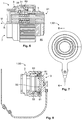
- Figs. 7 and 8 show a second embodiment of a connector assembly 1 according to the invention.
- Fig. 7 shows a front view of the connector assembly 1
- Fig. 8 shows a longitudinal cut of the connector assembly 1, which is indicated by the line A-A in Fig. 7 .
- the second embodiment of the connector assembly 1 is formed as a protective cover 93 for the complementary connector 11. For the sake of brevity, only the differences to the first embodiment are described.
- the connector body 5 is closed at its rear end 9.
- a gasket 95 is arranged in the connector body 5.
- the gasket 95 may press against the complementary connector 11 in a mated state. Thereby, the gasket 95 may close the cylindrically shaped complementary connector 11.
- the protective cover 93 comprises a latching arrangement 81 according to the invention. Further, the protective cover 93 preferably comprises a drive system 89 according to the first embodiment. In the case that the connector assembly 1 is formed as a protective cover 93, the mating and unmating may function according to the first embodiment of the connector assembly 1. During rotation of the fixation sleeve 3 with respect to the connector body 5, the drive system 89 moves the connector body 5 towards the complementary connector 11, such that the gasket 95 is pressed against the complementary connector 11.
- the connector body 5 of the second embodiment is also provided with at least one sealing element 55 which may be arranged between the connector body 5 and the complementary connector 11 in a mated state (not shown).
- the latching arrangement 81 of the second embodiment provides an audible response when one of the latching positions 77 or 85 is reached.
Landscapes
- Details Of Connecting Devices For Male And Female Coupling (AREA)
Claims (11)
- Verbinder-Baugruppe (1) für eine Verbindung mit einem komplementären Verbinder (11), die einen Verbinder-Körper (5) und eine Fixierhülse (3) umfasst, wobei die Fixierhülse (3) relativ zu dem Verbinder-Körper (5) drehbar an dem Verbinder-Körper (5) gehalten wird und der Verbinder-Körper (5) wenigstens teilweise im Inneren der Fixierhülse (3) angeordnet ist, wobei die Verbinder-Baugruppe (1) des Weiteren wenigstens ein Fixierelement für Eingriff mit dem komplementären Verbinder (11) umfasst, die Verbinder-Baugruppe (1) eine Arretieranordnung (81) umfasst, die wenigstens zwei Arretierpositionen ermöglicht, wobei sich die Fixierhülse (3) in einer ersten Arretierposition (77) der wenigstens zwei Arretierpositionen (77, 85) in einer anderen Winkelposition relativ zu dem Verbinder-Körper (5) befindet als in einer zweiten Arretierposition (85) der wenigstens zwei Arretierpositionen und die Fixierhülse (3) mit dem Verbinder-Körper (5) über wenigstens ein Antriebssystem (89) gekoppelt ist, das so eingerichtet ist, dass es eine Drehung der Fixierhülse (3) in eine axiale Bewegung des Verbinder-Körpers (5) umwandelt, dadurch gekennzeichnet, dass das wenigstens eine Antriebssystem (89) drei Nockenbahnen (39) sowie drei Stift-elemente (31) umfasst, wobei die Nockenbahnen (39) an einem Außenumfang des Verbin-der-Körpers (5) angeordnet sind und wenigstens teilweise spiralförmig um eine Dreh-achse (R) der Fixierhülse (3) herum verlaufen und die drei Stiftelemente (31) in einem zusammengebauten Zustand der Verbinder-Baugruppe (1) von einem Innenumfang (15) der Fixierhülse (3) in die Nockenbahnen (39) in dem Verbinder-Körper (5) hinein vorstehen.
- Verbinder-Baugruppe (1) nach Anspruch 1 dadurch gekennzeichnet, dass die wenigs-tens eine Arretieranordnung (81) wenigstens eine der folgenden Konstruktionen umfasst:wenigstens ein elastisch verformbares Arretierelement (25) an dem Verbinder-Körper (5) oder/und der Fixierhülse (3), sowie wenigstens zwei Aufnahmeaussparungen (23) für das wenigstens eine Arretierelement (25) in der Fixierhülse (3) oder/und dem Verbinder-Körper (5), oderwenigstens zwei elastisch verformbare Arretierelemente (25) an dem Verbinder-Körper (5) oder/und der Fixierhülse (3), sowie wenigstens eine Aufnahmeaussparung (23) für die wenigstens zwei Arretierelemente (25) in der Fixierhülse (3) oder/und dem Verbinder-Körper (5).
- Verbinder-Baugruppe (1) nach Anspruch 2, dadurch gekennzeichnet, dass das wenigstens eine elastisch verformbare Arretierelement (25) eine Druckfeder (43) und ein kugelförmiges Arretierelement (45) umfasst.
- Verbinder-Baugruppe (1) nach Anspruch 3, dadurch gekennzeichnet, dass die wenigstens eine Druckfeder (43) in einer Aussparung (41) in einem Außenumfang (37) des Verbinder-Körpers (5) oder in einem Innenumfang (15) der Fixierhülse (3) aufgenommen ist.
- Verbinder-Baugruppe (1) nach einem der Ansprüche 2 bis 4, dadurch gekennzeichnet, dass die wenigstens eine Aufnahmeaussparung (23) als eine Nut (21) ausgebildet ist, die parallel zu einer Drehachse (R) der Fixierhülse (3) verläuft.
- Verbinder-Baugruppe (1) nach einem der Ansprüche 1 bis 5, dadurch gekennzeichnet, dass der Verbinder-Körper (5) in der ersten und der zweiten Arretierposition (77, 85) an unterschiedlichen axialen Positionen (83, 91) relativ zu der Fixierhülse (3) angeordnet ist.
- Verbinder-Baugruppe (1) nach einem der Ansprüche 1 bis 6, dadurch gekennzeichnet, dass das Antriebssystem (89) teilweise in der Fixierhülse (3) und teilweise in dem Verbinder-Körper (5) angeordnet ist.
- Verbinder-Baugruppe (1) nach einem der Ansprüche 1 bis 7, dadurch gekennzeichnet, dass die Fixierhülse (3) mit wenigstens einer ersten Ausrichtstruktur (19) versehen ist und dass der Verbinder-Körper (5) mit wenigstens einer zweiten Ausrichtstruktur (49) versehen ist, wobei in der ersten Arretierposition (77) die erste und die zweite Struktur (19, 49) so ausgerichtet sind, dass wenigstens ein durchgehender Einführungsweg (79) für wenigstens eine komplementäre Ausrichtstruktur (61) des komplementären Verbinders (11) parallel zu der Drehachse (R) der Fixierhülse (3) verläuft.
- Verbinder-Baugruppe (1) nach Anspruch 8, dadurch gekennzeichnet, dass in der zweiten Arretierposition (85) die wenigstens eine erste Ausrichtstruktur (19) und die wenigstens eine zweite Struktur (49) so ausgerichtet sind, dass der wenigstens eine Einführungsweg (79) unterbrochen wird.
- Verbinder-Anordnung (59), die eine Baugruppe (1) nach einem der Ansprüche 1 bis 9 sowie einen komplementären Verbinder (11) mit wenigstens einem Gegen-Fixierelement (75) umfasst, das komplementär zu dem wenigstens einen Fixierelement (13) der Fixierhülse (3) der Verbinder-Baugruppe (1) ausgeführt ist, so dass, in einem verbundenen Zustand das wenigstens eine Fixierelement (13) und das wenigstens eine Gegen-Fixierelement (75) wenigstens entgegengesetzt zu einer Einpass-Richtung (M) der Verbinder-Baugruppe (1), die parallel zu einer Drehachse (R) der Fixierhülse (3) ist, formschlüssig aneinander arretiert werden.
- Verbinder-Anordnung (59) nach Anspruch 10, dadurch gekennzeichnet, dass der kom-plementäre Verbinder (11) mit wenigstens einer komplementären Ausrichtstruktur (61) versehen ist, die wenigstens teilweise komplementär zu der wenigstens einen ersten Aus-richtstruktur (19) und der wenigstens einen zweiten Ausrichtstruktur (49) der Verbinder-Anordnung (1) geformt ist, und dass die Verbinder-Anordnung (1) nur dann mit dem kom-plementären Verbinder (11) verbunden werden kann, wenn sich die Fixierhülse (3) in der ersten Arretierposition (77) befindet.
Priority Applications (2)
| Application Number | Priority Date | Filing Date | Title |
|---|---|---|---|
| EP16186399.8A EP3291380B1 (de) | 2016-08-30 | 2016-08-30 | Verbinderanordnung mit einer verriegelungsanordnung |
| US15/689,730 US10320118B2 (en) | 2016-08-30 | 2017-08-29 | Connector with a latching assembly |
Applications Claiming Priority (1)
| Application Number | Priority Date | Filing Date | Title |
|---|---|---|---|
| EP16186399.8A EP3291380B1 (de) | 2016-08-30 | 2016-08-30 | Verbinderanordnung mit einer verriegelungsanordnung |
Publications (2)
| Publication Number | Publication Date |
|---|---|
| EP3291380A1 EP3291380A1 (de) | 2018-03-07 |
| EP3291380B1 true EP3291380B1 (de) | 2021-09-22 |
Family
ID=56855286
Family Applications (1)
| Application Number | Title | Priority Date | Filing Date |
|---|---|---|---|
| EP16186399.8A Active EP3291380B1 (de) | 2016-08-30 | 2016-08-30 | Verbinderanordnung mit einer verriegelungsanordnung |
Country Status (2)
| Country | Link |
|---|---|
| US (1) | US10320118B2 (de) |
| EP (1) | EP3291380B1 (de) |
Families Citing this family (8)
| Publication number | Priority date | Publication date | Assignee | Title |
|---|---|---|---|---|
| EP3291380B1 (de) * | 2016-08-30 | 2021-09-22 | Polamco Limited | Verbinderanordnung mit einer verriegelungsanordnung |
| US20190123487A1 (en) * | 2017-10-23 | 2019-04-25 | Conesys, Inc. | Circular connectors |
| US11128076B2 (en) * | 2019-01-21 | 2021-09-21 | Cadwell Laboratories, Inc. | Connector receptacle |
| DE102019130628B4 (de) * | 2019-11-13 | 2021-08-05 | Hummel Ag | Steckverbinderkupplung |
| CN112603397B (zh) * | 2020-12-23 | 2022-04-12 | 北京市春立正达医疗器械股份有限公司 | 一种制动式关节软组织撑开器 |
| US12542408B2 (en) * | 2022-12-14 | 2026-02-03 | Te Connectivity Solutions Gmbh | Circular plug connector with anti-rotation mechanism |
| DE102023104462A1 (de) * | 2023-02-23 | 2024-08-29 | Te Connectivity Solutions Gmbh | Berührungsschutzabdeckung, Anschlussteil, Modulverbinder und Batteriesystem |
| US12597743B2 (en) | 2023-05-08 | 2026-04-07 | Rolls-Royce Corporation | Variable length wire harness for electronic devices |
Family Cites Families (26)
| Publication number | Priority date | Publication date | Assignee | Title |
|---|---|---|---|---|
| US2703870A (en) * | 1954-02-12 | 1955-03-08 | Robert W Minto | Electrical connector |
| US2987691A (en) * | 1958-10-20 | 1961-06-06 | Specialty Engineering & Electr | Quick-coupling hermaphroditic connectors |
| US3111355A (en) * | 1962-02-12 | 1963-11-19 | Serge N Samburoff | Missile electrical plug connector |
| US3287031A (en) * | 1964-09-21 | 1966-11-22 | William H Simmons | Indexed keyed connection |
| NL137273B (de) * | 1966-04-08 | |||
| US3440371A (en) * | 1967-03-10 | 1969-04-22 | Gen Electric | Jackscrew type racking mechanism for drawout switchgear |
| US3629791A (en) * | 1968-09-30 | 1971-12-21 | Bendix Corp | Electrical connector |
| US4629272A (en) * | 1985-04-04 | 1986-12-16 | Matrix Science Corporation | Electrical connector assembly with anti-rotation latch mechanism |
| FR2587144B1 (fr) * | 1985-09-06 | 1988-04-29 | Drogo Pierre | Connecteur electrique multibroche |
| GB2217927B (en) * | 1988-03-12 | 1992-04-01 | Electronic Components Ltd | Bayonet coupling connector |
| US4836794A (en) * | 1988-08-05 | 1989-06-06 | Kern Engineering & Mfg. Corp. | EMI and environmentally protected connector cap |
| US5010426A (en) * | 1989-02-03 | 1991-04-23 | Zenith Data Systems Corporation | Installation mechanism for removable computer drive module |
| GB8912650D0 (en) * | 1989-06-02 | 1989-07-19 | Barnes Austen B | Axial locking device |
| US5082454A (en) * | 1989-09-28 | 1992-01-21 | Joslyn Corporation | Two-piece retaining ring |
| US4984995A (en) * | 1989-11-13 | 1991-01-15 | Icore International, Inc. | Anti-decoupling device for electrical conduit connector |
| JPH03227158A (ja) * | 1990-02-01 | 1991-10-08 | Oki Electric Ind Co Ltd | 車載・携帯兼用電話機の車載収納装置 |
| JP2914088B2 (ja) * | 1993-04-16 | 1999-06-28 | 住友電装株式会社 | 回転ガイド付きコネクタ |
| US6716048B2 (en) * | 2001-03-14 | 2004-04-06 | Itt Manufacturing Enterprises, Inc. | Coupling mechanism for electrical connectors |
| CN100428607C (zh) * | 2005-10-18 | 2008-10-22 | 台达电子工业股份有限公司 | 具切换式连接机构的不断电供电系统 |
| GB0526237D0 (en) * | 2005-12-23 | 2006-02-01 | Rota Eng Ltd | Connector |
| US8405253B2 (en) * | 2009-12-21 | 2013-03-26 | Whirlpool Corporation | Mechanically energized eService connector system |
| US8246372B1 (en) * | 2010-05-27 | 2012-08-21 | Williams-Pyro, Inc. | Electrical connector with anchor mount |
| CN102610957B (zh) * | 2011-01-20 | 2014-09-10 | 鸿富锦精密工业(深圳)有限公司 | 连接器 |
| FR2997800B1 (fr) * | 2012-11-06 | 2015-01-30 | Souriau | Systeme de verrouillage securise et connecteur comportant un tel systeme |
| JP6210829B2 (ja) * | 2013-10-04 | 2017-10-11 | 矢崎総業株式会社 | コネクタ |
| EP3291380B1 (de) * | 2016-08-30 | 2021-09-22 | Polamco Limited | Verbinderanordnung mit einer verriegelungsanordnung |
-
2016
- 2016-08-30 EP EP16186399.8A patent/EP3291380B1/de active Active
-
2017
- 2017-08-29 US US15/689,730 patent/US10320118B2/en active Active
Also Published As
| Publication number | Publication date |
|---|---|
| US20180062308A1 (en) | 2018-03-01 |
| US10320118B2 (en) | 2019-06-11 |
| EP3291380A1 (de) | 2018-03-07 |
Similar Documents
| Publication | Publication Date | Title |
|---|---|---|
| EP3291380B1 (de) | Verbinderanordnung mit einer verriegelungsanordnung | |
| US10465827B2 (en) | Plug-in connector for fluid lines with inner adapter sleeve | |
| EP3218965B1 (de) | Verbinderbaugruppe | |
| US9312629B2 (en) | Plug connector | |
| EP2975700B1 (de) | Gehäuseanordnung | |
| US7862366B2 (en) | Electrical connector with locking clip | |
| EP2960695B1 (de) | Verbinder für ein Kabel und Verbinderanordnung | |
| EP1630905B1 (de) | Mehrphasenverbinder | |
| CN103782456A (zh) | 保护触点的插塞连接器 | |
| KR20020087471A (ko) | 회전식 퀵 커넥터 | |
| CN102074838A (zh) | 具有锁圈的电连接器 | |
| JP6875599B2 (ja) | 係止要素を備えた電気コネクタ部品 | |
| CN101390261A (zh) | 电的插塞装置 | |
| US20170162981A1 (en) | Connector and Connector Assembly | |
| US12237628B2 (en) | Ganged coaxial connector assembly with removable connector-cable configuration | |
| US11378119B2 (en) | Anti-vibration locking connector | |
| JP2019129148A (ja) | コネクタ | |
| US11276951B2 (en) | Socket-outlet equipped with a disc and a shutter | |
| US8079868B2 (en) | Electrical connector with releasable locking clip | |
| EP2715876B1 (de) | Gehäuse für einen elektrischen verbinder und vorrichtung für ein fahrzeugaufladesystem | |
| EP3525295B1 (de) | Abgedichteter verbinder mit axialer montage |
Legal Events
| Date | Code | Title | Description |
|---|---|---|---|
| PUAI | Public reference made under article 153(3) epc to a published international application that has entered the european phase |
Free format text: ORIGINAL CODE: 0009012 |
|
| STAA | Information on the status of an ep patent application or granted ep patent |
Free format text: STATUS: THE APPLICATION HAS BEEN PUBLISHED |
|
| AK | Designated contracting states |
Kind code of ref document: A1 Designated state(s): AL AT BE BG CH CY CZ DE DK EE ES FI FR GB GR HR HU IE IS IT LI LT LU LV MC MK MT NL NO PL PT RO RS SE SI SK SM TR |
|
| AX | Request for extension of the european patent |
Extension state: BA ME |
|
| STAA | Information on the status of an ep patent application or granted ep patent |
Free format text: STATUS: REQUEST FOR EXAMINATION WAS MADE |
|
| 17P | Request for examination filed |
Effective date: 20180906 |
|
| RBV | Designated contracting states (corrected) |
Designated state(s): AL AT BE BG CH CY CZ DE DK EE ES FI FR GB GR HR HU IE IS IT LI LT LU LV MC MK MT NL NO PL PT RO RS SE SI SK SM TR |
|
| STAA | Information on the status of an ep patent application or granted ep patent |
Free format text: STATUS: EXAMINATION IS IN PROGRESS |
|
| 17Q | First examination report despatched |
Effective date: 20200213 |
|
| GRAP | Despatch of communication of intention to grant a patent |
Free format text: ORIGINAL CODE: EPIDOSNIGR1 |
|
| STAA | Information on the status of an ep patent application or granted ep patent |
Free format text: STATUS: GRANT OF PATENT IS INTENDED |
|
| RIC1 | Information provided on ipc code assigned before grant |
Ipc: H01R 13/627 20060101ALI20210219BHEP Ipc: H01R 13/64 20060101ALN20210219BHEP Ipc: H01R 13/625 20060101AFI20210219BHEP |
|
| RIC1 | Information provided on ipc code assigned before grant |
Ipc: H01R 13/625 20060101AFI20210301BHEP Ipc: H01R 13/627 20060101ALI20210301BHEP Ipc: H01R 13/64 20060101ALN20210301BHEP |
|
| INTG | Intention to grant announced |
Effective date: 20210316 |
|
| GRAS | Grant fee paid |
Free format text: ORIGINAL CODE: EPIDOSNIGR3 |
|
| GRAA | (expected) grant |
Free format text: ORIGINAL CODE: 0009210 |
|
| STAA | Information on the status of an ep patent application or granted ep patent |
Free format text: STATUS: THE PATENT HAS BEEN GRANTED |
|
| AK | Designated contracting states |
Kind code of ref document: B1 Designated state(s): AL AT BE BG CH CY CZ DE DK EE ES FI FR GB GR HR HU IE IS IT LI LT LU LV MC MK MT NL NO PL PT RO RS SE SI SK SM TR |
|
| REG | Reference to a national code |
Ref country code: GB Ref legal event code: FG4D |
|
| REG | Reference to a national code |
Ref country code: IE Ref legal event code: FG4D |
|
| REG | Reference to a national code |
Ref country code: DE Ref legal event code: R096 Ref document number: 602016063944 Country of ref document: DE |
|
| REG | Reference to a national code |
Ref country code: CH Ref legal event code: EP Ref country code: AT Ref legal event code: REF Ref document number: 1433035 Country of ref document: AT Kind code of ref document: T Effective date: 20211015 |
|
| REG | Reference to a national code |
Ref country code: DE Ref legal event code: R081 Ref document number: 602016063944 Country of ref document: DE Owner name: TYCO ELECTRONICS UK LTD., SWINDON, GB Free format text: FORMER OWNER: POLAMCO LTD., BATH, GB |
|
| RAP2 | Party data changed (patent owner data changed or rights of a patent transferred) |
Owner name: TYCO ELECTRONICS UK LTD. |
|
| REG | Reference to a national code |
Ref country code: GB Ref legal event code: 732E Free format text: REGISTERED BETWEEN 20211111 AND 20211117 |
|
| REG | Reference to a national code |
Ref country code: LT Ref legal event code: MG9D |
|
| REG | Reference to a national code |
Ref country code: NL Ref legal event code: MP Effective date: 20210922 |
|
| PG25 | Lapsed in a contracting state [announced via postgrant information from national office to epo] |
Ref country code: SE Free format text: LAPSE BECAUSE OF FAILURE TO SUBMIT A TRANSLATION OF THE DESCRIPTION OR TO PAY THE FEE WITHIN THE PRESCRIBED TIME-LIMIT Effective date: 20210922 Ref country code: RS Free format text: LAPSE BECAUSE OF FAILURE TO SUBMIT A TRANSLATION OF THE DESCRIPTION OR TO PAY THE FEE WITHIN THE PRESCRIBED TIME-LIMIT Effective date: 20210922 Ref country code: HR Free format text: LAPSE BECAUSE OF FAILURE TO SUBMIT A TRANSLATION OF THE DESCRIPTION OR TO PAY THE FEE WITHIN THE PRESCRIBED TIME-LIMIT Effective date: 20210922 Ref country code: NO Free format text: LAPSE BECAUSE OF FAILURE TO SUBMIT A TRANSLATION OF THE DESCRIPTION OR TO PAY THE FEE WITHIN THE PRESCRIBED TIME-LIMIT Effective date: 20211222 Ref country code: FI Free format text: LAPSE BECAUSE OF FAILURE TO SUBMIT A TRANSLATION OF THE DESCRIPTION OR TO PAY THE FEE WITHIN THE PRESCRIBED TIME-LIMIT Effective date: 20210922 Ref country code: LT Free format text: LAPSE BECAUSE OF FAILURE TO SUBMIT A TRANSLATION OF THE DESCRIPTION OR TO PAY THE FEE WITHIN THE PRESCRIBED TIME-LIMIT Effective date: 20210922 Ref country code: BG Free format text: LAPSE BECAUSE OF FAILURE TO SUBMIT A TRANSLATION OF THE DESCRIPTION OR TO PAY THE FEE WITHIN THE PRESCRIBED TIME-LIMIT Effective date: 20211222 |
|
| REG | Reference to a national code |
Ref country code: AT Ref legal event code: MK05 Ref document number: 1433035 Country of ref document: AT Kind code of ref document: T Effective date: 20210922 |
|
| PG25 | Lapsed in a contracting state [announced via postgrant information from national office to epo] |
Ref country code: LV Free format text: LAPSE BECAUSE OF FAILURE TO SUBMIT A TRANSLATION OF THE DESCRIPTION OR TO PAY THE FEE WITHIN THE PRESCRIBED TIME-LIMIT Effective date: 20210922 Ref country code: GR Free format text: LAPSE BECAUSE OF FAILURE TO SUBMIT A TRANSLATION OF THE DESCRIPTION OR TO PAY THE FEE WITHIN THE PRESCRIBED TIME-LIMIT Effective date: 20211223 |
|
| PG25 | Lapsed in a contracting state [announced via postgrant information from national office to epo] |
Ref country code: AT Free format text: LAPSE BECAUSE OF FAILURE TO SUBMIT A TRANSLATION OF THE DESCRIPTION OR TO PAY THE FEE WITHIN THE PRESCRIBED TIME-LIMIT Effective date: 20210922 |
|
| PG25 | Lapsed in a contracting state [announced via postgrant information from national office to epo] |
Ref country code: IS Free format text: LAPSE BECAUSE OF FAILURE TO SUBMIT A TRANSLATION OF THE DESCRIPTION OR TO PAY THE FEE WITHIN THE PRESCRIBED TIME-LIMIT Effective date: 20220122 Ref country code: SK Free format text: LAPSE BECAUSE OF FAILURE TO SUBMIT A TRANSLATION OF THE DESCRIPTION OR TO PAY THE FEE WITHIN THE PRESCRIBED TIME-LIMIT Effective date: 20210922 Ref country code: RO Free format text: LAPSE BECAUSE OF FAILURE TO SUBMIT A TRANSLATION OF THE DESCRIPTION OR TO PAY THE FEE WITHIN THE PRESCRIBED TIME-LIMIT Effective date: 20210922 Ref country code: PT Free format text: LAPSE BECAUSE OF FAILURE TO SUBMIT A TRANSLATION OF THE DESCRIPTION OR TO PAY THE FEE WITHIN THE PRESCRIBED TIME-LIMIT Effective date: 20220124 Ref country code: PL Free format text: LAPSE BECAUSE OF FAILURE TO SUBMIT A TRANSLATION OF THE DESCRIPTION OR TO PAY THE FEE WITHIN THE PRESCRIBED TIME-LIMIT Effective date: 20210922 Ref country code: NL Free format text: LAPSE BECAUSE OF FAILURE TO SUBMIT A TRANSLATION OF THE DESCRIPTION OR TO PAY THE FEE WITHIN THE PRESCRIBED TIME-LIMIT Effective date: 20210922 Ref country code: ES Free format text: LAPSE BECAUSE OF FAILURE TO SUBMIT A TRANSLATION OF THE DESCRIPTION OR TO PAY THE FEE WITHIN THE PRESCRIBED TIME-LIMIT Effective date: 20210922 Ref country code: EE Free format text: LAPSE BECAUSE OF FAILURE TO SUBMIT A TRANSLATION OF THE DESCRIPTION OR TO PAY THE FEE WITHIN THE PRESCRIBED TIME-LIMIT Effective date: 20210922 Ref country code: CZ Free format text: LAPSE BECAUSE OF FAILURE TO SUBMIT A TRANSLATION OF THE DESCRIPTION OR TO PAY THE FEE WITHIN THE PRESCRIBED TIME-LIMIT Effective date: 20210922 Ref country code: AL Free format text: LAPSE BECAUSE OF FAILURE TO SUBMIT A TRANSLATION OF THE DESCRIPTION OR TO PAY THE FEE WITHIN THE PRESCRIBED TIME-LIMIT Effective date: 20210922 |
|
| REG | Reference to a national code |
Ref country code: DE Ref legal event code: R097 Ref document number: 602016063944 Country of ref document: DE |
|
| PG25 | Lapsed in a contracting state [announced via postgrant information from national office to epo] |
Ref country code: DK Free format text: LAPSE BECAUSE OF FAILURE TO SUBMIT A TRANSLATION OF THE DESCRIPTION OR TO PAY THE FEE WITHIN THE PRESCRIBED TIME-LIMIT Effective date: 20210922 |
|
| PLBE | No opposition filed within time limit |
Free format text: ORIGINAL CODE: 0009261 |
|
| STAA | Information on the status of an ep patent application or granted ep patent |
Free format text: STATUS: NO OPPOSITION FILED WITHIN TIME LIMIT |
|
| 26N | No opposition filed |
Effective date: 20220623 |
|
| PG25 | Lapsed in a contracting state [announced via postgrant information from national office to epo] |
Ref country code: SI Free format text: LAPSE BECAUSE OF FAILURE TO SUBMIT A TRANSLATION OF THE DESCRIPTION OR TO PAY THE FEE WITHIN THE PRESCRIBED TIME-LIMIT Effective date: 20210922 |
|
| PG25 | Lapsed in a contracting state [announced via postgrant information from national office to epo] |
Ref country code: IT Free format text: LAPSE BECAUSE OF FAILURE TO SUBMIT A TRANSLATION OF THE DESCRIPTION OR TO PAY THE FEE WITHIN THE PRESCRIBED TIME-LIMIT Effective date: 20210922 |
|
| PG25 | Lapsed in a contracting state [announced via postgrant information from national office to epo] |
Ref country code: MC Free format text: LAPSE BECAUSE OF FAILURE TO SUBMIT A TRANSLATION OF THE DESCRIPTION OR TO PAY THE FEE WITHIN THE PRESCRIBED TIME-LIMIT Effective date: 20210922 |
|
| REG | Reference to a national code |
Ref country code: CH Ref legal event code: PL |
|
| PG25 | Lapsed in a contracting state [announced via postgrant information from national office to epo] |
Ref country code: LU Free format text: LAPSE BECAUSE OF NON-PAYMENT OF DUE FEES Effective date: 20220830 Ref country code: LI Free format text: LAPSE BECAUSE OF NON-PAYMENT OF DUE FEES Effective date: 20220831 Ref country code: CH Free format text: LAPSE BECAUSE OF NON-PAYMENT OF DUE FEES Effective date: 20220831 |
|
| REG | Reference to a national code |
Ref country code: BE Ref legal event code: MM Effective date: 20220831 |
|
| PG25 | Lapsed in a contracting state [announced via postgrant information from national office to epo] |
Ref country code: IE Free format text: LAPSE BECAUSE OF NON-PAYMENT OF DUE FEES Effective date: 20220830 |
|
| PG25 | Lapsed in a contracting state [announced via postgrant information from national office to epo] |
Ref country code: BE Free format text: LAPSE BECAUSE OF NON-PAYMENT OF DUE FEES Effective date: 20220831 |
|
| PG25 | Lapsed in a contracting state [announced via postgrant information from national office to epo] |
Ref country code: HU Free format text: LAPSE BECAUSE OF FAILURE TO SUBMIT A TRANSLATION OF THE DESCRIPTION OR TO PAY THE FEE WITHIN THE PRESCRIBED TIME-LIMIT; INVALID AB INITIO Effective date: 20160830 |
|
| PG25 | Lapsed in a contracting state [announced via postgrant information from national office to epo] |
Ref country code: SM Free format text: LAPSE BECAUSE OF FAILURE TO SUBMIT A TRANSLATION OF THE DESCRIPTION OR TO PAY THE FEE WITHIN THE PRESCRIBED TIME-LIMIT Effective date: 20210922 Ref country code: CY Free format text: LAPSE BECAUSE OF FAILURE TO SUBMIT A TRANSLATION OF THE DESCRIPTION OR TO PAY THE FEE WITHIN THE PRESCRIBED TIME-LIMIT Effective date: 20210922 |
|
| PG25 | Lapsed in a contracting state [announced via postgrant information from national office to epo] |
Ref country code: MK Free format text: LAPSE BECAUSE OF FAILURE TO SUBMIT A TRANSLATION OF THE DESCRIPTION OR TO PAY THE FEE WITHIN THE PRESCRIBED TIME-LIMIT Effective date: 20210922 |
|
| PG25 | Lapsed in a contracting state [announced via postgrant information from national office to epo] |
Ref country code: MT Free format text: LAPSE BECAUSE OF FAILURE TO SUBMIT A TRANSLATION OF THE DESCRIPTION OR TO PAY THE FEE WITHIN THE PRESCRIBED TIME-LIMIT Effective date: 20210922 |
|
| PGFP | Annual fee paid to national office [announced via postgrant information from national office to epo] |
Ref country code: DE Payment date: 20250702 Year of fee payment: 10 |
|
| PGFP | Annual fee paid to national office [announced via postgrant information from national office to epo] |
Ref country code: GB Payment date: 20250703 Year of fee payment: 10 |
|
| PGFP | Annual fee paid to national office [announced via postgrant information from national office to epo] |
Ref country code: FR Payment date: 20250703 Year of fee payment: 10 |
|
| PG25 | Lapsed in a contracting state [announced via postgrant information from national office to epo] |
Ref country code: TR Free format text: LAPSE BECAUSE OF FAILURE TO SUBMIT A TRANSLATION OF THE DESCRIPTION OR TO PAY THE FEE WITHIN THE PRESCRIBED TIME-LIMIT Effective date: 20210922 |