EP3291404A1 - Procédé et dispositif de mise en oeuvre d'une commande de connexion - Google Patents
Procédé et dispositif de mise en oeuvre d'une commande de connexion Download PDFInfo
- Publication number
- EP3291404A1 EP3291404A1 EP15890460.7A EP15890460A EP3291404A1 EP 3291404 A1 EP3291404 A1 EP 3291404A1 EP 15890460 A EP15890460 A EP 15890460A EP 3291404 A1 EP3291404 A1 EP 3291404A1
- Authority
- EP
- European Patent Office
- Prior art keywords
- data line
- state
- electric equipment
- connection
- wireless charging
- Prior art date
- Legal status (The legal status is an assumption and is not a legal conclusion. Google has not performed a legal analysis and makes no representation as to the accuracy of the status listed.)
- Withdrawn
Links
Images

Classifications
-
- H—ELECTRICITY
- H02—GENERATION; CONVERSION OR DISTRIBUTION OF ELECTRIC POWER
- H02J—ELECTRIC POWER NETWORKS; CIRCUIT ARRANGEMENTS OR SYSTEMS FOR SUPPLYING OR DISTRIBUTING ELECTRIC POWER; SYSTEMS FOR STORING ELECTRIC ENERGY
- H02J7/00—Circuit arrangements for charging or discharging batteries or for supplying loads from batteries
-
- G—PHYSICS
- G05—CONTROLLING; REGULATING
- G05B—CONTROL OR REGULATING SYSTEMS IN GENERAL; FUNCTIONAL ELEMENTS OF SUCH SYSTEMS; MONITORING OR TESTING ARRANGEMENTS FOR SUCH SYSTEMS OR ELEMENTS
- G05B19/00—Program-control systems
- G05B19/02—Program-control systems electric
- G05B19/04—Program control other than numerical control, i.e. in sequence controllers or logic controllers
- G05B19/10—Program control other than numerical control, i.e. in sequence controllers or logic controllers using selector switches
-
- G—PHYSICS
- G05—CONTROLLING; REGULATING
- G05B—CONTROL OR REGULATING SYSTEMS IN GENERAL; FUNCTIONAL ELEMENTS OF SUCH SYSTEMS; MONITORING OR TESTING ARRANGEMENTS FOR SUCH SYSTEMS OR ELEMENTS
- G05B2219/00—Program-control systems
- G05B2219/20—Pc systems
- G05B2219/26—Pc applications
- G05B2219/2639—Energy management, use maximum of cheap power, keep peak load low
-
- H—ELECTRICITY
- H02—GENERATION; CONVERSION OR DISTRIBUTION OF ELECTRIC POWER
- H02J—ELECTRIC POWER NETWORKS; CIRCUIT ARRANGEMENTS OR SYSTEMS FOR SUPPLYING OR DISTRIBUTING ELECTRIC POWER; SYSTEMS FOR STORING ELECTRIC ENERGY
- H02J7/00—Circuit arrangements for charging or discharging batteries or for supplying loads from batteries
- H02J7/40—Circuit arrangements for charging or discharging batteries or for supplying loads from batteries characterised by the exchange of charge or discharge related data
- H02J7/42—Circuit arrangements for charging or discharging batteries or for supplying loads from batteries characterised by the exchange of charge or discharge related data with electronic devices having internal batteries, e.g. mobile phones
Definitions
- the present disclosure relates to electronic control technologies, and more particularly, to a method and device for implementing connection control.
- wireless charging stems from the wireless power transmission technologies, in which energy is transmitted by power supply equipment (chargers) to electric devices by means of inductive coupling to charge batteries. Energy transmission between the power supply equipment and the electric devices can be implemented through inductive coupling. Therefore, the power supply equipment and the electric devices may implement nonconductive contact point exposure without wired connection.
- power supply equipment chargers
- inductive coupling energy transmission between the power supply equipment and the electric devices can be implemented through inductive coupling. Therefore, the power supply equipment and the electric devices may implement nonconductive contact point exposure without wired connection.
- receivers of the electric devices are charged by converting AC signal to 5V DC signal.
- the output signal is only a power line and a ground wire.
- Charging managers of most of electric devices in the market regard by default, chargers only provided with power lines and ground wires as a computer connection entry USB mode. In this mode, charging current less than or equal to 500mA (such as 450mA) can be supplied.
- Counting system consumption in, current actually available for battery charging is only about 400mA, which leads to a slow charging process. Therefore, the above mode is slow in charging and unable to meet charging demands of users, which affects the application of the wireless charging technologies.
- the wireless charging is configured as AC charging since the charge manager has completed the enumeration of charge types.
- the wireless charging is interrupted, after the USB connection is disconnected or the OTG equipment is removed, it is impossible to recover the wireless charging because the wireless charging communication is disconnected. That is, because of cutoff of wireless charging, the charging manager performs enumeration of charge types. Therefore, it is still impossible to recognize disconnection of the USB connection or removal of the OTG equipment.
- the method of using two charging managers has a great impact on the electric devices in cost and PCB layout, which is to the disadvantage of application of the electric devices.
- the method of using one charging manager is adopted, it is impossible to recognize connection of a computer or OTG equipment after completing enumeration of wireless charging, and it is impossible to recognize disconnection of the USB connection or removal of the OTG equipment after completing enumeration of connection of the computer or OTG equipment. Therefore, the method of using one charging manager is also unavailable for wireless charging.
- Embodiments of the present disclosure provide a method and device for implementing connection control, which can recognize a connection state of an electric terminal, thereby correctly performing corresponding connection control.
- An embodiment of the present disclosure provides a method for implementing connection control, including:
- connection parameter information includes one or more of following parameters:
- the determining, according to the connection parameter information, a connection state of electric equipment includes:
- the controlling, according to the connection state of the electric equipment, ON or OFF of a circuit and/or an enabled state of the circuit includes:
- ON or OFF of the circuit is implemented by means of one or more analog switches.
- An embodiment of the present disclosure also provides a device for implementing connection control, which includes a determining unit and a switching unit.
- the determining unit is configured to read connection parameter information from a charging manager, and determine, according to the connection parameter information, a connection state of electric equipment.
- the switching unit is configured to control, according to the connection state of the electric equipment, ON or OFF of a circuit and/or an enabled state of the circuit.
- connection parameter information includes one or more of following parameters: a wireless charging state parameter CHG, a power line VBUS ON state, an external power input pin voltage value, and an ID detection parameter for determining whether there is an On-The-Go (OTG) equipment connection.
- a wireless charging state parameter CHG a wireless charging state parameter
- a power line VBUS ON state a power line VBUS ON state
- an external power input pin voltage value a wireless charging state parameter CHG
- ID detection parameter for determining whether there is an On-The-Go (OTG) equipment connection.
- the determining, by the determining unit according to the connection parameter information, a connection state of electric equipment includes:
- the switching unit is configured to:
- the switching unit is configured to implement OFF or ON of the circuit by means of one or more analog switches according to the connection state of the electric equipment, and/or implement the enabled state of the circuit by means of an enable signal so as to implement switching control of connection.
- the device further includes a baseband chip unit, configured to control the analog switches and/or transmit a wireless charging enable or disenable signal according to a signal of the switching unit.
- a baseband chip unit configured to control the analog switches and/or transmit a wireless charging enable or disenable signal according to a signal of the switching unit.
- An embodiment of the present disclosure further provides a computer readable storage medium, which stores program instructions. When the program instructions are executed, the above method may be implemented.
- the technical solution of the embodiment of the present disclosure includes: reading connection parameter information from a charging manager, and determining, according to the connection parameter information, a connection state of electric equipment; and controlling, according to the connection state of the electric equipment, ON or OFF of a circuit and/or an enabled state of the circuit.
- the connection state of the electric equipment is determined according to the connection parameter information, thereby implementing the connection control. In this way, connection management of the electric equipment merely applicable to one charging manager is implemented, thereby reducing cost and guaranteeing the switching control of wireless charging or connection of the electric equipment when the connection changes.
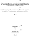
- FIG. 1 is a flowchart illustrating a method for implementing connection control according to an embodiment of the present disclosure. As shown in FIG. 1 , the method includes following steps.
- connection parameter information is read from a charging manager, and a connection state of electric equipment is determined according to the connection parameter information.
- connection parameter information includes one or more of following parameters:
- the determining, according to the connection parameter information, a connection state of electric equipment includes:
- Step 101 the switching control of connection is implemented by controlling, according to the connection state of the electric equipment, ON or OFF of a circuit and/or an enabled state of the circuit.
- a data line anode is disconnected from a data line cathode of the electric equipment, and connection between the data line anode and the data line cathode is turned on; or when the electric equipment is in the wired charging state, the connection of the data line anode and the data line cathode of the electric equipment is turned on, the data line anode is disconnected from the data line cathode, and a circuit controlling external power input is turned on; or when the electric equipment is in the USB-connecting computer state, the connection of the data line anode and the data line cathode of the electric equipment is turned on, the data line anode is disconnected from the data line cathode, and the circuit controlling external power input is turned on; or when the electric equipment is in the connection OTG equipment state, the connection of the data line anode and the data line cathode of the electric equipment is turned on, the data line anode is disconnected from the data line cathode, and the circuit controlling external power input is turned on; or when the electric equipment is in the
- ON or OFF of the circuit may be implemented by means of one or more analog switches.
- FIG. 2 is a block diagram illustrating a device for implementing connection control according to an embodiment of the present disclosure. As shown in FIG. 2 , the device includes a determining unit 200 and a switching unit 201.
- the determining unit 200 is configured to read connection parameter information from a charging manager, and determine, according to the connection parameter information, a connection state of electric equipment.
- the switching unit 201 is configured to control, according to the connection state of the electric equipment, ON or OFF of a circuit and/or an enabled state of the circuit.
- connection parameter information includes one or more of following parameters: a wireless charging state parameter CHG, a power line VBUS ON state, an external power input pin voltage value, and an ID detection parameter for determining whether there is an On-The-Go (OTG) equipment connection.
- a wireless charging state parameter CHG a wireless charging state parameter
- a power line VBUS ON state a power line VBUS ON state
- an external power input pin voltage value a wireless charging state parameter CHG
- ID detection parameter for determining whether there is an On-The-Go (OTG) equipment connection.
- the determining, by the determining unit 200 according to the connection parameter information, a connection state of electric equipment includes:
- the switching unit 201 is configured to:
- the switching unit 201 is configured to implement OFF or ON of the circuit by means of one or more analog switches according to the connection state of the electric equipment, and/or implement the enabled state of the circuit by means of an enable signal so as to implement switching control of connection.
- the device according to the embodiment of the present disclosure further includes a baseband chip unit, which is configured to control the analog switches and/or transmit a wireless charging enable or disenable signal according to a signal of the switching unit.
- FIG. 3 is a circuit connection diagram of electric equipment according to an application example.
- S1, S2, S3 and S4 represent analog switches, which are arranged in the circuit in the form of analog switch chips.
- a wireless charging output is connected to the analog switch S4.
- the S2 is configured to control ON or OFF of the data line anode of the electric equipment.
- the S1 is configured to control ON or OFF of the data line cathode of the electric equipment.
- the S3 is configured to control ON or OFF of a circuit between the data line anode and the data line cathode.
- the S4 is configured to control ON or OFF of a circuit of an external power input. Switches of the S1, S2, S3 and S4 are controlled by baseband signal.
- the wireless charging enable is controlled by an enable signal transmitted by the baseband chip.
- the connection parameter information read from a USB connector includes: a wireless charging state parameter CHG, a power line VBUS ON state, an external power input pin voltage value, and an ID detection parameter for determining whether there is an On-The-Go (OTG) equipment connection.
- the electric equipment is determined as a wireless charging state when the wireless charging state parameter CHG is a high level.
- the electric equipment is determined as a wired charging state when the power line VBUS ON state is ON and the external power input pin voltage value is greater than 3.6V.
- the electric equipment is determined as a USB-connecting computer state when the power line VBUS ON state is ON and the external power input pin voltage value is smaller than 3.6V.
- the electric equipment is determined as a connection OTG equipment state when the ID detection parameter determines there is OTG equipment.
- the electric equipment is determined as a USB-connecting computer and wireless charging disenabled state when the wireless charging state parameter CHG is a high level, the power line VBUS is ON and the external power input pin voltage value is smaller than 3.6V.
- the electric equipment is determined as a connection OTG equipment and wireless charging disenabled state when the wireless charging state parameter CHG is a high level and the ID detection parameter determines there is OTG equipment.
- the electric equipment is determined as an idle state when the wireless charging state parameter CHG is a low level, the power line VBUS is OFF and the ID detection parameter determines no OTG equipment is connected.
- the S1 and the S2 are turned off, the S3 is turned on, and the S4 is turned off.
- the S 1 and the S2 are turned on, the S3 is turned off, and the S4 is turned on.
- the S 1 and the S2 are turned on, the S3 is turned off, and the S4 is turned on.
- the S1 and the S2 are turned on, the S3 is turned off, a wireless charging disenabled signal is transmitted so that the wireless charging is disenabled, and the S4 is turned on.
- the S1 and the S2 are turned on, the S3 is turned off, the S4 is turned on, and a wireless charging disenabled signal is transmitted so that the wireless charging is disenabled.
- connection state of electric equipment is determined according to the connection parameter information, thereby implementing the connection control.
- connection management of the electric equipment merely applicable to one charging manager is implemented, thereby reducing cost and guaranteeing the switching control of wireless charging or connection of the electric equipment when the connection changes.
Landscapes
- Engineering & Computer Science (AREA)
- Power Engineering (AREA)
- Physics & Mathematics (AREA)
- General Physics & Mathematics (AREA)
- Automation & Control Theory (AREA)
- Charge And Discharge Circuits For Batteries Or The Like (AREA)
Applications Claiming Priority (2)
| Application Number | Priority Date | Filing Date | Title |
|---|---|---|---|
| CN201510216881.5A CN106200442B (zh) | 2015-04-30 | 2015-04-30 | 一种实现连接控制的方法及装置 |
| PCT/CN2015/080503 WO2016173081A1 (fr) | 2015-04-30 | 2015-06-01 | Procédé et dispositif de mise en œuvre d'une commande de connexion |
Publications (2)
| Publication Number | Publication Date |
|---|---|
| EP3291404A1 true EP3291404A1 (fr) | 2018-03-07 |
| EP3291404A4 EP3291404A4 (fr) | 2018-05-02 |
Family
ID=57198996
Family Applications (1)
| Application Number | Title | Priority Date | Filing Date |
|---|---|---|---|
| EP15890460.7A Withdrawn EP3291404A4 (fr) | 2015-04-30 | 2015-06-01 | Procédé et dispositif de mise en oeuvre d'une commande de connexion |
Country Status (4)
| Country | Link |
|---|---|
| US (1) | US10481576B2 (fr) |
| EP (1) | EP3291404A4 (fr) |
| CN (1) | CN106200442B (fr) |
| WO (1) | WO2016173081A1 (fr) |
Cited By (1)
| Publication number | Priority date | Publication date | Assignee | Title |
|---|---|---|---|---|
| US11011945B2 (en) | 2018-12-21 | 2021-05-18 | Western Digital Technologies, Inc. | Systems and methods for wireless charging and wired data transfer |
Families Citing this family (3)
| Publication number | Priority date | Publication date | Assignee | Title |
|---|---|---|---|---|
| CN108711719B (zh) * | 2018-03-30 | 2020-08-25 | 联想(北京)有限公司 | 一种接头及电子设备 |
| CN109687235B (zh) * | 2019-01-02 | 2021-03-16 | Oppo广东移动通信有限公司 | 一种控制电路和触点吸合式usb数据线 |
| NL2038642B1 (en) * | 2024-09-17 | 2026-04-02 | Liion Power B V | A USB charge management device arranged to control charging power levels |
Family Cites Families (12)
| Publication number | Priority date | Publication date | Assignee | Title |
|---|---|---|---|---|
| EP2092407B1 (fr) * | 2006-12-08 | 2013-01-23 | Nokia Corporation | Connexions multiples sur une interface série unique |
| JP5340803B2 (ja) * | 2009-05-18 | 2013-11-13 | 株式会社ソニー・コンピュータエンタテインメント | 情報処理装置 |
| KR101072276B1 (ko) * | 2009-10-21 | 2011-10-11 | 유노시스템 주식회사 | 무접점 충전, 데이터 통신시스템 |
| CN102222942A (zh) * | 2010-04-16 | 2011-10-19 | 联芯科技有限公司 | 电子设备的供电电路及充电方法 |
| KR101727495B1 (ko) * | 2010-12-28 | 2017-05-02 | 엘지전자 주식회사 | 이동 단말기 |
| CN103425220B (zh) * | 2012-05-22 | 2017-09-29 | 华为终端有限公司 | 一种电能控制模块、装置及设备 |
| KR101920236B1 (ko) * | 2012-06-19 | 2018-11-20 | 삼성전자주식회사 | 배터리를 충전하기 위한 방법 및 그 전자 장치 |
| CN202632567U (zh) * | 2012-06-21 | 2012-12-26 | 上海学创数码科技有限公司 | 无线充电式学习机 |
| US9461499B2 (en) * | 2012-09-07 | 2016-10-04 | Everpurse, Inc. | Personal wireless charging system |
| CN203387203U (zh) * | 2013-05-09 | 2014-01-08 | 上海斐讯数据通信技术有限公司 | 一种具有usb otg功能的充电切换系统 |
| CN104124732A (zh) * | 2014-06-27 | 2014-10-29 | 青岛众海汇智能源科技有限责任公司 | 基于usb接口的移动终端通用无线供电电路及其供电方法 |
| CN204167970U (zh) | 2014-11-14 | 2015-02-18 | 无锡中星微电子有限公司 | 充电管理电路及充电器 |
-
2015
- 2015-04-30 CN CN201510216881.5A patent/CN106200442B/zh active Active
- 2015-06-01 US US15/570,069 patent/US10481576B2/en active Active
- 2015-06-01 EP EP15890460.7A patent/EP3291404A4/fr not_active Withdrawn
- 2015-06-01 WO PCT/CN2015/080503 patent/WO2016173081A1/fr not_active Ceased
Cited By (1)
| Publication number | Priority date | Publication date | Assignee | Title |
|---|---|---|---|---|
| US11011945B2 (en) | 2018-12-21 | 2021-05-18 | Western Digital Technologies, Inc. | Systems and methods for wireless charging and wired data transfer |
Also Published As
| Publication number | Publication date |
|---|---|
| WO2016173081A1 (fr) | 2016-11-03 |
| CN106200442A (zh) | 2016-12-07 |
| US20180307195A1 (en) | 2018-10-25 |
| EP3291404A4 (fr) | 2018-05-02 |
| US10481576B2 (en) | 2019-11-19 |
| CN106200442B (zh) | 2021-04-09 |
Similar Documents
| Publication | Publication Date | Title |
|---|---|---|
| US9647475B2 (en) | Charger, terminal, charging system, and charging control method | |
| EP2985856A1 (fr) | Système de charge usb à tension de charge variable, chargeur et terminal intelligent | |
| US10574073B2 (en) | Electronic device and method for controlling power supply | |
| EP2619843B1 (fr) | Fourniture d'un courant à un composant | |
| CN103915863B (zh) | 终端设备及其供电方法 | |
| CN103365388A (zh) | 一种终端设备的供电方法及其终端设备 | |
| KR102877560B1 (ko) | 전자 장치 및 이의 충전 방법 | |
| CN109921481A (zh) | Usb通讯时对通讯对象供电的otg设备及供电方法 | |
| CN113949167A (zh) | 一种充电装置及电子设备 | |
| US10481576B2 (en) | Method and device for implementing connection control | |
| EP3330835A1 (fr) | Adaptateur d'alimentation, dispositif terminal, système de charge et procédé de charge | |
| CN105576753A (zh) | 一种信息处理方法及电子设备 | |
| CN113708459B (zh) | 充电电路和电子设备 | |
| CN110518668A (zh) | 用于手持设备的快速充电系统及方法、手持设备 | |
| CN108181978B (zh) | 一种电子设备的电力控制方法及装置 | |
| CN108683236A (zh) | 一种移动终端otg充电方法及装置 | |
| CN103036276B (zh) | 充电器、终端、控制器、系统和充电器识别方法 | |
| WO2016165908A1 (fr) | Circuit et procédé de commande de chargeur | |
| CN105357579A (zh) | 一种机顶盒在线升级方法、相关装置及机顶盒 | |
| CN106300466A (zh) | 一种otg快速充电的方法、装置及终端 | |
| CN102298435A (zh) | 电池模块及其管理方法 | |
| CN102209333B (zh) | 电源控制方法和设备 | |
| CN206237152U (zh) | Otg充电控制电路 | |
| CN204886334U (zh) | 充电识别电路及充电识别芯片 | |
| JP2015207155A (ja) | 電子装置 |
Legal Events
| Date | Code | Title | Description |
|---|---|---|---|
| STAA | Information on the status of an ep patent application or granted ep patent |
Free format text: STATUS: THE INTERNATIONAL PUBLICATION HAS BEEN MADE |
|
| PUAI | Public reference made under article 153(3) epc to a published international application that has entered the european phase |
Free format text: ORIGINAL CODE: 0009012 |
|
| STAA | Information on the status of an ep patent application or granted ep patent |
Free format text: STATUS: REQUEST FOR EXAMINATION WAS MADE |
|
| 17P | Request for examination filed |
Effective date: 20171110 |
|
| AK | Designated contracting states |
Kind code of ref document: A1 Designated state(s): AL AT BE BG CH CY CZ DE DK EE ES FI FR GB GR HR HU IE IS IT LI LT LU LV MC MK MT NL NO PL PT RO RS SE SI SK SM TR |
|
| AX | Request for extension of the european patent |
Extension state: BA ME |
|
| A4 | Supplementary search report drawn up and despatched |
Effective date: 20180329 |
|
| RIC1 | Information provided on ipc code assigned before grant |
Ipc: H02J 7/00 20060101AFI20180323BHEP |
|
| DAV | Request for validation of the european patent (deleted) | ||
| DAX | Request for extension of the european patent (deleted) | ||
| STAA | Information on the status of an ep patent application or granted ep patent |
Free format text: STATUS: EXAMINATION IS IN PROGRESS |
|
| 17Q | First examination report despatched |
Effective date: 20191106 |
|
| STAA | Information on the status of an ep patent application or granted ep patent |
Free format text: STATUS: THE APPLICATION IS DEEMED TO BE WITHDRAWN |
|
| 18D | Application deemed to be withdrawn |
Effective date: 20201117 |