EP3291421A2 - Landungslageranordnung und mit solch einer anordnung ausgerüstete drehmaschine und magnetlager - Google Patents
Landungslageranordnung und mit solch einer anordnung ausgerüstete drehmaschine und magnetlager Download PDFInfo
- Publication number
- EP3291421A2 EP3291421A2 EP17185719.6A EP17185719A EP3291421A2 EP 3291421 A2 EP3291421 A2 EP 3291421A2 EP 17185719 A EP17185719 A EP 17185719A EP 3291421 A2 EP3291421 A2 EP 3291421A2
- Authority
- EP
- European Patent Office
- Prior art keywords
- landing
- assembly
- rotor
- stator
- coating
- Prior art date
- Legal status (The legal status is an assumption and is not a legal conclusion. Google has not performed a legal analysis and makes no representation as to the accuracy of the status listed.)
- Granted
Links
Images

Classifications
-
- F—MECHANICAL ENGINEERING; LIGHTING; HEATING; WEAPONS; BLASTING
- F16—ENGINEERING ELEMENTS AND UNITS; GENERAL MEASURES FOR PRODUCING AND MAINTAINING EFFECTIVE FUNCTIONING OF MACHINES OR INSTALLATIONS; THERMAL INSULATION IN GENERAL
- F16C—SHAFTS; FLEXIBLE SHAFTS; ELEMENTS OR CRANKSHAFT MECHANISMS; ROTARY BODIES OTHER THAN GEARING ELEMENTS; BEARINGS
- F16C32/00—Bearings not otherwise provided for
- F16C32/04—Bearings not otherwise provided for using magnetic or electric supporting means
- F16C32/0406—Magnetic bearings
- F16C32/044—Active magnetic bearings
- F16C32/0474—Active magnetic bearings for rotary movement
-
- H—ELECTRICITY
- H02—GENERATION; CONVERSION OR DISTRIBUTION OF ELECTRIC POWER
- H02K—DYNAMO-ELECTRIC MACHINES
- H02K5/00—Casings; Enclosures; Supports
- H02K5/04—Casings or enclosures characterised by the shape, form or construction thereof
- H02K5/16—Means for supporting bearings, e.g. insulating supports or means for fitting bearings in the bearing-shields
-
- F—MECHANICAL ENGINEERING; LIGHTING; HEATING; WEAPONS; BLASTING
- F16—ENGINEERING ELEMENTS AND UNITS; GENERAL MEASURES FOR PRODUCING AND MAINTAINING EFFECTIVE FUNCTIONING OF MACHINES OR INSTALLATIONS; THERMAL INSULATION IN GENERAL
- F16C—SHAFTS; FLEXIBLE SHAFTS; ELEMENTS OR CRANKSHAFT MECHANISMS; ROTARY BODIES OTHER THAN GEARING ELEMENTS; BEARINGS
- F16C35/00—Rigid support of bearing units; Housings, e.g. caps, covers
- F16C35/04—Rigid support of bearing units; Housings, e.g. caps, covers in the case of ball or roller bearings
- F16C35/06—Mounting or dismounting of ball or roller bearings; Fixing them onto shaft or in housing
- F16C35/07—Fixing them on the shaft or housing with interposition of an element
- F16C35/073—Fixing them on the shaft or housing with interposition of an element between shaft and inner race ring
-
- F—MECHANICAL ENGINEERING; LIGHTING; HEATING; WEAPONS; BLASTING
- F16—ENGINEERING ELEMENTS AND UNITS; GENERAL MEASURES FOR PRODUCING AND MAINTAINING EFFECTIVE FUNCTIONING OF MACHINES OR INSTALLATIONS; THERMAL INSULATION IN GENERAL
- F16C—SHAFTS; FLEXIBLE SHAFTS; ELEMENTS OR CRANKSHAFT MECHANISMS; ROTARY BODIES OTHER THAN GEARING ELEMENTS; BEARINGS
- F16C32/00—Bearings not otherwise provided for
- F16C32/04—Bearings not otherwise provided for using magnetic or electric supporting means
- F16C32/0406—Magnetic bearings
- F16C32/044—Active magnetic bearings
- F16C32/0442—Active magnetic bearings with devices affected by abnormal, undesired or non-standard conditions such as shock-load, power outage, start-up or touchdown
-
- F—MECHANICAL ENGINEERING; LIGHTING; HEATING; WEAPONS; BLASTING
- F16—ENGINEERING ELEMENTS AND UNITS; GENERAL MEASURES FOR PRODUCING AND MAINTAINING EFFECTIVE FUNCTIONING OF MACHINES OR INSTALLATIONS; THERMAL INSULATION IN GENERAL
- F16C—SHAFTS; FLEXIBLE SHAFTS; ELEMENTS OR CRANKSHAFT MECHANISMS; ROTARY BODIES OTHER THAN GEARING ELEMENTS; BEARINGS
- F16C35/00—Rigid support of bearing units; Housings, e.g. caps, covers
- F16C35/04—Rigid support of bearing units; Housings, e.g. caps, covers in the case of ball or roller bearings
- F16C35/06—Mounting or dismounting of ball or roller bearings; Fixing them onto shaft or in housing
- F16C35/07—Fixing them on the shaft or housing with interposition of an element
- F16C35/077—Fixing them on the shaft or housing with interposition of an element between housing and outer race ring
-
- H—ELECTRICITY
- H02—GENERATION; CONVERSION OR DISTRIBUTION OF ELECTRIC POWER
- H02K—DYNAMO-ELECTRIC MACHINES
- H02K7/00—Arrangements for handling mechanical energy structurally associated with dynamo-electric machines, e.g. structural association with mechanical driving motors or auxiliary dynamo-electric machines
- H02K7/08—Structural association with bearings
- H02K7/09—Structural association with bearings with magnetic bearings
-
- F—MECHANICAL ENGINEERING; LIGHTING; HEATING; WEAPONS; BLASTING
- F16—ENGINEERING ELEMENTS AND UNITS; GENERAL MEASURES FOR PRODUCING AND MAINTAINING EFFECTIVE FUNCTIONING OF MACHINES OR INSTALLATIONS; THERMAL INSULATION IN GENERAL
- F16C—SHAFTS; FLEXIBLE SHAFTS; ELEMENTS OR CRANKSHAFT MECHANISMS; ROTARY BODIES OTHER THAN GEARING ELEMENTS; BEARINGS
- F16C2206/00—Materials with ceramics, cermets, hard carbon or similar non-metallic hard materials as main constituents
-
- F—MECHANICAL ENGINEERING; LIGHTING; HEATING; WEAPONS; BLASTING
- F16—ENGINEERING ELEMENTS AND UNITS; GENERAL MEASURES FOR PRODUCING AND MAINTAINING EFFECTIVE FUNCTIONING OF MACHINES OR INSTALLATIONS; THERMAL INSULATION IN GENERAL
- F16C—SHAFTS; FLEXIBLE SHAFTS; ELEMENTS OR CRANKSHAFT MECHANISMS; ROTARY BODIES OTHER THAN GEARING ELEMENTS; BEARINGS
- F16C2380/00—Electrical apparatus
- F16C2380/26—Dynamo-electric machines or combinations therewith, e.g. electro-motors and generators
Definitions
- the invention concerns a landing bearing assembly to be used in a rotary machine comprising a rotor assembly, a stator assembly and a magnetic bearing, and operating in a corrosive environment.
- the invention also relates to a rotary machine comprising a landing bearing assembly.
- a conventional rotary machine such as a compressor or a turboexpander used in the Oil and Gas industry for the extraction and transportation of the gas or the oil comprises a rotor assembly, a stator assembly and a magnetic bearing. They all operate in a process gas such as natural gas at pressures up to several hundred bars. Unfortunately this natural gas is corrosive because contains corrosive contaminants or materials such as hydrogen sulfide (H2S), carbon dioxide (CO2) and water. On the positive side, this process gas which circulates through the rotary machine is used to cool down the machine and in particular the magnetic bearing.
- H2S hydrogen sulfide
- CO2 carbon dioxide
- the magnetic bearing comprises electromagnetic coils installed on the stator assembly which surrounds radially and /or axially the rotor assembly which comprises ferromagnetic material.
- the electromagnetic coils produce a magnetic force on the ferromagnetic material that tends to attract radially and/ or axially the rotor assembly.
- landing bearings also known as emergency bearings or backup bearings, are arranged in the machine.
- the landing bearings comprise parts which are integral with the stator assembly.
- These parts can be rolling or plain bearings, and are designed to "land" onto the rotor shaft so as to rotatably support the rotor in case of failure or shutdown of the magnetic bearing.
- the inner ring of the rolling bearing comes in contact with the rotor assembly, either directly on the rotor itself or on a landing sleeve installed on the rotor.
- landing bearing assemblies must operate several times during the whole lifespan of the machine, voluntary or not. In other words, it is required that their lifetime is increased. Further, it is desired that they last as long as the machine in order to avoid expensive maintenance costs. It is therefore essential that the landing bearing assemblies not only are resistant to the corrosion when operating in a corrosive environment, but also that their surfaces which come into contact with each other exhibit a high hardness so as to avoid or at least limit as much as possible their wear.
- the aim of the invention is to provide an improved landing bearing assembly to be used in a rotary machine comprising a stator assembly, a rotor assembly and a magnetic bearing,
- the invention concerns a landing bearing assembly comprising a stator landing portion and a rotor landing portion, these two portions being designed to come into contact with one another upon landing of the rotor assembly.
- the stator landing portion is integral with the stator assembly
- the rotor landing portion is integral with the rotor assembly, and in particular with the shaft of the rotor assembly.
- At least one of the stator landing portion and the rotor landing portion is dispensed with an anti-wear and/or an anti-friction first coating.
- the landing bearing assembly can have a prolonged life because the wear of the surfaces of the stator landing portion and the rotor landing portion which come into contact during landing of the rotor is slowed down. Hence, expensive maintenance costs can be avoided, and the operating time of the rotary machine can be maximized.
- the coatings are preferably also resistant to the corrosion, so that the landing bearing assembly can operate in direct contact with a corrosive fluid which can hence advantageously contribute to the cooling of the former without jeopardizing the operation of the landing bearing assembly and hence of the rotary machine.
- such a landing bearing assembly may incorporate one or several of the following features:
- Another object of the invention is a rotary machine comprising a stator assembly, a rotor assembly, a magnetic bearing and a landing bearing assembly according to the invention.
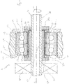
- Figures 1 and 2 show a rotary machine 1 centered on a central axis X1.
- the rotary machine 1 is an electric compressor or a turboexpander used for the extraction of oil or gas in the nature. Most of the parts of the rotary machine 1 operate in a pressurized corrosive medium, for example natural or sour gas.
- the rotary machine 1 comprises a stator assembly 20, a rotor assembly 30, a magnetic bearing 40, and a landing bearing assembly 10.
- the stator assembly 20 comprises a housing (not represented), a compliant tubular bush 23, a lateral holder 22 and a backing device 29.
- the tubular bush 23 is fitted inside the housing.
- the holder 22 and the backing device 29 form means for fastening and preloading a stator landing portion 21 to the stator assembly 20.
- the stator landing portion 21 constitutes a first element of the landing bearing assembly 10.
- the tubular bush 23 has two functions. The first one is to hold tight and to center the stator landing portion 21 with respect to the stator housing. The second function is to dampen vibrations generated inside the rotary machine 1.
- the rotor assembly 30 comprises a (preferably but not necessarily hollow) rotor shaft 31 and a rotor landing portion 32 constituting a second element of the landing bearing assembly 10.
- the landing bearing assembly 10 consists of the stator landing portion 21 integral with the stator assembly 20, and the rotor landing portion 32 integral with the rotor assembly 30. Upon landing of the rotor assembly 30, the stator landing portion 21 and the rotor landing portion 32 come into direct contact with each other.
- the rotor assembly 30 is movable in rotation R1 around axis X1.
- the magnetic bearing 40 is schematically represented on figures 1 and 2 , its arrangement relative to the stator assembly 20 and rotor assembly 30 being not shown, for simplification purpose.
- the magnetic bearing may consist of a radial magnetic bearing, an axial magnetic, or a combination of at least one radial magnetic bearing and one axial magnetic bearing.
- the magnetic bearing is preferably of the active type.
- the landing bearing assembly also known as emergency bearing, back-up bearing or touch down bearing, supports the rotor assembly 30 essentially during a starting or stopping operation of the rotary machine 1, and also during brief intermittent periods in case of shock-loads in the event of a total or partial failure of the magnetic bearing 40.
- one or both of the contacting surfaces of these portions is treated in order to increase its hardness.
- Such treatment consists of one or several coatings.
- the rotary machine 1 equipped with the landing bearing assembly 10 is intended to be used in a very corrosive environment during their whole lifetime, in particular during the extraction and transportation of oil or natural gas.
- the different elements constituting the rotary machine 1 and the landing bearing assembly 10 are intended to be in direct contact with the corrosive environment, typically a sour gas at very high temperature (a few hundred Celsius degrees) and very high pressure (a few hundred bars).
- stator landing portion 21 and the rotor landing portion 32 are made of a corrosion resistance material.
- stator landing portion 21 is made of a high nitrogen steel such as NitroMax.
- stator landing portion 21 comprises a first coating 26 with anti-wear and/or anti-friction properties.
- the first coating is an anti-wear coating, and is made of tungsten carbide or DLC.
- the first coating is an anti-wear coating and is made of alumines in a matrix of titanium.
- a sub-layer of nickel-aluminium alloy is first applied onto the stator landing portion 21.
- the coating made of alumines in a matrix of titanium is then applied directly onto the sub-layer of nickel-aluminium alloy.
- the first coating is an anti-wear coating and is made of tungsten carbide in a matrix of cobalt-chrome.
- the stator landing portion 21 comprises a second coating 27 with anti-wear and/or anti-friction properties.
- the second coating is an anti-wear coating.
- This second coating 27 is preferably made of DLC (Diamond Like Carbon).
- the rotor landing portion 32 is made of a nickel based alloy, preferably an Inconel such as Inconel-718, or an austenitic stainless steel such as Nitronic60, or a hardenable stainless steel such as a martensitic or austenitic high nitrogen stainless steel. In another embodiment, the rotor landing portion 32 is made of a cobalt-based alloy.
- the rotor landing portion 32 comprises a first coating 36 with anti-wear and/or anti-friction properties.
- the first coating 36 is an anti-wear coating, and is made of tungsten carbide or DLC.
- the first coating 36 is made of alumines in a matrix of titanium, and a sub-layer of nickel-aluminium alloy is first applied onto the rotor landing portion 21. The coating made of alumines in a matrix of titanium is then applied directly onto the sub-layer of nickel-aluminium alloy.
- the first coating is an anti-wear coating and is made of tungsten carbide in a matrix of cobalt-chrome.
- the rotor landing portion 32 comprises a second coating 37 with anti-wear and/or anti-friction properties.
- This second coating 37 is preferably made of DLC.
- the different coatings can be applied according to different known methods chosen among thermal spraying, PEPVD or PECVD.
- the coatings can be ceramic based coatings or oxide based coatings. Ceramic coatings such as tungsten carbide in a matrix of cobalt-chrome, onto which a thin layer of DLC is added, are well adapted for resistance against wear and friction.
- each coating is between one and ten tenth of a millimeter.
- coatings are expensive devices, preferably the coatings are dispensed only on the surfaces of the stator landing portion 21 and of the rotor landing portion 21 which come into contact with each other during landing of the rotor shaft 31.
- each coating is preferably also resistant to corrosion, so that the landing bearing assembly can operate in direct contact with a corrosive fluid which can hence advantageously contribute to the cooling of the former without jeopardizing the operation of the landing bearing assembly and hence of the rotary machine.
- both stator landing portion and rotor landing portion made of materials highly resistant to the corrosion, because in the case where the first coating, or the first and second coatings originally present on the stator landing portion and/or the rotor landing portion has been removed upon contact of the landing surfaces in such a way that the material constituting the stator landing portion and rotor landing portion comes in direct contact with the corrosive environment, the landing bearing assembly will still exhibit a high resistant to corrosion.
- the stator landing portion 21 includes two adjacent ball bearings 24 and 25, also known as tandem ball bearings, preloaded and particularly adapted for use in pressurized environment.
- Bearing 24 includes an outer ring 242 and an inner ring 241
- bearing 25 includes an outer ring 252 and an inner ring 251.
- the stator landing portion 21 is a double row angular contact ball bearing.
- the stator landing portion 21 is a pair of single row angular contact bearings.
- Balls 50 are located between the inner ring and the outer ring of each ball bearing 24, 25. Balls 50 may be made of ceramic or steel. Outer rings 242 and 252 are fitted inside tubular bush 23. Lateral holder 22 is positioned against outer ring 242, while backing device 29 is positioned against outer ring 252. Holder 22 and device 29 form means for fastening outer rings 242 and 252 to the stator assembly 20.
- Inner rings 241 and 251 are made from a corrosion resistance material, such as a high nitrogen steel.
- the inner rings are made of NitroMax.
- the inner rings 241and 251 comprise a first coating 26 with anti-wear and/or anti-friction properties.
- the first coating is made of tungsten carbide or DLC.
- the first coating is made of alumines in a matrix of titanium and a sub-layer of nickel-aluminium alloy is first applied.
- the first coating is made of tungsten carbides in a matrix of cobalt-chrome.
- the inner rings 241 and 251 comprise a second coating 27 made of DLC.
- the rotor landing portion 32 consists of a landing sleeve 33 which is installed on the rotor shaft 31.
- the landing sleeve 33 is solidar in rotation with the rotor shaft.
- the landing sleeve 33 is installed on the shaft either by force fitting or by thermal expansion under the effect of temperature.
- the landing sleeve 33 is made from a corrosion resistance material such as Inconel -718.
- the landing sleeve 33 is L-shaped or U-shaped.
- the landing sleeve can consist of a single piece or be made of two pieces.
- the landing sleeve features an axial portion 331 with at one end a first radial portion 332.
- the landing sleeve may also comprise a second radial portion 333.
- the rotor assembly 30 can land safely so as to avoid a not desired uncontrolled and excessive axial displacement of the rotor assembly 30 with respect to the stator assembly 20.
- the landing sleeve 33 comprises a first coating 36 with anti-wear and/or anti-friction properties.
- the first coating 36 is an anti-wear coating, and is made of tungsten carbide or DLC.
- the first coating 36 is made of alumines in a matrix of titanium and a sub-layer of nickel-aluminium alloy is first applied in order to enhance the adherence of the coating.
- the first coating is made of tungsten carbides in a matrix of cobalt-chrome.
- the landing sleeve 33 comprises a second coating 37 made of DLC.
- FIG 2 illustrates another preferred embodiment of the invention where, for the sake of simplicity and clarity, the same elements as illustrated on figure 1 bear the same numeral references.
- the embodiment of figure 2 differs from the one of figure 1 in that the stator landing portion 21 consists of a single ring, and in that the rotor landing portion 32 is not an additional piece such as the landing sleeve described earlier, but instead forms part of the rotor assembly 30, and in particular the rotor shaft 31 itself.
- the rotary machine 1 can be operated with less risk of corrosion of the elements constituting the landing bearing assembly 10. This allows also prolonged maintenance intervals and improved run times. Furthermore, more corrosive fluids can be processed in direct contact with the elements constituting the landing bearing assembly 10, thus avoiding sophisticated solutions such as labyrinths or dry gas seals.
- the landing bearing assembly 10 can be adapted to the specific requirements of the application.
- the stator landing portion 21 consists of a double row angular contact bearing and the rotor landing portion 32 consists of a portion integrally formed with the rotor shaft 31.
- the rotary machine 1 described in details previously is an electric compressor or a turboexpander used for the extraction of oil or gas in the nature.
- the rotary machine 1 may be of any kind adapted for a transportation vehicle, a machine-tool, a household apparatus, etc.
- the rotary machine 1 may be an electric compressor equipping an automotive vehicle.
Landscapes
- Engineering & Computer Science (AREA)
- General Engineering & Computer Science (AREA)
- Mechanical Engineering (AREA)
- Power Engineering (AREA)
- Structures Of Non-Positive Displacement Pumps (AREA)
- Magnetic Bearings And Hydrostatic Bearings (AREA)
- Rolling Contact Bearings (AREA)
- Sliding-Contact Bearings (AREA)
Applications Claiming Priority (1)
| Application Number | Priority Date | Filing Date | Title |
|---|---|---|---|
| DE102016216427 | 2016-08-31 |
Publications (3)
| Publication Number | Publication Date |
|---|---|
| EP3291421A2 true EP3291421A2 (de) | 2018-03-07 |
| EP3291421A3 EP3291421A3 (de) | 2018-03-21 |
| EP3291421B1 EP3291421B1 (de) | 2021-01-20 |
Family
ID=59631589
Family Applications (1)
| Application Number | Title | Priority Date | Filing Date |
|---|---|---|---|
| EP17185719.6A Active EP3291421B1 (de) | 2016-08-31 | 2017-08-10 | Fanglageranordnung und damit und mit einem magnetlager ausgerüstete rotierende maschine |
Country Status (4)
| Country | Link |
|---|---|
| US (1) | US10859115B2 (de) |
| EP (1) | EP3291421B1 (de) |
| CN (1) | CN107786024B (de) |
| CA (1) | CA2970492C (de) |
Families Citing this family (6)
| Publication number | Priority date | Publication date | Assignee | Title |
|---|---|---|---|---|
| US11274705B2 (en) * | 2016-02-19 | 2022-03-15 | Johnson Controls Technology Company | Vapor compression system and method of extending service life of same |
| US11619266B2 (en) | 2018-02-26 | 2023-04-04 | Roller Bearing Company Of America, Inc. | Self lubricating titanium aluminide composite material |
| CN109687627A (zh) * | 2018-11-15 | 2019-04-26 | 江苏无线电厂有限公司 | 一种外转子直流无刷电机及动力系统 |
| US11566663B2 (en) | 2019-06-26 | 2023-01-31 | Trane International Inc. | Bearing for supporting a rotating compressor shaft |
| CN112412987A (zh) * | 2020-11-27 | 2021-02-26 | 江苏当升智能装备科技有限公司 | 一种用于智能设备中瓦座的加油方法 |
| CN117231627A (zh) * | 2023-09-21 | 2023-12-15 | 洛阳轴承研究所有限公司 | 一种磁悬浮主轴保护用角接触球轴承组件 |
Citations (1)
| Publication number | Priority date | Publication date | Assignee | Title |
|---|---|---|---|---|
| US7847454B2 (en) | 2007-03-08 | 2010-12-07 | General Electric Company | Encapsulated stator assembly and process for making |
Family Cites Families (20)
| Publication number | Priority date | Publication date | Assignee | Title |
|---|---|---|---|---|
| US3794334A (en) * | 1970-05-11 | 1974-02-26 | Ramsey Corp | Piston ring facings |
| US6004372A (en) * | 1999-01-28 | 1999-12-21 | Praxair S.T. Technology, Inc. | Thermal spray coating for gates and seats |
| US6139261A (en) * | 1999-04-16 | 2000-10-31 | General Electric Company | Bushing assembly with removable wear sleeve |
| US6987339B2 (en) * | 2002-05-03 | 2006-01-17 | Honeywell International, Inc. | Flywheel secondary bearing with rhenium or rhenium alloy coating |
| AT413034B (de) * | 2003-10-08 | 2005-10-15 | Miba Gleitlager Gmbh | Legierung, insbesondere für eine gleitschicht |
| US6986647B2 (en) * | 2003-11-21 | 2006-01-17 | Tokyo Electron Limited | Pump design for circulating supercritical carbon dioxide |
| US7367890B2 (en) * | 2004-06-12 | 2008-05-06 | Wanxiang Qianchao Co., Ltd. | Yoke-trunnion universal joint without needle bearings |
| AT502630B1 (de) * | 2005-10-21 | 2008-01-15 | Miba Sinter Austria Gmbh | Bauelement, insbesondere formteil, mit einer beschichtung |
| DE102006049974A1 (de) * | 2006-10-24 | 2008-04-30 | Oerlikon Leybold Vacuum Gmbh | Turbomaschine |
| US20080145649A1 (en) * | 2006-12-14 | 2008-06-19 | General Electric | Protective coatings which provide wear resistance and low friction characteristics, and related articles and methods |
| US20080219834A1 (en) | 2007-03-08 | 2008-09-11 | General Electric Company | Rotor Shaft Assembly for Magnetic Bearings for Use in Corrosive Environments |
| US8875380B2 (en) * | 2007-03-08 | 2014-11-04 | General Electric Company | Process of forming an encapsulated magnet assembly |
| US20080218008A1 (en) | 2007-03-08 | 2008-09-11 | General Electric Company | Rotor and Stator Assemblies that Utilize Magnetic Bearings for Use in Corrosive Environments |
| WO2014098005A1 (ja) * | 2012-12-19 | 2014-06-26 | Ntn株式会社 | フォイル軸受 |
| EP2803875B1 (de) * | 2013-05-13 | 2019-03-13 | Aktiebolaget SKF | Landungslager und magnetische Lageranordnung |
| EP2803874B1 (de) * | 2013-05-13 | 2019-08-14 | Aktiebolaget SKF | Landungslager und magnetische Lageranordnung |
| EP2808573B1 (de) * | 2013-05-29 | 2019-03-13 | Skf Magnetic Mechatronics | Hilfslager für magnetisch aufgehängtes Rotorsystem |
| EP2918845B2 (de) * | 2014-03-11 | 2022-01-12 | Skf Magnetic Mechatronics | Rotationsmaschine, Lager und Verfahren zur Herstellung einer Rotationsmaschine |
| CN108431290B (zh) * | 2015-11-10 | 2021-03-23 | 欧瑞康表面处理解决方案股份公司普费菲孔 | 涡轮间隙控制涂层和方法 |
| EP3327302B1 (de) * | 2016-11-28 | 2019-11-13 | Skf Magnetic Mechatronics | Landungslageranordnung und mit solch einer anordnung ausgerüstete drehmaschine |
-
2017
- 2017-06-13 CA CA2970492A patent/CA2970492C/en active Active
- 2017-07-26 CN CN201710617299.9A patent/CN107786024B/zh active Active
- 2017-08-10 EP EP17185719.6A patent/EP3291421B1/de active Active
- 2017-08-22 US US15/682,950 patent/US10859115B2/en active Active
Patent Citations (1)
| Publication number | Priority date | Publication date | Assignee | Title |
|---|---|---|---|---|
| US7847454B2 (en) | 2007-03-08 | 2010-12-07 | General Electric Company | Encapsulated stator assembly and process for making |
Also Published As
| Publication number | Publication date |
|---|---|
| US10859115B2 (en) | 2020-12-08 |
| EP3291421A3 (de) | 2018-03-21 |
| CA2970492A1 (en) | 2018-02-28 |
| US20180128315A1 (en) | 2018-05-10 |
| CN107786024B (zh) | 2022-02-08 |
| CA2970492C (en) | 2026-02-10 |
| EP3291421B1 (de) | 2021-01-20 |
| CN107786024A (zh) | 2018-03-09 |
Similar Documents
| Publication | Publication Date | Title |
|---|---|---|
| EP3291421B1 (de) | Fanglageranordnung und damit und mit einem magnetlager ausgerüstete rotierende maschine | |
| CN112513402B (zh) | 多晶金刚石向心轴承 | |
| JP5261664B2 (ja) | 真空ポンプ | |
| US10408086B1 (en) | Turbine assembly including at least one superhard bearing | |
| US5073036A (en) | Hydrostatic bearing for axial/radial support | |
| EP2567072B1 (de) | Dichtbuchsengehäuse mit bürstenringdichtung | |
| US10385921B2 (en) | Combination bearing and seal assembly for rotatable shafts | |
| EP3284926B1 (de) | Turbolader | |
| JP2014077522A (ja) | 軸受 | |
| EP2037135B1 (de) | Wälzlager, Streben und Gasturbinenmotoren damit | |
| EP3262268B1 (de) | Dichtungsanordnungen für erdbohrmeissel, bohrmeissel damit und zugehörige verfahren | |
| JP2005315392A (ja) | 高速回転機器用ガスシール | |
| US20170058954A1 (en) | Shaft seal having transitional contact | |
| JP4640003B2 (ja) | スラストニードル軸受を備えた回転支持部 | |
| JP2006118696A (ja) | スラストころ軸受 | |
| EP3009697A1 (de) | Wälzlageranordnung und Drehmaschine mit solch einer Wälzlageranordnung | |
| JP2008223806A (ja) | タッチダウン軸受 | |
| JP4758884B2 (ja) | 高速回転機器用ガスシール装置 | |
| JP2007285445A (ja) | 固体潤滑転がり軸受 | |
| US20160281434A1 (en) | Seal assembly and a roller cone drill bit comprising such a seal assembly |
Legal Events
| Date | Code | Title | Description |
|---|---|---|---|
| PUAI | Public reference made under article 153(3) epc to a published international application that has entered the european phase |
Free format text: ORIGINAL CODE: 0009012 |
|
| STAA | Information on the status of an ep patent application or granted ep patent |
Free format text: STATUS: THE APPLICATION HAS BEEN PUBLISHED |
|
| PUAL | Search report despatched |
Free format text: ORIGINAL CODE: 0009013 |
|
| AK | Designated contracting states |
Kind code of ref document: A2 Designated state(s): AL AT BE BG CH CY CZ DE DK EE ES FI FR GB GR HR HU IE IS IT LI LT LU LV MC MK MT NL NO PL PT RO RS SE SI SK SM TR |
|
| AX | Request for extension of the european patent |
Extension state: BA ME |
|
| AK | Designated contracting states |
Kind code of ref document: A3 Designated state(s): AL AT BE BG CH CY CZ DE DK EE ES FI FR GB GR HR HU IE IS IT LI LT LU LV MC MK MT NL NO PL PT RO RS SE SI SK SM TR |
|
| AX | Request for extension of the european patent |
Extension state: BA ME |
|
| RIC1 | Information provided on ipc code assigned before grant |
Ipc: H02K 7/09 20060101AFI20180212BHEP Ipc: F16C 32/04 20060101ALI20180212BHEP |
|
| STAA | Information on the status of an ep patent application or granted ep patent |
Free format text: STATUS: REQUEST FOR EXAMINATION WAS MADE |
|
| 17P | Request for examination filed |
Effective date: 20180830 |
|
| RBV | Designated contracting states (corrected) |
Designated state(s): AL AT BE BG CH CY CZ DE DK EE ES FI FR GB GR HR HU IE IS IT LI LT LU LV MC MK MT NL NO PL PT RO RS SE SI SK SM TR |
|
| GRAP | Despatch of communication of intention to grant a patent |
Free format text: ORIGINAL CODE: EPIDOSNIGR1 |
|
| STAA | Information on the status of an ep patent application or granted ep patent |
Free format text: STATUS: GRANT OF PATENT IS INTENDED |
|
| RIC1 | Information provided on ipc code assigned before grant |
Ipc: F16C 32/04 20060101ALI20200708BHEP Ipc: F16C 35/077 20060101ALI20200708BHEP Ipc: H02K 7/09 20060101AFI20200708BHEP Ipc: F16C 35/073 20060101ALI20200708BHEP |
|
| INTG | Intention to grant announced |
Effective date: 20200810 |
|
| GRAS | Grant fee paid |
Free format text: ORIGINAL CODE: EPIDOSNIGR3 |
|
| GRAA | (expected) grant |
Free format text: ORIGINAL CODE: 0009210 |
|
| STAA | Information on the status of an ep patent application or granted ep patent |
Free format text: STATUS: THE PATENT HAS BEEN GRANTED |
|
| AK | Designated contracting states |
Kind code of ref document: B1 Designated state(s): AL AT BE BG CH CY CZ DE DK EE ES FI FR GB GR HR HU IE IS IT LI LT LU LV MC MK MT NL NO PL PT RO RS SE SI SK SM TR |
|
| REG | Reference to a national code |
Ref country code: GB Ref legal event code: FG4D |
|
| REG | Reference to a national code |
Ref country code: CH Ref legal event code: EP |
|
| REG | Reference to a national code |
Ref country code: DE Ref legal event code: R096 Ref document number: 602017031585 Country of ref document: DE |
|
| REG | Reference to a national code |
Ref country code: AT Ref legal event code: REF Ref document number: 1357198 Country of ref document: AT Kind code of ref document: T Effective date: 20210215 |
|
| REG | Reference to a national code |
Ref country code: IE Ref legal event code: FG4D |
|
| REG | Reference to a national code |
Ref country code: NO Ref legal event code: T2 Effective date: 20210120 |
|
| REG | Reference to a national code |
Ref country code: NL Ref legal event code: MP Effective date: 20210120 |
|
| REG | Reference to a national code |
Ref country code: LT Ref legal event code: MG9D |
|
| REG | Reference to a national code |
Ref country code: AT Ref legal event code: MK05 Ref document number: 1357198 Country of ref document: AT Kind code of ref document: T Effective date: 20210120 |
|
| PG25 | Lapsed in a contracting state [announced via postgrant information from national office to epo] |
Ref country code: PT Free format text: LAPSE BECAUSE OF FAILURE TO SUBMIT A TRANSLATION OF THE DESCRIPTION OR TO PAY THE FEE WITHIN THE PRESCRIBED TIME-LIMIT Effective date: 20210520 Ref country code: FI Free format text: LAPSE BECAUSE OF FAILURE TO SUBMIT A TRANSLATION OF THE DESCRIPTION OR TO PAY THE FEE WITHIN THE PRESCRIBED TIME-LIMIT Effective date: 20210120 Ref country code: HR Free format text: LAPSE BECAUSE OF FAILURE TO SUBMIT A TRANSLATION OF THE DESCRIPTION OR TO PAY THE FEE WITHIN THE PRESCRIBED TIME-LIMIT Effective date: 20210120 Ref country code: GR Free format text: LAPSE BECAUSE OF FAILURE TO SUBMIT A TRANSLATION OF THE DESCRIPTION OR TO PAY THE FEE WITHIN THE PRESCRIBED TIME-LIMIT Effective date: 20210421 Ref country code: LT Free format text: LAPSE BECAUSE OF FAILURE TO SUBMIT A TRANSLATION OF THE DESCRIPTION OR TO PAY THE FEE WITHIN THE PRESCRIBED TIME-LIMIT Effective date: 20210120 Ref country code: BG Free format text: LAPSE BECAUSE OF FAILURE TO SUBMIT A TRANSLATION OF THE DESCRIPTION OR TO PAY THE FEE WITHIN THE PRESCRIBED TIME-LIMIT Effective date: 20210420 |
|
| PG25 | Lapsed in a contracting state [announced via postgrant information from national office to epo] |
Ref country code: PL Free format text: LAPSE BECAUSE OF FAILURE TO SUBMIT A TRANSLATION OF THE DESCRIPTION OR TO PAY THE FEE WITHIN THE PRESCRIBED TIME-LIMIT Effective date: 20210120 Ref country code: RS Free format text: LAPSE BECAUSE OF FAILURE TO SUBMIT A TRANSLATION OF THE DESCRIPTION OR TO PAY THE FEE WITHIN THE PRESCRIBED TIME-LIMIT Effective date: 20210120 Ref country code: LV Free format text: LAPSE BECAUSE OF FAILURE TO SUBMIT A TRANSLATION OF THE DESCRIPTION OR TO PAY THE FEE WITHIN THE PRESCRIBED TIME-LIMIT Effective date: 20210120 Ref country code: AT Free format text: LAPSE BECAUSE OF FAILURE TO SUBMIT A TRANSLATION OF THE DESCRIPTION OR TO PAY THE FEE WITHIN THE PRESCRIBED TIME-LIMIT Effective date: 20210120 Ref country code: SE Free format text: LAPSE BECAUSE OF FAILURE TO SUBMIT A TRANSLATION OF THE DESCRIPTION OR TO PAY THE FEE WITHIN THE PRESCRIBED TIME-LIMIT Effective date: 20210120 |
|
| PG25 | Lapsed in a contracting state [announced via postgrant information from national office to epo] |
Ref country code: IS Free format text: LAPSE BECAUSE OF FAILURE TO SUBMIT A TRANSLATION OF THE DESCRIPTION OR TO PAY THE FEE WITHIN THE PRESCRIBED TIME-LIMIT Effective date: 20210520 |
|
| REG | Reference to a national code |
Ref country code: DE Ref legal event code: R097 Ref document number: 602017031585 Country of ref document: DE |
|
| PG25 | Lapsed in a contracting state [announced via postgrant information from national office to epo] |
Ref country code: SM Free format text: LAPSE BECAUSE OF FAILURE TO SUBMIT A TRANSLATION OF THE DESCRIPTION OR TO PAY THE FEE WITHIN THE PRESCRIBED TIME-LIMIT Effective date: 20210120 Ref country code: EE Free format text: LAPSE BECAUSE OF FAILURE TO SUBMIT A TRANSLATION OF THE DESCRIPTION OR TO PAY THE FEE WITHIN THE PRESCRIBED TIME-LIMIT Effective date: 20210120 Ref country code: CZ Free format text: LAPSE BECAUSE OF FAILURE TO SUBMIT A TRANSLATION OF THE DESCRIPTION OR TO PAY THE FEE WITHIN THE PRESCRIBED TIME-LIMIT Effective date: 20210120 |
|
| PLBE | No opposition filed within time limit |
Free format text: ORIGINAL CODE: 0009261 |
|
| STAA | Information on the status of an ep patent application or granted ep patent |
Free format text: STATUS: NO OPPOSITION FILED WITHIN TIME LIMIT |
|
| PG25 | Lapsed in a contracting state [announced via postgrant information from national office to epo] |
Ref country code: DK Free format text: LAPSE BECAUSE OF FAILURE TO SUBMIT A TRANSLATION OF THE DESCRIPTION OR TO PAY THE FEE WITHIN THE PRESCRIBED TIME-LIMIT Effective date: 20210120 Ref country code: RO Free format text: LAPSE BECAUSE OF FAILURE TO SUBMIT A TRANSLATION OF THE DESCRIPTION OR TO PAY THE FEE WITHIN THE PRESCRIBED TIME-LIMIT Effective date: 20210120 Ref country code: SK Free format text: LAPSE BECAUSE OF FAILURE TO SUBMIT A TRANSLATION OF THE DESCRIPTION OR TO PAY THE FEE WITHIN THE PRESCRIBED TIME-LIMIT Effective date: 20210120 |
|
| 26N | No opposition filed |
Effective date: 20211021 |
|
| PG25 | Lapsed in a contracting state [announced via postgrant information from national office to epo] |
Ref country code: AL Free format text: LAPSE BECAUSE OF FAILURE TO SUBMIT A TRANSLATION OF THE DESCRIPTION OR TO PAY THE FEE WITHIN THE PRESCRIBED TIME-LIMIT Effective date: 20210120 Ref country code: ES Free format text: LAPSE BECAUSE OF FAILURE TO SUBMIT A TRANSLATION OF THE DESCRIPTION OR TO PAY THE FEE WITHIN THE PRESCRIBED TIME-LIMIT Effective date: 20210120 |
|
| PG25 | Lapsed in a contracting state [announced via postgrant information from national office to epo] |
Ref country code: SI Free format text: LAPSE BECAUSE OF FAILURE TO SUBMIT A TRANSLATION OF THE DESCRIPTION OR TO PAY THE FEE WITHIN THE PRESCRIBED TIME-LIMIT Effective date: 20210120 |
|
| PG25 | Lapsed in a contracting state [announced via postgrant information from national office to epo] |
Ref country code: MC Free format text: LAPSE BECAUSE OF FAILURE TO SUBMIT A TRANSLATION OF THE DESCRIPTION OR TO PAY THE FEE WITHIN THE PRESCRIBED TIME-LIMIT Effective date: 20210120 |
|
| REG | Reference to a national code |
Ref country code: BE Ref legal event code: MM Effective date: 20210831 |
|
| GBPC | Gb: european patent ceased through non-payment of renewal fee |
Effective date: 20210810 |
|
| PG25 | Lapsed in a contracting state [announced via postgrant information from national office to epo] |
Ref country code: IS Free format text: LAPSE BECAUSE OF FAILURE TO SUBMIT A TRANSLATION OF THE DESCRIPTION OR TO PAY THE FEE WITHIN THE PRESCRIBED TIME-LIMIT Effective date: 20210520 Ref country code: LU Free format text: LAPSE BECAUSE OF NON-PAYMENT OF DUE FEES Effective date: 20210810 |
|
| PG25 | Lapsed in a contracting state [announced via postgrant information from national office to epo] |
Ref country code: IE Free format text: LAPSE BECAUSE OF NON-PAYMENT OF DUE FEES Effective date: 20210810 Ref country code: GB Free format text: LAPSE BECAUSE OF NON-PAYMENT OF DUE FEES Effective date: 20210810 Ref country code: BE Free format text: LAPSE BECAUSE OF NON-PAYMENT OF DUE FEES Effective date: 20210831 |
|
| PG25 | Lapsed in a contracting state [announced via postgrant information from national office to epo] |
Ref country code: HU Free format text: LAPSE BECAUSE OF FAILURE TO SUBMIT A TRANSLATION OF THE DESCRIPTION OR TO PAY THE FEE WITHIN THE PRESCRIBED TIME-LIMIT; INVALID AB INITIO Effective date: 20170810 |
|
| P01 | Opt-out of the competence of the unified patent court (upc) registered |
Effective date: 20230514 |
|
| PG25 | Lapsed in a contracting state [announced via postgrant information from national office to epo] |
Ref country code: NL Free format text: LAPSE BECAUSE OF NON-PAYMENT OF DUE FEES Effective date: 20210120 Ref country code: CY Free format text: LAPSE BECAUSE OF FAILURE TO SUBMIT A TRANSLATION OF THE DESCRIPTION OR TO PAY THE FEE WITHIN THE PRESCRIBED TIME-LIMIT Effective date: 20210120 |
|
| PG25 | Lapsed in a contracting state [announced via postgrant information from national office to epo] |
Ref country code: MK Free format text: LAPSE BECAUSE OF FAILURE TO SUBMIT A TRANSLATION OF THE DESCRIPTION OR TO PAY THE FEE WITHIN THE PRESCRIBED TIME-LIMIT Effective date: 20210120 |
|
| PG25 | Lapsed in a contracting state [announced via postgrant information from national office to epo] |
Ref country code: TR Free format text: LAPSE BECAUSE OF FAILURE TO SUBMIT A TRANSLATION OF THE DESCRIPTION OR TO PAY THE FEE WITHIN THE PRESCRIBED TIME-LIMIT Effective date: 20210120 |
|
| PG25 | Lapsed in a contracting state [announced via postgrant information from national office to epo] |
Ref country code: MT Free format text: LAPSE BECAUSE OF FAILURE TO SUBMIT A TRANSLATION OF THE DESCRIPTION OR TO PAY THE FEE WITHIN THE PRESCRIBED TIME-LIMIT Effective date: 20210120 |
|
| PGFP | Annual fee paid to national office [announced via postgrant information from national office to epo] |
Ref country code: DE Payment date: 20250827 Year of fee payment: 9 |
|
| PGFP | Annual fee paid to national office [announced via postgrant information from national office to epo] |
Ref country code: NO Payment date: 20250819 Year of fee payment: 9 |
|
| PGFP | Annual fee paid to national office [announced via postgrant information from national office to epo] |
Ref country code: IT Payment date: 20250825 Year of fee payment: 9 |
|
| PGFP | Annual fee paid to national office [announced via postgrant information from national office to epo] |
Ref country code: FR Payment date: 20250825 Year of fee payment: 9 |
|
| PGFP | Annual fee paid to national office [announced via postgrant information from national office to epo] |
Ref country code: CH Payment date: 20250901 Year of fee payment: 9 |