EP3291601B1 - Procédé d'allocation de ressources d'un système de communication sans fil et son mécanisme - Google Patents
Procédé d'allocation de ressources d'un système de communication sans fil et son mécanisme Download PDFInfo
- Publication number
- EP3291601B1 EP3291601B1 EP17189126.0A EP17189126A EP3291601B1 EP 3291601 B1 EP3291601 B1 EP 3291601B1 EP 17189126 A EP17189126 A EP 17189126A EP 3291601 B1 EP3291601 B1 EP 3291601B1
- Authority
- EP
- European Patent Office
- Prior art keywords
- bbu
- rrh
- controller
- orchestrator
- resource
- Prior art date
- Legal status (The legal status is an assumption and is not a legal conclusion. Google has not performed a legal analysis and makes no representation as to the accuracy of the status listed.)
- Active
Links
Images



Classifications
-
- H—ELECTRICITY
- H04—ELECTRIC COMMUNICATION TECHNIQUE
- H04W—WIRELESS COMMUNICATION NETWORKS
- H04W28/00—Network traffic management; Network resource management
- H04W28/16—Central resource management; Negotiation of resources or communication parameters, e.g. negotiating bandwidth or QoS [Quality of Service]
-
- H—ELECTRICITY
- H04—ELECTRIC COMMUNICATION TECHNIQUE
- H04W—WIRELESS COMMUNICATION NETWORKS
- H04W72/00—Local resource management
- H04W72/20—Control channels or signalling for resource management
- H04W72/23—Control channels or signalling for resource management in the downlink direction of a wireless link, i.e. towards a terminal
-
- H—ELECTRICITY
- H04—ELECTRIC COMMUNICATION TECHNIQUE
- H04W—WIRELESS COMMUNICATION NETWORKS
- H04W72/00—Local resource management
- H04W72/50—Allocation or scheduling criteria for wireless resources
- H04W72/53—Allocation or scheduling criteria for wireless resources based on regulatory allocation policies
-
- H—ELECTRICITY
- H04—ELECTRIC COMMUNICATION TECHNIQUE
- H04W—WIRELESS COMMUNICATION NETWORKS
- H04W88/00—Devices specially adapted for wireless communication networks, e.g. terminals, base stations or access point devices
- H04W88/08—Access point devices
- H04W88/085—Access point devices with remote components
Definitions
- the present disclosure relates generally to the field of wireless communication, and pertains particularly to a resource allocation method of a wireless communication system and mechanism thereof.
- WO 2016/054183 A1 discloses an apparatus includes a monitor module configured to monitor a set of performance indicators associated with a first network topology of a wireless network provider system. In the first network topology, a set of virtual baseband units services a set of remote radio heads.
- the apparatus includes a detector module configured to detect an operational condition of the wireless network provider system based on at least one value associated with the set of performance indicators at a first time.
- the apparatus further includes an optimization module configured to define, based on the operational condition, a second network topology for the set of virtual baseband units.
- the optimization module is further configured to send a signal to a virtual baseband unit pool manager to configure the wireless network provider system in the second network topology at a second time after the first time.
- Document US2015/0256358 discloses a system for routing signals in a Distributed Antenna System including Digital Multiplexing Units, Baseband Units and Digital Remote Units.
- Document EP2512202 discloses a concept for load balancing in a mobile communication network where traffic is routed between baseband units and remote radio heads.
- a method of resource allocation implemented in a wireless communication system includes the following steps. At least one resource allocation instruction is received by an orchestrator. A remote radio head (RRH) resource allocation request, a fronthaul (FH) resource allocation request, and a baseband unit (BBU) resource allocation request are generated by the orchestrator, in response to the at least one resource allocation instruction.
- the RRH resource allocation request is transmitted, by the orchestrator, to an RRH pool
- the FH resource allocation request is transmitted, by the orchestrator, to an FH network
- the BBU resource allocation request is transmitted, by the orchestrator, to a BBU pool.
- An RRH resource is allocated by an RRH controller of the RRH pool in response to the RRH resource allocation request, and RRH allocation information of the allocated RRH resource is transmitted to the orchestrator.
- An FH network resource is allocated by an FH controller of the FH network in response to the FH resource allocation request, and FH allocation information of the allocated FH network resource is transmitted to the orchestrator.
- a BBU resource is allocated by a BBU controller of the BBU pool in response to the BBU resource allocation request, and BBU allocation information of the allocated BBU resource is transmitted to the orchestrator.
- a data path including at least one RRH in the RRH pool, the FH network and at least one BBU in the BBU pool is established by the orchestrator in response to the RRH allocation information, the FH allocation information and the BBU allocation information.
- a method of resource allocation implemented in an electronic equipment includes the following steps. At least one resource allocation instruction is received by an orchestrator. An RRH resource allocation request, an FH resource allocation request, and a BBU resource allocation request are generated by the orchestrator in response to the at least one resource allocation instruction. The RRH resource allocation request is transmitted, by the orchestrator, to an RRH pool, the FH resource allocation request is transmitted, by the orchestrator, to an FH network and the BBU resource allocation request is transmitted, by the orchestrator, to a BBU pool. RRH allocation information of an allocated RRH resource is received, by the orchestrator, from an RRH controller of the RRH pool.
- FH allocation information of an allocated FH network resource is received, by the orchestrator, from an FH controller of the FH network.
- BBU allocation information of an allocated BBU resource is received, by the orchestrator, from a BBU controller of the BBU pool.
- a data path including at least one RRH in the RRH pool, the FH network and at least one BBU in the BBU pool is established by the orchestrator in response to the RRH allocation information, the FH allocation information and the BBU allocation information.
- an electronic equipment of a wireless communication system includes an orchestrator respectively coupled to an FH network, an RRH pool, and a BBU pool.
- the orchestrator is configured to establish a data path in response to RRH allocation information, FH allocation information and BBU allocation information.
- the data path includes at least one RRH in the RRH pool, the FH network and at least one BBU in the BBU pool.
- a BBU resource allocation system includes a BBU controller and a plurality of BBUs.
- the BBUs coupled to the BBU controller.
- the BBU controller is configured to receive a BBU resource allocation request from an electronic equipment.
- the electronic equipment is respectively coupled to an FH network and an RRH pool.
- the BBU controller is further configured to allocate a BBU resource in response to the BBU resource allocation request, and transmit BBU allocation information to the electronic equipment in response to the allocated BBU resource.
- Coupled is defined as connected, whether directly or indirectly through intervening components, and is not necessarily limited to physical connections.
- the connection can be such that the objects are permanently connected or releasably connected.
- outer refers to a region that is beyond the outermost confines of a physical object.
- inside indicates that at least a portion of a region is partially contained within a boundary formed by the object.
- substantially is defined to be essentially conforming to the particular dimension, shape or other word that substantially modifies, such that the component need not be exact. For example, substantially cylindrical means that the object resembles a cylinder, but can have one or more deviations from a true cylinder.
- comprising means “including, but not necessarily limited to”; it specifically indicates open-ended inclusion or membership in a so-described combination, group, series and the like.
- the present disclosure is described in relation to a wireless communication system having resources allocation mechanism and method thereof.
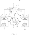
- FIG. 1 shows a wireless communication system 100, in accordance with one embodiment of the present disclosure.
- the wireless communication system 100 includes an RRH pool 11, a BBU pool 12, and an electronic equipment 14.
- the electronic equipment 14 is configured to allocate resources of the wireless communication system 100.
- the RRH pool 11 is coupled to the BBU pool 12 through an FH network 13.
- the RRH pool 11 includes a plurality of RRHs 110 respectively coupled to an RRH controller 112.
- the BBU pool 12 includes a plurality of BBUs 121 respectively coupled to a BBU controller 124.
- the FH network 13 includes an FH controller 131.
- the electronic equipment 14 includes an orchestrator 141 which is coupled to the FH network 13, the RRH pool 11, and the BBU pool 12.
- the orchestrator 141 in the present exemplary embodiment, is configured to generate, in response to at least one resource allocation instruction S in , from a user equipment, an RRH resource allocation request S RRH to the RRH pool 11 to allocate an RRH resource of the RRH pool 11, an FH resource allocation request S FH to the FH network 13 to allocate a FH network resource of the FH network 13, and a BBU resource allocation request S BBU to the BBU pool 12 to allocate a BBU resource of the BBU pool 12.
- the RRH controller 112 in the present exemplary embodiment, is configured to generate RRH allocation information I RRH in response to the allocated RRH resource.
- the FH controller 131 is configured to generate FH allocation information I FH in response to the allocated FH network resource.
- the BBU controller 124 is configured to generate BBU allocation information I BBU in response to the allocated BBU resource.
- FIG. 2 shows a method of resource allocation implemented in the wireless communication system of FIG. 1 of the present disclosure.
- step S210 at least one resource allocation instruction S in is received by the orchestrator 141.
- step S220 the RRH resource allocation request S RRH , the FH resource allocation request S FH , and the BBU resource allocation request S BBU are generated by the orchestrator 141 in response to the at least one resource allocation instruction S in .
- step S230 the RRH resource allocation request S RRH is transmitted, by the orchestrator 141, to the RRH pool 11, the FH resource allocation request S FH is transmitted, by the orchestrator 141, the FH network 13, and the BBU resource allocation request S BBU is transmitted, by the orchestrator 141, to the BBU pool 12.
- step S240 is then performed.
- the RRH resource is allocated by the RRH controller 112 of the RRH pool 11 in response to the RRH resource allocation request S RRH , and the RRH allocation information I RRH of the allocated RRH resource is transmitted to the orchestrator 141.
- the FH resource allocation request S FH is received by the FH controller 131
- the FH network resource is allocated by the FH controller 131 of the FH network 13 in response to the FH resource allocation request S FH , and the FH allocation information I FH of the allocated FH network resource is transmitted to the orchestrator 141.
- step S240 the BBU resource is allocated by the BBU controller 124 of the BBU pool 12 in response to the BBU resource allocation request S BBU , and the BBU allocation information I BBU of the allocated BBU resource is transmitted to the orchestrator 141.
- step S250 a data path including at least one RRH 110 in the RRH pool 11, the FH network 13 and at least one BBU 121 in the BBU pool 12 is established by the orchestrator 141 in response to the RRH allocation information I RRH , the FH allocation information I FH and the BBU allocation information I BBU .
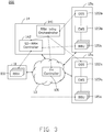
- FIG. 3 illustrates a wireless communication system architecture of a radio access network having a radio over Ethernet (RoE) control mechanism of one embodiment of the present disclosure.
- the wireless communication system 200 of a radio access network adopts an electronic equipment.
- the solid connection lines indicate physical network connections (e.g. wired or wireless), while the dotted lines represent software interfaces and the corresponding hardware implementations thereof.
- the wireless communication system 200 in the present exemplary embodiment, includes the RRH pool 11, a plurality of BBU pools 12a and 12b, and the electronic equipment 14.
- the BBU pools 12a and 12b are communicatively coupled to the electronic equipment 14 and the RRH pool 11 through the shared fronthaul network 13.
- the RRH pool 11 and the electronic equipment 14 may be supported by an RRH network provider.
- the RRH pool 11, in the present exemplary embodiment, comprises a plurality of remote radio heads (e.g., RRHs 110), which may be physically and functionally identical remote radio transceiver units.
- Each of the BBU pools 12a/12b includes a plurality of BBUs 121a/121b, an Operation Support System (OSS) 122a/122b, and an Element Management System (EMS) 123a/123b.
- the BBUs 121a/121b are controllably coupled to the respective EMS 123a/123b through connection that implement suitable software interfaces.
- Each of the EMS 123a/123b is controllably coupled to the respective OSS 122a/122b through suitable hardware and/or software interfaces.
- each of the BBU pools 12a/12b is owned or operated by an individual mobile network operator (MNO), and concurrently share the infrastructures and resources of the RRH pool 11 through the implementation of the electronic equipment 14 and the SDN-equipped fronthaul network (e.g., FH controller 131).
- MNO mobile network operator
- BBU pool 12a and BBU pool 12b are supported by the same mobile network operator. In some other embodiments, BBU pool 12a and BBU pool 12b are supported by different mobile network operators.
- the shared fronthaul network 13 incorporates a software defined FH controller 131 which is capable of managing the fronthaul network resources.
- Each of the BBU pools 12a and 12b is coupled to the RRH pool 11 through the shared fronthaul network 13.
- Each of the BBU pools 12a and 12b is coupled to the shared fronthaul network 13.
- the RRH pool 11 includes physical network connections including wired links, wireless links, and a suitable combination thereof.
- the electronic equipment 14 is connected to the shared fronthaul network 13.
- the electronic equipment 14 is further communicatively coupled to the BBU pools 12a and 12b and the RRH pool 11.
- the electronic equipment 14 comprises an RRH infrastructure orchestrator 141 (hereinafter referred to as an orchestrator) and a software defined RRH (SD-RRH) controller 142.
- the orchestrator 141 is communicatively coupled to the SD-RRH controller 142 through a software interface OCP-NBI (ORI C&M Protocol Northbound API).
- the orchestrator 141 is coupled to the OSSs 122a and 122b of the BBU pools 12a and 12b, respectively, through software interfaces EMS-NBIs (EMS Northbound API).
- the orchestrator 141 in the present exemplary embodiment, is coupled to the FH controller 131 through a software interface OF-NBI (OpenFlow Northbound API).
- the orchestrator 141 is configured to receive resource allocation instructions from a user equipment and generate resource allocation requests to the SD-RRH controller 142, FH controller 131, and the OSS 122a/122b accordingly.
- the SD-RRH controller 142 is communicatively coupled to the RRH pool 11 and the BBUs 121a and 121b of the respective BBU pools 12a and 12b through software interfaces OCP-SBIs. Therefore, a software defined virtual RRH can be dynamically assigned to different BBUs of multiple individual BBU pools (e.g., operated by different Mobile Network Operators (MNOs)).
- MNOs Mobile Network Operators
- the software interface EMS-NBI (based on 3GPP or TM Forum model) includes communication interfaces which allow the OSS (e.g., 122a/122b) to communicate with the orchestrator 141.
- This software interface EMS-NBI enables the OSS (e.g., 122a/122b) to request the RRH infra network resources from the orchestrator 141.
- the software interface OCP-NBI includes communication interfaces between the orchestrator 141 to the SD-RRH controller 142.
- the software interface OCP-NBI is communicatively linked to a northbound interface of the SD-RRH controller 142 and allows the orchestrator 141 to communicate with the SD-RRH controller 142.
- the software interface OF-NBI includes communication interfaces which allow the orchestrator 141 to communicate with the FH controller 131.
- the software interface OF-NBI is communicatively linked to a communication interface of the FH controller 131 and allows the orchestrator 141 to communicate with the FH controller 131.
- the software interface OCP-SBI includes communication interfaces between the SD-RRH controller 142 and the RRH pool 11.
- the software interface OCP-SBI enables the SD-RRH controller 142 to issue RRH configurations and setup resource allocation in the RRH pool 11.
- the software interface OCP-SBI comprises communication interfaces between the SD-RRH controller 142 and the BBUs 121a and 121b of the respective BBU pools 12a and 12b.
- the software interface OCP-SBI enables the SD-RRH controller 142 to communicate with the BBUs for RRH C&M (Control & Management) executions through a southbound interface thereof.
- the FH network 13 can be shared by different mobile network operators, which in turn enables dynamic sharing of RRH pool 11 between different BBU pools (e.g., BBU pools 12a and 12b). Accordingly, the present architecture in accordance with the present disclosure may achieve more flexible and cost-effective RAN sharing among different MNOs.
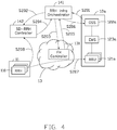
- FIG. 4 is a schematic diagram of the wireless communication system architecture of FIG. 3 employing a Radio over Ethernet (RoE) mechanism, in accordance with an exemplary embodiment of the present disclosure.
- the orchestrator 141 is configured to receive a resource allocation request from the OSS 122a.
- a request of FH and RRH resources allocation is transmitted to the RRH infrastructure orchestrator 141 from the OSS 122a of the BBU pool 12a.
- step S202 the request is converted to RRH specific parameters, by the RRH infrastructure orchestrator 141, and then transmitted to the SD-RRH controller 142 for allocating SD-RRH resources for BBU.
- step S203 the request is converted to FH specific parameters to the FH controller 131 for allocating FH network resources for BBU.
- step S204 the RRH allocation information is transmitted by the SD-RRH controller 142 to the RRH infrastructure orchestrator 141.
- step S205 the FH allocation information is transmitted by the FH controller 131 to the RRH infrastructure orchestrator 141.
- the FH and RRH allocation information are sent to OSS 122a of the BBU pool 12a in step S206.
- step S207 a data path including the allocated FH network, RRHs and OSS/BBU is then established. In the present exemplary embodiment, the data path is established based on the line rate, and compression rate requirements of a service.
- step S208 when a new RRH is installed, in step S208, the new RRH is registered to the SD-RRH controller 142 for the SD-RRH controller 142 to store the new RRH's profile including location, type of communication protocols, in a database of the SD-RRH controller 142.
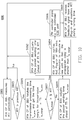
- FIG. 5 is a schematic diagram of a method of resource allocation implemented in the wireless communication system of FIG. 3 , in accordance with an exemplary embodiment of the present disclosure.
- step S510 at least one RRH 110 is registered to the SD-RRH controller 142.
- the SD-RRH controller 142 allocates the RRH resource by receiving an RRH profile of at least one RRH 110 in the RRH pool 11 from the at least one RRH 110, and generating the RRH allocation information accordingly.
- RRH profile may include an RRH ID, a link setup requirement, an RRH location, and an RRH MAC address.
- RRH profile may also include a BBU location assigned by the at least one of the RRH 110.
- the OSS 122a allocates the BBU resources to at least one BBU 121a through the EMS 123a. Specifically, the OSS 122a allocates the BBU resource by receiving a BBU profile of at least one BBU 121a in the BBU pool 12a from the at least one BBU 121a.
- the OSS 122a generates the BBU allocation information accordingly in response to the BBU profile, and transmits the BBU allocation information to the RRH infrastructure orchestrator 141.
- the BBU profile may include a BBU ID, and a BBU location.
- the BBU allocation information may include the BBU ID, a link setup requirement, and the BBU location.
- the link setup requirement includes a radio access technology.
- the link setup requirement includes bandwidth information.
- the link setup requirement includes band information.
- the link setup requirement includes multi-input multi-output information.
- the link setup requirement includes compression information.
- the link setup requirement includes a communication protocol.
- BBU allocation information includes an RRH location assigned by the OSS 122a or the BBU 121a.
- step S540 is performed after the BBU 121a received a BBU resource allocation request from the RRH infrastructure orchestrator 141 (not shown).
- the RRH infrastructure orchestrator 141 receives BBU information from the BBU 121a through the EMS 123a and the OSS 122a.
- the RRH infrastructure orchestrator 141 stores the BBU information.
- the BBU information includes BBU compression information.
- the BBU information includes BBU address information.
- step S550 the RRH infrastructure orchestrator 141 transmits the RRH resource allocation request to the SD-RRH controller 142.
- the RRH resource allocation request is generated in response to the BBU allocation information.
- the resource allocation request includes the link setup requirement.
- the SD-RRH controller 142 After the RRH resource allocation request is received by the SD-RRH controller 142, in step S560, the SD-RRH controller 142 generates and transmits the RRH allocation information to the RRH infrastructure orchestrator 141.
- the RRH allocation information includes a virtual RRH ID.
- the RRH allocation information includes a virtual RRH flowID.
- the RRH allocation information includes a virtual MAC address.
- the RRH infrastructure orchestrator 141 generates RRH configuration information in response to the RRH allocation information, and transmits the RRH configuration information to the SD-RRH controller 142.
- the RRH configuration information includes the virtual RRH ID.
- the RRH configuration information includes the virtual RRH flowID. In some embodiments, the RRH configuration information includes a BBU MAC address. In one embodiment, the BBU MAC address is stored in the RRH infrastructure orchestrator 141. In another embodiment, the BBU MAC address is obtained from the received BBU address information in the step 540.
- the RRH infrastructure orchestrator 141 transmits the FH resource allocation request to the FH controller 131.
- the FH resource allocation request is generated in response to the BBU allocation information received from the OSS 122a.
- the FH resource allocation request includes bandwidth information.
- the FH resource allocation request includes latency information.
- the FH resource allocation request includes jitter information.
- the FH resource allocation request includes the BBU MAC address.
- the FH resource allocation request includes the RRH MAC address.
- step S590 the FH controller 131 generates FH allocation information and transmits the FH allocation information to the RRH infrastructure orchestrator 141.
- step S600 the RRH infrastructure orchestrator 141 assigns and transmits a RoE parameter to the BBU 121a of the BBU pool 12a.
- the step S600 is performed after the step S560, when the RoE parameter includes RRH allocation information. In some other embodiments, the step S600 is performed after the step S590, when the RoE parameter includes FH allocation information.
- the data path including at least one RRH 110, the FH network 13 and BBU 121a is established by the RRH infrastructure orchestrator 141, in response to the RRH allocation information, the FH allocation information and the BBU allocation information.
- FIG. 6 is a schematic diagram of a Radio over Ethernet (RoE) control mechanism for the radio access network of FIG. 3 , in accordance with an exemplary embodiment of the present disclosure.
- the SD-RRH Controller 142 is configured to allocate RRH resources in response to the RRH resource allocation request from the RRH infrastructure orchestrator 141.
- the SD-RRH Controller 142 is further configured to allocate BBU resource in response to the BBU resource allocation request from the RRH infrastructure orchestrator 141 via an out-of-band data path, before the RRHs 110 starts to communicate with the BBU via an in-band data path during a running-time.
- a BBU MAC address is then assigned, by the RRH infrastructure orchestrator 141, to the allocated RRH.
- a flowID and the RRH MAC address are assigned to the BBU by the RRH infrastructure orchestrator 141.
- FIG. 7 is a schematic diagram of a header of a RoE common packet, in accordance with an exemplary embodiment of the present disclosure.
- the RoE common packet carries radio IQ data between BBU and RRH over an Ethernet transmission.
- a header 30 of a RoE common packet includes RoE parameters, such as supported versions (ver), packet type (pktType), flowID 31, length field (length), and ordering information (orderingInfo).
- the flowID 31 in the header of the RoE common packet
- a Peer MAC Address are mandatory parameters for RoE configuration for in-band control plane.
- the flowID 31 is used for multiplexing flows between source address and destination address (SA/DA) pair.
- the flowID 31 is assigned by the RRH controller via the out-of-band data path.
- the length field (length) may contain a value for the number of bytes in the payload (payload bytes) of the packet.
- the ordering information (orderingInfo) includes a sequence number.
- the RoE parameters include types of encryption. In some embodiments, the RoE parameters include bandwidth of the in-band data path. In some other embodiments, the RoE parameters includes compression algorithm of the in-band data path. In other embodiments, the RoE parameters include sample length of the in-band data path. In yet other embodiments, the RoE parameters include the number of samples per packet.
- FIG. 8 is a block diagram of an infrastructure of the Remote Radio Head orchestrator of FIG. 3 , in accordance with an exemplary embodiment of the present disclosure.
- the RRH infrastructure orchestrator 141 is configured for coordinating FH network resources, RRH resource and BBU resources to create an End-to-End link between RRH and BBU.
- the RRH infrastructure orchestrator 141 includes a communication protocol selecting module 70, a RAN resources mapping module 72, an RRH resources managing plug-in module 74, an FH resources managing plug-in module 76 and a BBU resources managing plug-in module 78.
- the communication protocol selecting module 70 is configured to receive a resource allocation instruction from a user equipment (e.g., request for processing upper layer application 80) and generate a RoE parameter accordingly.
- the RAN resources mapping module 72 is configured to provide APIs to manipulate RRH resource, FH network resource and BBU resource, and request RRH resource, FH network resource, and BBU resource in response to parameters from the communication protocol selecting module 70.
- the RAN resources mapping module 72 is further configured to generate and manage the topology between RRH and BBU resources.
- the RRH resources managing module 74 is configured to generate the RRH resource allocation request, and provide interface to SD-RRH controller 142 and the RAN resources mapping module 72.
- the FH resources managing module 76 is configured to generate the FH resource allocation request and provide interface to different FH controllers 131 for multi-layer/ multi-domain, and provide a common interface to the RAN resources mapping module 72.
- the BBU resources managing module 78 is configured to generate the BBU resource allocation request, and provide interface to OSS 122a and the RAN resources mapping module 72.
- the communication protocol selecting module 70 further includes an RRH infrastructure northbound interface 702, at least two communication protocol modules (e.g. a RoE plug-in module 704, a common public radio interface (CPRI) plug-in module 706, and a function-split plug-in module 708).
- the RRH infrastructure northbound interface 702 is configured to provide a common restful API for upper layer application 80 to create an End-to-End link for mobile RAN.
- the at least two communication protocol modules are configured to convert the request received from the user equipment (e.g., request for processing upper layer application 80) to specific parameters for the RAN resources mapping module 72.
- the RRH infrastructure orchestrator 141 includes the communication protocol selecting module 70 which allows the orchestrator 141 to coordinate the resource allocation between RRH pool 11, the FH network 13, and BBU pool 12 with at least two communication protocols.
- the two communication protocols are RoE protocol and CPRI protocol.
- FIG. 9 is a block diagram of an infrastructure of BBU of FIG. 1 , in accordance with an exemplary embodiment of the present disclosure.
- the BBU 121 includes a radio transport agent control plane (RTA CP) 50.
- the RTA CP 50 includes an RF emulation interface 51, a RoE packetizing module 53, a fast packet processing (FPP) module 55, a synchronization module 57 and a RoE control plane 59.
- the RF emulation interface 51 is configured to provide a communication interface which is independent of upper layer protocols.
- the RoE packetizing module 53 is configured to process IQ data encapsulation and de-capsulation.
- the fast packet processing module 55 is configured to enhance packet forwarding capability and adjust the timing of RoE packet to be transmitted.
- the fast packet processing module 55 includes Intel Data Plane Development Kit (DPDK).
- the synchronization module 57 is configured to provide transmission time interval (TTI) indicator to FPP module 55 and upper layer protocol, such us LTE upper layer protocol of LTE (LTE Protocol Stack 90).
- TTI transmission time interval
- the RoE control plane 59 is configured to perform a RoE out-of-band control plane between RRHs and BBUs.
- the RoE control plane 59 applies configurations (e.g., RRH MAC address and flowID) to the RoE packetizing module 53.
- the RoE control plane 59 exchanges RoE parameters with the RRH infrastructure orchestrator 141.
- the RoE parameters include BBU MAC addresses.
- the RoE parameters include compression algorithm.
- the RoE parameters include bandwidth of the in-band data path.
- the RoE parameters include the supported versions of RoE.
- the RoE control plane 59 retrieves operating information including BBU IDs.
- the operating information include a transmission processing time from upper layers (e.g. LTE Protocol Stack 90).
- FIG. 10 is a flowchart of a method of a dynamic compensation mechanism of propagation delay of the RAN of FIG. 3 , in accordance with an exemplary embodiment of the present disclosure.
- the example method 800 is provided by way of example only, as there are a variety of ways to carry out the method.
- the method 800 in some embodiments, is implemented with the configurations shown in FIG. 1 , FIG. 3 and FIG. 9 .
- Each block shown in FIG. 10 represents one or more processes, methods or subroutines.
- the order of blocks is illustrative only and the order of the blocks can change in response to the present disclosure. Additional steps can be added or fewer steps may be utilized, without departing from this disclosure.
- BBUs and RRHs are time synchronized.
- the transmission processing time delay and reception processing time delay in FH network are symmetric.
- a radio transport agent control plane e.g., RTA CP 50 in FIG. 9
- the RTA CP determines whether the measured RTT is greater than a previous measured RTT.
- step S805 is then performed.
- the RTA CP fetches a transmission processing time T tx_proc from the PHY layer. Therefore, a time margin T tx-margin for transmission is obtained via the following formula.
- T tx _ margin TTI ⁇ T tx _ proc .
- the TTI represents the transmission time interval between the BBU and the RRH.
- step S807 the RTA CP determines whether the T tx_margin is greater than a predetermined value, such as half of the measured RTT (1/2 RTT). When the T tx_margin is greater than 1/2 RTT, step S802 is then performed. In step S802, a packet sending time is adjusted to 1/2 RTT ahead of TTI by the RTA CP. When the T tx_margin is less than or equal to 1/2 RTT, step S809 is then performed.
- a predetermined value such as half of the measured RTT (1/2 RTT).
- step S809 the packet sending time is adjusted to T tx_margin ahead of TTI by the RTA CP, and step 804 is then performed.
- the RTA CP of the BBU notifies a RoE plug-in module (e.g. 704 in FIG. 8 ) of RRH infrastructure orchestrator to allocate a new data path so that a propagation delay of the new data path is less than T tx_margin .
- step S806 the FH controller configures a new optimized end-to-end path, and the propagation delay of the new optimized end-to-end path is less than T tx_margin .
- the RTA CP of the BBU receives a feedback signal from the RoE plug-in module of RRH infrastructure orchestrator, and monitors RTT during running time in response to the feedback signal.
- the feedback signal includes network compensation information. Therefore, in the present exemplary embodiment, a packet is sent, by BBU, ahead of each arrival of Transmission Time Interval (TTI) in order to compensate propagation delay caused by the FH network. Moreover, the propagation delay of the FH network is reduced due to a new path with shorter propagation delay being chosen.
- TTI Transmission Time Interval
- An orchestrator is coupled to an FH network, an RRH pool, and a BBU pool, and the orchestrator is configured to establish a data path in response to RRH allocation information, FH allocation information and BBU allocation information. Therefore, the orchestrator may coordinate FH network resources, RRH resource and BBU resources at the same time so that the consuming time of a link setup may be reduced. Moreover, the orchestrator may establish a data path without bounding the RRH resources to specific MNO.
- the orchestrator may assign a new data path in response to the updated RRH allocation information when a new RRH is registered, or in response to the updated FH allocation information, or in response to the updated BBU allocation information, so that the flexibility of the control plane of the wireless communication is enhanced.
- different communication protocols may be supported in the present disclosure, and the link setup may be dynamically adjusted accordingly.
Landscapes
- Engineering & Computer Science (AREA)
- Computer Networks & Wireless Communication (AREA)
- Signal Processing (AREA)
- Quality & Reliability (AREA)
- Mobile Radio Communication Systems (AREA)
Claims (29)
- Procédé d'allocation de ressources mis en œuvre dans un système de communication sans fil (100), comprenant :la réception, par un orchestrateur (141) d'un équipement électronique (14) dans le système de communication sans fil (100), d'au moins une instruction d'allocation de ressources (Sin) ;la génération, par l'orchestrateur (141), d'une demande d'allocation de ressources (SBBU) d'unité de bande de base, BBU, en réponse à l'au moins une instruction d'allocation de ressources (Sin) ;la transmission, par l'orchestrateur (141), de la demande d'allocation de ressources BBU (SBBU) à un pool BBU (12) ;la génération, par l'orchestrateur (141), d'une demande d'allocation de ressources de tête radio à distance, RRH (SRRH) et d'une demande d'allocation de ressources de liaison fronthaul, FH (SFH) en réponse à au moins une instruction d'allocation de ressources (Sin) ;la transmission, par l'orchestrateur (141), de la demande d'allocation de ressources RRH (SRRH) à un pool RRH (11), et de la demande d'allocation de ressources FH (SFH) à un réseau FH (13) ;la réception, par l'orchestrateur (141), d'informations d'allocation RRH (IRRH) d'une ressource RRH allouée depuis un contrôleur RRH (112) du pool RRH (11) ;la réception, par l'orchestrateur (141), d'informations d'allocation FH (IFH) d'une ressource de réseau FH allouée depuis un contrôleur FH (131) du réseau FH (13) ;la réception, par l'orchestrateur (141), d'informations d'allocation BBU (IBBU) d'une ressource BBU allouée depuis un contrôleur BBU (124) du pool BBU (12) ;l'établissement, par l'orchestrateur (141), d'un chemin de données comportant au moins une RRH (110) dans le pool RRH (11), le réseau FH (13) et au moins une BBU (121) dans le pool BBU (12), en réponse aux informations d'allocation RRH (IRRH), aux informations d'allocation FH (IFH) et aux informations d'allocation BBU (IBBU) ;dans lequel le procédé est caractérisé par :la réception, par l'orchestrateur (141), d'une demande d'établissement de chemin depuis le contrôleur BBU (124), dans lequel la demande d'établissement de chemin comprend une marge temporelle, Ttx-margin, pour la transmission ;la génération, par l'orchestrateur (141), d'une demande de compensation d'allocation de ressources FH en réponse à la demande d'établissement de chemin, dans lequel la demande de compensation d'allocation de ressources FH comprend la Ttx-margin ;la transmission, par l'orchestrateur (141), de la demande de compensation d'allocation de ressources FH au contrôleur FH (131) ;la réception, par l'orchestrateur (141), d'informations de compensation d'allocation FH générées par le contrôleur FH (131) en réponse à la demande de compensation d'allocation de ressources FH, dans lequel les informations de compensation d'allocation FH comprennent une nouvelle configuration de chemin de données où un délai de propagation de la nouvelle configuration du chemin de données est inférieur à la Ttx-margin ; etla transmission, par l'orchestrateur (141), des informations de compensation d'allocation FH au contrôleur BBU (124).
- Procédé selon la revendication 1, comprenant en outre :l'allocation, par le contrôleur RRH (112), d'une ressource RRH en réponse à la demande d'allocation de ressources RRH (SRRH), et la transmission des informations d'allocation RRH (IRRH) de la ressource RRH allouée à l'orchestrateur (141) ;l'allocation, par le contrôleur FH (131), d'une ressource de réseau FH en réponse à la demande d'allocation de ressources FH (SFH), et la transmission des informations d'allocation FH (IFH) de la ressource de réseau FH allouée à l'orchestrateur (141) ; etl'allocation, par le contrôleur BBU (124), d'une ressource BBU en réponse à la demande d'allocation de ressources BBU (SBBU), et la transmission des informations d'allocation BBU (IBBU) de la ressource BBU allouée à l'orchestrateur (141).
- Procédé selon la revendication 2, dans lequel l'étape d'allocation de la ressource BBU comporte en outre la réception, par le contrôleur BBU (124), d'un profil BBU de l'une des BBU (121) dans le pool BBU (12), dans lequel les informations d'allocation BBU (IBBU) sont générées en réponse au profil BBU.
- Procédé selon la revendication 2, dans lequel la demande d'allocation de ressources RRH (SRRH) est générée en réponse aux informations d'allocation BBU (IBBU) reçues depuis le contrôleur BBU (124), et les informations d'allocation BBU (IBBU) comportent une exigence d'établissement de liaison.
- Procédé selon la revendication 4, dans lequel les informations d'allocation BBU (IBBU) comportent en outre un emplacement BBU et un emplacement RRH.
- Procédé selon la revendication 2, dans lequel l'étape d'allocation de la ressource RRH comporte en outre la réception, par le contrôleur RRH (112), d'un profil RRH d'une RRH (110) dans le pool RRH (11), dans lequel les informations d'allocation RRH (IRRH) sont générées en réponse au profil RRH et à la demande d'allocation de ressources RRH (SRRH).
- Procédé selon la revendication 1, comportant en outre la transmission, par l'orchestrateur (141), d'informations de configuration RRH au contrôleur RRH (112), dans lequel les informations de configuration RRH sont générées, par l'orchestrateur (141), en réponse aux informations d'allocation RRH (IRRH).
- Procédé selon la revendication 1, comportant en outre la transmission, par l'orchestrateur (141), des informations d'allocation RRH (IRRH) au contrôleur BBU (121).
- Procédé selon la revendication 1, comportant en outre la réception, par l'orchestrateur (141), d'informations de compression BBU et d'informations d'adresse BBU depuis le contrôleur BBU (124).
- Procédé selon la revendication 1, comportant en outre la transmission, par l'orchestrateur (141), des informations d'allocation FH au contrôleur BBU (124).
- Équipement électronique (14) d'un système de communication sans fil (100), comprenant :
un orchestrateur (141) couplé respectivement à un réseau de liaison fronthaul, FH (13), un pool de tête radio à distance, RRH (11), et un pool d'unité de bande de base, BBU (12), dans lequel l'orchestrateur (141) est configuré pour :recevoir au moins une instruction d'allocation de ressources (Sin) ;générer une demande d'allocation de ressources d'unité de bande de base, BBU (SBBU) en réponse à l'au moins une instruction d'allocation de ressources (Sin) ;transmettre la demande d'allocation de ressources BBU (SBBU) à un pool BBU (12) ;générer une demande d'allocation de ressources de tête radio à distance, RRH (SRRH), et une demande d'allocation de ressources de liaison fronthaul, FH (SFH) en réponse à l'au moins une instruction d'allocation de ressources (Sin) ;transmettre la demande d'allocation de ressources RRH (SRRH) à un pool RRH (11), et la demande d'allocation de ressources FH (SFH) à un réseau FH (13) ;recevoir des informations d'allocation RRH (IRRH) d'une ressource RRH allouée depuis un contrôleur RRH (112) du pool RRH (11) ;recevoir des informations d'allocation FH (IFH) d'une ressource de réseau FH allouée depuis un contrôleur FH (131) du réseau FH (13) ;recevoir des informations d'allocation BBU (IBBU) d'une ressource BBU allouée depuis un contrôleur BBU (124) du pool BBU (12) ;établir un chemin de données en réponse aux informations d'allocation RRH (IRRH), aux informations d'allocation FH (IFH) et aux informations d'allocation BBU (IBBU), dans lequel le chemin de données comporte au moins une RRH (110) dans le pool RRH (11), le réseau FH (13) et au moins une BBU (121) dans le pool BBU (12) ;et l'orchestrateur est caractérisé en ce qu'il est configuré pour :recevoir une demande d'établissement de chemin depuis le contrôleur BBU (124), dans lequel la demande d'établissement de chemin comprend une marge temporelle, Ttx-margin pour la transmission ;générer une demande de compensation d'allocation de ressources FH en réponse à la demande d'établissement de chemin, dans lequel la demande de compensation d'allocation de ressources FH comprend la Ttx-margin ;transmettre la demande de compensation d'allocation de ressources FH au contrôleur FH (131) ; recevoir des informations de compensation d'allocation FH générées par le contrôleur FH (131) en réponse à la demande de compensation d'allocation de ressources FH, dans lequel les informations de compensation d'allocation FH comprennent une nouvelle configuration de chemin de données où un délai de propagation est inférieur à la Ttx-margin ; et pourtransmettre les informations de compensation d'allocation FH au contrôleur BBU (124). - Équipement électronique (14) selon la revendication 11, dans lequel les informations d'allocation RRH (IRRH) sont générées, par un contrôleur RRH (112) du pool RRH (11), en réponse à une ressource RRH allouée, les informations d'allocation FH (IFH) sont générées, par un contrôleur FH (131) du réseau FH (13), en réponse à une ressource de réseau FH allouée, et les informations d'allocation BBU (IBBU) sont générées, par un contrôleur BBU (124) du pool BBU (12), en réponse à une ressource BBU allouée.
- Équipement électronique (14) selon la revendication 11, dans lequel la demande d'allocation de ressources RRH (SRRH) est générée en réponse aux informations d'allocation BBU (IBBU) reçues depuis un contrôleur BBU (121), dans lequel les informations d'allocation BBU (IBBU) comprennent une exigence d'établissement de liaison.
- Équipement électronique (14) selon la revendication 13, dans lequel les informations d'allocation BBU (IBBU) comportent un emplacement BBU et un emplacement RRH.
- Équipement électronique (14) selon la revendication 11, dans lequel l'orchestrateur (141) est en outre configuré pour transmettre des informations de configuration RRH à un contrôleur RRH (112), dans lequel les informations de configuration RRH sont générées par l'orchestrateur (141) en réponse aux informations d'allocation RRH (IRRH).
- Équipement électronique (14) selon la revendication 11, dans lequel l'orchestrateur (141) est en outre configuré pour transmettre les informations d'allocation RRH (IRRH) à un contrôleur BBU (121).
- Équipement électronique (14) selon la revendication 11, dans lequel l'orchestrateur (141) est en outre configuré pour recevoir des informations de compression BBU et des informations d'adresse BBU depuis un contrôleur BBU (121).
- Équipement électronique (14) selon la revendication 11, dans lequel l'orchestrateur (141) est configuré pour transmettre les informations d'allocation FH (IFH) à un contrôleur BBU (121).
- Équipement électronique (14) selon la revendication 11, dans lequel l'orchestrateur (141) comprend :une unité de sélection de protocole de communication (70) configurée pour recevoir l'au moins une instruction d'allocation de ressources (Sin) et générer un paramètre Radio sur Ethernet, RoE, en réponse à l'au moins une instruction d'allocation de ressources (Sin) ;une unité de mappage de ressources de réseau d'accès radio, RAN (72) configurée pour générer un paramètre BBU, un paramètre RRH et un paramètre FH en réponse au paramètre RoE ;une unité enfichable de gestionnaire de ressources BBU (78) configurée pour générer la demande d'allocation de ressources BBU (SBBU) en réponse au paramètre BBU, et transmettre la demande d'allocation de ressources BBU (SBBU) à un contrôleur BBU (124) ;une unité enfichable de gestionnaire de ressources RRH (74) configurée pour générer la demande d'allocation de ressources RRH (SRRH) en réponse au paramètre RRH, et transmettre la demande d'allocation de ressources RRH (SRRH) à un contrôleur RRH (112) ; etune unité enfichable de gestionnaire de ressources FH (76) configurée pour générer la demande d'allocation de ressources FH (SFH) en réponse au paramètre FH, et transmettre la demande d'allocation de ressources FH (SFH) à un contrôleur FH (131).
- Équipement électronique (14) selon la revendication 11,
dans lequel le contrôleur RRH (112) est configuré pour recevoir un profil RRH depuis l'un des RRH (110), recevoir une demande d'allocation de ressources RRH (SRRH) depuis l'orchestrateur (141), générer les informations d'allocation RRH (IRRH) en réponse au profil RRH et à la demande d'allocation de ressources RRH (SRRH), et transmettre les informations d'allocation RRH (IRRH) à l'orchestrateur (141). - Système d'allocation de ressources d'unité de bande de base, BBU, comprenant :un contrôleur BBU (124) ; etune pluralité de BBU (121) couplées au contrôleur BBU (124) ;dans lequel le contrôleur BBU (124) est configuré pour :recevoir une demande d'allocation de ressources BBU (SBBU) depuis un orchestrateur (141) d'un équipement électronique (14), dans lequel l'orchestrateur (141) est respectivement couplé à un réseau fronthaul, FH (13) et à un pool de tête radio à distance, RRH (11) ;allouer une ressource BBU en réponse à la demande d'allocation de ressources BBU (SBBU) ; et pourtransmettre des informations d'allocation BBU (IBBU) à l'équipement électronique (14) en réponse à la ressource BBU allouée ;dans lequel chacune des BBU (121) comprend un agent de transport (50) configuré pour :ajuster, en réponse à un temps de traitement de transmission de la BBU (121) et à un temps d'aller-retour entre la BBU (121) et la RRH (110), un temps d'envoi de paquets ;et caractérisé en ce qu'il est configuré pour :transmettre une demande d'établissement de chemin à l'orchestrateur (141) par l'intermédiaire du contrôleur BBU (124), dans lequel la demande d'établissement de chemin comprend une marge temporelle, Ttx-margin, pour la transmission ; et pourrecevoir des informations de compensation d'allocation FH depuis l'orchestrateur (141) par l'intermédiaire du contrôleur BBU (124), dans lequel les informations de compensation d'allocation FH sont générées par un contrôleur FH (131) couplé à l'orchestrateur (141), dans lequel les informations de compensation d'allocation FH comprennent une nouvelle configuration de chemin de données où un délai de propagation de la nouvelle configuration de chemin de données est inférieur à la Ttx-margin.
- Système d'allocation de ressources BBU selon la revendication 21, dans lequel le contrôleur BBU (124) est en outre configuré pour :
recevoir un profil BBU depuis la BBU (121), dans lequel les informations d'allocation BBU (IBBU) sont générées en réponse au profil BBU. - Système d'allocation de ressources BBU selon la revendication 22, dans lequel les informations d'allocation BBU (IBBU) comprennent une exigence d'établissement de liaison.
- Système d'allocation de ressources BBU selon la revendication 23, dans lequel les informations d'allocation BBU (IBBU) comprennent en outre un emplacement BBU et un emplacement RRH.
- Système d'allocation de ressources BBU selon la revendication 21, dans lequel le contrôleur BBU (124) est en outre configuré pour :recevoir des informations d'allocation RRH (IRRH) depuis l'orchestrateur (141), dans lequel les informations d'allocation RRH (IRRH) sont générées par un contrôleur RRH (112) d'un pool RRH (11) ; et pourtransmettre les informations d'allocation RRH (IRRH) à au moins une BBU (121).
- Système d'allocation de ressources BBU selon la revendication 21, dans lequel le contrôleur BBU (124) est en outre configuré pour :recevoir des informations de compression BBU et des informations d'adresse BBU depuis au moins une BBU (121) ; et pourtransmettre les informations de compression BBU et les informations d'adresse BBU à l'équipement électronique (14).
- Système d'allocation de ressources BBU selon la revendication 21, dans lequel le contrôleur BBU (124) est en outre configuré pour recevoir des informations d'allocation FH (IFH) depuis l'orchestrateur (141), et les informations d'allocation FH (IFH) sont générées par un contrôleur FH (131) couplé à l'équipement électronique (14).
- Système d'allocation de ressources BBU selon la revendication 21, dans lequel l'agent de transport (50) comprend :une interface de communication (51) ;un dispositif de mise en paquets (53) couplé à l'interface de communication (51) ;une unité de traitement de paquets (55) couplée au dispositif de mise en paquets (53), dans lequel l'unité de traitement de paquets (55) est configurée pour ajuster le temps d'envoi de paquets ;une unité de synchronisation (57) couplée à l'unité de traitement de paquets (55) ; etun plan de contrôle (59) configuré pour configurer le dispositif de mise en paquets (53).
- Système d'allocation de ressources BBU selon la revendication 21, dans lequel le contrôleur BBU (124) comporte :un dispositif de système de support d'opération, OSS (122a, 122b) ; etun dispositif de système de gestion des éléments, EMS (123a, 123b) couplé entre le dispositif OSS (122a, 122b) et les BBU (121a, 121b).
Applications Claiming Priority (1)
| Application Number | Priority Date | Filing Date | Title |
|---|---|---|---|
| US201662382359P | 2016-09-01 | 2016-09-01 |
Publications (2)
| Publication Number | Publication Date |
|---|---|
| EP3291601A1 EP3291601A1 (fr) | 2018-03-07 |
| EP3291601B1 true EP3291601B1 (fr) | 2020-04-15 |
Family
ID=59772484
Family Applications (1)
| Application Number | Title | Priority Date | Filing Date |
|---|---|---|---|
| EP17189126.0A Active EP3291601B1 (fr) | 2016-09-01 | 2017-09-01 | Procédé d'allocation de ressources d'un système de communication sans fil et son mécanisme |
Country Status (4)
| Country | Link |
|---|---|
| US (1) | US9999057B2 (fr) |
| EP (1) | EP3291601B1 (fr) |
| CN (1) | CN107801249B (fr) |
| TW (1) | TWI660610B (fr) |
Families Citing this family (20)
| Publication number | Priority date | Publication date | Assignee | Title |
|---|---|---|---|---|
| EP3269118B8 (fr) | 2015-03-11 | 2021-03-17 | CommScope, Inc. of North Carolina | Réseau d'accès radio distribué comprenant une liaison de raccordement aux sites cellulaires adaptative |
| US10608734B2 (en) | 2015-10-22 | 2020-03-31 | Phluido, Inc. | Virtualization and orchestration of a radio access network |
| CN107087306A (zh) * | 2016-02-12 | 2017-08-22 | 台扬科技股份有限公司 | 用于无线信源调度的方法 |
| WO2018017468A1 (fr) | 2016-07-18 | 2018-01-25 | Phluido, Inc. | Synchronisation d'unités radio dans des réseaux d'accès radio |
| US20190114206A1 (en) * | 2017-10-18 | 2019-04-18 | Cisco Technology, Inc. | System and method for providing a performance based packet scheduler |
| US12016084B2 (en) | 2018-01-04 | 2024-06-18 | Commscope Technologies Llc | Management of a split physical layer in a radio area network |
| US11456833B2 (en) * | 2018-01-08 | 2022-09-27 | Samsung Electronics Co., Ltd. | Method for separating physical layer functions in wireless communication system |
| CN108882251B (zh) * | 2018-06-12 | 2019-08-30 | 京信通信系统(中国)有限公司 | 分布式Femto基站组网系统 |
| TWI669023B (zh) * | 2018-07-17 | 2019-08-11 | 明泰科技股份有限公司 | 雲端無線存取網路系統及其控制方法 |
| US10797734B2 (en) | 2018-08-01 | 2020-10-06 | Commscope Technologies Llc | System with multiple virtual radio units in a radio unit that is remote from at least one baseband controller |
| JPWO2020031710A1 (ja) * | 2018-08-10 | 2021-08-26 | ソニーグループ株式会社 | 無線通信装置および通信制御方法 |
| CN112913278B (zh) | 2018-10-25 | 2023-08-01 | 康普技术有限责任公司 | 用于集中式无线电接入网络的多载波无线电点 |
| WO2020119876A1 (fr) * | 2018-12-10 | 2020-06-18 | Telefonaktiebolaget Lm Ericsson (Publ) | Procédé et appareil pour attribution de ressources de réseau |
| KR102821713B1 (ko) * | 2019-02-12 | 2025-06-18 | 삼성전자 주식회사 | 통신 시스템에서의 효율적인 프론트홀을 이용한 신호 전송 방법 및 장치 |
| EP4169284A4 (fr) | 2020-06-18 | 2024-06-12 | John Mezzalingua Associates, LLC | Réseau radio intégré à capacité de liaison fronthaul multi-opérateurs et multi-formats de signal |
| KR20230031227A (ko) | 2020-06-30 | 2023-03-07 | 콤스코프 테크놀로지스, 엘엘씨 | 다수의 기능 분할, 다수의 무선 인터페이스 프로토콜, 다수의 세대의 무선 접속 기술 및 다수의 무선 주파수 대역을 지원하는 통합 원격 유닛을 갖는 개방형 무선 접속망 |
| CN114125020B (zh) * | 2020-09-11 | 2023-08-29 | 京东方科技集团股份有限公司 | 实时数据通信的方法、电子设备和系统 |
| FR3119060B1 (fr) * | 2021-01-20 | 2023-03-24 | Ebos Tech | Interface d’application dynamique basée sur une intention ascendante |
| US12034603B2 (en) * | 2022-03-04 | 2024-07-09 | AT&T Intellect al P Property I, L.P. | Pooling of baseband units in fifth generation networks and beyond |
| EP4566287A4 (fr) | 2022-08-04 | 2025-10-15 | Rakuten Symphony Inc | Configuration de porteuses et surveillance de dispositifs de communication dans un environnement de communication partagé |
Family Cites Families (13)
| Publication number | Priority date | Publication date | Assignee | Title |
|---|---|---|---|---|
| JP5614274B2 (ja) * | 2010-12-21 | 2014-10-29 | 富士通株式会社 | 無線通信システム |
| EP2512202B1 (fr) | 2011-04-12 | 2013-11-20 | Alcatel Lucent | Équilibre de charge dans un réseau d'accès radio |
| US9313827B2 (en) * | 2012-12-31 | 2016-04-12 | Broadcom Corporation | Radio over ethernet for radio access network and cloud-RAN |
| EP2959693B1 (fr) * | 2013-02-21 | 2017-11-22 | Altiostar Networks, Inc. | Systèmes et procédés pour coordonner la transmission de paquets de données par détection de type de trame dans une station de base |
| US9998200B2 (en) * | 2013-06-20 | 2018-06-12 | Aviat U.S., Inc. | Systems and methods for a fronthaul network |
| KR20160129893A (ko) * | 2014-03-05 | 2016-11-09 | 달리 시스템즈 씨오. 엘티디. | 원격 라디오 헤드를 포함하는 분산형 무선 시스템 |
| US9729215B2 (en) * | 2014-06-23 | 2017-08-08 | Samsung Electronics Co., Ltd. | OFDM signal compression |
| EP3202197B1 (fr) * | 2014-09-30 | 2020-12-16 | Viavi Solutions Inc. | Procédés et appareil pour auto-optimisation et/ou amélioration d'un réseau sans fil basé sur le cloud |
| US9762324B2 (en) * | 2014-10-31 | 2017-09-12 | Futurewei Technologies, Inc. | Channel mapping for an aggregated touchless wireless fronthaul |
| US10039097B2 (en) * | 2015-05-04 | 2018-07-31 | Verizon Patent And Licensing Inc. | Remote head simultaneously transmitting radio wave |
| US9876585B2 (en) * | 2015-07-03 | 2018-01-23 | Huawei Technologies Co., Ltd. | Method and system for partitioning signal processing chains in a communication network |
| US10015685B2 (en) * | 2015-12-04 | 2018-07-03 | Hon Hai Precision Industry Co., Ltd. | Network infrastructure and software defined remote radio head controller |
| US10582445B2 (en) * | 2016-03-01 | 2020-03-03 | Huawei Technologies Co., Ltd. | Method for dynamically slicing mobile devices |
-
2017
- 2017-08-28 US US15/687,616 patent/US9999057B2/en not_active Expired - Fee Related
- 2017-08-28 CN CN201710752373.8A patent/CN107801249B/zh not_active Expired - Fee Related
- 2017-08-28 TW TW106129171A patent/TWI660610B/zh not_active IP Right Cessation
- 2017-09-01 EP EP17189126.0A patent/EP3291601B1/fr active Active
Non-Patent Citations (1)
| Title |
|---|
| None * |
Also Published As
| Publication number | Publication date |
|---|---|
| US20180063847A1 (en) | 2018-03-01 |
| US9999057B2 (en) | 2018-06-12 |
| CN107801249A (zh) | 2018-03-13 |
| TWI660610B (zh) | 2019-05-21 |
| TW201813354A (zh) | 2018-04-01 |
| CN107801249B (zh) | 2020-02-25 |
| EP3291601A1 (fr) | 2018-03-07 |
Similar Documents
| Publication | Publication Date | Title |
|---|---|---|
| EP3291601A1 (fr) | Procédé d'allocation de ressources d'un système de communication sans fil et son mécanisme | |
| CN116405461B (zh) | 一种数据处理方法、网元设备以及可读存储介质 | |
| US11252742B2 (en) | Techniques for wireless access and wireline network integration | |
| US11895024B2 (en) | Method, device and computer readable medium for delivering data-plane packets by using separate transport service VNFC | |
| CN112165725B (zh) | 报文处理的方法及设备 | |
| US10992385B2 (en) | Apparatus and method for joint profile-based slicing of mobile access and optical backhaul | |
| US10390259B2 (en) | Data forwarding in a mobile communications network system with centralized gateway apparatus controlling distributed gateway elements | |
| JP2017505022A (ja) | バーチャル・レンジ・エクステンダを有するソフトウェア定義ネットワークインフラストラクチャ | |
| EP3487150B1 (fr) | Procédé et dispositif de traitement de paquets | |
| US9094871B2 (en) | Traffic management gateway for machine-to-machine network | |
| EP3629559B1 (fr) | Procédé de configuration d'une table de transfert pour un équipement utilisateur et appareil | |
| US20190014479A1 (en) | Communications network control | |
| US12483964B2 (en) | Multipath communication and control | |
| JP7617300B2 (ja) | 統合アクセス及びバックホールのための電力ヘッドルーム報告 | |
| KR101306305B1 (ko) | 이기종 네트워크 기반 데이터 동시 전송 서비스 방법 및 장치 | |
| CN105429844A (zh) | 网络系统、内网设备及内网设备的访问方法 | |
| US20250113254A1 (en) | Dynamically maximizing sub-channel bandwidth utilization for ofdma transmissions with artificial intelligence (ai) | |
| CN122029771A (zh) | 一种服务节点信息的确定方法和装置 | |
| HK40055384B (en) | Data processing method, network element device and readable storage medium | |
| KR101440187B1 (ko) | 네트워크 부하 밸런스 조절 장치 | |
| CN111866167A (zh) | 一种网络共享方法、装置、设备及计算机可读存储介质 | |
| CN120614589A (zh) | 固定无线接入部署的配置 | |
| KR20150069213A (ko) | 하이브리드 클라우드 환경의 통합관리를 위한 다채널 트래픽 분배방법 |
Legal Events
| Date | Code | Title | Description |
|---|---|---|---|
| PUAI | Public reference made under article 153(3) epc to a published international application that has entered the european phase |
Free format text: ORIGINAL CODE: 0009012 |
|
| STAA | Information on the status of an ep patent application or granted ep patent |
Free format text: STATUS: THE APPLICATION HAS BEEN PUBLISHED |
|
| AK | Designated contracting states |
Kind code of ref document: A1 Designated state(s): AL AT BE BG CH CY CZ DE DK EE ES FI FR GB GR HR HU IE IS IT LI LT LU LV MC MK MT NL NO PL PT RO RS SE SI SK SM TR |
|
| AX | Request for extension of the european patent |
Extension state: BA ME |
|
| STAA | Information on the status of an ep patent application or granted ep patent |
Free format text: STATUS: REQUEST FOR EXAMINATION WAS MADE |
|
| 17P | Request for examination filed |
Effective date: 20180906 |
|
| RBV | Designated contracting states (corrected) |
Designated state(s): AL AT BE BG CH CY CZ DE DK EE ES FI FR GB GR HR HU IE IS IT LI LT LU LV MC MK MT NL NO PL PT RO RS SE SI SK SM TR |
|
| STAA | Information on the status of an ep patent application or granted ep patent |
Free format text: STATUS: EXAMINATION IS IN PROGRESS |
|
| 17Q | First examination report despatched |
Effective date: 20190205 |
|
| GRAP | Despatch of communication of intention to grant a patent |
Free format text: ORIGINAL CODE: EPIDOSNIGR1 |
|
| STAA | Information on the status of an ep patent application or granted ep patent |
Free format text: STATUS: GRANT OF PATENT IS INTENDED |
|
| RIC1 | Information provided on ipc code assigned before grant |
Ipc: H04W 28/16 20090101AFI20200117BHEP Ipc: H04W 88/08 20090101ALN20200117BHEP |
|
| GRAS | Grant fee paid |
Free format text: ORIGINAL CODE: EPIDOSNIGR3 |
|
| INTG | Intention to grant announced |
Effective date: 20200204 |
|
| GRAA | (expected) grant |
Free format text: ORIGINAL CODE: 0009210 |
|
| STAA | Information on the status of an ep patent application or granted ep patent |
Free format text: STATUS: THE PATENT HAS BEEN GRANTED |
|
| AK | Designated contracting states |
Kind code of ref document: B1 Designated state(s): AL AT BE BG CH CY CZ DE DK EE ES FI FR GB GR HR HU IE IS IT LI LT LU LV MC MK MT NL NO PL PT RO RS SE SI SK SM TR |
|
| REG | Reference to a national code |
Ref country code: CH Ref legal event code: EP |
|
| REG | Reference to a national code |
Ref country code: DE Ref legal event code: R096 Ref document number: 602017014681 Country of ref document: DE |
|
| REG | Reference to a national code |
Ref country code: IE Ref legal event code: FG4D |
|
| REG | Reference to a national code |
Ref country code: AT Ref legal event code: REF Ref document number: 1258737 Country of ref document: AT Kind code of ref document: T Effective date: 20200515 |
|
| REG | Reference to a national code |
Ref country code: NL Ref legal event code: MP Effective date: 20200415 |
|
| REG | Reference to a national code |
Ref country code: LT Ref legal event code: MG4D |
|
| PG25 | Lapsed in a contracting state [announced via postgrant information from national office to epo] |
Ref country code: LT Free format text: LAPSE BECAUSE OF FAILURE TO SUBMIT A TRANSLATION OF THE DESCRIPTION OR TO PAY THE FEE WITHIN THE PRESCRIBED TIME-LIMIT Effective date: 20200415 Ref country code: FI Free format text: LAPSE BECAUSE OF FAILURE TO SUBMIT A TRANSLATION OF THE DESCRIPTION OR TO PAY THE FEE WITHIN THE PRESCRIBED TIME-LIMIT Effective date: 20200415 Ref country code: GR Free format text: LAPSE BECAUSE OF FAILURE TO SUBMIT A TRANSLATION OF THE DESCRIPTION OR TO PAY THE FEE WITHIN THE PRESCRIBED TIME-LIMIT Effective date: 20200716 Ref country code: NO Free format text: LAPSE BECAUSE OF FAILURE TO SUBMIT A TRANSLATION OF THE DESCRIPTION OR TO PAY THE FEE WITHIN THE PRESCRIBED TIME-LIMIT Effective date: 20200715 Ref country code: SE Free format text: LAPSE BECAUSE OF FAILURE TO SUBMIT A TRANSLATION OF THE DESCRIPTION OR TO PAY THE FEE WITHIN THE PRESCRIBED TIME-LIMIT Effective date: 20200415 Ref country code: IS Free format text: LAPSE BECAUSE OF FAILURE TO SUBMIT A TRANSLATION OF THE DESCRIPTION OR TO PAY THE FEE WITHIN THE PRESCRIBED TIME-LIMIT Effective date: 20200815 Ref country code: PT Free format text: LAPSE BECAUSE OF FAILURE TO SUBMIT A TRANSLATION OF THE DESCRIPTION OR TO PAY THE FEE WITHIN THE PRESCRIBED TIME-LIMIT Effective date: 20200817 Ref country code: NL Free format text: LAPSE BECAUSE OF FAILURE TO SUBMIT A TRANSLATION OF THE DESCRIPTION OR TO PAY THE FEE WITHIN THE PRESCRIBED TIME-LIMIT Effective date: 20200415 |
|
| PGFP | Annual fee paid to national office [announced via postgrant information from national office to epo] |
Ref country code: DE Payment date: 20200819 Year of fee payment: 4 Ref country code: FR Payment date: 20200826 Year of fee payment: 4 |
|
| REG | Reference to a national code |
Ref country code: AT Ref legal event code: MK05 Ref document number: 1258737 Country of ref document: AT Kind code of ref document: T Effective date: 20200415 |
|
| PG25 | Lapsed in a contracting state [announced via postgrant information from national office to epo] |
Ref country code: LV Free format text: LAPSE BECAUSE OF FAILURE TO SUBMIT A TRANSLATION OF THE DESCRIPTION OR TO PAY THE FEE WITHIN THE PRESCRIBED TIME-LIMIT Effective date: 20200415 Ref country code: RS Free format text: LAPSE BECAUSE OF FAILURE TO SUBMIT A TRANSLATION OF THE DESCRIPTION OR TO PAY THE FEE WITHIN THE PRESCRIBED TIME-LIMIT Effective date: 20200415 Ref country code: HR Free format text: LAPSE BECAUSE OF FAILURE TO SUBMIT A TRANSLATION OF THE DESCRIPTION OR TO PAY THE FEE WITHIN THE PRESCRIBED TIME-LIMIT Effective date: 20200415 Ref country code: BG Free format text: LAPSE BECAUSE OF FAILURE TO SUBMIT A TRANSLATION OF THE DESCRIPTION OR TO PAY THE FEE WITHIN THE PRESCRIBED TIME-LIMIT Effective date: 20200715 |
|
| PG25 | Lapsed in a contracting state [announced via postgrant information from national office to epo] |
Ref country code: AL Free format text: LAPSE BECAUSE OF FAILURE TO SUBMIT A TRANSLATION OF THE DESCRIPTION OR TO PAY THE FEE WITHIN THE PRESCRIBED TIME-LIMIT Effective date: 20200415 |
|
| REG | Reference to a national code |
Ref country code: DE Ref legal event code: R097 Ref document number: 602017014681 Country of ref document: DE |
|
| PG25 | Lapsed in a contracting state [announced via postgrant information from national office to epo] |
Ref country code: CZ Free format text: LAPSE BECAUSE OF FAILURE TO SUBMIT A TRANSLATION OF THE DESCRIPTION OR TO PAY THE FEE WITHIN THE PRESCRIBED TIME-LIMIT Effective date: 20200415 Ref country code: IT Free format text: LAPSE BECAUSE OF FAILURE TO SUBMIT A TRANSLATION OF THE DESCRIPTION OR TO PAY THE FEE WITHIN THE PRESCRIBED TIME-LIMIT Effective date: 20200415 Ref country code: DK Free format text: LAPSE BECAUSE OF FAILURE TO SUBMIT A TRANSLATION OF THE DESCRIPTION OR TO PAY THE FEE WITHIN THE PRESCRIBED TIME-LIMIT Effective date: 20200415 Ref country code: AT Free format text: LAPSE BECAUSE OF FAILURE TO SUBMIT A TRANSLATION OF THE DESCRIPTION OR TO PAY THE FEE WITHIN THE PRESCRIBED TIME-LIMIT Effective date: 20200415 Ref country code: SM Free format text: LAPSE BECAUSE OF FAILURE TO SUBMIT A TRANSLATION OF THE DESCRIPTION OR TO PAY THE FEE WITHIN THE PRESCRIBED TIME-LIMIT Effective date: 20200415 Ref country code: EE Free format text: LAPSE BECAUSE OF FAILURE TO SUBMIT A TRANSLATION OF THE DESCRIPTION OR TO PAY THE FEE WITHIN THE PRESCRIBED TIME-LIMIT Effective date: 20200415 Ref country code: RO Free format text: LAPSE BECAUSE OF FAILURE TO SUBMIT A TRANSLATION OF THE DESCRIPTION OR TO PAY THE FEE WITHIN THE PRESCRIBED TIME-LIMIT Effective date: 20200415 Ref country code: ES Free format text: LAPSE BECAUSE OF FAILURE TO SUBMIT A TRANSLATION OF THE DESCRIPTION OR TO PAY THE FEE WITHIN THE PRESCRIBED TIME-LIMIT Effective date: 20200415 |
|
| PLBE | No opposition filed within time limit |
Free format text: ORIGINAL CODE: 0009261 |
|
| STAA | Information on the status of an ep patent application or granted ep patent |
Free format text: STATUS: NO OPPOSITION FILED WITHIN TIME LIMIT |
|
| PG25 | Lapsed in a contracting state [announced via postgrant information from national office to epo] |
Ref country code: SK Free format text: LAPSE BECAUSE OF FAILURE TO SUBMIT A TRANSLATION OF THE DESCRIPTION OR TO PAY THE FEE WITHIN THE PRESCRIBED TIME-LIMIT Effective date: 20200415 Ref country code: PL Free format text: LAPSE BECAUSE OF FAILURE TO SUBMIT A TRANSLATION OF THE DESCRIPTION OR TO PAY THE FEE WITHIN THE PRESCRIBED TIME-LIMIT Effective date: 20200415 |
|
| 26N | No opposition filed |
Effective date: 20210118 |
|
| REG | Reference to a national code |
Ref country code: CH Ref legal event code: PL |
|
| PG25 | Lapsed in a contracting state [announced via postgrant information from national office to epo] |
Ref country code: SI Free format text: LAPSE BECAUSE OF FAILURE TO SUBMIT A TRANSLATION OF THE DESCRIPTION OR TO PAY THE FEE WITHIN THE PRESCRIBED TIME-LIMIT Effective date: 20200415 |
|
| REG | Reference to a national code |
Ref country code: BE Ref legal event code: MM Effective date: 20200930 |
|
| PG25 | Lapsed in a contracting state [announced via postgrant information from national office to epo] |
Ref country code: LU Free format text: LAPSE BECAUSE OF NON-PAYMENT OF DUE FEES Effective date: 20200901 |
|
| PG25 | Lapsed in a contracting state [announced via postgrant information from national office to epo] |
Ref country code: IE Free format text: LAPSE BECAUSE OF NON-PAYMENT OF DUE FEES Effective date: 20200901 Ref country code: LI Free format text: LAPSE BECAUSE OF NON-PAYMENT OF DUE FEES Effective date: 20200930 Ref country code: BE Free format text: LAPSE BECAUSE OF NON-PAYMENT OF DUE FEES Effective date: 20200930 Ref country code: CH Free format text: LAPSE BECAUSE OF NON-PAYMENT OF DUE FEES Effective date: 20200930 |
|
| PGFP | Annual fee paid to national office [announced via postgrant information from national office to epo] |
Ref country code: GB Payment date: 20210825 Year of fee payment: 5 |
|
| REG | Reference to a national code |
Ref country code: DE Ref legal event code: R119 Ref document number: 602017014681 Country of ref document: DE |
|
| PG25 | Lapsed in a contracting state [announced via postgrant information from national office to epo] |
Ref country code: TR Free format text: LAPSE BECAUSE OF FAILURE TO SUBMIT A TRANSLATION OF THE DESCRIPTION OR TO PAY THE FEE WITHIN THE PRESCRIBED TIME-LIMIT Effective date: 20200415 Ref country code: MT Free format text: LAPSE BECAUSE OF FAILURE TO SUBMIT A TRANSLATION OF THE DESCRIPTION OR TO PAY THE FEE WITHIN THE PRESCRIBED TIME-LIMIT Effective date: 20200415 Ref country code: CY Free format text: LAPSE BECAUSE OF FAILURE TO SUBMIT A TRANSLATION OF THE DESCRIPTION OR TO PAY THE FEE WITHIN THE PRESCRIBED TIME-LIMIT Effective date: 20200415 |
|
| REG | Reference to a national code |
Ref country code: GB Ref legal event code: 732E Free format text: REGISTERED BETWEEN 20220513 AND 20220518 |
|
| PG25 | Lapsed in a contracting state [announced via postgrant information from national office to epo] |
Ref country code: MK Free format text: LAPSE BECAUSE OF FAILURE TO SUBMIT A TRANSLATION OF THE DESCRIPTION OR TO PAY THE FEE WITHIN THE PRESCRIBED TIME-LIMIT Effective date: 20200415 Ref country code: MC Free format text: LAPSE BECAUSE OF FAILURE TO SUBMIT A TRANSLATION OF THE DESCRIPTION OR TO PAY THE FEE WITHIN THE PRESCRIBED TIME-LIMIT Effective date: 20200415 |
|
| PG25 | Lapsed in a contracting state [announced via postgrant information from national office to epo] |
Ref country code: FR Free format text: LAPSE BECAUSE OF NON-PAYMENT OF DUE FEES Effective date: 20210930 Ref country code: DE Free format text: LAPSE BECAUSE OF NON-PAYMENT OF DUE FEES Effective date: 20220401 |
|
| GBPC | Gb: european patent ceased through non-payment of renewal fee |
Effective date: 20220901 |
|
| PG25 | Lapsed in a contracting state [announced via postgrant information from national office to epo] |
Ref country code: GB Free format text: LAPSE BECAUSE OF NON-PAYMENT OF DUE FEES Effective date: 20220901 |