EP3291879B1 - Appareil pour administrer un rayonnement électromagnétique thérapeutique non-ultraviolet pour un tube trachéal - Google Patents
Appareil pour administrer un rayonnement électromagnétique thérapeutique non-ultraviolet pour un tube trachéal Download PDFInfo
- Publication number
- EP3291879B1 EP3291879B1 EP16787249.8A EP16787249A EP3291879B1 EP 3291879 B1 EP3291879 B1 EP 3291879B1 EP 16787249 A EP16787249 A EP 16787249A EP 3291879 B1 EP3291879 B1 EP 3291879B1
- Authority
- EP
- European Patent Office
- Prior art keywords
- emr
- endotracheal tube
- assembly
- therapeutic
- conduction line
- Prior art date
- Legal status (The legal status is an assumption and is not a legal conclusion. Google has not performed a legal analysis and makes no representation as to the accuracy of the status listed.)
- Active
Links
Images


Classifications
-
- A—HUMAN NECESSITIES
- A61—MEDICAL OR VETERINARY SCIENCE; HYGIENE
- A61N—ELECTROTHERAPY; MAGNETOTHERAPY; RADIATION THERAPY; ULTRASOUND THERAPY
- A61N5/00—Radiation therapy
- A61N5/06—Radiation therapy using light
- A61N5/0601—Apparatus for use inside the body
- A61N5/0603—Apparatus for use inside the body for treatment of body cavities
-
- A—HUMAN NECESSITIES
- A61—MEDICAL OR VETERINARY SCIENCE; HYGIENE
- A61L—METHODS OR APPARATUS FOR STERILISING MATERIALS OR OBJECTS IN GENERAL; DISINFECTION, STERILISATION OR DEODORISATION OF AIR; CHEMICAL ASPECTS OF BANDAGES, DRESSINGS, ABSORBENT PADS OR SURGICAL ARTICLES; MATERIALS FOR BANDAGES, DRESSINGS, ABSORBENT PADS OR SURGICAL ARTICLES
- A61L2/00—Disinfection or sterilisation of materials or objects, in general; Accessories therefor
- A61L2/02—Disinfection or sterilisation of materials or objects, in general; Accessories therefor using physical processes
- A61L2/08—Radiation
-
- A—HUMAN NECESSITIES
- A61—MEDICAL OR VETERINARY SCIENCE; HYGIENE
- A61M—DEVICES FOR INTRODUCING MEDIA INTO, OR ONTO, THE BODY; DEVICES FOR TRANSDUCING BODY MEDIA OR FOR TAKING MEDIA FROM THE BODY; DEVICES FOR PRODUCING OR ENDING SLEEP OR STUPOR
- A61M16/00—Devices for influencing the respiratory system of patients by gas treatment, e.g. ventilators; Tracheal tubes
- A61M16/04—Tracheal tubes
- A61M16/0434—Cuffs
-
- A—HUMAN NECESSITIES
- A61—MEDICAL OR VETERINARY SCIENCE; HYGIENE
- A61M—DEVICES FOR INTRODUCING MEDIA INTO, OR ONTO, THE BODY; DEVICES FOR TRANSDUCING BODY MEDIA OR FOR TAKING MEDIA FROM THE BODY; DEVICES FOR PRODUCING OR ENDING SLEEP OR STUPOR
- A61M16/00—Devices for influencing the respiratory system of patients by gas treatment, e.g. ventilators; Tracheal tubes
- A61M16/04—Tracheal tubes
- A61M16/0486—Multi-lumen tracheal tubes
-
- A—HUMAN NECESSITIES
- A61—MEDICAL OR VETERINARY SCIENCE; HYGIENE
- A61M—DEVICES FOR INTRODUCING MEDIA INTO, OR ONTO, THE BODY; DEVICES FOR TRANSDUCING BODY MEDIA OR FOR TAKING MEDIA FROM THE BODY; DEVICES FOR PRODUCING OR ENDING SLEEP OR STUPOR
- A61M16/00—Devices for influencing the respiratory system of patients by gas treatment, e.g. ventilators; Tracheal tubes
- A61M16/08—Bellows; Connecting tubes ; Water traps; Patient circuits
- A61M16/0816—Joints or connectors
-
- A—HUMAN NECESSITIES
- A61—MEDICAL OR VETERINARY SCIENCE; HYGIENE
- A61N—ELECTROTHERAPY; MAGNETOTHERAPY; RADIATION THERAPY; ULTRASOUND THERAPY
- A61N5/00—Radiation therapy
- A61N5/06—Radiation therapy using light
- A61N5/067—Radiation therapy using light using laser light
-
- A—HUMAN NECESSITIES
- A61—MEDICAL OR VETERINARY SCIENCE; HYGIENE
- A61L—METHODS OR APPARATUS FOR STERILISING MATERIALS OR OBJECTS IN GENERAL; DISINFECTION, STERILISATION OR DEODORISATION OF AIR; CHEMICAL ASPECTS OF BANDAGES, DRESSINGS, ABSORBENT PADS OR SURGICAL ARTICLES; MATERIALS FOR BANDAGES, DRESSINGS, ABSORBENT PADS OR SURGICAL ARTICLES
- A61L2/00—Disinfection or sterilisation of materials or objects, in general; Accessories therefor
- A61L2/02—Disinfection or sterilisation of materials or objects, in general; Accessories therefor using physical processes
- A61L2/08—Radiation
- A61L2/084—Visible light
-
- A—HUMAN NECESSITIES
- A61—MEDICAL OR VETERINARY SCIENCE; HYGIENE
- A61L—METHODS OR APPARATUS FOR STERILISING MATERIALS OR OBJECTS IN GENERAL; DISINFECTION, STERILISATION OR DEODORISATION OF AIR; CHEMICAL ASPECTS OF BANDAGES, DRESSINGS, ABSORBENT PADS OR SURGICAL ARTICLES; MATERIALS FOR BANDAGES, DRESSINGS, ABSORBENT PADS OR SURGICAL ARTICLES
- A61L2/00—Disinfection or sterilisation of materials or objects, in general; Accessories therefor
- A61L2/02—Disinfection or sterilisation of materials or objects, in general; Accessories therefor using physical processes
- A61L2/08—Radiation
- A61L2/085—Infrared radiation
-
- A—HUMAN NECESSITIES
- A61—MEDICAL OR VETERINARY SCIENCE; HYGIENE
- A61L—METHODS OR APPARATUS FOR STERILISING MATERIALS OR OBJECTS IN GENERAL; DISINFECTION, STERILISATION OR DEODORISATION OF AIR; CHEMICAL ASPECTS OF BANDAGES, DRESSINGS, ABSORBENT PADS OR SURGICAL ARTICLES; MATERIALS FOR BANDAGES, DRESSINGS, ABSORBENT PADS OR SURGICAL ARTICLES
- A61L2103/00—Materials or objects being the target of disinfection or sterilisation
- A61L2103/05—Living organisms or biological materials
-
- A—HUMAN NECESSITIES
- A61—MEDICAL OR VETERINARY SCIENCE; HYGIENE
- A61M—DEVICES FOR INTRODUCING MEDIA INTO, OR ONTO, THE BODY; DEVICES FOR TRANSDUCING BODY MEDIA OR FOR TAKING MEDIA FROM THE BODY; DEVICES FOR PRODUCING OR ENDING SLEEP OR STUPOR
- A61M16/00—Devices for influencing the respiratory system of patients by gas treatment, e.g. ventilators; Tracheal tubes
- A61M16/08—Bellows; Connecting tubes ; Water traps; Patient circuits
- A61M16/0816—Joints or connectors
- A61M16/0833—T- or Y-type connectors, e.g. Y-piece
-
- A—HUMAN NECESSITIES
- A61—MEDICAL OR VETERINARY SCIENCE; HYGIENE
- A61M—DEVICES FOR INTRODUCING MEDIA INTO, OR ONTO, THE BODY; DEVICES FOR TRANSDUCING BODY MEDIA OR FOR TAKING MEDIA FROM THE BODY; DEVICES FOR PRODUCING OR ENDING SLEEP OR STUPOR
- A61M2205/00—General characteristics of the apparatus
- A61M2205/05—General characteristics of the apparatus combined with other kinds of therapy
- A61M2205/051—General characteristics of the apparatus combined with other kinds of therapy with radiation therapy
-
- A—HUMAN NECESSITIES
- A61—MEDICAL OR VETERINARY SCIENCE; HYGIENE
- A61M—DEVICES FOR INTRODUCING MEDIA INTO, OR ONTO, THE BODY; DEVICES FOR TRANSDUCING BODY MEDIA OR FOR TAKING MEDIA FROM THE BODY; DEVICES FOR PRODUCING OR ENDING SLEEP OR STUPOR
- A61M2209/00—Ancillary equipment
- A61M2209/10—Equipment for cleaning
-
- A—HUMAN NECESSITIES
- A61—MEDICAL OR VETERINARY SCIENCE; HYGIENE
- A61N—ELECTROTHERAPY; MAGNETOTHERAPY; RADIATION THERAPY; ULTRASOUND THERAPY
- A61N5/00—Radiation therapy
- A61N5/06—Radiation therapy using light
- A61N5/0601—Apparatus for use inside the body
- A61N5/0603—Apparatus for use inside the body for treatment of body cavities
- A61N2005/0604—Lungs and/or airways
-
- A—HUMAN NECESSITIES
- A61—MEDICAL OR VETERINARY SCIENCE; HYGIENE
- A61N—ELECTROTHERAPY; MAGNETOTHERAPY; RADIATION THERAPY; ULTRASOUND THERAPY
- A61N5/00—Radiation therapy
- A61N5/06—Radiation therapy using light
- A61N2005/063—Radiation therapy using light comprising light transmitting means, e.g. optical fibres
-
- A—HUMAN NECESSITIES
- A61—MEDICAL OR VETERINARY SCIENCE; HYGIENE
- A61N—ELECTROTHERAPY; MAGNETOTHERAPY; RADIATION THERAPY; ULTRASOUND THERAPY
- A61N5/00—Radiation therapy
- A61N5/06—Radiation therapy using light
- A61N2005/065—Light sources therefor
- A61N2005/0651—Diodes
-
- A—HUMAN NECESSITIES
- A61—MEDICAL OR VETERINARY SCIENCE; HYGIENE
- A61N—ELECTROTHERAPY; MAGNETOTHERAPY; RADIATION THERAPY; ULTRASOUND THERAPY
- A61N5/00—Radiation therapy
- A61N5/06—Radiation therapy using light
- A61N2005/0658—Radiation therapy using light characterised by the wavelength of light used
- A61N2005/0659—Radiation therapy using light characterised by the wavelength of light used infrared
-
- A—HUMAN NECESSITIES
- A61—MEDICAL OR VETERINARY SCIENCE; HYGIENE
- A61N—ELECTROTHERAPY; MAGNETOTHERAPY; RADIATION THERAPY; ULTRASOUND THERAPY
- A61N5/00—Radiation therapy
- A61N5/06—Radiation therapy using light
- A61N2005/0658—Radiation therapy using light characterised by the wavelength of light used
- A61N2005/0662—Visible light
- A61N2005/0663—Coloured light
Definitions
- the present disclosure relates to a method and apparatus to provide therapeutic doses of non-ultraviolet light and/or sterilizing doses of non-ultraviolet light to stimulate healthy cell growth causing a healing effect and/or to inactivate infectious agents residing on, within, or generally around an endotracheal tube while said endotracheal tube is residing within a body cavity.
- Endotracheal tubes are medical devices used to provide mechanical ventilation for incapacitated patients. Unfortunately, they commonly cause hospital-acquired pneumonia (HAP). These devices cause infections in 91,000-126,000 patients every year and are the leading cause of death among hospital-acquired infections ( Scheld WM. Developments in the pathogenesis, diagnosis and treatment of nosocomial pneumonia. Surg Gynecol Obstet 1991; 172 Suppl:42 ).
- VAP ventilator-associated pneumonia
- Endotracheal tubes are known that function only to secure the airway and provide ventilation for the intubated patient.
- Various hydrophobic, antibiotic, and/or anti-inflammatory coatings for endotracheal tubes are also known. Examples of these coatings include antibiotic agents like chlorhexidine or silver. This coating is intended to inhibit bacterial and fungal colonization of the device.
- these proposals are only marginally effective in-vivo and are unable to prevent numerous infections and deaths.
- UV light ultraviolet light
- UV light is well known to cause damage to living cells ( Rittie. "UV-light-induced signal cascades and skin aging.” Ageing research reviews 1.4 (2002): 705-720 ).
- WO2013/049491 provides a process and device for directly medicinally treating interior tissue during or after intubation of a patient by passing medicinal radiant energy transversely through the intubation device to irradiate the internal patient tissue for promoting healing or for an antimicrobial effect.
- the present disclosure comprises a method and apparatus for delivering therapeutic doses in-vivo to stimulate healthy cell growth causing a healing effect and/or to inactivating infectious agents on or within an endotracheal tube.
- the exemplary embodiments of this disclosure allow for therapeutic treatments that stimulate healthy cell growth enhancing healing and/or that inactivate infectious agents while the endotracheal tube is residing within a patient's body cavity.
- this disclosure relates to an endotracheal tube assembly that incorporates the delivery of electromagnetic radiation (EMR) therapy in addition to the functions of existing standard of care endotracheal tubes (securing airway, providing a passage for mechanical ventilation, etc.).
- EMR electromagnetic radiation
- the endotracheal tube assembly includes an endotracheal tube with an associated EMR source that provides non-ultraviolet, therapeutic EMR of sufficient fluency to inactivate one or more infectious agents and/or to stimulate healthy cell growth causing a healing effect.
- terapéutica should be understood to mean of or relating to the treatment of disease, including infectious agents, as well as serving or performed to maintain health, including enhancing healthy cell growth.
- the exemplary embodiments of this disclosure include retrofitting a EMR delivery system to an existing standard endotracheal tube where the EMR delivery system is permanently attached to the endotracheal tube or where the EMR delivery system is removably insertable into the endotracheal tube, as well as including the use of a custom-made endotracheal tube that incorporates the EMR delivery system into the structure of the endotracheal tube.
- a quick-connect coupling may be used and/or the insertable portion of the EMR delivery system may move freely and axially relative to the endotracheal tube.
- This disclosure also provides methods and apparatuses for effectively sterilizing the body surface for the area in, on, or around the endotracheal tube. This is done through use of EMR at sufficient intensities capable of inactivation of infectious agents.
- This source can be from a single or group of EMR sources including, but not limited to, a light emitting diode, a semiconductor laser, a diode laser, an incandescent and fluorescent light source.
- This EMR source provides non-ultraviolet, sterilizing EMR providing one or more wavelengths in the range of approximately 380 nm to approximately 900 nm.
- each EMR wavelength should be of a narrow spectrum and centered around one wavelength from the group, and has intensity sufficient to inactivate one or more infectious agents.
- This group includes several wavelengths centered about: 400 nm, 405 nm, 415 nm, 430 nm, 440 nm, 455 nm, 470 nm, 475 nm, 660 nm, and 808 nm.
- the intensity and power of the light emitted is particularly suitable for the inactivation of infectious agents, thus a range of fluency covering 0.1 J/cm 2 to 1 kJ/cm 2 and a range of powers from 0.005 mW to 1 W, and power density range covering 1 mW/cm 2 and 1 W/cm 2 are of interest for these device assemblies and methods.
- the EMR delivery system directs the EMR lengthwise along the wall of said flexible tube in the plane of the flexure thereof for emission of the EMR internal and/or external to the endotracheal tube body.
- EMR delivery system may be inserted such that its forward end terminates toward the forward end of the flexible, endotracheal tube body.
- the endotracheal tube assembly and method for disinfection could be utilized in an adjustable or predetermined duty cycle. If treatments began immediately after sterile procedure was initiated, device related infections may be inhibited. This includes device related biofilm growth.
- connection to refers to any form of interaction between two or more entities, including mechanical, electrical, magnetic, electromagnetic, fluid, and thermal interaction. Two components may be coupled to each other even though they are not in direct contact with each other.
- abutting refers to items that are in direct physical contact with each other, although the items may not necessarily be attached together.
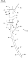
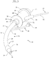
- an endotracheal tube assembly 10 is shown in a profile view.
- the endotracheal tube assembly 10 is capable of insertion into a patient's trachea to ventilate, to maintain patency of the patient's airway, and to deliver therapeutic electromagnetic radiation (EMR) to the patient.
- EMR electromagnetic radiation
- FIGS. 1 and 2 illustrate that the therapeutic endotracheal tube assembly 10 comprises an endotracheal tube 12 and an EMR delivery system 13 having a lumen 14 defined by a tube wall 16 and a ventilator collar 18.
- the endotracheal tube 12 has tube body 20 with an upper tube portion 21 having a proximate end 22 and a lower tube portion 23 having a forward end 24 for insertion into the patient's trachea.
- the proximate end 22 of the upper tube portion 21 of the tube body 20 is coupled to the ventilator collar 18 in any suitable manner.
- the endotracheal tube 12 typically has an inflatable cuff 26 surrounding the tube wall 16 proximate the forward end 24.
- the lumen 14 of the endotracheal tube 12 is used principally to pass ventilating gas from the ventilator (not shown) to the patient's lungs.
- the lumen 14 may be used as conduit for the passage of medical instruments of various kinds, including the EMR delivery system 13 of this disclosure.
- a secondary lumen (not shown in FIGS. 1 and 2 , but see FIG. 13 for examples of secondary lumens) may be used as a conduit for the insertable portions of the EMR delivery system 13.
- the endotracheal tube 12 has two separate side ports 28, a cuff inflation conduit 30 and an optical conduit 32.
- the cuff inflation conduit 30 has a cuff inflation fitting 34 through which an inflation fluid is injected to inflate the inflatable cuff 26 to seal the trachea or removed to deflate the inflatable cuff 26 so that the endotracheal tube 12 may be removed from the patient's trachea.
- the optical conduit 32 receives the EMR delivery system 13 as will be described more fully below.
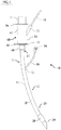
- the exemplary embodiment of FIG. 2 differs from the embodiment in FIG. 1 in that the endotracheal tube 12 has a single, combined side port 28 because the cuff inflation conduit 30 ports into the optical conduit 32.
- the exemplary embodiments of FIGS. 1 and 2 would most likely be custom made for optimum compatibility with the EMR delivery system 13. Nevertheless, if one of the side ports 28 in an off-the-self, multiple side port endotracheal tube 12 is suitably compatible with the EMR delivery system 13, then such an endotracheal tube 12 need not be custom made.
- the EMR delivery system 13 comprises an EMR source 36 for emitting non-ultraviolet, therapeutic EMR having intensity sufficient to activate desired therapeutic properties within the patient, an EMR conduction line 37 (shown in phantom lines) conducive to the propagation of EMR from the EMR source 36 along the endotracheal tube 12, and an EMR coupling 38 to connect the EMR source 36 to a coupling end 39 of the EMR conduction line 37.
- desired therapeutic properties within the patient may include stimulating healthy cell growth or sterilizing one or more target organisms or infectious agents.
- the EMR source 36 may comprise an optical element (not shown) such as light emitting diodes, lasers, filtered fluorescents, filtered incandescents, and any combination thereof.
- the EMR source 36 may provide non-ultraviolet, sterilizing EMR at one or more wavelengths in the range of approximately 380 nm to approximately 900 nm.
- each EMR wavelength should be of a narrow spectrum centered about a wavelength that has demonstrated sterilization when applied at an intensity sufficient to inactivate one or more infectious agents.
- the intensity and power of the light emitted is particularly suitable for the inactivation of infectious agents, thus a range of fluency covering 0.1 J/cm 2 to 1 kJ/cm 2 and a range of powers from 0.005 mW to 1 W, and power density range covering 1 mW/cm 2 and 1 W/cm 2 are of interest for these device assemblies and methods.
- Also of interest to this endotracheal tube assembly 10 is the use of use of different wavelengths between 532 and 1064 nm for stimulating tissue healing properties. Exemplary wavelengths have demonstrated desirable tissue healing properties, including those wavelengths centered about 633 nm, 808 nm, and 830 nm. Doses ranging from 0.09 to 90 J/cm 2 have been demonstrated to be effective, with the predominating values from 1 to 5 J/cm 2 . However, doses 150 J/cm 2 are of particular interest for the applications contemplated by this disclosure.
- the endotracheal tube assembly 10 and method for disinfection could be utilized in an adjustable or predetermined duty cycle. If treatments began immediately after sterile procedure was initiated, device related infections may be inhibited. This includes device related biofilm growth.
- a treatment may include at least one wavelength of therapeutic EMR that acts as a predominant wavelength selected to sterilize one or more target organisms and selected from the group of wavelengths centered about 400 nm, 405 nm, 415 nm, 430 nm, 440 nm, 455 nm, 470 nm, 475 nm, 660 nm, and 808 nm.
- Another treatment may include alternating the predominant wavelength between a first predominant wavelength and a second predominant wavelength (differing from the first predominant wavelength) in a selected treatment pattern. Further, sterilizing EMR and EMR that stimulates healthy cell growth may be transmitted simultaneously in tandem or alternatively.
- the EMR conduction line 37 has the coupling end 39 and a distal end 41 and may be insertable into the endotracheal tube 12 to deliver non-ultraviolet, therapeutic EMR within the patient at sufficient intensity to activate desired therapeutic properties.
- the EMR conduction line 37 may comprise one or more optical features such as a reflective surface, an optically transmissible material, a lens, a fiber optic filament, a gradient modification, light emitting portions, opaque portions, or any combination thereof.
- the EMR conduction line 37 may also comprise plastic, silica, or other polymeric optical fiber capable of transmission and dispersion of light over a given distance.
- the endotracheal tube 12 may be optically clear or translucent. These portions of clearness or translucency permit the EMR emitted from the EMR conduction line 37 to deliver therapeutic EMR to the inside of the tube wall 16 and to body tissue external to the tube wall 16 and proximate the clear or translucent portions.
- the endotracheal tube 12 will be an off-the-shelf (rather than custom made) item and the entire length of the endotracheal tube 12 will be clear or translucent.
- custom made endotracheal tubes 12 may have portions that are not clear or translucent so not to permit the emission of the EMR from the endotracheal tubes 12 at those opaque portions.
- the EMR conduction line 37 may comprise at least one optical feature selected from a group of optical features such as a reflective surface, an optically transmissible material, a lens, a fiber optic filament, and any combination thereof. It also may be capable of transmitting more than one wavelength or intensity EMR. Multiple wavelengths may be transmitted simultaneously, one after another or in tandem, or a combination thereof (for example, one constantly on and the other wavelength pulsed). Multiple intensities may be transmitted through the same element simultaneously. Alternating patterns of light treatments may also be transmitted.
- the optical conduit 32 may be incorporated onto, into, or through the endotracheal tube body 12 at optical joinder site 40 and the cuff inflation conduit 30 may be incorporated onto, into, or through the endotracheal tube body 20 at inflation joinder site 42, as shown in FIG. 1 .
- the single, combined side port 28 of FIG. 2 may be incorporated onto, into, or through the endotracheal tube body 12 at combined joinder site 44 and the cuff inflation conduit 30 may be incorporated onto, into, or through the optical conduit 32 at a combining site 46. Together, the cuff inflation conduit 30 and the optical conduit 32 form a combined conduit 48.
- the ventilator collar 18 depicted in FIGS 1-5 represents a typical ventilator collar 18 known in the art.
- the ventilator collar 18 could be modified to accommodate a suitable connection of the endotracheal tube 12 to a ventilator without departing from the spirit of the present disclosure.
- the ventilator collar 18 comprises a connection sleeve 49 that secures the endotracheal tube 12 to the ventilator collar 18, a stop flange 50 to arrest over-engagement, and an engagement cylinder 51.
- the ventilator may be coupled to the engagement cylinder 51 in either a snug male or female engagement.
- FIG. 3 illustrates another exemplary embodiment that differs from the two previously described.
- the endotracheal tube 12 has one or more embedded, partially embedded, or internally channeled EMR conduction lines 37 (not visible in FIG. 3 , but described in more detail regarding FIGS. 9-13 below) and a single side port 28 for the cuff inflating conduit 30.
- the EMR source 36 has an EMR directing ring 52 disposed within a cylindrical aperture 54.
- the ventilator collar 18 and the cylindrical aperture 54 share a centerline 56 when the cylindrical aperture aligns for engagement with the engagement cylinder 51 of the ventilator collar 18.
- the EMR directing ring 52 communicates with the one or more embedded, partially embedded, or internally channeled EMR conduction lines 37 enable the propagation of EMR down the endotracheal tube 12.
- the communication of EMR from the EMR directing ring 52 to the EMR conducting lines 37 may be accomplished in any of a number of ways known to those skilled in the art, such as by direct contact of exposed ends of the EMR conducting lines 37 to the EMR directing ring 52 or through one or more collimating lenses or reflective mirrors (not shown). This configuration allows the EMR source 36 to be effectively coupled to all or part of the engagement cylinder 51 so that therapeutic EMR may be delivered into a patient's body without interfering with the coupling to the ventilator.
- FIGS. 4 and 5 depict first an exploded view of an exemplary embodiment of a therapeutic endotracheal tube assembly 10 ( FIG. 4 ) and then an engaged view ( FIG. 5 ).
- FIG. 15 is a perspective view of the therapeutic endotracheal tube assembly 10 in an engaged configuration.
- an existing, off-the-shelf endotracheal tube 12 may be retrofitted with an endotracheal adapter 68 that converts the existing endotracheal tube 12 into a therapeutic endotracheal tube assembly 10 fully capable of delivering therapeutic EMR into a patient's body without interfering with the coupling to the ventilator.
- the endotracheal adapter 68 is disposed intermediate of the ventilator collar 18 and the ventilator.
- the endotracheal adapter 68 of FIGS 4-7 has an adapter body 69, an EMR port 70, a ventilator fitting end 71 corresponding in configuration to the engagement cylinder 51 of the ventilator collar 18, an engagement end 72 configured to engage the engagement cylinder 51 in male/female engagement, an adapter stop flange 74 for arresting over-engagement with the ventilator, and a ventilation channel 75 through which ventilation gas may travel without meaningful interference.
- the ventilation channel 75 of the port adapter 68 may accommodate passage of one or more of a diagnostic probe, a therapeutic tool, an additional energy source, an optical device, a surgical instrument, and a monitor into the endotracheal tube 12.
- the EMR port 70 may have either an optical conduit 32 (as shown) or may receive the EMR conduction line 37 directly so long as the port is adequately sealed so that the ventilation operation will not be compromised.
- the form of seal may be any suitable seal known by those in the art, such as a rubber diaphragm that may be penetrated by the EMR conduction line 37 or O-rings positioned within the EMR port 70, or the like.
- the endotracheal adapter 68 as retrofitted, enables the removable insertion of the EMR conduction line 37 to whatever depth within or through the tube body 20 is desired.
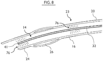
- the EMR conduction line 37 is shown in FIG. 8 as being fully inserted within the tube body 20 where EMR illumination 76 is shown, by way of example, at the distal end 41 of the EMR conduction line 37.
- therapeutic EMR may be delivered anywhere along the length of the tube body 20 provided the tube body 20 is clear or translucent at least at those portions of the tube body 20 where emitted therapeutic EMR is desired and the EMR conduction line 37 emits EMR of sufficient intensity directed (radially, obliquely, longitudinally, from the distal end, and any combination thereof) through the tube body 20 to the desired location(s).
- the methods and apparatus for providing gradient modification and/or multiple emission portions for the EMR conduction line 37 are described in co-pending application entitled METHODS AND APPARATUS TO INACTIVATE INFECTIOUS AGENTS ON A CATHETER RESIDING IN A BODY CAVITY, U.S. Application Serial No. 13/801,750, filed March 13, 2013 .
- FIG. 6 shows the EMR conduction line 37 disposed directly within the EMR port 70 so that the EMR conduction line 37 may be inserted unobstructed into the ventilation channel 75 and then into the lumen 14 of the tube body 20 of the endotracheal tube 12 and may be subsequently removed.
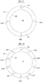
- FIGS. 9-13 of the present disclosure depicted are cross-sectional views of various exemplary configurations of the endotracheal tube body 20.
- the section taken is transverse to a longitudinal axis of the endotracheal tube body 20 at any point (other than at the balloon cuff 26) along the axis downstream of the most downstream joinder site 40, 42, 44.
- the cross-sectional views show a portion of the exemplary endotracheal tube bodies 20 sometimes identified herein as a distal endotracheal tube having a tube wall 16, bounded by an internal surface 60 and an external surface 62, encompassing the lumen 14, previously identified.
- FIG. 9 illustrates one such configuration, wherein one or more distal optical conduits 64A-C are embedded in the endotracheal tube wall 16 between the internal surface 60 and the external surface 62.
- This configuration occurs distal to the site where the external optical conduit 32 ports into the endotracheal tube body 20.
- An embedded cuff inflation conduit 58 is the downstream extension of the cuff inflation conduit 30 and is located along the wall 16 of the endotracheal tube body 20 between the inflation joinder site 42 and the inflatable cuff 26.
- FIG. 10 a cross-sectional view illustrating another such configuration shows multiple distal optical conduits 64A-I and the embedded cuff inflation conduit 58 embedded in the endotracheal tube wall 16.
- FIG. 11 another exemplary configuration is depicted as a variation of the orientations and size of the distal optical conduits 64A-D in the endotracheal tube wall 16.
- FIG. 12 a cross-sectional view illustrates another exemplary configuration, wherein one or more distal optical conduits 64A-F may be located along the internal surface 60 of the endotracheal tube wall 16. As shown, they may be partially embedded within the endotracheal tube wall 16.
- FIG. 13 a cross-sectional view illustrates yet another exemplary configuration, wherein one or more distal optical conduits 64A-D may be located along the internal surface 60 of the endotracheal tube wall 56. Differing from FIG. 9 , the distal optical conduits 64A-D are not embedded in the internal surface 60 of the endotracheal tube wall 16, but are associated with the internal surface 60, but may be enclosed within one or more optical conduit channels 66 that serve as secondary lumens to the main lumen 14.
- the EMR source 36 may also be incorporated into the ventilator itself, using the ventilator tubing as a conduit for passing the optical conduit 32 to the endotracheal tube body 20.
- the ventilator connection on the proximal end 22 of the endotracheal tube body 20 could then serve as a combined ventilator and optical conduit coupling apparatus. These connections could also be individual at the point of coupling with the endotracheal tube body 20.
- EMR is transmitted directly down the endotracheal tube wall 16 using the tube wall 16 as an optical conduit. This may be done in conjunction with any of the other EMR source 36 configurations specifically mentioned above or that would be understood by those skilled in the art armed with this disclosure.
- FIG. 14 is a profile, sectional view illustrating an exemplary embodiment of a port adapter 68 having a tripartite configuration for connection to an endotracheal tube 12, wherein the tripartite port adapter 68 accommodates the connection of various-sized ventilator connectors in either male or female engagement and also accommodates the insertion of an EMR conduction line 37 of an EMR delivery system 13 into the endotracheal tube 12.
- the tripartite port adapter 68 comprises ventilator collar 18, an EMR port 70, engagement end 72, and a secondary port 78.
- the ventilator collar 18, EMR port 70, engagement end 72, and secondary port 78 are angled from each other such that the multiple connections with ventilator, EMR delivery system 13, endotracheal tube 12, and any other type of device (a diagnostic probe, a therapeutic tool, an additional energy source, an optical device, a surgical instrument, a monitor, and the like) may be connected to the tripartite port adapter 68 without obstruction or interference.
- the ventilator collar 18 has a first inner diameter 80 and a first outer diameter 82 that differs from the second inner diameter 84 and second outer diameter 86 of the secondary port 78 of the tripartite port adapter 68 so that the tripartite port adapter 68 can accommodate connection to ventilators having different-sized connectors.
- any of the ventilator collar 18, EMR port 70, and secondary port 78 is not needed or is between uses, they may be capped so not to compromise ventilation of the patient.
- the tripartite port adapter 68 maybe retrofit between a ventilator and an endotracheal tube 12.
- a custom-made endotracheal tube 12 may be made by affixing the tripartite port adapter 68 (as the ventilator collar 18) directly to the tube body 20.
- any suitable coupling may be used, such as an adhesive, a pinch coupling, a male/female connection, or barbed inserted component, for example.
Landscapes
- Health & Medical Sciences (AREA)
- Pulmonology (AREA)
- Biomedical Technology (AREA)
- Engineering & Computer Science (AREA)
- General Health & Medical Sciences (AREA)
- Public Health (AREA)
- Veterinary Medicine (AREA)
- Animal Behavior & Ethology (AREA)
- Life Sciences & Earth Sciences (AREA)
- Hematology (AREA)
- Emergency Medicine (AREA)
- Anesthesiology (AREA)
- Heart & Thoracic Surgery (AREA)
- Pathology (AREA)
- Nuclear Medicine, Radiotherapy & Molecular Imaging (AREA)
- Radiology & Medical Imaging (AREA)
- Epidemiology (AREA)
- Physics & Mathematics (AREA)
- Optics & Photonics (AREA)
- Radiation-Therapy Devices (AREA)
Claims (13)
- Ensemble tube endotrachéal thérapeutique (10) à insérer dans la trachée d'un patient pour ventiler, pour maintenir la perméabilité des voies respiratoires du patient et pour administrer un rayonnement électromagnétique thérapeutique (REM) au patient, l'ensemble tube endotrachéal thérapeutique (10) comprenant :un tube endotrachéal (12) ayant :a) une lumière (14) définie par une paroi de tube (16), une partie de tube supérieure (21) ayant une extrémité proximale (22) et une partie de tube inférieure (23) ayant une extrémité avant (24) à insérer dans la trachée du patient, etb) un ballonnet gonflable (26) entourant la paroi de tube (16) à proximité de l'extrémité avant (24) ; etun système d'administration de REM (13) comprenant :a) une source REM (36) pour émettre un REM thérapeutique non ultraviolet ayant une intensité suffisante pour activer des propriétés thérapeutiques souhaitées chez le patient, la source REM (36) comprend en outre une plage de fluence couvrant 0,1 J/cm2 à 1 kJ/cm2, et une plage de puissances allant de 0,005 mW à 1 W, et une plage de densité de puissance couvrant 1 mW/cm2 à 1 W/cm2 ;b) une ligne de conduction REM (37) propice à la propagation de REM de la source REM (36) le long du tube endotrachéal (12), la ligne de conduction REM (37) ayant une extrémité de couplage (39) et une extrémité distale et pouvant être insérée dans le tube endotrachéal (12) pour administrer un REM thérapeutique non ultraviolet au patient à une intensité suffisante pour activer des propriétés thérapeutiques souhaitées ; etc) un dispositif de couplage (38) pour relier la source REM (36) à l'extrémité de couplage (39) de la ligne de conduction REM (37) ;caractérisé en ce que :le tube endotrachéal (12) comprend en outre un collier de ventilateur (18), la partie de tube supérieure (21) ayant une extrémité proximale (22) couplée à un collier de ventilateur (18) ; etl'ensemble tube endotrachéal thérapeutique (10) comprend en outre un adaptateur endotrachéal (68) disposé entre le collier de ventilateur (18) et le ventilateur, la ligne de conduction REM (37) est disposée directement à l'intérieur de l'orifice REM (70) de sorte que la ligne de conduction REM (37) puisse être insérée dans le canal de ventilation (75) puis dans la lumière (14) du corps de tube (20) du tube endotrachéal (12) et peut être ultérieurement retirée.
- Ensemble (10) selon la revendication 1, dans lequel au moins une partie du tube endotrachéal (12) est optiquement transparente et/ou translucide de sorte que le REM thérapeutique émette de la ligne de conduction REM de manière externe et/ou interne vers le tube endotrachéal (12).
- Ensemble (10) selon la revendication 1, dans lequel la source REM comprend un élément optique, l'élément optique étant choisi dans le groupe constitué de diodes électroluminescentes, de lasers, de matériaux fluorescents filtrés, de matériaux incandescents filtrés et de toute combinaison de ceux-ci.
- Ensemble (10) selon la revendication 1, dans lequel le tube endotrachéal (12) comprend en outre un élément de réception pour recevoir l'insertion de la ligne de conduction REM, l'élément de réception étant choisi dans le groupe constitué d'un conduit encastré qui est encastré dans la paroi de tube, d'une lumière interne secondaire, d'un canal partiellement encastré et d'un canal adjacent extérieur.
- Ensemble (10) selon la revendication 1, dans lequel le REM thérapeutique est administré à un cycle de fonctionnement prédéterminé.
- Ensemble (10) selon la revendication 1, dans lequel le REM thérapeutique a au moins une longueur d'onde, chaque longueur d'onde étant comprise dans la plage allant de 380 nm à 900 nm.
- Ensemble (10) selon la revendication 1,
dans lequel l'au moins une longueur d'onde de REM thérapeutique comprend
une longueur d'onde prédominante choisie pour stériliser au moins un organisme cible et choisie dans un groupe de longueurs d'onde constitué de longueurs d'onde centrées autour d'environ 400 nm, 405 nm, 415 nm, 430 nm, 440 nm, 455 nm , 470 nm, 475 nm, 660 nm et 808 nm. - Ensemble (10) selon la revendication 5, dans lequel la longueur d'onde prédominante alterne entre une première longueur d'onde prédominante et une deuxième longueur d'onde prédominante dans un modèle de traitement sélectionné.
- Ensemble (10) selon la revendication 1, dans lequel la ligne de conduction REM (37) est mobile axialement par rapport au tube endotrachéal (12).
- Ensemble (10) selon la revendication 1, dans lequel le collier de ventilateur (18) comprend une configuration tripartite ayant un premier collier, un deuxième collier et un conduit d'entrée, le premier collier ayant une première partie cylindrique ayant un premier diamètre intérieur et un premier diamètre extérieur qui diffère d'un deuxième diamètre intérieur et d'un deuxième diamètre extérieur d'une deuxième partie cylindrique du deuxième collier, le conduit d'entrée servant à recevoir le passage de la ligne de conduction REM dans le tube endotrachéal (12).
- Ensemble (10) selon la revendication 1, dans lequel la ligne de conduction REM (37) émet un REM depuis au moins une partie de la ligne de conduction REM (37), l'émission de REM depuis la ligne de conduction REM (37) appartenant au groupe d'émissions constitué d'émissions radiale, oblique, longitudinale, à partir de l'extrémité distale, et de toute combinaison de celles-ci.
- Ensemble (10) selon la revendication 10, dans lequel l'adaptateur endotrachéal (68) a une ouverture à travers laquelle au moins l'un d'une sonde de diagnostic, d'un outil thérapeutique, d'une source d'énergie supplémentaire, d'un dispositif optique, d'un instrument chirurgical et d'un moniteur passe dans le tube endotrachéal (12).
- Ensemble (10) selon la revendication 1, dans lequel l'adaptateur endotrachéal (68) peut être fixé de manière amovible au collier de ventilateur (18) de sorte que le système d'administration de REM ou le système de conduction de REM soit monté en rattrapage sur le tube endotrachéal (12).
Priority Applications (1)
| Application Number | Priority Date | Filing Date | Title |
|---|---|---|---|
| EP20187074.8A EP3760281B1 (fr) | 2015-04-30 | 2016-04-29 | Appareil pour administrer un rayonnement électromagnétique thérapeutique non-ultraviolet pour un tube trachéal |
Applications Claiming Priority (4)
| Application Number | Priority Date | Filing Date | Title |
|---|---|---|---|
| US201562154789P | 2015-04-30 | 2015-04-30 | |
| US201662292028P | 2016-02-05 | 2016-02-05 | |
| US15/141,511 US10870015B2 (en) | 2015-04-30 | 2016-04-28 | Methods and apparatus to deliver therapeutic non-ultraviolet electromagnetic radiation for an endotracheal tube |
| PCT/US2016/030187 WO2016176608A1 (fr) | 2015-04-30 | 2016-04-29 | Procédés et appareil pour administrer un rayonnement électromagnétique thérapeutique non-ultraviolet pour un tube trachéal |
Related Child Applications (1)
| Application Number | Title | Priority Date | Filing Date |
|---|---|---|---|
| EP20187074.8A Division EP3760281B1 (fr) | 2015-04-30 | 2016-04-29 | Appareil pour administrer un rayonnement électromagnétique thérapeutique non-ultraviolet pour un tube trachéal |
Publications (3)
| Publication Number | Publication Date |
|---|---|
| EP3291879A1 EP3291879A1 (fr) | 2018-03-14 |
| EP3291879A4 EP3291879A4 (fr) | 2019-01-16 |
| EP3291879B1 true EP3291879B1 (fr) | 2020-07-29 |
Family
ID=57199430
Family Applications (2)
| Application Number | Title | Priority Date | Filing Date |
|---|---|---|---|
| EP20187074.8A Active EP3760281B1 (fr) | 2015-04-30 | 2016-04-29 | Appareil pour administrer un rayonnement électromagnétique thérapeutique non-ultraviolet pour un tube trachéal |
| EP16787249.8A Active EP3291879B1 (fr) | 2015-04-30 | 2016-04-29 | Appareil pour administrer un rayonnement électromagnétique thérapeutique non-ultraviolet pour un tube trachéal |
Family Applications Before (1)
| Application Number | Title | Priority Date | Filing Date |
|---|---|---|---|
| EP20187074.8A Active EP3760281B1 (fr) | 2015-04-30 | 2016-04-29 | Appareil pour administrer un rayonnement électromagnétique thérapeutique non-ultraviolet pour un tube trachéal |
Country Status (4)
| Country | Link |
|---|---|
| US (2) | US10870015B2 (fr) |
| EP (2) | EP3760281B1 (fr) |
| CA (1) | CA2984445C (fr) |
| WO (1) | WO2016176608A1 (fr) |
Families Citing this family (31)
| Publication number | Priority date | Publication date | Assignee | Title |
|---|---|---|---|---|
| US11497932B2 (en) | 2012-04-05 | 2022-11-15 | Light Line Medical, Inc. | Electromagnetic radiation delivery and monitoring system and methods for preventing, reducing and/or eliminating catheter-related infections during institutional or in-home use |
| US11229808B2 (en) | 2012-04-05 | 2022-01-25 | Light Line Medical, Inc. | Methods and apparatus to deliver therapeutic, non-ultraviolet electromagnetic radiation versatilely via a catheter residing in a body cavity |
| US11229728B1 (en) | 2020-08-24 | 2022-01-25 | Light Line Medical, Inc. | Method and apparatus to deliver therapeutic, non-ultraviolet electromagnetic radiation in a dialysis system |
| CA2900038C (fr) * | 2013-02-07 | 2021-02-09 | Rocomp Global, Llc | Dispositifs, assemblages, systemes et procedes de ciblage par rayonnement electromagnetique |
| WO2014159874A1 (fr) | 2013-03-14 | 2014-10-02 | Teleflex Medical Incorporated | Système de thérapie par rayonnement ultraviolet antimicrobien basé sur une fibre optique |
| US10149957B2 (en) | 2013-10-03 | 2018-12-11 | University Of Utah Research Foundation | Tracheal intubation system including a laryngoscope |
| CA162808S (en) * | 2015-06-03 | 2016-01-07 | Smart Rs Inc | Adaptor for inhaled medication delivery |
| CN111701144B (zh) | 2015-07-28 | 2023-03-21 | 诺欧生物有限责任公司 | 用于对一氧化氮的光疗调节的系统和方法 |
| US12109429B2 (en) | 2015-07-28 | 2024-10-08 | Know Bio, Llc | Phototherapeutic light for treatment of pathogens |
| US10226642B2 (en) | 2015-11-06 | 2019-03-12 | Illuminoss Medical, Inc. | Systems and methods for anti-microbial effect for bones |
| CN111315434B (zh) * | 2017-08-03 | 2022-05-24 | 光线医疗股份有限公司 | 递送治疗性非紫外线电磁辐射以使感染物灭活的方法和装置 |
| US10765767B2 (en) * | 2018-06-19 | 2020-09-08 | Inikoa Medical, Inc. | Disinfecting methods and apparatus |
| DE102020109727A1 (de) * | 2019-04-25 | 2020-10-29 | Löwenstein Medical Technology S.A. | Beatmungsgerät |
| JP2023511112A (ja) * | 2020-01-20 | 2023-03-16 | ライト ライン メディカル,インコーポレイティド | 取外し可能カテーテル可視光線治療システムのための方法及び装置 |
| US20210283356A1 (en) * | 2020-03-16 | 2021-09-16 | Ghassan S Kassab | Application of uv/fir to treat infections in the respiratory tract |
| US12447354B2 (en) | 2020-03-19 | 2025-10-21 | Know Bio, Llc | Illumination devices for inducing biological effects |
| US11147984B2 (en) | 2020-03-19 | 2021-10-19 | Know Bio, Llc | Illumination devices for inducing biological effects |
| US12011611B2 (en) | 2020-03-19 | 2024-06-18 | Know Bio, Llc | Illumination devices for inducing biological effects |
| US11986666B2 (en) | 2020-03-19 | 2024-05-21 | Know Bio, Llc | Illumination devices for inducing biological effects |
| US20240016246A1 (en) * | 2020-03-25 | 2024-01-18 | Sharon A. Keene | Near field safe antimicrobial wavelength disinfection via optical fibers, light guides, or light pipes for percutaneous or indwelling ambulatory disinfection of catheters, vascular access lines, drains, endo-tracheal tubes and similar medical devices |
| USD1031024S1 (en) * | 2020-05-13 | 2024-06-11 | Tien-Sheng Chen | Endotracheal tube |
| CN115867341A (zh) * | 2020-05-18 | 2023-03-28 | 佩德罗·路易斯·布拉沃·加西亚 | 用于患者机械通气的气管内装置 |
| EP4117773A4 (fr) | 2020-05-18 | 2024-04-10 | Pathy Medical, LLC | Dispositifs et procédés d'application d'une lumière thérapeutique pour réduire le risque de contracter une maladie infectieuse pour du personnel soignant |
| US12347337B2 (en) | 2020-12-10 | 2025-07-01 | Know Bio, Llc | Enhanced testing and characterization techniques for phototherapeutic light treatments |
| US12115384B2 (en) | 2021-03-15 | 2024-10-15 | Know Bio, Llc | Devices and methods for illuminating tissue to induce biological effects |
| US11654294B2 (en) | 2021-03-15 | 2023-05-23 | Know Bio, Llc | Intranasal illumination devices |
| US11813368B2 (en) | 2021-08-27 | 2023-11-14 | Abl Medical Inc. | Anti-microbial blue light systems and methods |
| DE102021127885A1 (de) * | 2021-10-26 | 2023-04-27 | Technische Hochschule Ulm, Körperschaft des öffentlichen Rechts | Beatmungssystem |
| US20230218919A1 (en) * | 2022-01-10 | 2023-07-13 | The Research Foundation For The State University Of New York | Therapeutic lighted catheters |
| US12533014B2 (en) | 2022-11-13 | 2026-01-27 | Light Line Medical, Inc. | Disposable introducer for advancing an elongate member into a tubular structure |
| US12527945B2 (en) | 2022-11-13 | 2026-01-20 | Light Line Medical, Inc. | Disposable fiber optic introducer component of a light delivery system for preventing, reducing and/or eliminating infections during institutional or in-home use |
Family Cites Families (26)
| Publication number | Priority date | Publication date | Assignee | Title |
|---|---|---|---|---|
| US6196225B1 (en) | 1995-10-23 | 2001-03-06 | Dean O. Allgeyer | Endotracheal tube for use during fiberoptic assisted intubation and with other intubating stylets |
| US5913816A (en) | 1997-10-31 | 1999-06-22 | Imagyn Medical Technologies, Inc. | Intubation device and method |
| US8187278B2 (en) * | 1998-08-25 | 2012-05-29 | Advanced Photodynamic Technologies, Inc. | Photodynamic cellular and acellular organism eradication utilizing a photosensitive material and benzalkonium chloride |
| WO2003084601A2 (fr) | 2002-04-02 | 2003-10-16 | Lumerx, Inc. | Dispositifs et procedes utilisant la lumiere visible pour affaiblir et/ou tuer des micro-organismes dans le corps |
| US20070219604A1 (en) | 2006-03-20 | 2007-09-20 | Palomar Medical Technologies, Inc. | Treatment of tissue with radiant energy |
| US7473219B1 (en) * | 2003-03-07 | 2009-01-06 | Glenn Joshua P | Flexible fiber optic bronchoscope one-way valve |
| US7159590B2 (en) | 2004-12-20 | 2007-01-09 | Rife Robert W | Trachea tube with germicidal light source |
| US8041428B2 (en) | 2006-02-10 | 2011-10-18 | Electrocore Llc | Electrical stimulation treatment of hypotension |
| US20080058785A1 (en) * | 2006-04-12 | 2008-03-06 | Searete Llc, A Limited Liability Corporation Of The State Of Delaware | Autofluorescent imaging and target ablation |
| US8556950B2 (en) | 2006-08-24 | 2013-10-15 | Boston Scientific Scimed, Inc. | Sterilizable indwelling catheters |
| WO2010047672A1 (fr) | 2008-10-20 | 2010-04-29 | Rao Chamkurkishtiah P | Tube endotrachéal et de trachéostomie autonettoyant et stérilisant |
| US8468637B2 (en) * | 2009-02-06 | 2013-06-25 | Endoclear Llc | Mechanically-actuated endotracheal tube cleaning device |
| NL2002622C2 (nl) * | 2009-03-13 | 2010-09-16 | Ez Blocker B V | Bronchoscopisch verdeelstuk. |
| US8480722B2 (en) | 2009-03-20 | 2013-07-09 | Mark Klepper | Tubular device delivering light and radiation into a patient |
| US8574490B2 (en) | 2009-03-31 | 2013-11-05 | Bactriblue, Ltd. | Methods and apparatus for reducing count of infectious agents in intravenous access systems |
| US8457715B2 (en) | 2009-04-08 | 2013-06-04 | Covidien Lp | System and method for determining placement of a tracheal tube |
| US8779386B2 (en) | 2010-03-03 | 2014-07-15 | U-VIVO ApS | Assembly and method for disinfecting lumens of devices |
| CA2838005C (fr) * | 2011-04-29 | 2018-04-17 | Board Of Regents The University Of Texas System | Procedes et appareils pour un guidage et une confirmation optoacoustiques de la pose d'un appareil medical a demeure |
| US9259513B2 (en) * | 2011-06-20 | 2016-02-16 | Sri International | Photocatalytic disinfection of implanted catheters |
| US10357661B2 (en) * | 2011-09-30 | 2019-07-23 | Percuvision, Llc | Medical device and method for internal healing and antimicrobial purposes |
| US9808647B2 (en) * | 2012-04-05 | 2017-11-07 | Veritas Medical, L.L.C. | Methods and apparatus to inactivate infectious agents on a catheter residing in a body cavity |
| US20130323119A1 (en) | 2012-06-01 | 2013-12-05 | Carefusion 303, Inc. | System and method for disinfection of medical devices |
| US20150190649A1 (en) * | 2012-06-29 | 2015-07-09 | The General Hospital Corporation | Embedded photonic systems and methods for irradiation of medium with same |
| WO2014089028A1 (fr) | 2012-12-04 | 2014-06-12 | Endoclear Llc | Dispositifs, systèmes et procédés de nettoyage par aspiration |
| WO2015054102A1 (fr) | 2013-10-07 | 2015-04-16 | Endoclear Llc | Systèmes et procédés pour bloquer sélectivement un flux d'air respiratoire |
| US10016575B2 (en) | 2014-06-03 | 2018-07-10 | Endoclear Llc | Cleaning devices, systems and methods |
-
2016
- 2016-04-28 US US15/141,511 patent/US10870015B2/en active Active
- 2016-04-29 CA CA2984445A patent/CA2984445C/fr active Active
- 2016-04-29 WO PCT/US2016/030187 patent/WO2016176608A1/fr not_active Ceased
- 2016-04-29 EP EP20187074.8A patent/EP3760281B1/fr active Active
- 2016-04-29 EP EP16787249.8A patent/EP3291879B1/fr active Active
-
2020
- 2020-11-23 US US17/102,033 patent/US20210093885A1/en not_active Abandoned
Non-Patent Citations (1)
| Title |
|---|
| None * |
Also Published As
| Publication number | Publication date |
|---|---|
| US20160317832A1 (en) | 2016-11-03 |
| EP3760281B1 (fr) | 2023-11-29 |
| EP3760281A1 (fr) | 2021-01-06 |
| CA2984445A1 (fr) | 2016-11-03 |
| EP3291879A4 (fr) | 2019-01-16 |
| WO2016176608A1 (fr) | 2016-11-03 |
| CA2984445C (fr) | 2021-12-14 |
| US10870015B2 (en) | 2020-12-22 |
| US20210093885A1 (en) | 2021-04-01 |
| EP3291879A1 (fr) | 2018-03-14 |
Similar Documents
| Publication | Publication Date | Title |
|---|---|---|
| EP3291879B1 (fr) | Appareil pour administrer un rayonnement électromagnétique thérapeutique non-ultraviolet pour un tube trachéal | |
| US8933416B2 (en) | Catheter insertion sterilization | |
| US11229808B2 (en) | Methods and apparatus to deliver therapeutic, non-ultraviolet electromagnetic radiation versatilely via a catheter residing in a body cavity | |
| US10357661B2 (en) | Medical device and method for internal healing and antimicrobial purposes | |
| EP1284789B1 (fr) | Dispositif servant à empêcher des infections | |
| US10307612B2 (en) | Methods and apparatus to deliver therapeutic, non-ultraviolet electromagnetic radiation to inactivate infectious agents and/or to enhance healthy cell growth via a catheter residing in a body cavity | |
| EP3661579B1 (fr) | Appareil pour délivrer un rayonnement électromagnétique thérapeutique, non ultraviolet pour inactiver des agents infectieux | |
| US20080159908A1 (en) | Method and apparatus for sterilizing indwelling catheters | |
| US11554187B2 (en) | Remote pathogen eradication | |
| US20170182194A1 (en) | Apparatus and method of sterilizing lumens in medical instruments | |
| US20100222852A1 (en) | Apparatus and Method for Decolonizing Microbes on the Surfaces of the Skin and In Body Cavities | |
| US20060195165A1 (en) | Optical therapy devices, systems, kits and methods for providing therapy to a body cavity | |
| EP3411117B1 (fr) | Appareil pour système thérapeutique à lumière visible de cathéter amovible | |
| US10894173B2 (en) | Methods and apparatus to deliver therapeutic, non-ultraviolet electromagnetic radiation to inactivate infectious agents and/or to enhance healthy cell growth via a catheter residing in a body cavity | |
| CA3172543A1 (fr) | Therapie interne par ultraviolets | |
| CN102553084A (zh) | 一种光治疗装置 | |
| JP3254314U (ja) | 体腔の中に留置するカテーテルを介して可変的に治療用非紫外線電磁放射線を送達するための装置 | |
| CN117396235A (zh) | 用于对导管周围的皮肤组织消毒的系统 | |
| ES3056490T3 (en) | Breathing system | |
| ES2740992T3 (es) | Conjunto y método para desinfectar pasos interiores de dispositivos | |
| CN120900065A (zh) | 一种基于紫外线的人工气道囊上潴留物消杀装置 | |
| TW202135786A (zh) | 免疫苗式侵入性病毒感染後滅菌自療方法 |
Legal Events
| Date | Code | Title | Description |
|---|---|---|---|
| STAA | Information on the status of an ep patent application or granted ep patent |
Free format text: STATUS: THE INTERNATIONAL PUBLICATION HAS BEEN MADE |
|
| PUAI | Public reference made under article 153(3) epc to a published international application that has entered the european phase |
Free format text: ORIGINAL CODE: 0009012 |
|
| STAA | Information on the status of an ep patent application or granted ep patent |
Free format text: STATUS: REQUEST FOR EXAMINATION WAS MADE |
|
| 17P | Request for examination filed |
Effective date: 20171130 |
|
| AK | Designated contracting states |
Kind code of ref document: A1 Designated state(s): AL AT BE BG CH CY CZ DE DK EE ES FI FR GB GR HR HU IE IS IT LI LT LU LV MC MK MT NL NO PL PT RO RS SE SI SK SM TR |
|
| AX | Request for extension of the european patent |
Extension state: BA ME |
|
| DAV | Request for validation of the european patent (deleted) | ||
| DAX | Request for extension of the european patent (deleted) | ||
| RAP1 | Party data changed (applicant data changed or rights of an application transferred) |
Owner name: LIGHT LINE MEDICAL, INC. |
|
| A4 | Supplementary search report drawn up and despatched |
Effective date: 20181219 |
|
| RIC1 | Information provided on ipc code assigned before grant |
Ipc: A61N 1/36 20060101AFI20181213BHEP |
|
| GRAP | Despatch of communication of intention to grant a patent |
Free format text: ORIGINAL CODE: EPIDOSNIGR1 |
|
| STAA | Information on the status of an ep patent application or granted ep patent |
Free format text: STATUS: GRANT OF PATENT IS INTENDED |
|
| INTG | Intention to grant announced |
Effective date: 20200221 |
|
| GRAS | Grant fee paid |
Free format text: ORIGINAL CODE: EPIDOSNIGR3 |
|
| GRAA | (expected) grant |
Free format text: ORIGINAL CODE: 0009210 |
|
| STAA | Information on the status of an ep patent application or granted ep patent |
Free format text: STATUS: THE PATENT HAS BEEN GRANTED |
|
| AK | Designated contracting states |
Kind code of ref document: B1 Designated state(s): AL AT BE BG CH CY CZ DE DK EE ES FI FR GB GR HR HU IE IS IT LI LT LU LV MC MK MT NL NO PL PT RO RS SE SI SK SM TR |
|
| REG | Reference to a national code |
Ref country code: CH Ref legal event code: EP |
|
| REG | Reference to a national code |
Ref country code: AT Ref legal event code: REF Ref document number: 1295083 Country of ref document: AT Kind code of ref document: T Effective date: 20200815 |
|
| REG | Reference to a national code |
Ref country code: IE Ref legal event code: FG4D |
|
| REG | Reference to a national code |
Ref country code: DE Ref legal event code: R096 Ref document number: 602016040924 Country of ref document: DE |
|
| REG | Reference to a national code |
Ref country code: LT Ref legal event code: MG4D |
|
| REG | Reference to a national code |
Ref country code: NL Ref legal event code: MP Effective date: 20200729 |
|
| REG | Reference to a national code |
Ref country code: AT Ref legal event code: MK05 Ref document number: 1295083 Country of ref document: AT Kind code of ref document: T Effective date: 20200729 |
|
| PG25 | Lapsed in a contracting state [announced via postgrant information from national office to epo] |
Ref country code: PT Free format text: LAPSE BECAUSE OF FAILURE TO SUBMIT A TRANSLATION OF THE DESCRIPTION OR TO PAY THE FEE WITHIN THE PRESCRIBED TIME-LIMIT Effective date: 20201130 Ref country code: NO Free format text: LAPSE BECAUSE OF FAILURE TO SUBMIT A TRANSLATION OF THE DESCRIPTION OR TO PAY THE FEE WITHIN THE PRESCRIBED TIME-LIMIT Effective date: 20201029 Ref country code: FI Free format text: LAPSE BECAUSE OF FAILURE TO SUBMIT A TRANSLATION OF THE DESCRIPTION OR TO PAY THE FEE WITHIN THE PRESCRIBED TIME-LIMIT Effective date: 20200729 Ref country code: AT Free format text: LAPSE BECAUSE OF FAILURE TO SUBMIT A TRANSLATION OF THE DESCRIPTION OR TO PAY THE FEE WITHIN THE PRESCRIBED TIME-LIMIT Effective date: 20200729 Ref country code: SE Free format text: LAPSE BECAUSE OF FAILURE TO SUBMIT A TRANSLATION OF THE DESCRIPTION OR TO PAY THE FEE WITHIN THE PRESCRIBED TIME-LIMIT Effective date: 20200729 Ref country code: BG Free format text: LAPSE BECAUSE OF FAILURE TO SUBMIT A TRANSLATION OF THE DESCRIPTION OR TO PAY THE FEE WITHIN THE PRESCRIBED TIME-LIMIT Effective date: 20201029 Ref country code: HR Free format text: LAPSE BECAUSE OF FAILURE TO SUBMIT A TRANSLATION OF THE DESCRIPTION OR TO PAY THE FEE WITHIN THE PRESCRIBED TIME-LIMIT Effective date: 20200729 Ref country code: LT Free format text: LAPSE BECAUSE OF FAILURE TO SUBMIT A TRANSLATION OF THE DESCRIPTION OR TO PAY THE FEE WITHIN THE PRESCRIBED TIME-LIMIT Effective date: 20200729 Ref country code: ES Free format text: LAPSE BECAUSE OF FAILURE TO SUBMIT A TRANSLATION OF THE DESCRIPTION OR TO PAY THE FEE WITHIN THE PRESCRIBED TIME-LIMIT Effective date: 20200729 Ref country code: GR Free format text: LAPSE BECAUSE OF FAILURE TO SUBMIT A TRANSLATION OF THE DESCRIPTION OR TO PAY THE FEE WITHIN THE PRESCRIBED TIME-LIMIT Effective date: 20201030 |
|
| PG25 | Lapsed in a contracting state [announced via postgrant information from national office to epo] |
Ref country code: PL Free format text: LAPSE BECAUSE OF FAILURE TO SUBMIT A TRANSLATION OF THE DESCRIPTION OR TO PAY THE FEE WITHIN THE PRESCRIBED TIME-LIMIT Effective date: 20200729 Ref country code: LV Free format text: LAPSE BECAUSE OF FAILURE TO SUBMIT A TRANSLATION OF THE DESCRIPTION OR TO PAY THE FEE WITHIN THE PRESCRIBED TIME-LIMIT Effective date: 20200729 Ref country code: RS Free format text: LAPSE BECAUSE OF FAILURE TO SUBMIT A TRANSLATION OF THE DESCRIPTION OR TO PAY THE FEE WITHIN THE PRESCRIBED TIME-LIMIT Effective date: 20200729 Ref country code: IS Free format text: LAPSE BECAUSE OF FAILURE TO SUBMIT A TRANSLATION OF THE DESCRIPTION OR TO PAY THE FEE WITHIN THE PRESCRIBED TIME-LIMIT Effective date: 20201129 |
|
| PG25 | Lapsed in a contracting state [announced via postgrant information from national office to epo] |
Ref country code: NL Free format text: LAPSE BECAUSE OF FAILURE TO SUBMIT A TRANSLATION OF THE DESCRIPTION OR TO PAY THE FEE WITHIN THE PRESCRIBED TIME-LIMIT Effective date: 20200729 |
|
| PG25 | Lapsed in a contracting state [announced via postgrant information from national office to epo] |
Ref country code: SM Free format text: LAPSE BECAUSE OF FAILURE TO SUBMIT A TRANSLATION OF THE DESCRIPTION OR TO PAY THE FEE WITHIN THE PRESCRIBED TIME-LIMIT Effective date: 20200729 Ref country code: EE Free format text: LAPSE BECAUSE OF FAILURE TO SUBMIT A TRANSLATION OF THE DESCRIPTION OR TO PAY THE FEE WITHIN THE PRESCRIBED TIME-LIMIT Effective date: 20200729 Ref country code: RO Free format text: LAPSE BECAUSE OF FAILURE TO SUBMIT A TRANSLATION OF THE DESCRIPTION OR TO PAY THE FEE WITHIN THE PRESCRIBED TIME-LIMIT Effective date: 20200729 Ref country code: CZ Free format text: LAPSE BECAUSE OF FAILURE TO SUBMIT A TRANSLATION OF THE DESCRIPTION OR TO PAY THE FEE WITHIN THE PRESCRIBED TIME-LIMIT Effective date: 20200729 Ref country code: DK Free format text: LAPSE BECAUSE OF FAILURE TO SUBMIT A TRANSLATION OF THE DESCRIPTION OR TO PAY THE FEE WITHIN THE PRESCRIBED TIME-LIMIT Effective date: 20200729 |
|
| REG | Reference to a national code |
Ref country code: DE Ref legal event code: R097 Ref document number: 602016040924 Country of ref document: DE |
|
| PG25 | Lapsed in a contracting state [announced via postgrant information from national office to epo] |
Ref country code: AL Free format text: LAPSE BECAUSE OF FAILURE TO SUBMIT A TRANSLATION OF THE DESCRIPTION OR TO PAY THE FEE WITHIN THE PRESCRIBED TIME-LIMIT Effective date: 20200729 |
|
| PLBE | No opposition filed within time limit |
Free format text: ORIGINAL CODE: 0009261 |
|
| STAA | Information on the status of an ep patent application or granted ep patent |
Free format text: STATUS: NO OPPOSITION FILED WITHIN TIME LIMIT |
|
| PG25 | Lapsed in a contracting state [announced via postgrant information from national office to epo] |
Ref country code: SK Free format text: LAPSE BECAUSE OF FAILURE TO SUBMIT A TRANSLATION OF THE DESCRIPTION OR TO PAY THE FEE WITHIN THE PRESCRIBED TIME-LIMIT Effective date: 20200729 |
|
| 26N | No opposition filed |
Effective date: 20210430 |
|
| PG25 | Lapsed in a contracting state [announced via postgrant information from national office to epo] |
Ref country code: SI Free format text: LAPSE BECAUSE OF FAILURE TO SUBMIT A TRANSLATION OF THE DESCRIPTION OR TO PAY THE FEE WITHIN THE PRESCRIBED TIME-LIMIT Effective date: 20200729 |
|
| PG25 | Lapsed in a contracting state [announced via postgrant information from national office to epo] |
Ref country code: MC Free format text: LAPSE BECAUSE OF FAILURE TO SUBMIT A TRANSLATION OF THE DESCRIPTION OR TO PAY THE FEE WITHIN THE PRESCRIBED TIME-LIMIT Effective date: 20200729 |
|
| PG25 | Lapsed in a contracting state [announced via postgrant information from national office to epo] |
Ref country code: LU Free format text: LAPSE BECAUSE OF NON-PAYMENT OF DUE FEES Effective date: 20210429 |
|
| REG | Reference to a national code |
Ref country code: BE Ref legal event code: MM Effective date: 20210430 |
|
| PG25 | Lapsed in a contracting state [announced via postgrant information from national office to epo] |
Ref country code: CH Free format text: LAPSE BECAUSE OF NON-PAYMENT OF DUE FEES Effective date: 20210430 Ref country code: LI Free format text: LAPSE BECAUSE OF NON-PAYMENT OF DUE FEES Effective date: 20210430 |
|
| PG25 | Lapsed in a contracting state [announced via postgrant information from national office to epo] |
Ref country code: IS Free format text: LAPSE BECAUSE OF FAILURE TO SUBMIT A TRANSLATION OF THE DESCRIPTION OR TO PAY THE FEE WITHIN THE PRESCRIBED TIME-LIMIT Effective date: 20201129 |
|
| PG25 | Lapsed in a contracting state [announced via postgrant information from national office to epo] |
Ref country code: BE Free format text: LAPSE BECAUSE OF NON-PAYMENT OF DUE FEES Effective date: 20210430 |
|
| PG25 | Lapsed in a contracting state [announced via postgrant information from national office to epo] |
Ref country code: HU Free format text: LAPSE BECAUSE OF FAILURE TO SUBMIT A TRANSLATION OF THE DESCRIPTION OR TO PAY THE FEE WITHIN THE PRESCRIBED TIME-LIMIT; INVALID AB INITIO Effective date: 20160429 |
|
| PG25 | Lapsed in a contracting state [announced via postgrant information from national office to epo] |
Ref country code: CY Free format text: LAPSE BECAUSE OF FAILURE TO SUBMIT A TRANSLATION OF THE DESCRIPTION OR TO PAY THE FEE WITHIN THE PRESCRIBED TIME-LIMIT Effective date: 20200729 |
|
| PG25 | Lapsed in a contracting state [announced via postgrant information from national office to epo] |
Ref country code: MK Free format text: LAPSE BECAUSE OF FAILURE TO SUBMIT A TRANSLATION OF THE DESCRIPTION OR TO PAY THE FEE WITHIN THE PRESCRIBED TIME-LIMIT Effective date: 20200729 |
|
| PG25 | Lapsed in a contracting state [announced via postgrant information from national office to epo] |
Ref country code: MT Free format text: LAPSE BECAUSE OF FAILURE TO SUBMIT A TRANSLATION OF THE DESCRIPTION OR TO PAY THE FEE WITHIN THE PRESCRIBED TIME-LIMIT Effective date: 20200729 |
|
| PGFP | Annual fee paid to national office [announced via postgrant information from national office to epo] |
Ref country code: IT Payment date: 20240426 Year of fee payment: 10 |
|
| PGFP | Annual fee paid to national office [announced via postgrant information from national office to epo] |
Ref country code: DE Payment date: 20250430 Year of fee payment: 10 |
|
| PGFP | Annual fee paid to national office [announced via postgrant information from national office to epo] |
Ref country code: FR Payment date: 20250429 Year of fee payment: 10 |
|
| PGFP | Annual fee paid to national office [announced via postgrant information from national office to epo] |
Ref country code: IE Payment date: 20250429 Year of fee payment: 10 |
|
| PG25 | Lapsed in a contracting state [announced via postgrant information from national office to epo] |
Ref country code: TR Free format text: LAPSE BECAUSE OF FAILURE TO SUBMIT A TRANSLATION OF THE DESCRIPTION OR TO PAY THE FEE WITHIN THE PRESCRIBED TIME-LIMIT Effective date: 20200729 |
|
| PGFP | Annual fee paid to national office [announced via postgrant information from national office to epo] |
Ref country code: GB Payment date: 20260331 Year of fee payment: 11 |