EP3291949B1 - Werkbankstützsystem - Google Patents
Werkbankstützsystem Download PDFInfo
- Publication number
- EP3291949B1 EP3291949B1 EP16726203.9A EP16726203A EP3291949B1 EP 3291949 B1 EP3291949 B1 EP 3291949B1 EP 16726203 A EP16726203 A EP 16726203A EP 3291949 B1 EP3291949 B1 EP 3291949B1
- Authority
- EP
- European Patent Office
- Prior art keywords
- support
- workbench
- support legs
- support system
- legs
- Prior art date
- Legal status (The legal status is an assumption and is not a legal conclusion. Google has not performed a legal analysis and makes no representation as to the accuracy of the status listed.)
- Active
Links
- 230000007246 mechanism Effects 0.000 claims description 10
- 238000006073 displacement reaction Methods 0.000 claims description 7
- 230000000712 assembly Effects 0.000 description 5
- 238000000429 assembly Methods 0.000 description 5
- 238000000034 method Methods 0.000 description 2
- 230000008878 coupling Effects 0.000 description 1
- 238000010168 coupling process Methods 0.000 description 1
- 238000005859 coupling reaction Methods 0.000 description 1
- 230000002708 enhancing effect Effects 0.000 description 1
- 239000000463 material Substances 0.000 description 1
- 238000005259 measurement Methods 0.000 description 1
- 230000000284 resting effect Effects 0.000 description 1
- 238000007789 sealing Methods 0.000 description 1
Images


Classifications
-
- B—PERFORMING OPERATIONS; TRANSPORTING
- B25—HAND TOOLS; PORTABLE POWER-DRIVEN TOOLS; MANIPULATORS
- B25H—WORKSHOP EQUIPMENT, e.g. FOR MARKING-OUT WORK; STORAGE MEANS FOR WORKSHOPS
- B25H1/00—Work benches; Portable stands or supports for positioning portable tools or work to be operated on thereby
- B25H1/02—Work benches; Portable stands or supports for positioning portable tools or work to be operated on thereby of table type
- B25H1/04—Work benches; Portable stands or supports for positioning portable tools or work to be operated on thereby of table type portable
-
- B—PERFORMING OPERATIONS; TRANSPORTING
- B25—HAND TOOLS; PORTABLE POWER-DRIVEN TOOLS; MANIPULATORS
- B25H—WORKSHOP EQUIPMENT, e.g. FOR MARKING-OUT WORK; STORAGE MEANS FOR WORKSHOPS
- B25H1/00—Work benches; Portable stands or supports for positioning portable tools or work to be operated on thereby
- B25H1/14—Work benches; Portable stands or supports for positioning portable tools or work to be operated on thereby with provision for adjusting the bench top
- B25H1/16—Work benches; Portable stands or supports for positioning portable tools or work to be operated on thereby with provision for adjusting the bench top in height
Definitions
- the present disclosure is directed to a workbench support system and more particularly it is concerned with a knockdown type or foldable workbench deployable between an operative position and a folded/stowed position.
- a workpiece support assembly which includes an elongated workpiece support structure and a pair of support members pivotally connected to one another towards upper ends thereof.
- the support members are pivotally movable between an open position and a folded position.
- the workpiece support structure has a workpiece support surface constructed and arranged to support a portion of a workpiece.
- the workpiece support assembly further includes a tabletop assembly.
- the tabletop assembly is movable into a deployed position in which the tabletop is disposed substantially horizontally in overlying relation to the workpiece support structure, with the pair of support members in their open operative position.
- the deployed tabletop presents an upper tabletop surface to support a workpiece.
- the tabletop assembly is movable, with the pair of support members in their open operative position, into a storage position which exposes the elongated workpiece support surface.
- EP2140985 is directed to a workbench with a collapsible frame and a plurality of top members.
- the collapsible frame can include a first set of legs and a second set of legs that can be coupled to one of the top members.
- the frame and top members can be positioned and supported by the first and second sets of legs to form a pair of free standing structures that can be employed as work benches and/or saw horses.
- FR2804358 Another example disclosed in FR2804358 is directed to a procedure for upgrading a base model of a workbench.
- the procedure, for upgrading the base bench is to disconnect the cross brace from the bottom of the rear leg, remove the support section and replace it with the cross brace, which is then connected to the upper end of the rear leg to support the required extension to the working surface.
- the present disclosed subject matter is directed to workbench support systems, the workbench support systems being configured with and least one utility portion and deployable between an operative position and a collapsed position, also referred to as a stowed position.
- the disclosed subject matter further refers to workbench assemblies comprising the workbench support systems and a utility member configured for articulation to the support system in an operative position and further configured to be stowed within the support system when in the collapsed position.
- the thickness of the assembly in the stowed position does not exceed the thickness of the workbench support system when folded.
- a workbench support system provided with a utility portion, the system comprising a first set of support legs and a second set of support legs, the first set of support legs and the second set of support legs being interconnected by at least one link member the link member comprising at least two connecting bars pivotable one with respect to the other such that one free end of each of the at least two connecting bars is pivotably connected at one end of the support legs while the other free end of the connecting bars is slidingly displacable over the other end of the opposite set of support legs, wherein in a first fully deployed position the at least one link member is in a fully deployed configuration connectably spacing apart the first set of support legs and the second set of support legs and extending in diagonal therebetween and in the collapsed position the link members being dispose substantially parallel to the first set of support legs and the second set of support legs.
- each of the first set of support legs and the second set of support legs are connected by at least one support bar extending between each two respective legs of the first set of support legs and the second set of support legs.
- a workbench support system comprising a first set of support legs and a second set of support legs, wherein each of the first set and the second set of the support legs has a lower end and an upper end, wherein at least the upper end and/or the lower end comprises a vertically slidable portion, the first set of support legs and the second set of support legs being interconnected by at least one link member the link member comprising two connecting bars pivotable one with respect to the other such that one end of each of the connecting bars is pivotably connected at an upper end of the support legs while the other end of the connecting bars is pivotally connected over the lower end of the opposite set of support legs, wherein in a first fully deployed position the at least one link member is in a fully deployed configuration connectably spacing apart the first set of support legs and the second set of support legs and extending in diagonal therebetween and in the collapsed position the link members being dispose substantially parallel to the first set of support legs and the second set of support legs, wherein in the collapsed position the connecting bars slidingly displace the vertically slid
- a workbench support system provided with a utility portion and manipulable between at least a first, fully expanded position and a second, fully collapsed position
- the workbench support system comprising a first set of support legs and a second set of support legs, the first set of support legs and the second set of support legs being interconnected by at least one link member
- the link member comprises two connecting bars pivotal one with respect to the other such that one free end of each of the at least two connecting bars is pivotally connected at an upper end of the support legs while the other free end of the connecting bars is pivotally attached to a slidable sleeve disposed over the sets of the support legs at a position lower than the connecting bar thus forming a diagonal connection when in an extended position, with the two connecting bars forming an X-like link member.
- upper and lower as used herein are relative terms and should not be construed as restricting unless otherwise indicated.
- upper reference is made to a portion extending towards the top of the referenced element while the term lower, is used as a relative term and can refer to any position spaced from the upper end.
- a utility portion as used herein in the specification and claims defines any sort of arrangement configured for supporting a workspace, utility member and the like.
- a utility portion can be a flat surface (e.g. for supporting a board of material) or a notch configured for supporting an elongate workpiece (being for example a V-notch, a right-angled notch, a semicircular notch and the like).
- a utility member as used herein in the specification and claims defines any sort of arrangement configured for supporting a workpiece or a worktool and supportable over the utility portion.
- a utility member can be a unitary flat surface (e.g. a board, workbench tabletop) with or without workpiece/worktool supporting arrangement such as rails, slots, notches, openings, hooks etc.
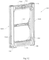
- FIGs. 1A , 1C , ID, 1H to 1J illustrating a workbench support systems in accordance with an example of the disclosed subject matter and generally designated 100.
- the workbench support systems 100 is configured with at least one utility portion 118 (as will be discussed) and deployable between an operative position seen e.g. in Figs. 1A and 1H and a collapsed position seen e.g. in Figs. 1C and 1D . This collapsed position will be interchangeably referred to as a stowed position.
- the disclosed subject matter further refers to workbench assemblies comprising any one of the workbench support systems of the present subject matter and a utility member generally designated 120 (seen in e.g. Fig. 1A ) configured for articulation to the support system 100 in an operative position (as seen e.g. in Fig. 1B ) and further configured to be stowed within the support system 100 when in the collapsed position (as seen e.g. in Figs. 1E-1G ).
- the thickness of the assembly 200 in the stowed position does not exceed the thickness of the workbench support system 100 when collapsed.
- the workbench support assembly can be configured to receive the utility member between the frames 115 such that larger utility members can be used.
- the workbench support system can be stowed within a respective cavity formed at the bottom surface of the utility member (not shown).
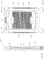
- the workbench support system 100 comprises a first set of two substantially parallel disposed support legs 102A and a second set of two support legs 102B.
- the two support legs of each set 102A and 102B are connected at their top end with a connecting support bar 108A and 108B respectively and at their bottom end with a support bar 110A and 110B, respectively, together constituting a substantially rectangular frames 115A and 115B, respectively.
- the first set of support legs 102A and the second set of support legs 102B are interconnected by a link member 117 disposed at each side of the support system.
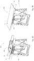
- the link member 117 comprising at least two connecting bars 106A and 106B pivotable one with respect to the other at a pivot point 112 such that one free end 116 of each of the at least two connecting bars is pivotably connected at a lower end of the support legs 102A and 102B while the other free end 138 of the connecting bars 106A and 106B is slidingly displacable over the upper end of the opposite set of support legs 102B and 102A.
- the sliding displacement is facilitated by a rail system 114 provided at an inner face of each of the support legs. Adjacent the displacement rail there is further provided a storage rail 114' (best seen in Figs.
- first fully deployed position seen e.g. in Fig. 1A and 1H the link members 117 are in a fully deployed configuration connectably spacing apart the first set of support legs 102A and the second set of support legs 102B with the connecting bars 106A and 160B extending in diagonal therebetween and in the collapsed position the link members 117 being disposed substantially in parallel to the first set of support legs 102A and the second set of support legs102B.
- each of the support legs is provided with a rail system 114.
- This rail system 114 allows the end 138 of each of the connecting bars 106a and 106B to slide therewithin thereby adjusting the distance between the two sets of support legs 102A and 102B.
- the free ends 138 of the connecting bars 106A and 106B on each side of the system 100 slide in the direction indicated by arrow U in Fig. 1H .
- the pivot 112 along with the pivot points at the ends 116 of the connecting bars in association with the set of support legs translate the position of the connecting bars from diagonal to vertical configuration, bringing together the two frames 115A and 115B such that the inner faces of the frames are substantially flush with each other and the opposite support legs abutting each other.
- a storage rail 114' adjacent each rail 114 so as to stow the connecting bar connected at an opposite end to the respective rail 114 (best seen in Fig. 1I and 1J ).
- the work bench support system is further provided with at least one utility portion designated 118 in Figs. 1A to 1J .
- This utility portion is in the form of outwardly protruding support members provided at the top edges of the support bars 108A and 108B. These support members 118 are configured for supporting a workbench surface, a workspace and the like.
- the utility portion is in the form of a flat protruding member it will be appreciated that other types of supports are envisioned such as a notch configured for supporting an elongate workpiece (being for example a V-notch, a right-angled notch, a semicircular notch and the like some of which will be discussed with respect to further examples of the present disclosed subject matter).
- a utility member generally designated 120 which constitutes a workbench surface for holding tools and refers to any sort of arrangement configured for supporting a workpiece or a worktool and supportable over the utility portion(e.g. Fig. 2A , 2B , 2E ).
- a utility member can be a unitary flat surface (e.g. a board, workbench tabletop) with or without workpiece/worktool supporting arrangement such as rails, slots, notches, openings, hooks etc.
- various examples of the utility member are illustrated in Figs. 1A , 1E , 1F , 1G , 2F to 2E etc.
- the utility member can be configured with modular work utilities, either fixed or replaceable.
- such work utilities can comprise T-slots ( Figs. 1A and IF), router plates, router fences, measurement indicia, coupling ports, etc.
- the utility member 120 is articulated to the workbench support system over the utility portion thereof via respective nooks 122A to 122D (seen in Fig. 1A(c) ), adapted to snuggly receive the support members 118. It will be appreciated that other types of articulations are possible including providing the utility member with an anti skid surface or suction cups etc to rest of the edge of the support bar 108. In accordance with an example illustrated e.g. in Fig.
- the workbench support system is further provided with a latch 103 configured to lock over the utility member securing it in place as seen in Fig. 1B in the locked position and Fig. 1I in the resting, unlocked position.
- This latch is optional and other means if any of locking mechanisms are envisioned, including locks, hooks etc.
- the utility member When the workbench support system is in a collapsed position (e.g. as seen in Figs. 1E to 1G ), the utility member is configured in its dimensions to be received within the space formed by frames constituted by the support bars 108A and 108B, 110A and 110B and the two sets of the support legs.
- the frame is provided with a locking mechanism for locking the utility member thereto, in the illustrated example this is achieved by the locking teeth 105 which are snapped into respective openings provided on the edges of the utility member, in this case constituted by the openings formed by the strength enhancing ribs at the side walls of the utility member 120. While in the examples of Figs.
- one side of the support bars 110A is provided with the teeth 105, as seen in fig. 1B , both support bars can be configured with the respective teeth 105 and 105' such that when the utility member is locked thereover, it snuggly locks over both support frames 110A and 110B.
- other locking mechanisms can be provided either as integral part of the system or the utility member or as an add-on mechanism.
- the assembly is compactly folded and can be easily stored and transported.
- the assembly can be provided with a carrying handle for example, e.g. element 107 provided on one of the frame 115B and extending between the two support legs thereof. It will be appreciated that other configurations are envisioned, e.g. a handle provided at the sides of the support frame, a retractable handle and the like.
- the workbench assembly 200 seen in Fig. 1E for example is configured with one or more organizers 130 (e.g. screw organizers) detachably attachable thereto. According to this particular example an organizer is detachably attachable at a bottom face of the utility member 120. The organizer can be configured for sealing attachment to the utility member.
- organizers 130 e.g. screw organizers
- the utility member can be configured with receptacles/compartments/trays configured at the top face thereof (not shown).
- such compartments can be drawer-like receptacles configured at side walls of the utility member.
- the utility member is provided with two horizontally extending channels 122 (i.e. extending substantially perpendicular to the support legs) configured to receive therethrough a workpiece W, as shown in Fig. 2A .
- the channels can have any desired geometrical shape and dimensions to allow passing through of the respective workpiece.
- the utility member 120 (as well as 420 described with reference to assembly 500) can be configured for detachably attaching thereto utility hooks e.g. as seen in figs. 6B and 6C with reference to workbench assembly 500.
- utility hooks can be used for example for mounting thereon various equipment/gear and for supporting beams which can facilitate for setting up an extended work surface, a scaffold, etc..
- the utility hooks can be configured for supporting rectangle cross-sectioned beams (e.g. 2X4 dimensional lumber).
- reference numeral 400 and 600 generally designate the workbench support assembly in accordance with another example of the disclosed subject matter.
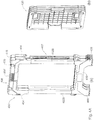
- a workbench support system 400 which as in the previous example is configured with a utility portion 418, 430 (as will be discussed) and deployable between an operative position seen e.g. in Figs. 3A and 3B and a collapsed position seen e.g. in Figs. 4A and 5 .
- the disclosed subject matter further refers to workbench assemblies 500 comprising the workbench support system 400 and a utility member generally designated 420 (seen in e.g. Fig. 3A ) configured for articulation to the support system 400 in an operable position (as seen e.g. in Fig. 3B ) and further configured to be stowed within the support system 400 when in the collapsed position (as seen e.g. in Figs. 4B and Fig. 5 ).
- the workbench support system 400 comprises a first set of two substantially parallel disposed support legs 402A and a second set of two support legs 402B.
- the two support legs of each set 402A and 402B are connected at their top end with a connecting support bar 408 and at their bottom end with a support bar 410, together constituting substantially rectangular side frames 415.
- the connecting bar 408 in this example is a sliding member, comprising two downwardly extending substantially vertical sleeve like cavities 404 connected by a horizontal bar 408', each cavity configured to be slidingly mounted on the respective support leg 102.
- the bottom bar 410 is fixedly attached to the opposite side of the support legs.
- the two frames 415 are interconnected by a link member 417 at each side.
- the link member 417 in the present example comprises two connecting bars 406A and 406B pivotable one with respect to the other at a pivot point 412 such that one free end 416 of each of the at least two connecting bars is pivotally connected at a lower end of the support legs 402A and 402B while the other free end 438 of the connecting bars 406A and 406B is pivotally attached to the sleeve 404 at the upper end of the opposite set of support legs 402B.
- the sliding displacement of the link member is facilitated by the movement of the sleeve 404 over the respective leg support.
- a first fully deployed position seen e.g. in Fig.
- the link members 417 are in a fully deployed configuration connectably spacing apart the first set of support legs 402A and the second set of support legs 402B with the connecting bars 406A and 406B extending in diagonal therebetween connected at a pivot point 412 forming a pivotal X -like link member 417 and in the collapsed position the link members 417 being disposed substantially in parallel to the first set of support legs 402A and the second set of support legs 402B.
- each of the support legs is provided with a sleeve like sliding member 404.
- This sleeve like sliding system allows the end 438 of each of the connecting bars 406a and 406B to slidingly extend form the diagonal position to a vertical position thereby adjusting the distance between the two sets of support legs 402A and 402B and consequently to bring together the two opposite frames 415.
- the ends 438 of the connecting bars 406A and 406B articulated to the respective sleeves 404 on each side of the system 400 slide in the direction indicated by arrow U in Fig. 3C .
- the distance can be defined H-h, where h is the length of the leg between the support bars 408 and 410 when in the expanded, operational position and H being the distance while in the collapsed position.
- the pivot 412 along with the pivot points at the ends 416 and 438 of the connecting bars in association with the set of support legs translate the position of the connecting bars from diagonal to vertical configuration, bringing together the two frames 415 such that the inner faces of the frames are substantially flush with each other and the opposite support legs abutting each other.
- the link members 417 extend at the outer side of adjacent set of support legs 402A and 402B.
- the workbench support system is provided with a utility portion 418 configured to secure a detachably attachable utility member (e.g. as seen in Figs. 3A and 4A (b) , although other types of utility members can be provided as disclosed with respect to any other example of the disclosed subject matter and as defined herein) thereon as illustrated in Figs. 3B to 3E .
- the utility member can be snuggly stowed within the space defined by the support bars and the support legs.
- the workbench support system further comprises a utility portion 430 in the form of a right - angled notch configured for supporting an elongate workpiece (best seen in fig. 5 and 6A in operation supporting a workpieces w).
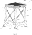
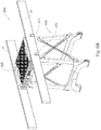
- the workbench support system 600 of the disclosed subject matter illustrated in Figs. 7A to 9D differs from the previous workbench support systems in that it is a combination of a support system and a sawhorse.
- the bottom part 610 of the support system frames 615 is provided with retractable and adjustable leg supports 611 and disposed between the frames there is provided a tray 680 configured for holding various articles, such as tools, screws etc.
- the workbench support system 600 is provided with a utility portion 618 configured to secure a detachably attachable utility member (not shown).
- the workbench support system 600 further comprises a utility portion 630 in the form of a right - angled notch configured for supporting an elongate workpiece w (best seen in fig. 9C and 9D in operation supporting a workpieces w).
- a further utility portion 432 is provide in the form of a v-like notch also configured to hold a workpiece as desired.
- the difference between the workbench support system 400 and the present example is in the configuration of the link member 617.
- the link members 617 in the present example comprise two connecting bars 606A and 606B pivotal one with respect to the other at a pivot point 612 such that one free end 638 of each of the at least two connecting bars is pivotally connected at an upper end of the support legs 602A and 602B in this example to the support bar 608 while the other free end 616 of the connecting bars 606A and 606B is pivotally attached to a slidable sleeve 604 disposed over the support legs 602a and 602B at a position lower than the upper connecting bar 608.
- the free end 616 connects to the sleeve 604 of the opposite set of support legs 602B to that of the end 638 thus forming a diagonal connection when in an extended position, with the two connecting bars 606A and 606B forming an X-like link member 617.
- the sliding displacement of the link member is facilitated by the movement of the sleeve 604 in the direction of arrow D over the respective leg support.
- each of the support legs is provided with a sleeve like sliding member 604.
- This sleeve like sliding system allows the end 416 of each of the connecting bars 606a and 606B to slidingly extend form the diagonal position to a vertical position thereby adjusting the distance between the two sets of support legs 602A and 602B and consequently to bring together the two opposite frames 615.
- the free ends 616 of the connecting bars 606A and 606B articulated to the respective sleeves 604 on each side of the system 600 slide in the direction indicated by arrow D in Fig. 6A .
- the pivot 612 along with the pivot points at the ends 616 and 638 of the connecting bars in association with the set of support legs translate the position of the connecting bars from diagonal to vertical configuration, bringing together the two frames 615 such that the inner faces of the frames are substantially flush with each other and the opposite support legs abutting each other.
- the link member 617 is disposed substantially at the upper portion of the support system to enhance the structural strength of the system when in operation, it can be positioned along the frame at any desired position.
- the frames are angled one with respect to the other, contributing to its saw horse like structure.
Landscapes
- Engineering & Computer Science (AREA)
- Mechanical Engineering (AREA)
- Workshop Equipment, Work Benches, Supports, Or Storage Means (AREA)
- Ladders (AREA)
Claims (14)
- Werkbankstützsystem (100), das mit einem Nutzabschnitt (118) versehen ist und zwischen mindestens einer ersten vollständig ausgeklappten Position und einer zweiten vollständig zusammengeklappten Position manipulierbar ist, wobei das Werkbankstützsystem (100) einen ersten Satz von Stützbeinen (102A, 402A, 602A) und einen zweiten Satz von Stützbeinen (102B, 402B, 602B) umfasst, wobei der erste Satz von Stützbeinen (102A, 402A, 602A) und der zweite Satz von Stützbeinen (102B, 402B, 602B) durch mindestens ein Verbindungselement (117, 417, 617) miteinander verbunden sind,dadurch gekennzeichnet, dass das Verbindungselement (117, 417, 617) mindestens zwei Verbindungsstangen (106A, 106B, 406A, 406B, 606A, 606B) aufweist, die relativ zueinander schwenkbar sind,so dass ein freies Ende (116, 616) jeder der mindestens zwei Verbindungsstangen (106A, 106B, 406A, 406B, 606A, 606B) an einem unteren Ende der Stützbeine (102A, 402A, 602A, 102B, 402B, 602B) schwenkbar verbunden ist,während das andere freie Ende (138, 638) der Verbindungsstangen (106A, 106B, 406A, 406B, 606A, 606B) gleitend über das obere Ende des gegenüberliegenden Satzes von Stützbeinen (102A, 402A, 602A, 102B, 402B, 602B) verschiebbar ist,
wobei sich in einer ersten vollständig ausgeklappten Position das mindestens eine Verbindungselement (117, 417, 617) in einer vollständig ausgeklappten Konfiguration befindet,wodurch der erste Satz von Stützbeinen (102A, 402A, 602A) und der zweite Satz von Stützbeinen (102B, 402B, 602B) verbindbar beabstandet wird und sich in diagonaler Richtung dazwischen erstreckt, undwobei in der zusammengeklappten Position die Verbindungselemente (117, 417, 617) im Wesentlichen parallel zu dem ersten Satz von Stützbeinen (102A, 402A, 602A) und dem zweiten Satz von Stützbeinen (102B, 402B, 602B) angeordnet sind. - Werkbankstützsystem (100) nach Anspruch 1, wobei in der zusammengeklappten Position die Verbindungselemente (117, 417, 617) vollständig innerhalb des Satzes von Stützbeinen (102A, 402A, 602A, 102B, 402B, 602B) aufgenommen und verstaut sind.
- Werkbankstützsystem (100) nach Anspruch 1, wobei sowohl der erste Satz als auch der zweite Satz der Stützbeine (102A, 402A, 602A, 102B, 402B, 602B) ein unteres Ende und ein oberes Ende aufweisen, wobei das obere Ende und/oder das untere Ende einen vertikal verschiebbaren Abschnitt aufweist undwobei in der zusammengeklappten Position die Verbindungsstangen (106A, 106B, 406A, 406B, 606A, 606B) die vertikal verschiebbaren Abschnitte gleitend verschieben.
- Werkbankstützsystem (100) nach Anspruch 3, wobei sich in der zusammengeklappten Position die Verbindungselemente an der Seite eines benachbarten Satzes von Stützbeinen (102A, 402A, 602A, 102B, 402B, 602B) erstrecken.
- Werkbankstützsystem (100) nach Anspruch 1, wobei das andere freie Ende (616) der Verbindungsstangen (606A, 606B) schwenkbar an einer verschiebbaren Hülse (604) angebracht ist,die über den Sätzen der Stützbeine (602A, 602B) an einer Position unterhalb der Verbindungsstangen (608) angeordnet ist,wodurch in einer ausgeklappten Position eine diagonale Verbindung hergestellt wird, wobei die beiden Verbindungsstangen (606A, 606B) ein X-artiges Verbindungselement (617) bilden.
- Werkbankstützsystem (100) nach einem der Ansprüche 1 bis 5, das ferner mindestens einen Nutzabschnitt (118) umfasst, der an den Oberkanten von Stützstangen (108A, 108B) vorgesehen ist, die zum Stützen eines Nutzelements konfiguriert sind.
- Werkbankstützsystem (100) nach einem der Ansprüche 1 bis 6, wobei ein Bodenteil (610) der Stützbeine (102A, 402A, 602A, 102B, 402B, 602B) mit einziehbaren und einstellbaren Beinstützen (611) versehen ist.
- Werkbankstützsystem (100) nach einem der Ansprüche 1 bis 7, das einen ersten Satz von zwei im Wesentlichen parallel angeordneten Stützbeinen (102A, 402A, 602A) und einen zweiten Satz von zwei Stützbeinen (102B, 402B, 602B) umfasst, wobei die zwei Stützbeine jedes Satzes an ihrem oberen Ende und ihrem unteren Ende mit einer Verbindungsstütze (108A, 108B, 110A, 110B, 408, 410) verbunden sind,die zusammen im wesentlichen rechteckige Tragrahmen (115A, 115B, 415) bilden.
- Werkbankstützsystem (100) nach Anspruch 8, wobei die Stützrahmen (115A, 115B, 415) in der Betriebskonfiguration parallel angeordnet oder relativ zueinander abgewinkelt sind.
- Werkbankstützsystem (100) nach einem der Ansprüche 1 bis 9, wobei das Verschieben durch Folgendes erleichtert wird:ein Schienensystem (114), das an einer Innenseite jedes der Stützbeine (102A, 402A, 602A, 102B, 402B, 602B) vorgesehen ist, undeine Lagerschiene (114'), die dafür konfiguriert ist, die Verbindungsstange (106A, 106B, 406A, 406B, 606A, 606B) festsitzend darin aufzunehmen, die dem gegenüberliegenden Satz von Beinen (102A, 402A, 602A, 102B, 402B, 602B) zugeordnet ist.
- Werkbankstützsystem (100) nach einem der Ansprüche 1 bis 10, das ferner mit einem Verriegelungsmechanismus versehen ist, der ein Nutzelement an dem Werkbankstützsystem (100) verriegelt, wobei der Verriegelungsmechanismus optional ein integraler Bestandteil des Systems oder des Nutzelements ist oder als Zusatzmechanismus dient.
- Werkbankstützsystem (100) nach einem der Ansprüche 1 bis 11, das ferner mit einem Tragegriff (107) versehen ist.
- Werkbankstützsystem (100) nach einem der Ansprüche 1 bis 12, das mit einem oder mehreren Organisatoren konfiguriert ist, die lösbar daran befestigbar sind (130).
- Werkbankstützsystem (100) nach einem der Ansprüche 1 bis 13, wobei der Nutzabschnitt (118) dafür konfiguriert ist, ein Nutzelement (120) aufzunehmen und zwischen einer Betriebsposition und einer zusammengeklappten Position einsetzbar ist, wobei das Nutzelement (120) zur Anlenkung an dem Trägersystem (100) in einer Betriebsposition konfiguriert ist und ferner dafür konfiguriert ist, in dem Trägersystem (100) verstaut zu werden, wenn es sich in der zusammengeklappten Position befindet, wobei die Dicke einer Baugruppe (200), die das Nutzselement (120) und das Stützsystem (100) in der verstauten Position umfasst, die Dicke des Werkbankstützsystems (100) nicht überschreitet.
Priority Applications (1)
| Application Number | Priority Date | Filing Date | Title |
|---|---|---|---|
| PL16726203T PL3291949T3 (pl) | 2015-05-04 | 2016-05-04 | System wsporczy stołu warsztatowego |
Applications Claiming Priority (2)
| Application Number | Priority Date | Filing Date | Title |
|---|---|---|---|
| US201562156544P | 2015-05-04 | 2015-05-04 | |
| PCT/IL2016/050470 WO2016178227A1 (en) | 2015-05-04 | 2016-05-04 | Workbench support system and a workbench assembly associated therewith |
Publications (2)
| Publication Number | Publication Date |
|---|---|
| EP3291949A1 EP3291949A1 (de) | 2018-03-14 |
| EP3291949B1 true EP3291949B1 (de) | 2019-08-14 |
Family
ID=56092964
Family Applications (1)
| Application Number | Title | Priority Date | Filing Date |
|---|---|---|---|
| EP16726203.9A Active EP3291949B1 (de) | 2015-05-04 | 2016-05-04 | Werkbankstützsystem |
Country Status (7)
| Country | Link |
|---|---|
| US (1) | US20180141203A1 (de) |
| EP (1) | EP3291949B1 (de) |
| CN (1) | CN107750199A (de) |
| CA (1) | CA2984728A1 (de) |
| IL (1) | IL255389A0 (de) |
| PL (1) | PL3291949T3 (de) |
| WO (1) | WO2016178227A1 (de) |
Cited By (1)
| Publication number | Priority date | Publication date | Assignee | Title |
|---|---|---|---|---|
| US11434070B2 (en) * | 2020-01-17 | 2022-09-06 | Ingo Scholz | Cargo optimizing device for shipping containers and box trucks |
Families Citing this family (5)
| Publication number | Priority date | Publication date | Assignee | Title |
|---|---|---|---|---|
| USD839449S1 (en) * | 2016-10-27 | 2019-01-29 | Keter Plastic Ltd. | Sawhorse |
| USD889926S1 (en) * | 2018-01-03 | 2020-07-14 | Black & Decker Inc. | Sawhorse |
| CN108705161A (zh) * | 2018-06-25 | 2018-10-26 | 浙江芊荷科技有限公司 | 一种电火花机床用加工制造工作台及其制造工作方法 |
| WO2022177790A1 (en) * | 2021-02-16 | 2022-08-25 | Milwaukee Electric Tool Corporation | Support structure for use with modular storage system |
| EP4294601A4 (de) | 2021-02-16 | 2025-06-04 | Milwaukee Electric Tool Corporation | Stützstruktur zur verwendung mit einem modularen lagersystem |
Citations (1)
| Publication number | Priority date | Publication date | Assignee | Title |
|---|---|---|---|---|
| WO2014177830A1 (en) * | 2013-05-02 | 2014-11-06 | Toolstream Limited | Apparatus for use with power tools |
Family Cites Families (10)
| Publication number | Priority date | Publication date | Assignee | Title |
|---|---|---|---|---|
| US1614818A (en) * | 1925-10-31 | 1927-01-18 | Harold R Basford | Folding stand |
| IT1054874B (it) * | 1976-02-19 | 1981-11-30 | Star Utensili Elett | Banco di lavoro ripiegabile |
| FR2804358B1 (fr) * | 2000-01-27 | 2002-04-12 | Triplex | Etabli pliant evolutif |
| US6659440B2 (en) | 2000-12-18 | 2003-12-09 | Zag Industries Ltd. | Portable support assembly for a workpiece |
| US7156356B2 (en) * | 2003-05-14 | 2007-01-02 | Blattner Robert R | Foldable stand |
| CN2649283Y (zh) * | 2003-07-17 | 2004-10-20 | 南京泉峰国际贸易有限公司 | 用于切割机器的可折叠支架 |
| US7090210B2 (en) * | 2003-08-05 | 2006-08-15 | Black & Decker Inc. | Folding bench with hand truck capabilities |
| EP1973707B1 (de) * | 2005-12-08 | 2012-10-31 | Robert Bosch GmbH | Rahmenanordnung für eine klappwerkbank |
| US8042794B2 (en) | 2008-07-02 | 2011-10-25 | Black & Decker Inc. | Workbench with saw horse |
| EP2767369B1 (de) * | 2013-02-15 | 2016-04-20 | The Stanley Works Israel Ltd. | Werkbankrahmen |
-
2016
- 2016-05-04 CA CA2984728A patent/CA2984728A1/en not_active Abandoned
- 2016-05-04 WO PCT/IL2016/050470 patent/WO2016178227A1/en not_active Ceased
- 2016-05-04 PL PL16726203T patent/PL3291949T3/pl unknown
- 2016-05-04 EP EP16726203.9A patent/EP3291949B1/de active Active
- 2016-05-04 US US15/571,673 patent/US20180141203A1/en not_active Abandoned
- 2016-05-04 CN CN201680034572.9A patent/CN107750199A/zh active Pending
-
2017
- 2017-11-01 IL IL255389A patent/IL255389A0/en unknown
Patent Citations (1)
| Publication number | Priority date | Publication date | Assignee | Title |
|---|---|---|---|---|
| WO2014177830A1 (en) * | 2013-05-02 | 2014-11-06 | Toolstream Limited | Apparatus for use with power tools |
Cited By (1)
| Publication number | Priority date | Publication date | Assignee | Title |
|---|---|---|---|---|
| US11434070B2 (en) * | 2020-01-17 | 2022-09-06 | Ingo Scholz | Cargo optimizing device for shipping containers and box trucks |
Also Published As
| Publication number | Publication date |
|---|---|
| US20180141203A1 (en) | 2018-05-24 |
| WO2016178227A1 (en) | 2016-11-10 |
| CA2984728A1 (en) | 2016-11-10 |
| PL3291949T3 (pl) | 2019-11-29 |
| EP3291949A1 (de) | 2018-03-14 |
| IL255389A0 (en) | 2017-12-31 |
| CN107750199A (zh) | 2018-03-02 |
Similar Documents
| Publication | Publication Date | Title |
|---|---|---|
| EP3291949B1 (de) | Werkbankstützsystem | |
| US8231119B2 (en) | Workbench with saw horse | |
| US7210510B2 (en) | Work bench | |
| EP2103397B1 (de) | Ausklappbarer Sägebock mit schwenkbaren, freitragenden Trageelementen | |
| US7415933B2 (en) | Collapsible worktable | |
| US20020125072A1 (en) | Height adjustable sawhorse | |
| US9814308B2 (en) | Leg assembly | |
| US20040250901A1 (en) | Collapsible stand | |
| US20180001466A1 (en) | Workbench and articles associated therewith | |
| US20040124036A1 (en) | Portable work stand | |
| US6546978B2 (en) | Portable table saw stand | |
| US7185738B1 (en) | Modular saw horse | |
| US5782279A (en) | Portable universal saw table | |
| US6729371B2 (en) | Workbench | |
| US5758744A (en) | Sawhorse | |
| CA1168286A (en) | Workpiece support and clamping assembly | |
| NZ531574A (en) | table with platforms projecting from at least three sides, each being adjustable longitudinally and vertically | |
| US20220288768A1 (en) | Collapsible portable table saw stand | |
| GB2356597A (en) | A workbench | |
| US3070138A (en) | Foldable work-bench | |
| GB2253180A (en) | Sawhorse and toolbox assembly | |
| US8403313B2 (en) | Work table having elevated support members | |
| EP1574298A1 (de) | Auflagetisch für einen Arbeitsplatz | |
| CA1276212C (en) | Saw horse | |
| AU2024219488A1 (en) | Universal Workers Bench |
Legal Events
| Date | Code | Title | Description |
|---|---|---|---|
| STAA | Information on the status of an ep patent application or granted ep patent |
Free format text: STATUS: THE INTERNATIONAL PUBLICATION HAS BEEN MADE |
|
| PUAI | Public reference made under article 153(3) epc to a published international application that has entered the european phase |
Free format text: ORIGINAL CODE: 0009012 |
|
| STAA | Information on the status of an ep patent application or granted ep patent |
Free format text: STATUS: REQUEST FOR EXAMINATION WAS MADE |
|
| 17P | Request for examination filed |
Effective date: 20171130 |
|
| AK | Designated contracting states |
Kind code of ref document: A1 Designated state(s): AL AT BE BG CH CY CZ DE DK EE ES FI FR GB GR HR HU IE IS IT LI LT LU LV MC MK MT NL NO PL PT RO RS SE SI SK SM TR |
|
| AX | Request for extension of the european patent |
Extension state: BA ME |
|
| DAV | Request for validation of the european patent (deleted) | ||
| DAX | Request for extension of the european patent (deleted) | ||
| STAA | Information on the status of an ep patent application or granted ep patent |
Free format text: STATUS: EXAMINATION IS IN PROGRESS |
|
| 17Q | First examination report despatched |
Effective date: 20180912 |
|
| GRAP | Despatch of communication of intention to grant a patent |
Free format text: ORIGINAL CODE: EPIDOSNIGR1 |
|
| STAA | Information on the status of an ep patent application or granted ep patent |
Free format text: STATUS: GRANT OF PATENT IS INTENDED |
|
| INTG | Intention to grant announced |
Effective date: 20190226 |
|
| GRAS | Grant fee paid |
Free format text: ORIGINAL CODE: EPIDOSNIGR3 |
|
| GRAA | (expected) grant |
Free format text: ORIGINAL CODE: 0009210 |
|
| STAA | Information on the status of an ep patent application or granted ep patent |
Free format text: STATUS: THE PATENT HAS BEEN GRANTED |
|
| AK | Designated contracting states |
Kind code of ref document: B1 Designated state(s): AL AT BE BG CH CY CZ DE DK EE ES FI FR GB GR HR HU IE IS IT LI LT LU LV MC MK MT NL NO PL PT RO RS SE SI SK SM TR |
|
| RAP1 | Party data changed (applicant data changed or rights of an application transferred) |
Owner name: KETER PLASTIC LTD. |
|
| REG | Reference to a national code |
Ref country code: GB Ref legal event code: FG4D |
|
| REG | Reference to a national code |
Ref country code: CH Ref legal event code: EP Ref country code: AT Ref legal event code: REF Ref document number: 1166482 Country of ref document: AT Kind code of ref document: T Effective date: 20190815 |
|
| REG | Reference to a national code |
Ref country code: IE Ref legal event code: FG4D |
|
| REG | Reference to a national code |
Ref country code: DE Ref legal event code: R096 Ref document number: 602016018604 Country of ref document: DE |
|
| REG | Reference to a national code |
Ref country code: NL Ref legal event code: MP Effective date: 20190814 |
|
| REG | Reference to a national code |
Ref country code: LT Ref legal event code: MG4D |
|
| PG25 | Lapsed in a contracting state [announced via postgrant information from national office to epo] |
Ref country code: PT Free format text: LAPSE BECAUSE OF FAILURE TO SUBMIT A TRANSLATION OF THE DESCRIPTION OR TO PAY THE FEE WITHIN THE PRESCRIBED TIME-LIMIT Effective date: 20191216 Ref country code: SE Free format text: LAPSE BECAUSE OF FAILURE TO SUBMIT A TRANSLATION OF THE DESCRIPTION OR TO PAY THE FEE WITHIN THE PRESCRIBED TIME-LIMIT Effective date: 20190814 Ref country code: HR Free format text: LAPSE BECAUSE OF FAILURE TO SUBMIT A TRANSLATION OF THE DESCRIPTION OR TO PAY THE FEE WITHIN THE PRESCRIBED TIME-LIMIT Effective date: 20190814 Ref country code: LT Free format text: LAPSE BECAUSE OF FAILURE TO SUBMIT A TRANSLATION OF THE DESCRIPTION OR TO PAY THE FEE WITHIN THE PRESCRIBED TIME-LIMIT Effective date: 20190814 Ref country code: FI Free format text: LAPSE BECAUSE OF FAILURE TO SUBMIT A TRANSLATION OF THE DESCRIPTION OR TO PAY THE FEE WITHIN THE PRESCRIBED TIME-LIMIT Effective date: 20190814 Ref country code: NL Free format text: LAPSE BECAUSE OF FAILURE TO SUBMIT A TRANSLATION OF THE DESCRIPTION OR TO PAY THE FEE WITHIN THE PRESCRIBED TIME-LIMIT Effective date: 20190814 Ref country code: BG Free format text: LAPSE BECAUSE OF FAILURE TO SUBMIT A TRANSLATION OF THE DESCRIPTION OR TO PAY THE FEE WITHIN THE PRESCRIBED TIME-LIMIT Effective date: 20191114 Ref country code: NO Free format text: LAPSE BECAUSE OF FAILURE TO SUBMIT A TRANSLATION OF THE DESCRIPTION OR TO PAY THE FEE WITHIN THE PRESCRIBED TIME-LIMIT Effective date: 20191114 |
|
| REG | Reference to a national code |
Ref country code: AT Ref legal event code: MK05 Ref document number: 1166482 Country of ref document: AT Kind code of ref document: T Effective date: 20190814 |
|
| PG25 | Lapsed in a contracting state [announced via postgrant information from national office to epo] |
Ref country code: AL Free format text: LAPSE BECAUSE OF FAILURE TO SUBMIT A TRANSLATION OF THE DESCRIPTION OR TO PAY THE FEE WITHIN THE PRESCRIBED TIME-LIMIT Effective date: 20190814 Ref country code: ES Free format text: LAPSE BECAUSE OF FAILURE TO SUBMIT A TRANSLATION OF THE DESCRIPTION OR TO PAY THE FEE WITHIN THE PRESCRIBED TIME-LIMIT Effective date: 20190814 Ref country code: LV Free format text: LAPSE BECAUSE OF FAILURE TO SUBMIT A TRANSLATION OF THE DESCRIPTION OR TO PAY THE FEE WITHIN THE PRESCRIBED TIME-LIMIT Effective date: 20190814 Ref country code: IS Free format text: LAPSE BECAUSE OF FAILURE TO SUBMIT A TRANSLATION OF THE DESCRIPTION OR TO PAY THE FEE WITHIN THE PRESCRIBED TIME-LIMIT Effective date: 20191214 Ref country code: GR Free format text: LAPSE BECAUSE OF FAILURE TO SUBMIT A TRANSLATION OF THE DESCRIPTION OR TO PAY THE FEE WITHIN THE PRESCRIBED TIME-LIMIT Effective date: 20191115 Ref country code: RS Free format text: LAPSE BECAUSE OF FAILURE TO SUBMIT A TRANSLATION OF THE DESCRIPTION OR TO PAY THE FEE WITHIN THE PRESCRIBED TIME-LIMIT Effective date: 20190814 |
|
| PG25 | Lapsed in a contracting state [announced via postgrant information from national office to epo] |
Ref country code: TR Free format text: LAPSE BECAUSE OF FAILURE TO SUBMIT A TRANSLATION OF THE DESCRIPTION OR TO PAY THE FEE WITHIN THE PRESCRIBED TIME-LIMIT Effective date: 20190814 |
|
| PG25 | Lapsed in a contracting state [announced via postgrant information from national office to epo] |
Ref country code: IT Free format text: LAPSE BECAUSE OF FAILURE TO SUBMIT A TRANSLATION OF THE DESCRIPTION OR TO PAY THE FEE WITHIN THE PRESCRIBED TIME-LIMIT Effective date: 20190814 Ref country code: RO Free format text: LAPSE BECAUSE OF FAILURE TO SUBMIT A TRANSLATION OF THE DESCRIPTION OR TO PAY THE FEE WITHIN THE PRESCRIBED TIME-LIMIT Effective date: 20190814 Ref country code: DK Free format text: LAPSE BECAUSE OF FAILURE TO SUBMIT A TRANSLATION OF THE DESCRIPTION OR TO PAY THE FEE WITHIN THE PRESCRIBED TIME-LIMIT Effective date: 20190814 Ref country code: AT Free format text: LAPSE BECAUSE OF FAILURE TO SUBMIT A TRANSLATION OF THE DESCRIPTION OR TO PAY THE FEE WITHIN THE PRESCRIBED TIME-LIMIT Effective date: 20190814 Ref country code: EE Free format text: LAPSE BECAUSE OF FAILURE TO SUBMIT A TRANSLATION OF THE DESCRIPTION OR TO PAY THE FEE WITHIN THE PRESCRIBED TIME-LIMIT Effective date: 20190814 |
|
| PG25 | Lapsed in a contracting state [announced via postgrant information from national office to epo] |
Ref country code: IS Free format text: LAPSE BECAUSE OF FAILURE TO SUBMIT A TRANSLATION OF THE DESCRIPTION OR TO PAY THE FEE WITHIN THE PRESCRIBED TIME-LIMIT Effective date: 20200224 Ref country code: SM Free format text: LAPSE BECAUSE OF FAILURE TO SUBMIT A TRANSLATION OF THE DESCRIPTION OR TO PAY THE FEE WITHIN THE PRESCRIBED TIME-LIMIT Effective date: 20190814 Ref country code: SK Free format text: LAPSE BECAUSE OF FAILURE TO SUBMIT A TRANSLATION OF THE DESCRIPTION OR TO PAY THE FEE WITHIN THE PRESCRIBED TIME-LIMIT Effective date: 20190814 Ref country code: CZ Free format text: LAPSE BECAUSE OF FAILURE TO SUBMIT A TRANSLATION OF THE DESCRIPTION OR TO PAY THE FEE WITHIN THE PRESCRIBED TIME-LIMIT Effective date: 20190814 |
|
| REG | Reference to a national code |
Ref country code: DE Ref legal event code: R097 Ref document number: 602016018604 Country of ref document: DE |
|
| PLBE | No opposition filed within time limit |
Free format text: ORIGINAL CODE: 0009261 |
|
| STAA | Information on the status of an ep patent application or granted ep patent |
Free format text: STATUS: NO OPPOSITION FILED WITHIN TIME LIMIT |
|
| PG2D | Information on lapse in contracting state deleted |
Ref country code: IS |
|
| PGFP | Annual fee paid to national office [announced via postgrant information from national office to epo] |
Ref country code: DE Payment date: 20200428 Year of fee payment: 5 Ref country code: FR Payment date: 20200512 Year of fee payment: 5 |
|
| 26N | No opposition filed |
Effective date: 20200603 |
|
| PG25 | Lapsed in a contracting state [announced via postgrant information from national office to epo] |
Ref country code: SI Free format text: LAPSE BECAUSE OF FAILURE TO SUBMIT A TRANSLATION OF THE DESCRIPTION OR TO PAY THE FEE WITHIN THE PRESCRIBED TIME-LIMIT Effective date: 20190814 |
|
| PGFP | Annual fee paid to national office [announced via postgrant information from national office to epo] |
Ref country code: PL Payment date: 20200428 Year of fee payment: 5 Ref country code: GB Payment date: 20200430 Year of fee payment: 5 |
|
| PG25 | Lapsed in a contracting state [announced via postgrant information from national office to epo] |
Ref country code: CH Free format text: LAPSE BECAUSE OF NON-PAYMENT OF DUE FEES Effective date: 20200531 Ref country code: MC Free format text: LAPSE BECAUSE OF FAILURE TO SUBMIT A TRANSLATION OF THE DESCRIPTION OR TO PAY THE FEE WITHIN THE PRESCRIBED TIME-LIMIT Effective date: 20190814 Ref country code: LI Free format text: LAPSE BECAUSE OF NON-PAYMENT OF DUE FEES Effective date: 20200531 |
|
| REG | Reference to a national code |
Ref country code: BE Ref legal event code: MM Effective date: 20200531 |
|
| PG25 | Lapsed in a contracting state [announced via postgrant information from national office to epo] |
Ref country code: LU Free format text: LAPSE BECAUSE OF NON-PAYMENT OF DUE FEES Effective date: 20200504 |
|
| PG25 | Lapsed in a contracting state [announced via postgrant information from national office to epo] |
Ref country code: IE Free format text: LAPSE BECAUSE OF NON-PAYMENT OF DUE FEES Effective date: 20200504 |
|
| PG25 | Lapsed in a contracting state [announced via postgrant information from national office to epo] |
Ref country code: BE Free format text: LAPSE BECAUSE OF NON-PAYMENT OF DUE FEES Effective date: 20200531 |
|
| REG | Reference to a national code |
Ref country code: DE Ref legal event code: R119 Ref document number: 602016018604 Country of ref document: DE |
|
| GBPC | Gb: european patent ceased through non-payment of renewal fee |
Effective date: 20210504 |
|
| PG25 | Lapsed in a contracting state [announced via postgrant information from national office to epo] |
Ref country code: GB Free format text: LAPSE BECAUSE OF NON-PAYMENT OF DUE FEES Effective date: 20210504 Ref country code: DE Free format text: LAPSE BECAUSE OF NON-PAYMENT OF DUE FEES Effective date: 20211201 |
|
| PG25 | Lapsed in a contracting state [announced via postgrant information from national office to epo] |
Ref country code: MT Free format text: LAPSE BECAUSE OF FAILURE TO SUBMIT A TRANSLATION OF THE DESCRIPTION OR TO PAY THE FEE WITHIN THE PRESCRIBED TIME-LIMIT Effective date: 20190814 Ref country code: FR Free format text: LAPSE BECAUSE OF NON-PAYMENT OF DUE FEES Effective date: 20210531 Ref country code: CY Free format text: LAPSE BECAUSE OF FAILURE TO SUBMIT A TRANSLATION OF THE DESCRIPTION OR TO PAY THE FEE WITHIN THE PRESCRIBED TIME-LIMIT Effective date: 20190814 |
|
| PG25 | Lapsed in a contracting state [announced via postgrant information from national office to epo] |
Ref country code: MK Free format text: LAPSE BECAUSE OF FAILURE TO SUBMIT A TRANSLATION OF THE DESCRIPTION OR TO PAY THE FEE WITHIN THE PRESCRIBED TIME-LIMIT Effective date: 20190814 |
|
| PG25 | Lapsed in a contracting state [announced via postgrant information from national office to epo] |
Ref country code: PL Free format text: LAPSE BECAUSE OF NON-PAYMENT OF DUE FEES Effective date: 20210504 |