EP3291973B1 - Dispositif de depose de fibres et procede pour deposer une gerbe de fibres sur une piece - Google Patents
Dispositif de depose de fibres et procede pour deposer une gerbe de fibres sur une piece Download PDFInfo
- Publication number
- EP3291973B1 EP3291973B1 EP16708641.2A EP16708641A EP3291973B1 EP 3291973 B1 EP3291973 B1 EP 3291973B1 EP 16708641 A EP16708641 A EP 16708641A EP 3291973 B1 EP3291973 B1 EP 3291973B1
- Authority
- EP
- European Patent Office
- Prior art keywords
- fiber
- laying
- fibre
- workpiece
- laying machine
- Prior art date
- Legal status (The legal status is an assumption and is not a legal conclusion. Google has not performed a legal analysis and makes no representation as to the accuracy of the status listed.)
- Active
Links
Images


Classifications
-
- B—PERFORMING OPERATIONS; TRANSPORTING
- B29—WORKING OF PLASTICS; WORKING OF SUBSTANCES IN A PLASTIC STATE IN GENERAL
- B29C—SHAPING OR JOINING OF PLASTICS; SHAPING OF MATERIAL IN A PLASTIC STATE, NOT OTHERWISE PROVIDED FOR; AFTER-TREATMENT OF THE SHAPED PRODUCTS, e.g. REPAIRING
- B29C70/00—Shaping composites, i.e. plastics material comprising reinforcements, fillers or preformed parts, e.g. inserts
- B29C70/04—Shaping composites, i.e. plastics material comprising reinforcements, fillers or preformed parts, e.g. inserts comprising reinforcements only, e.g. self-reinforcing plastics
- B29C70/28—Shaping operations therefor
- B29C70/30—Shaping by lay-up, i.e. applying fibres, tape or broadsheet on a mould, former or core; Shaping by spray-up, i.e. spraying of fibres on a mould, former or core
- B29C70/38—Automated lay-up, e.g. using robots, laying filaments according to predetermined patterns
- B29C70/382—Automated fiber placement [AFP]
- B29C70/384—Fiber placement heads, e.g. component parts, details or accessories
-
- B—PERFORMING OPERATIONS; TRANSPORTING
- B29—WORKING OF PLASTICS; WORKING OF SUBSTANCES IN A PLASTIC STATE IN GENERAL
- B29C—SHAPING OR JOINING OF PLASTICS; SHAPING OF MATERIAL IN A PLASTIC STATE, NOT OTHERWISE PROVIDED FOR; AFTER-TREATMENT OF THE SHAPED PRODUCTS, e.g. REPAIRING
- B29C70/00—Shaping composites, i.e. plastics material comprising reinforcements, fillers or preformed parts, e.g. inserts
- B29C70/04—Shaping composites, i.e. plastics material comprising reinforcements, fillers or preformed parts, e.g. inserts comprising reinforcements only, e.g. self-reinforcing plastics
- B29C70/28—Shaping operations therefor
- B29C70/30—Shaping by lay-up, i.e. applying fibres, tape or broadsheet on a mould, former or core; Shaping by spray-up, i.e. spraying of fibres on a mould, former or core
- B29C70/38—Automated lay-up, e.g. using robots, laying filaments according to predetermined patterns
- B29C70/382—Automated fiber placement [AFP]
-
- B—PERFORMING OPERATIONS; TRANSPORTING
- B29—WORKING OF PLASTICS; WORKING OF SUBSTANCES IN A PLASTIC STATE IN GENERAL
- B29C—SHAPING OR JOINING OF PLASTICS; SHAPING OF MATERIAL IN A PLASTIC STATE, NOT OTHERWISE PROVIDED FOR; AFTER-TREATMENT OF THE SHAPED PRODUCTS, e.g. REPAIRING
- B29C70/00—Shaping composites, i.e. plastics material comprising reinforcements, fillers or preformed parts, e.g. inserts
- B29C70/04—Shaping composites, i.e. plastics material comprising reinforcements, fillers or preformed parts, e.g. inserts comprising reinforcements only, e.g. self-reinforcing plastics
- B29C70/28—Shaping operations therefor
- B29C70/54—Component parts, details or accessories; Auxiliary operations, e.g. feeding or storage of prepregs or SMC after impregnation or during ageing
- B29C70/545—Perforating, cutting or machining during or after moulding
Definitions
- the invention relates to a fiber laying machine and a method for laying a fiber web on a workpiece.
- the fiber laying machine has a three-axis table which is rotatable about a vertical axis of rotation relative to a fiber laying head and can be moved linearly in two directions.
- a vacuum table that serves as a smooth tool surface is arranged on the three-axis table.
- the fiber laying head is fixedly arranged on a machine frame above the vacuum table and has guide rails for a fiber sliver which can be displaced in a vertical direction by means of a linear actuator in order to deliver the fiber sliver to the tool surface.
- a workpiece is understood to mean any substrate onto which the fibers are systematically applied.
- a base can be a flat surface, for example in the form of a later removable film or a slide-coated surface of a carrier from which the fiber structure is later detached.
- a partially completed fiber structure or another preliminary stage of a product forms the with Fibers to be occupied is a workpiece within the meaning of the invention.
- the base can be a pre-formed molding tool in which a defined shape of a later underside of the fiber structure is formed.
- the individual fiber strands are generally preferably already pre-coated with a binding agent when they are present in the fiber supply unit.
- a binding agent when they are present in the fiber supply unit.
- Such pre-coated fibers allow a particularly controlled gluing or connection to the fiber scrim, the amount of binder being optimally dosed at all times.
- a heating device for example in the form of a heat radiator, can be provided on the laying head.
- the feeding of pre-coated fibers to the laying head is associated with specific requirements compared to uncoated fibers.
- the configuration according to the invention of a fiber laying machine can therefore particularly optimize the fiber transport for coated fibers.
- Such binders are also referred to as matrix in specialist circles.
- a releasable clamping device is understood to mean any device which, in a clamped state, can exert sufficient holding forces on the fiber strands in order to reliably pull them out of the fiber supply unit against their friction-related resistance.
- a fiber supply unit is understood to mean any storage area for dispensing the fiber strands.
- the respective fiber strands can be wound onto exchangeable spools.
- the fiber supply unit also includes deflections of the fiber strands, by means of which they are fed to the movable laying head. A positioning of the exchangeable bobbins or a bobbin bearing relative to the laying head is largely freely selectable as a result.
- the bobbins can sit on axes of rotation that are driven counter to an unwinding direction, the drives of the axes of rotation having a torque limit.
- the torque can be limited, for example, by a friction clutch or by a torque-dependent control of an electric drive. In this way, the respective fiber strand can be kept in a defined pretension when required, in particular during unwinding.
- the fiber supply unit can generally preferably have one or more dancer magazines in order to keep the transport of the fiber strands under a defined tension and to equalize it.
- the workpiece is accommodated in the fiber laying machine so that it can pivot about an axis, so that the laying direction of the fibers can be changed adjustably relative to the workpiece.
- a holder of the workpiece can also have other movements, for example in a plane parallel to the laying direction.
- the fiber supply unit is arranged in a stationary manner. This allows a large supply of fiber strands with good maintenance access.
- the laying head can only be moved in exactly one plane relative to the fiber supply unit. Such a limitation of the movement of the laying head in a plane can be implemented with relatively simple means for guiding the fiber strands between the laying head and the fiber supply unit.
- the clamping device is released during the laying of the section of the fiber web.
- a length of the fiber web which is brought forward by the laying stroke and is located in a storage area between the fiber supply unit and the laying head is laid.
- the laying head moves mainly in the opposite direction of the movement by means of which the fiber web was pulled forward.
- the clamping device comprises at least one, particularly preferably two, clamping rollers that interact with one another.
- the use of pinch rollers reduces the accumulation of binder abrasion and fibers and enables a breakaway torque to be established in a simple manner to protect the system in the event of a malfunction.
- the pinch rollers can be equipped with a freewheel against the direction of pulling forward. This allows the pinch rollers For example, they can still be pressed against one another when a conveying member arranged downstream of the clamping rollers is already pulling the fiber strands forwards for laying.
- the pinch rollers are only released shortly after the start of such a further pulling-out in order to make the fiber guidance more uniform overall.
- a generally advantageously designed laying head comprises two feeds that run at an angle to one another, a first group of fiber strands being guided into a crossing area by means of a first of the infeeds and a second group of fiber strands being fed into a crossing area by means of the second of the feeders in order to feed the two groups of fiber strands to the fiber web unite.
- the groups of fiber strands can be offset perpendicular to the laying direction by one fiber strand width, and the combined groups of fiber strands can be homogenized, for example, by means of a compacting roller and applied to the workpiece.
- Such a laying head with two guides is preferably designed essentially mirror-symmetrically with respect to a center plane with regard to the alignment of the guides.
- the fibers can be separated by means of a cutting device arranged on the laying head, the cutting device comprising a plurality of separately controllable cutting members which can cut off different parts of the fibers transversely to the laying direction.
- the shape of the beginning and / or the end of the respectively laid web can generally be designed, so that even with workpieces of any shape there is at most a slight overhang or missing position of the fiber web at the edge.
- the cutting device has an actuator element for actuating at least one of the cutting elements, the actuator element being designed separately from the cutting element.
- the actuator element is particularly preferably arranged on an upper part of the laying head that can be detached for maintenance purposes.
- Such an upper part can, for example, be designed to be pivotable relative to a lower part, so that the cutting members subject to wear and possibly further mechanical elements of the laying head are easily accessible in the lower part.
- At least one pre-conveyor roller for driven feed is provided on the laying head, the pre-conveyor roller being arranged between the clamping device and an exit-side compacting roller of the laying head.
- the driven feed of the fiber strands is used for a particularly uniform application of the fiber web.
- the pre-feed roller is used to feed an end of the fiber web cut off in the laying head to the workpiece in order to start laying a new fiber web.
- the fiber laying machine is built entirely on a machine frame. This allows a simple relocation or replacement of the entire fiber laying machine in a production plant, if necessary, without the machine having to be dismantled in individual parts. Such a structure also favors the integration of the fiber laying machine into an automated production system.
- the fiber laying machine also advantageously has a climatically closed housing.
- this is to be understood as meaning that at least one area of the fiber laying machine surrounding the workpiece is provided with controlled air conditioning within the housing.
- air conditioning is particularly important for a good result during and immediately after the laying of fiber webs.
- Air conditioning in the sense of the invention also includes mere temperature control without influencing air humidity.
- the workpiece is preferably arranged on a pallet that can be transported automatically.
- a pallet is to be understood as any exchangeable carrier for the workpiece.
- transport space can be saved in that a surface of the pallet carrying the workpiece is inclined at an angle of less than 30 degrees with respect to a vertical. This includes in particular a vertical alignment of the surface. In this way a large room height in a production hall can be used without taking up too much space in width when transporting and feeding the pallet with the workpiece. In this sense, it can also be provided that the laying direction runs in a plane that is less than 30 degrees inclined to the vertical.
- This process ensures that the fibers are evenly deposited on the workpiece, without unwanted forces being introduced by a simultaneous pulling out of the fiber supply unit.
- the speed at which the fibers are fed and the speed at which they are laid can be set independently of one another, so that the overall process is optimized.
- the fibers are pulled out in the course of a first, forward movement of the laying head, during which there is no contact with the workpiece.
- the laying head is then placed on the workpiece so that the pulled fibers are deposited on the workpiece by means of a backward movement.
- the method is particularly preferably carried out by means of a fiber laying machine according to the invention.
- each of the specific features of a fiber laying machine according to the invention is suitable as an individual feature for improving a method according to the invention.
- step c. moved by means of a driven pre-conveyor roller with respect to the laying head, the fibers in particular not being pulled out of the fiber supply unit by means of the pre-conveyor roller.
- an initial advance at the start of the laying process can be achieved in a simple manner.
- any number of intermediate steps can be provided between the above-mentioned process steps. In the context of all the steps envisaged, it must in particular be ensured that there is always some kind of fixation of the fibers in order to prevent the fibers from leaving the fiber laying head in an uncontrolled manner.
- a system for manufacturing fiber composite components comprising at least one first fiber laying machine for applying fiber layers to a workpiece; and another processing station, different from the fiber laying machine, for modifying the workpiece, wherein the workpiece can be brought both to the fiber laying machine and to the further processing station by means of an automated conveying device.
- fiber laying machines have been used as single machines for the production of highly individual and complex components in small numbers.
- the preferred connection of a fiber laying machine to an automated production of workpieces is provided.
- At least one fiber laying machine of a preferred system is designed as a fiber laying machine according to the invention.
- a preferred system can also have several fiber laying machines of various types in order to optimize the process of workpiece production.
- the system comprises a second fiber laying machine which is spatially separated from the first fiber laying machine and is connected to the first fiber laying machine by means of the automated conveyor device.
- the at least two fiber laying machines are structurally identical.
- the fiber laying machines are provided as parallel processing stations that carry out the same processing steps on workpieces that are processed simultaneously. This allows the throughput to be increased and adapted to a possibly higher throughput of other processing stations.
- the fiber laying machines as sequential processing stations, carry out various processing steps on a workpiece one after the other. In this way, the production of the workpiece can be further optimized and, in particular, other processing steps can be carried out between the processing operations in the fiber laying machines.
- the system comprises at least one buffer station for receiving, storing and passing on several workpieces.
- This allows a significantly improved logistics in an automated production with high throughput.
- the workpieces preferably remain on their pallets in the buffer stations.
- the further processing station comprises at least one selected from the group of forming device, temperature chamber and / or painting device.
- a processing station is advantageously combined with the fiber laying machine in an automated form, particularly for the production of series parts for automobiles or aircraft.
- the automated conveying device preferably comprises a loading device, by means of which the fiber laying machine can be loaded and unloaded from only one side. This allows the workpiece to be moved in and out of the fiber laying machine in the manner of a dead end.
- the loading device can be used to simultaneously change a machined workpiece with an unmachined workpiece.
- the loading device can be designed as a rotary changing device which comprises a rotatable holder for receiving at least two workpieces.
- a fiber laying machine which is combined with a loading device described above, by means of which the fiber laying system can be loaded and unloaded from only one side. It goes without saying that such a fiber laying machine can also comprise any of the further features of the fiber laying machines described above.
- a laying head of the fiber laying machine can be moved in a vertical plane, an angle between the plane and a loading path of the fiber laying machine being between 0 ° and 30 °.
- the loading path and the plane are particularly preferably angled by 0 °, that is to say arranged in parallel or on a line.
- the laying head can only move in the vertical plane.
- a loading path is generally understood to be a particularly straight section for the automated transport of the workpiece between an outer region of the fiber laying machine and a processing position of the workpiece.
- the loading path is thus on the one hand part of the automated conveying device and on the other hand a part of the fiber laying machine.
- a laying head of the fiber laying machine can be moved in a vertical plane, a fiber bobbin bearing of the fiber laying machine comprising a plurality of fiber bobbins with mutually parallel bobbin axes, an angle between the bobbin axes and the vertical plane being between 60 ° and 90 °. Due to the arrangement of the fiber bobbin bearings and corresponding fiber guides, this also allows a narrow fiber laying machine. The angle is particularly preferably approximately 90 °. In this way, the loading path, the laying head and the fiber reel bearings can be arranged almost in a line one behind the other.
- at least two fiber bobbin bearings are provided which are each assigned to a group of fiber strands and which are positioned next to one another.
- the configurations of the fiber laying machine described above with regard to the alignment of the plane of movement of the laying head, loading path and / or bobbin axes allow extensive freedom in terms of the structural design and spatial dimensioning.
- This relates in particular to the arrangement of further components of the fiber laying machine, in particular an electrical control unit and an air conditioning unit.
- a system for the production of fiber composite components comprising at least one first fiber laying machine for applying fiber layers to a workpiece; and another, identical or different processing station for modifying the workpiece; wherein the workpiece can be brought to the fiber laying machine as well as to the further processing station by means of an automated conveying device, wherein the conveying device comprises a loading device by means of which the fiber laying system can be loaded and unloaded from only one side.
- the loading device is particularly preferably designed as a rotary changing device which comprises a rotatable holder for receiving at least two workpieces.
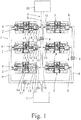
- a system for the production of fiber composite components has several fiber laying machines 2 for producing fiber layers 3.
- the fiber laying machines 2 are identical.
- the fiber laying system 1 has, for example, six structurally identical fiber laying machines 2, which are arranged in two groups. Each group has three fiber laying machines 2 which are arranged parallel to one another.
- the fiber laying installation 1 has a conveyor device 4, 5.
- the conveying device has, for example, several conveying carriages 4 which can be moved on a guide 5.
- the guide 5 has a loading section 6 which runs from a receiving point 7 to a respective loading side 8 of the fiber laying machine 2.
- At least one conveying carriage 4 is movably arranged on the loading section 6.
- the guide 5 also has an unloading section 9 which runs from a respective unloading side 10 of the fiber laying machine 2 to a depositing point 11.
- At least one conveying carriage 4 is movably arranged on the unloading section 9.
- workpieces 12, i.e. objects to be covered with fibers 13 can be moved from the receiving point 7 to the loading sides 8 and workpieces 12 covered with fibers 13 can be moved from the unloading sides 10 to the depositing point 11.
- the workpieces 12 are arranged on pallets 14.
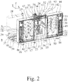
- the fiber laying machines 2 are structurally identical, so that only one of the fiber laying machines 2 is described below.
- the fiber laying machine 2 has a machine frame 15 with a machine bed 16 and cross members 17, 18 arranged thereon.
- the machine bed 16 extends essentially in a horizontal x-direction and a horizontal y-direction running perpendicular thereto.
- the cross members 17, 18 run parallel to the y-direction and are arranged on the machine bed 16 at a distance in the x-direction.
- the cross members 17, 18 are each arranged at both ends by means of longitudinal supports 19 in a z-direction above the machine bed 16.
- the z direction runs perpendicular to the x and y directions, so that the x, y and z directions form a Cartesian coordinate system.
- Two X-guide rails 20 are arranged on the machine bed 16, which extend in the x-direction and are spaced apart from one another in the y-direction are.
- An x slide 21 is mounted on the x guide rails 20 and can be moved by means of an x drive motor 22 along the x direction between the loading side 8 and the unloading side 10.
- the X-guide rails 20 extend in the x-direction along the entire machine bed 16.
- a tool table 23 is arranged on the x slide 21, which can be pivoted about a vertical pivot axis 25 by means of a c drive motor 24.
- the vertical pivot axis 25 is also referred to as the c-axis.
- the c-axis 25 runs parallel to the z-direction.
- the tool table 23 is linearly displaceable exclusively in the x direction by means of the X slide 21.
- the tool table 23 is used to position the respective workpiece 12 relative to a fiber laying head 26 (hereinafter referred to as laying head).
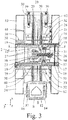
- the tool table 23 has several clamping units 27.
- the clamping units 27 are in Fig. 3 shown schematically.
- the clamping units 27 are basically known and are designed, for example, as zero point clamps 15.
- the clamping units 27 can be actuated electromechanically, hydraulically or pneumatically.
- the laying head 26 can be positioned in the z-direction above the tool table 23.
- the laying head 26 can be moved along the y-direction and along the z-direction.
- a y-slide 28 is mounted on the cross members 17, 18, which can be moved linearly along the y-direction by means of a y-drive motor 29.
- the y-slide 28 is mounted on y-guide rails 30 which are arranged on an upper side of the cross members 17, 18.
- the y slide 28 extends between the cross members 17, 18.
- a z slide 31 is arranged on the y slide 28 for moving the laying head 26 in the z direction.
- the z-slide 31 is mounted on z-guide rails 32 and can be moved along the z-direction by means of z-drive motors 33.
- the z-guide rails 32 run parallel to the z-direction and are spaced apart from one another in the x-direction.
- the laying head 26 is arranged on the z slide 31.
- the laying head 26 is preferably fastened in an exchangeable manner.
- the laying head 26 is exclusively in the y-direction linearly movable. A pivoting of the laying head 26 on the z-slide 31 is not possible.
- the laying head 26 can additionally or alternatively be pivotable about a pivot axis running parallel to the X direction, that is to say can form an a-axis. In this way, three-dimensional fiber fabrics 3 that are comparatively more strongly curved can be produced.
- the laying head 26 can be moved linearly along the z direction by means of the z slide 31 by at least 200 mm, in particular by at least 400 mm, and particularly preferably by at least 600 mm.
- a control unit 34 of the fiber laying machine 2 is designed in such a way that the fiber laying head 26 during the laying of fibers 13 by means of the z-slide 31 over its stroke by at least 50 mm, in particular by at least 100 mm, and in particular by at least 150 mm can be moved linearly.
- passage openings 35, 36 for the tool table 23 are formed below the cross members 17, 18 and between the respective associated longitudinal supports 19.
- a first pallet handling unit 37 is arranged on the loading side 8
- a second pallet handling unit 38 is arranged for the automatic unloading of mold pallets 14 from the tool table 23 on the unloading side 10.
- the handling units 37, 38 are attached to the end of the machine bed 16 along the x direction.
- the pallet handling units 37, 38 are designed as lifting units which are used to raise and lower pallets 14.
- the pallet handling units 37, 38 have at least three, in particular at least four lifting elements 39.
- the lifting elements 39 have a piston 40 which can be displaced in an associated cylinder 41 along the z-direction.
- the lifting elements 39 can be actuated electromechanically, pneumatically or hydraulically.
- the lifting elements 39 belonging to the respective pallet handling unit 37, 38 are actuated by means of the control unit 34 actuated synchronously to raise or lower a mold pallet 14.
- the fiber laying machine 2 has a fiber supply unit 42 for providing the fibers 13 to be laid.
- the fiber supply unit 42 has two fiber reel bearings 43, 44, a first fiber reel storage 43 being arranged in the x-direction next to the first transverse support 17 and a second fiber reel storage 44 being arranged next to the second transverse support 18.
- the fiber reel bearings 43, 44 are fastened to the machine bed 16 at the ends in the y direction.
- the fiber reel bearings 43, 44 each have a plurality of fiber reel holders 45 for fiber reels 46.
- the fiber bobbins 46 are arranged on a respective fiber bobbin holder 45 and rotatably mounted about a respective horizontal axis of rotation 47. The respective horizontal axis of rotation 47 runs parallel to the y-direction.
- the fibers 13 are each guided in the form of a fiber strand to the laying head 26 from the fiber bobbins. At the laying head, the individual fiber strands are brought together to form a fiber web and homogenized before the fiber web is applied to the workpiece.
- the axes of rotation 47 of the fiber bobbin holders are in the present case equipped with a drive so that the bobbins sit on axes 47 driven against an unwinding direction, the drives of the axes 47 having a torque limitation.
- the torque can be limited, for example, by a friction clutch or by a torque-dependent control of an electric drive. In this way, the respective fiber strand can be kept in a defined pretension when required, in particular during unwinding.
- the fibers or fiber strands 13 can be fed via guide elements 50 in the form of guide rollers to a respective dancer magazine 48, 49, which is used to compensate for changes in a tensile stress acting on the fibers 13.
- the respective dancer magazine 48, 49 has deflection elements 51 in the form of deflection rollers, which can be displaced along the z-direction and which pretension the fibers 13 by means of weights.
- the deflection elements 51 are also referred to as dancers.
- the displacement of the deflecting elements 51 makes it possible to compensate for dynamic effects which, on the one hand, are caused by the inertia of the fiber coils 46 are caused and on the other hand are caused by an uneven conveyance of the fibers 13 in the case of cutting individual fibers 13 during the laying down of fibers 13.
- the fibers 13 can be deflected via guide elements 53 in the form of guide rollers and can be guided out of the respective fiber reel store 43, 44.
- the position of the deflecting elements 51 is regulated when the dancer magazines 48, 49 are in operation.
- sensors 52 are used, which determine the deflection in the z direction of the deflecting elements 51.
- the deflection in the z-direction is regulated around a target position in that the fiber bobbin holders 45 are equipped with a controllable brake.
- the brake is preferably a torque-limited drive that acts counter to the winding direction.
- the fibers 13 emerge from the fiber reel bearings 43, 44 in the x direction and are deflected in the y direction by vertically arranged deflecting elements 54 which form a vertical deflection axis.
- the deflection elements 54 are designed as deflection rollers.
- the deflection elements 54 are mounted on a support frame 55 which is fastened between the fiber reel bearings 43, 44.
- horizontal deflection elements 56 in the form of deflection rollers are arranged, which initially move the fibers 13 from the ⁇ -direction into the z-direction and then from the z-direction redirect in the ⁇ direction.
- the deflection elements 56 form horizontal deflection axes. Between the y-slide 28 and the fiber reel bearings 43, 44, further horizontal deflection elements 57 are arranged above the z-slide 31. The deflection elements 57 form horizontal deflection axes and deflect the fibers 13 from the y-direction in the z-direction to the laying head 26. The deflection elements 57 are designed as deflection rollers.
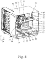
- the fiber laying machine 2 has a machine housing 58 which is only in the Fig. 3 and 4th is shown.
- the machine housing 58 delimits an interior space 59 in which the longitudinal supports 19 with the crossbeams 17, 18, the y-slide 28, the z-slide 31 and the fiber laying head 26 are arranged.
- the machine housing 58 has a first housing opening 60 towards the loading side 8 and a second housing opening 60, 61 towards the unloading side 10, which can be tightly closed and opened by respective cover elements 62.
- the housing openings 60, 61 and the associated cover elements 62 are shown in FIG Fig. 3 only outlined.
- the cover elements 62 are designed, for example, as doors or sectional aprons.
- the fiber laying machine 2 For air conditioning the interior 59, the fiber laying machine 2 has an air conditioning unit 63, which is arranged on the machine bed 16. Overall, a preferred climatically closed housing 58 is thereby formed.
- two further housing openings 64, 65 are formed in the machine housing 58, which open into the interior 59 between the respective adjacent longitudinal supports 19.
- the housing openings 64, 65 can be closed by means of doors 66.
- the mode of operation of the system for producing fiber composite components 1 and the fiber laying machine 2 is as follows:
- the fiber laying machines 2 are automatically loaded by means of the conveyor 4, 5 with pallets 14 on which workpieces 12 to be covered are arranged.
- the at least one conveyor carriage 4 moves from the receiving point 7 on the loading section 6 of the guide 5 to the respective loading side 8 of the fiber laying machine 2.
- Loading takes place in such a way that the conveying device 4, 5 feeds the pallet 14 to the first pallet handling unit 37.
- the first pallet handling unit 37 is preferably in a raised position. If the first pallet handling unit 37 is not in a raised position, it is transferred to a raised position before or after loading.
- the loading of the respective fiber laying machine 2 takes place parallel to the laying of fibers 13 and / or to unloading the tool table 23.
- a fiber scrim 3 is produced by means of the laying head 26.
- a pallet 14 with a workpiece 12 arranged thereon is clamped on the tool table 23 by means of the clamping units 27.
- the tool table 23 is during the fiber laying by means of the X carriage 21 linearly move along the x-direction and pivoted about the pivot axis 25 by means of the c-drive motor 24 to achieve a desired fiber orientation.
- the laying head 26 moves by means of the y slide 28 along the y direction and by means of the z slide 31 along the z direction.
- a three-dimensional fiber fabric 3 can also be produced if necessary.
- the x slide 21 is moved in the x direction to the unloading side 10.
- the second pallet handling unit 38 is in a lowered position.
- the lifting elements 39 of the second pallet handling unit 38 are then transferred from the lowered to the raised position, so that the pallet 14 with the fully loaded workpiece 12 is automatically unloaded from the tool table 23.
- the x slide 21 moves from the unloading side 10 to the loading side 8, where the first pallet handling unit 37 holds the next pallet 14 in the raised position. If the tool table 23 is located below the pallet 14, the lifting elements 39 of the first pallet handling unit 37 are transferred from the raised to the lowered position, whereby the pallet 14 is arranged on the tool table 23. The pallet 14 is then clamped on the tool table 23 by means of the clamping units 27. The tool table 23 is now moved for the next fiber laying process in the x direction to the laying head 26, so that the latter can begin the new fiber laying process.
- the lifting elements 39 of the first pallet handling unit 37 are returned to the raised position for a new loading.
- the fiber laying machine 2 is automatically unloaded by means of the conveying device 4, 5 which leads from the respective unloading side 10 to the depositing point 11.
- the unloading of the respective fiber laying machine 2 takes place parallel to the loading of the tool table 23 with a pallet 14 and a workpiece 12 arranged thereon and to be loaded and / or for the loading of the workpiece 12 with fibers 13.
- the conveyor carriage 4 takes over the pallet 14 and the workpiece 12 arranged on it from the second pallet handling unit 38 and moves from the respective unloading side 10 on the unloading section 9 of the guide 5 to the placement point 11.
- the lifting elements 39 of the second pallet- Handling units 38 are transferred to the lowered position after unloading, so that the tool table 23 can be unloaded again.
- the housing openings 60, 61 of the air-conditioned machine housing 58 are mainly closed by means of the cover elements 62 and are only opened when the tool table 23 moves from the loading side 8 to the laying head 26 or from the laying head 26 to the unloading side 10 or from the unloading side 10 to the loading side 8 is proceeded.
- the laying of the fibers 13 takes place unidirectionally when the laying head 26 is moved in the y-direction towards the fiber reel bearings 43, 44. During this displacement process, the distance between the vertical deflection elements 54 and the horizontal deflection elements 56 is shortened, so that no fibers 13 have to be pulled from the fiber reel bearings 43, 44 during the fiber laying process. As a result, the fiber laying can take place relatively quickly. When the fiber-laying head 26 moves backwards away from the fiber-spool bearings 43, 44, the fibers 13 are then drawn from the fiber-spool bearings 43, 44 for the next fiber-laying process. Changes in the tension of the fibers 13 are compensated for by means of the dancer magazines 48, 49.
- the fiber laying machines 2 are arranged in two groups in series with one another.
- the guide 5 is designed in such a way that the conveyor carriages 4 can be moved via a respective loading section 6 and a respective unloading section 9 to the loading side 8 and the unloading side 10 of each of the fiber laying machines 2.
- the fiber bobbin bearings 43, 44 of the respective fiber laying machine 2 are arranged towards an intermediate space 67.
- the space 67 is formed by the two rows of fiber laying machines 2.
- a supply store with fiber bobbins 46 is arranged in order to equip the fiber bobbin store 43, 44 with new equipment.
- the fiber laying machines 2 enable the laying of fiber stacks made of tow-preg material and / or slit-tow material and / or dry fibers 13, which can be provided with a binder.
- the fibers 13 are preferably already pre-coated with a binder in the sense of the invention in the fiber supply unit.
- the fibers 13 are preferably carbon fibers and / or glass fibers.
- the fiber scrims 3 can be produced with any fiber orientation and / or contour.
- the fiber laying machines 2 function independently.
- the system for producing fiber composite parts can have a higher-level control device.
- the fiber laying machines 2 are in particular integrated into a cycle line.
- the respective fiber laying machine 2 is preferably designed with four axes.
- the respective fiber laying machine 2 is designed with five axes.
- both two-dimensional and three-dimensional fiber fabrics 3 can be produced.
- the laying head 26 can be moved linearly in two axes.
- the laying head 26 can only be moved linearly in two axes, namely in a horizontal y-axis and a vertical z-axis.
- the movement of the laying head therefore takes place in exactly one plane, which is spanned here by the y-axis and the z-axis.
- the tool table 23 can be moved linearly in one axis and can be pivoted about the pivot axis 25. In particular, the tool table 23 can only be moved linearly in an x-axis and pivoted about a vertical z-axis 25. This combination of axes allows a simple, flexible and efficient Production of two-dimensional and three-dimensional fiber layers 3 with any fiber orientation and / or contour.
- the fiber laying machine 2 and / or the tool table 23 are loaded automatically.
- the conveying device 4, 5 and the pallet handling unit 37 are provided.
- the pallet handling unit 38 and the conveying device 4, 5 are provided for this purpose.
- the conveying device can also be designed in such a way that the workpieces 12 or the pallets 14 can be moved by means of the guide itself.
- the guide forms, for example, a roller conveyor or belt conveyor. Conveyor slides are then not required.
- the pallet handling units 37, 38 are, for example, a pallet changer.
- the fiber laying machine 2 is accessible for loading and unloading from two opposite sides. In particular, pallets 14 can be loaded through the fiber laying machine 2. Due to the conveying device 4, 5, the fiber laying machine 2 is suitable for being integrated in cycle lines.
- fiber scrims 3 with a size of 1500 mm x 1500 mm x 100 mm can be produced.
- Such fiber fabrics 3 are used, for example, in the automotive industry.
- the invention is not restricted to fiber scrims of the size mentioned by way of example.
- a fiber laying machine according to the invention is connected to the automated conveying device 4, 5 via a loading device 200, by means of which the fiber laying system can be loaded and unloaded from only one side.
- the loading device 200 forms a T-shaped branch in the conveyor 4, 5 so that a pallet 14 with the workpiece 12 can be moved from the branch into and out of the fiber laying machine in the manner of a dead end.
- loading path 202 can, for example, correspond to the above-described guidance of the tool table along the x-axis.
- the loading path 202 branches off at right angles from the conveying device 4, 5, but other angles can also be provided.
- the loading path 202 can also be arranged as a linear continuation of an outer part of the conveyor device.
- the loading device 200 is designed in detail as a rotary changing device which comprises a rotatable holder 201 for receiving at least two workpieces 12.
- the workpieces 12 are each arranged on their pallet 14.
- the rotatable holder 201 can be rotated in the manner of a turntable in an essentially horizontal plane.
- the rotatable holder can simultaneously be loaded with an unprocessed workpiece 12 from the outer conveyor 4, 5 and with a processed workpiece from the fiber laying machine.
- the bracket is then rotated 180 degrees.
- the processed workpiece can then be transported further with the conveyor device 4, 5, and the unprocessed workpiece can be moved into the fiber laying machine 2 via the loading path 202.
- the rotatable holder can also be combined with a fiber laying machine 2 that can be loaded on both sides, as described above and in FIG 1 to 5 shown may be present.
- the fiber laying machine shown preferably comprises as above FIGS. 2 to 4 described the laying head 26, which can be moved in exactly one perpendicular plane.
- the laying head 26 is supplied by two fiber reel bearings 43, 44.
- the electrical control unit 34 and the air conditioning unit 63 are shown schematically in their position as further components.
- the loading path 202 runs at a right angle of 90 ° to the perpendicular plane of the movement of the laying head.
- the coil axes or axes of rotation of the fiber coils 47 run parallel to the perpendicularly arranged plane.
- the tool table was modified so that the loading path 202 runs parallel to the perpendicular plane in which the laying head 26 moves. In particular, one runs Central axis of the loading path 202 in the perpendicular plane.
- the arrangement of the fiber reel bearings 43, 44 as well as the control unit 34 and the air conditioning unit 63 have accordingly remained the same relative to the laying head, but were rotated by 90 ° together with the laying head relative to the automated conveyor 4, 5.
- the named components of the fiber laying machine namely the multiple fiber bobbin bearings 43, 44, the air-conditioning unit 63 and the electrical control unit 34, can be arranged in any manner relative to the laying head 26 and / or the loading path 202.
- an outer dimension, an outline shape, the position of a maintenance access or the like for the fiber laying machine 2 can be adapted to a respective requirement.
- the fiber laying machines 2 are preferably combined with at least one further processing station (not shown) for modifying the workpiece 12, which is different from the fiber laying machine 2 described above.
- This can be a different type of fiber laying machine as well as a processing station that is not designed to lay fibers on the workpiece.
- the further processing station is connected to the fiber laying machine 2 by means of the automated conveying device 4, 5.
- the further processing station can be a reshaping device, in particular a pressing apparatus, by means of which the workpiece 12 is reshaped or pressed in a work step following the application of the fibers 13.
- the further processing station is a temperature chamber and / or a painting device. It can also be another processing station which is used in particular in the automated production of aircraft components or automobile components.
- the system comprises several structurally identical fiber laying machines 2 which are spatially separated from one another and connected by means of the automated conveying device 4, 5.
- the modifications made to the workpieces 12 are identical in each case.
- the embodiment shown by way of example is particularly advantageous in that several fiber laying machines 2 as sequential processing stations carry out various processing steps on a workpiece 12 one after the other.
- the arrangement shown can be operated by suitable control of the conveying device 4, 5, for example as two parallel rows of three fiber laying machines 2 arranged sequentially one after the other, arranged between the removal point 7 and the depositing point 11. Three different processing steps can then be carried out one after the other on the same workpiece 12 in a respective row.
- fiber laying machines with different designs can also be arranged in the respective row.
- a combination with a processing station different from a fiber laying machine in a row is also possible.
- the removal point 7 and / or the placement point 11 can each be designed as a buffer station for receiving, storing and passing on a plurality of workpieces 12.
- the buffer stations 11, 12 form an intermediate store for the workpieces 12 on their pallets 14, as a result of which integration into an automated overall production with corresponding cycle rates is improved.
- a laying head 26 according to the invention which is used in a fiber laying machine described above, is explained in more detail below.
- the laying head 26 is arranged as an exchangeable module on the further fiber laying machine 2. As described above, the laying head 26 can be moved in the y-direction, also referred to below as the laying direction. In addition, the laying head 26 can be moved in the z-direction perpendicular thereto in order to be placed on or lifted from the workpiece. Overall, the laying head 26 therefore moves in exactly one plane that is spanned by the y-axis and the z-axis.
- the laying head has two feeds 101, 102 running at an angle to each other, with a first group of fiber strands 13 being guided by means of the first supply 101 and a second group of fiber strands 13 being guided into a crossing area 103 by means of the second feed line 102, around the two groups of fiber strands 13 to combine into a fiber web.
- each group comprises eight fiber strands, so that a total of 16 fiber strands 13 are combined to form a fiber web.
- the infeeds 101, 102 run at an acute angle of approximately 15 ° to one another, so that a central region 104 of the laying head 26 is approximately wedge-shaped.
- a detachable upper part 105, 106 is arranged on each side of the wedge-shaped area 104.
- the upper parts 105, 106 can be pivoted open relative to the central area for maintenance purposes (see FIG Fig. 8 , Fig. 9 ) and removable.
- the two groups of fiber strands 13 are distributed on the input side of the laying head via roller guides 107, 108 to the two feeds 101, 102.
- the group of fiber strands 13 is handled in the same way, so that the laying head is constructed essentially symmetrically with respect to the two feeds 101, 102.
- the fiber strands of the two groups are guided offset by one strand width in the transverse direction or perpendicular to the plane of movement of the laying head, so that in the crossing area 103 in the transverse direction a fiber strand 13 of the first group and a fiber strand 13 of the second group are always alternating in the resulting sliver be guided.
- the sliver runs over a compacting roller 109 arranged at the end of the laying head, by means of which the sliver is pressed on the workpiece 12 when it is deposited.
- the crossing area 1 03 and the compacting roll 1 09 are heated by means of a heating device 118 in the form of a heat radiator, so that a pre-coated binder of the fibers is activated.
- the fiber strands 13 are acted on in the feeds 101, 102 as described below:
- the fiber strands 13 of a feed run in parallel guide grooves 110 which are arranged on the side of the central region 104.
- the fiber strands first cross a clamping device 111, by means of which the fiber strands 13 can be clamped and released again in a controlled manner.
- the clamping device comprises a lower clamping roller 112 arranged in the central area and an upper clamping roller 113 arranged on the upper part.
- a cooperating pair of clamping rollers 112, 113 is thus provided for each of the fiber strands, between which the fiber strand can be pinched.
- the clamping rollers 113 arranged on the upper part are connected to an actuator 114 for the purpose of releasable clamping, by means of which the upper clamping roller 113 can be pressed against the fiber strand 13 and the lower clamping roller 112.
- the clamping roller pairs 112, 113 are also provided with a freewheel in the conveying direction of the fiber strands 13, so that even in the clamped state there is only a clamping effect against the conveying direction.
- a pre-conveyor roller 115 is arranged behind the clamping device 111 in the conveying direction. By means of the pre-conveying roller 115, the fiber strands can be driven forward in the conveying direction.
- the prefeed roller is arranged between the clamping device 111 and the compacting roller 109 of the laying head 26 on the exit side.
- the prefeed roller 115 is designed as a pair of two interacting rollers 116, 117 distributed over the entire width of the group of fiber strands 13.
- the pre-feed roller is driven by means of a rotary drive.
- a cutting device 119 is arranged on the laying head between the prefeed roller 115 and the exit-side compacting roller 109.
- the fibers or the group of fiber strands 13 can be separated by means of the cutting device.
- the cutting device 119 comprises a plurality of separately controllable cutting members 120 which can cut off different parts of the fibers transversely to the laying direction.
- a separately controllable cutting member 120 is provided for each of the eight fiber strands 13 of a group.
- a corresponding separate control of the cutting members allows a desired shape of an end or start of the laid fiber web.
- the cutting device 119 also includes an actuator member 121 with eight individual actuators for the individual actuation of the eight cutting members 120.
- the actuator member 121 is formed separately from the cutting members 120 and is arranged on the respective upper part 105, 106 of the laying head 26. In contrast, the cutting members 120 are fixed to the central region 104. After the upper part 105, 106 has been pivoted open, the actuator element 121 is detached from the cutting elements 120, so that the cutting elements 120 can be serviced in a quick and simple manner.
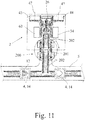
- the laying head 26 now works as follows: After a section of a fiber web has been laid on a workpiece 12, the fiber strands 13 are severed by the cutting device 119 and a front end of the fiber strands 13 is located in the region of the cutting device. The laying head 26 is moved as close as possible to a last spatially fixed deflection 56 of the fiber supply unit 42 in the course of a laying stroke in the laying direction. The laying head 26 is then lifted off the workpiece by a small stroke in the z-direction so that the compacting roller 109 no longer touches the workpiece 12.
- the fiber strands 13 to be laid are then clamped in the clamping device 111 of the laying head 26.
- the laying head 26 is then moved relative to the fiber supply unit 42 in the y-direction by one laying stroke into a starting position. Because of the clamping, the fibers are pulled out of the fiber supply unit 42 by the laying stroke.
- the laying head 26 is then moved again a little in the direction of a last deflection 56 of the fiber supply unit, the pre-conveyor roller 115 driving the fibers until the fiber web arrives at the compacting roller 109.
- the pre-conveyor roller 115 driving the fibers until the fiber web arrives at the compacting roller 109.
- no fibers are drawn from the fiber supply unit 42.
- the pinch roller can still remain in the clamped state, since it has a free-wheeling function in the conveying direction of the fibers.
- the clamping device is then released.
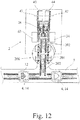
- the laying head 26 is previously or subsequently lowered onto the workpiece 12 and is thus in a starting position for laying the fiber web.
- the workpiece may have been moved to a changed position or orientation in the meantime.
- the laying head 26 is moved from the starting position to an end position with the fibers 13 being laid on the workpiece 12. Since the fiber strands 13 have previously been pulled out of the fiber supply unit 42, no fibers 13 are drawn from the fiber supply unit 42 while the fibers are being deposited on the workpiece 12.
- inventive pulling of the fibers by the laying stroke can be implemented independently of a positioning of the bobbin bearings 43, 44.
- the extension around the laying stroke is carried out by the movement of the laying head relative to a last spatially fixed deflection of the fiber supply unit 42. Accordingly, the positioning of the bobbin hunters 43, 44 in particular relative to the laying head 26 is largely freely selectable.
Landscapes
- Engineering & Computer Science (AREA)
- Chemical & Material Sciences (AREA)
- Composite Materials (AREA)
- Mechanical Engineering (AREA)
- Robotics (AREA)
- Nonwoven Fabrics (AREA)
- Moulding By Coating Moulds (AREA)
- Lining Or Joining Of Plastics Or The Like (AREA)
- Reinforced Plastic Materials (AREA)
Claims (16)
- Machine à poser des fibres (2) destinée à produire des structures de fibres, comprenant
un plateau porte-outil (23) permettant d'amener une pièce à travailler (12) dans une direction d'amenée (x) ;
une tête de pose (26) pour appliquer des fibres (13) sur la pièce à travailler (12) ; et
une unité de fourniture de fibres (42) pour amener plusieurs brins de fibres (13) à la tête de pose (26) ;
les plusieurs brins de fibres (13) étant assemblés à la tête de pose (26) en une nappe de fibres à appliquer sur la pièce à travailler (12) ;
la tête de pose (26) étant mobile par rapport à l'unité de fourniture de fibres (42) dans une direction de pose (y),
un dispositif de serrage (111) pour un serrage amovible des brins de fibres (13) étant disposé à la tête de pose (26),
dans laquelle une pose d'une partie de la nappe de fibres (13) sur la pièce à travailler (12) est effectuée une fois que les brins de fibres (13) ont été avancés sur une course de pose au moyen de la tête de pose (26) de sorte que pendant l'application des fibres (13) sur la pièce à travailler (12) aucune fibre (13) n'est extraite de l'unité de fourniture de fibres (42). - Machine à poser des fibres selon la revendication 1, caractérisée en ce que l'unité de fourniture de fibres (42) est disposée de manière stationnaire, en particulier la tête de pose (26) ne pouvant être déplacée que dans exactement un plan par rapport à l'unité de fourniture de fibres (42).
- Machine à poser des fibres selon l'une quelconque des revendications précédentes, caractérisée en ce que le dispositif de serrage (111) est desserré pendant la pose de la partie de la nappe de fibres (13).
- Machine à poser des fibres selon l'une quelconque des revendications précédentes, caractérisée en ce que le dispositif de serrage (111) comprend au moins un rouleau de serrage, en particulier deux rouleaux de serrage (112, 113) coopérant l'un avec l'autre.
- Machine à poser des fibres selon l'une quelconque des revendications précédentes, caractérisée en ce que la tête de pose (26) comprend deux dispositifs d'amenée (101, 102) s'étendant selon un angle l'un par rapport à l'autre, un premier des dispositifs d'amenée (101) guidant un premier groupe de brins de fibres (13) et le deuxième des dispositifs d'amenée (102) guidant un deuxième groupe de brins de fibres (13) dans une zone d'intersection (103) pour assembler les deux groupes de brins de fibres (13) afin de créer la nappe de fibres.
- Machine à poser des fibres selon l'une quelconque des revendications précédentes, caractérisée en ce que les fibres (13) peuvent être sectionnées au moyen d'un dispositif de coupe (119) disposé au niveau de la tête de pose (26), le dispositif de coupe (119) comprenant une pluralité d'éléments coupants (120) pouvant être commandés séparément et qui peuvent séparer différentes parties des fibres (13) transversalement à la direction de pose.
- Machine à poser des fibres selon la revendication 6, caractérisée en ce que le dispositif de coupe (119) comprend un élément actionneur (121) pour actionner au moins l'un des éléments coupants (120), l'élément actionneur (121) étant réalisé séparément de l'élément coupant (120) et en particulier sur une partie supérieure (105, 106), amovible à des fins de maintenance, de la tête de pose (26).
- Machine à poser des fibres selon l'une quelconque des revendications précédentes, caractérisée en ce qu'au niveau de la tête de pose (26), au moins un rouleau de transport d'avance (115) est prévu pour une avance entraînée, le rouleau de transport d'avance (115) étant disposé entre le dispositif de serrage (111) et un rouleau de compactage (109) côté sortie de la tête de pose (26).
- Machine à poser des fibres selon l'une quelconque des revendications précédentes, caractérisée en ce que la machine à poser des fibres (2) est entièrement installée sur un bâti de machine (15).
- Machine à poser des fibres selon l'une quelconque des revendications précédentes, caractérisée en ce que la machine à poser des fibres (2) comprend un boîtier (58) fermé climatiquement.
- Machine à poser des fibres selon l'une quelconque des revendications précédentes, caractérisée en ce que la pièce à travailler (12) est disposée sur une palette (14) transportable automatiquement.
- Machine à poser des fibres selon la revendication 11, caractérisée en ce qu'une surface de la palette (14) portant la pièce à travailler (12) est inclinée selon un angle de moins de 30 degrés par rapport à la verticale.
- Machine à poser des fibres selon la revendication 12, caractérisée en ce que la direction de pose s'étend dans un plan qui est incliné de moins de 30 degrés par rapport à la verticale.
- Machine à poser des fibres selon l'une quelconque des revendications précédentes, caractérisée en ce que les brins de fibres (13) respectifs sont enroulés sur des bobines (46) échangeables, les bobines (46) étant placées sur des axes de rotation (47) entraînés dans le sens inverse d'une direction de déroulement, les entraînements des axes de rotation (47) présentant une limitation de couple.
- Procédé permettant de poser une nappe de fibres sur une pièce à travailler (12), en particulier au moyen d'un dispositif selon l'une quelconque des revendications précédentes, comprenant les étapes consistant à :a. serrer les fibres (13) à poser dans un dispositif de serrage (111) d'une tête de pose (26) ;b. déplacer la tête de pose (26) par rapport à une unité de fourniture de fibres (42) dans une position initiale, les fibres (13) étant extraites de l'unité de fourniture de fibres (42) sur une course de pose ;c. desserrer le dispositif de serrage (111) ;d. déplacer la tête de pose (26) de la position initiale à une position finale en posant les fibres (13) sur la pièce à travailler (12), de sorte que pendant l'application des fibres (13) sur la pièce à travailler (12) aucune fibre (13) n'est extraite de l'unité de fourniture de fibres (42).
- Procédé selon la revendication 15, caractérisée en ce qu'après l'étape c) les fibres (13) sont déplacées au moyen d'un rouleau de transport d'avance (115) entraîné par rapport à la tête de pose (26), les fibres (13) n'étant en particulier pas extraites de l'unité de fourniture de fibres (42) au moyen du rouleau de transport d'avance (115).
Applications Claiming Priority (2)
| Application Number | Priority Date | Filing Date | Title |
|---|---|---|---|
| DE102015002777.8A DE102015002777A1 (de) | 2015-03-06 | 2015-03-06 | Faserlegemaschine |
| PCT/EP2016/054678 WO2016142297A2 (fr) | 2015-03-06 | 2016-03-04 | Poseuse de fibres |
Publications (2)
| Publication Number | Publication Date |
|---|---|
| EP3291973A2 EP3291973A2 (fr) | 2018-03-14 |
| EP3291973B1 true EP3291973B1 (fr) | 2020-08-12 |
Family
ID=55486650
Family Applications (1)
| Application Number | Title | Priority Date | Filing Date |
|---|---|---|---|
| EP16708641.2A Active EP3291973B1 (fr) | 2015-03-06 | 2016-03-04 | Dispositif de depose de fibres et procede pour deposer une gerbe de fibres sur une piece |
Country Status (9)
| Country | Link |
|---|---|
| US (1) | US10603849B2 (fr) |
| EP (1) | EP3291973B1 (fr) |
| JP (1) | JP6820860B2 (fr) |
| KR (1) | KR102414066B1 (fr) |
| CN (1) | CN107530987B (fr) |
| DE (1) | DE102015002777A1 (fr) |
| ES (1) | ES2821000T3 (fr) |
| RU (1) | RU2714068C2 (fr) |
| WO (1) | WO2016142297A2 (fr) |
Families Citing this family (14)
| Publication number | Priority date | Publication date | Assignee | Title |
|---|---|---|---|---|
| DE102015002775A1 (de) | 2015-03-06 | 2016-09-08 | Brötje-Automation GmbH | System zur Fertigung von Faser-Verbundbauteilen |
| DE102015002777A1 (de) | 2015-03-06 | 2016-09-08 | Broetje-Automation Gmbh | Faserlegemaschine |
| DE102016123505A1 (de) * | 2016-12-05 | 2018-06-07 | Institut Für Verbundwerkstoffe Gmbh | Vorrichtung und Verfahren zur Ablage von imprägnierten Fasern |
| DE202017106345U1 (de) * | 2017-10-19 | 2019-01-25 | Broetje-Automation Gmbh | Endeffektor |
| CN108582814B (zh) * | 2018-05-25 | 2023-11-03 | 中国科学院自动化研究所 | 单驱动的复合材料铺丝头一体化装置及其重送轮轴系统 |
| CN113840718B (zh) * | 2019-06-14 | 2024-10-22 | 法孚机械加工系统股份有限公司 | 模块化纤维放置头 |
| CN110394997B (zh) * | 2019-07-31 | 2020-06-30 | 南京航空航天大学 | 一种环框复合材料制件铺丝装备及工作方法 |
| CN111300803A (zh) * | 2020-03-27 | 2020-06-19 | 四川德源石油天然气工程有限公司 | 一种管道、缠绕耐磨保护层安装装置及安装方法 |
| US11986917B2 (en) * | 2020-11-18 | 2024-05-21 | The Boeing Company | Indexing apparatus and method of indexing |
| DE102021111900A1 (de) | 2021-05-06 | 2022-11-10 | Technische Universität Chemnitz, Körperschaft des öffentlichen Rechts | Legevorrichtung und Legeverfahren für bandförmiges Material |
| CN113799413A (zh) * | 2021-09-08 | 2021-12-17 | 常州佰承复合材料有限公司 | 一种玻纤布铺层车以及控制玻纤布张力大小的方法 |
| CN114347459B (zh) * | 2021-12-30 | 2024-08-02 | 中国航空工业集团公司北京长城计量测试技术研究所 | 一种基于3d打印的旋转式光纤铺设装置及方法 |
| FR3131706B1 (fr) * | 2022-01-12 | 2024-08-23 | Safran | Tête d’application pour le placement automatique de fibres |
| CN117719961B (zh) * | 2024-02-03 | 2024-04-12 | 张家港市科兴炭纤维制品有限公司 | 自动布线装置 |
Family Cites Families (24)
| Publication number | Priority date | Publication date | Assignee | Title |
|---|---|---|---|---|
| US3574040A (en) * | 1967-06-29 | 1971-04-06 | Gen Dynamics Corp | Apparatus for making laminated structural shapes by the controlled detrusive placement and polymerization of tectonic filamentous tapes |
| US5110395A (en) * | 1989-12-04 | 1992-05-05 | Cincinnati Milacron Inc. | Fiber placement head |
| FR2686080B1 (fr) * | 1992-01-14 | 1994-11-10 | Aerospatiale | Procede de depose au contact a chaud de materiau composite fibre a matrice vitreuse et dispositif pour la mise en óoeuvre du procede. |
| GB9510046D0 (en) * | 1995-05-18 | 1995-07-12 | Ecole Polytechnique Fudurale D | Process for the manufacture of polymer and composite materials and related equipment |
| AU1360199A (en) * | 1997-11-05 | 1999-05-24 | Sikorsky Aircraft Corporation | Feed control system for fiber placement machines |
| US7208219B2 (en) * | 1997-12-18 | 2007-04-24 | Lrm Industries, Llc | Thermoplastic molding process and apparatus |
| FR2785623B1 (fr) * | 1998-11-10 | 2001-01-26 | Aerospatiale | Procede et dispositif de depose au contact de fils de fibres pre-impregnees notamment pour la realisation de structures complexes en materiau composite polymerise par ionisation |
| DE10005202B4 (de) * | 2000-02-03 | 2007-03-01 | Institut Für Verbundwerkstoffe Gmbh | Verfahren und Vorrichtung zur kontinuierlichen bauteil- und prozessorientierten Herstellung von Verstärkungsstruktur-Halbzeugen für Faser-Kunststoff-Verbundwerkstoffe |
| US7527222B2 (en) * | 2004-04-06 | 2009-05-05 | The Boeing Company | Composite barrel sections for aircraft fuselages and other structures, and methods and systems for manufacturing such barrel sections |
| US7836931B2 (en) * | 2004-06-22 | 2010-11-23 | Slyne William J | Tape laying apparatus and method |
| FR2913365B1 (fr) * | 2007-03-06 | 2013-07-26 | Coriolis Composites Attn Olivier Bouroullec | Tete d'application de fibres avec systemes de coupe de fibres particuliers |
| DE102007037072B4 (de) | 2007-08-06 | 2017-12-21 | Bayerische Motoren Werke Aktiengesellschaft | Hochflexible Schäumzelle |
| US8048253B2 (en) | 2007-09-26 | 2011-11-01 | Fiberforge Corporation | System and method for the rapid, automated creation of advanced composite tailored blanks |
| US8752293B2 (en) * | 2007-12-07 | 2014-06-17 | The Boeing Company | Method of fabricating structures using composite modules and structures made thereby |
| EP2230070A1 (fr) * | 2009-03-06 | 2010-09-22 | Lm Glasfiber A/S | Procédé et ligne de fabrication pour fabriquer des pales d'éoliennes |
| FR2950285A1 (fr) * | 2009-09-21 | 2011-03-25 | Airbus Operations Sas | Dispositif de drapage automatise |
| DE102010013131A1 (de) * | 2009-12-21 | 2011-06-22 | REHAU AG + Co., 95111 | Verfahren zur Herstellung von endlosfaserverstärkten Formteilen aus thermoplastischem Kunststoff sowie Kraftfahrzeugformteil |
| DE102010015199B9 (de) * | 2010-04-16 | 2013-08-01 | Compositence Gmbh | Faserführungsvorrichtung und Vorrichtung zum Aufbau eines dreidimensionalen Vorformlings |
| US9193140B2 (en) * | 2013-03-15 | 2015-11-24 | Composite Technology & Applications Limited | Composite material lay-up equipment |
| DK3045297T3 (en) | 2013-05-31 | 2018-04-09 | Lm Wind Power Int Tech Ii Aps | Mold and method of assisting in the manufacture of a wind turbine blade shell |
| FR3006938B1 (fr) * | 2013-06-18 | 2015-10-02 | Coriolis Composites | Tete d application de fibres bi directionnelle a deux rouleaux |
| US9481158B2 (en) * | 2013-07-11 | 2016-11-01 | The Boeing Company | Short course fiber placement head |
| DE102015002777A1 (de) | 2015-03-06 | 2016-09-08 | Broetje-Automation Gmbh | Faserlegemaschine |
| DE102015002775A1 (de) | 2015-03-06 | 2016-09-08 | Brötje-Automation GmbH | System zur Fertigung von Faser-Verbundbauteilen |
-
2015
- 2015-03-06 DE DE102015002777.8A patent/DE102015002777A1/de not_active Withdrawn
-
2016
- 2016-03-04 CN CN201680014089.4A patent/CN107530987B/zh active Active
- 2016-03-04 US US15/556,226 patent/US10603849B2/en active Active
- 2016-03-04 WO PCT/EP2016/054678 patent/WO2016142297A2/fr not_active Ceased
- 2016-03-04 ES ES16708641T patent/ES2821000T3/es active Active
- 2016-03-04 EP EP16708641.2A patent/EP3291973B1/fr active Active
- 2016-03-04 KR KR1020177028020A patent/KR102414066B1/ko active Active
- 2016-03-04 JP JP2017546937A patent/JP6820860B2/ja active Active
- 2016-03-04 RU RU2017134384A patent/RU2714068C2/ru active
Non-Patent Citations (1)
| Title |
|---|
| None * |
Also Published As
| Publication number | Publication date |
|---|---|
| WO2016142297A3 (fr) | 2016-11-10 |
| CN107530987B (zh) | 2020-04-24 |
| ES2821000T3 (es) | 2021-04-23 |
| US10603849B2 (en) | 2020-03-31 |
| US20180036968A1 (en) | 2018-02-08 |
| RU2017134384A (ru) | 2019-04-05 |
| EP3291973A2 (fr) | 2018-03-14 |
| CN107530987A (zh) | 2018-01-02 |
| DE102015002777A1 (de) | 2016-09-08 |
| WO2016142297A2 (fr) | 2016-09-15 |
| RU2017134384A3 (fr) | 2019-04-15 |
| JP2018512303A (ja) | 2018-05-17 |
| KR20180016337A (ko) | 2018-02-14 |
| RU2714068C2 (ru) | 2020-02-11 |
| KR102414066B1 (ko) | 2022-06-27 |
| JP6820860B2 (ja) | 2021-01-27 |
Similar Documents
| Publication | Publication Date | Title |
|---|---|---|
| EP3291973B1 (fr) | Dispositif de depose de fibres et procede pour deposer une gerbe de fibres sur une piece | |
| EP3096930B1 (fr) | Machine de placement de fibres et procédé de production de nappes de fibres | |
| EP3265296A2 (fr) | Système de fabrication de structures composites à base de fibres | |
| EP3377308B1 (fr) | Installation de fabrication pour poser des bandes de fibres | |
| EP2136979B1 (fr) | Tampon elastique d'application de fibres, dispositif d'application comprenant un tel tampon et utilisation de ce dispositif | |
| EP2694262B1 (fr) | Dispositif et procédé de fabrication de préformes à fibres constituant notamment une phase préalable dans la fabrication de composants plastiques renforcés par fibres | |
| DE102012218178A1 (de) | Vorrichtung zur Herstellung von Faservorformlingen, die insbesondere eine Vorstufe bei der Herstellung von faserverstärkten Kunststoffbauteilen darstellen | |
| WO2018073359A1 (fr) | Dispositif et procédé de pose de bande permettant une pose flexible et rapide de bandes de différentes largeurs | |
| DE102008052670B4 (de) | Flechtvorrichtung und Flechtverfahren zum Beflechten eines Flechtkerns | |
| EP0800449B1 (fr) | Procede et dispositif pour la fabrication d'inserts de renforcement pour des composites de materiaux, en particulier pour meules d'affutage ou de tronconnage | |
| EP3814121B1 (fr) | Procédé et dispositif de production de pièces comportant un matériau composite renforcé de fibres | |
| DE9010098U1 (de) | Vorrichtung zum Bestücken der Spulendorne eines Spulengatters | |
| EP3509829B1 (fr) | Dispositif de pose de bandes et procédé de pose de bandes permettant la pose d'une bande à une distance variable | |
| EP4086068B1 (fr) | Dispositif de pose et procédé de pose pour matières en forme de bande | |
| DE202016104945U1 (de) | Tapelegevorrichtung zum simultanen Legen von Tapes mit variablem Abstand | |
| DE202021102470U1 (de) | Legevorrichtung für bandförmiges Material | |
| DE9010089U1 (de) | Vorrichtung zum Entfernen von Spulenhülsen von den Spulendornen eines Spulengatters o.dgl. | |
| DE202016104965U1 (de) | Tapelegevorrichtung |
Legal Events
| Date | Code | Title | Description |
|---|---|---|---|
| STAA | Information on the status of an ep patent application or granted ep patent |
Free format text: STATUS: THE INTERNATIONAL PUBLICATION HAS BEEN MADE |
|
| PUAI | Public reference made under article 153(3) epc to a published international application that has entered the european phase |
Free format text: ORIGINAL CODE: 0009012 |
|
| STAA | Information on the status of an ep patent application or granted ep patent |
Free format text: STATUS: REQUEST FOR EXAMINATION WAS MADE |
|
| 17P | Request for examination filed |
Effective date: 20170831 |
|
| AK | Designated contracting states |
Kind code of ref document: A2 Designated state(s): AL AT BE BG CH CY CZ DE DK EE ES FI FR GB GR HR HU IE IS IT LI LT LU LV MC MK MT NL NO PL PT RO RS SE SI SK SM TR |
|
| AX | Request for extension of the european patent |
Extension state: BA ME |
|
| DAV | Request for validation of the european patent (deleted) | ||
| DAX | Request for extension of the european patent (deleted) | ||
| STAA | Information on the status of an ep patent application or granted ep patent |
Free format text: STATUS: EXAMINATION IS IN PROGRESS |
|
| 17Q | First examination report despatched |
Effective date: 20190708 |
|
| GRAP | Despatch of communication of intention to grant a patent |
Free format text: ORIGINAL CODE: EPIDOSNIGR1 |
|
| STAA | Information on the status of an ep patent application or granted ep patent |
Free format text: STATUS: GRANT OF PATENT IS INTENDED |
|
| INTG | Intention to grant announced |
Effective date: 20200406 |
|
| GRAS | Grant fee paid |
Free format text: ORIGINAL CODE: EPIDOSNIGR3 |
|
| GRAA | (expected) grant |
Free format text: ORIGINAL CODE: 0009210 |
|
| STAA | Information on the status of an ep patent application or granted ep patent |
Free format text: STATUS: THE PATENT HAS BEEN GRANTED |
|
| AK | Designated contracting states |
Kind code of ref document: B1 Designated state(s): AL AT BE BG CH CY CZ DE DK EE ES FI FR GB GR HR HU IE IS IT LI LT LU LV MC MK MT NL NO PL PT RO RS SE SI SK SM TR |
|
| REG | Reference to a national code |
Ref country code: CH Ref legal event code: EP |
|
| REG | Reference to a national code |
Ref country code: IE Ref legal event code: FG4D Free format text: LANGUAGE OF EP DOCUMENT: GERMAN |
|
| REG | Reference to a national code |
Ref country code: DE Ref legal event code: R096 Ref document number: 502016010831 Country of ref document: DE |
|
| REG | Reference to a national code |
Ref country code: AT Ref legal event code: REF Ref document number: 1301141 Country of ref document: AT Kind code of ref document: T Effective date: 20200915 |
|
| REG | Reference to a national code |
Ref country code: LT Ref legal event code: MG4D |
|
| REG | Reference to a national code |
Ref country code: NL Ref legal event code: MP Effective date: 20200812 |
|
| PG25 | Lapsed in a contracting state [announced via postgrant information from national office to epo] |
Ref country code: GR Free format text: LAPSE BECAUSE OF FAILURE TO SUBMIT A TRANSLATION OF THE DESCRIPTION OR TO PAY THE FEE WITHIN THE PRESCRIBED TIME-LIMIT Effective date: 20201113 Ref country code: BG Free format text: LAPSE BECAUSE OF FAILURE TO SUBMIT A TRANSLATION OF THE DESCRIPTION OR TO PAY THE FEE WITHIN THE PRESCRIBED TIME-LIMIT Effective date: 20201112 Ref country code: NO Free format text: LAPSE BECAUSE OF FAILURE TO SUBMIT A TRANSLATION OF THE DESCRIPTION OR TO PAY THE FEE WITHIN THE PRESCRIBED TIME-LIMIT Effective date: 20201112 Ref country code: LT Free format text: LAPSE BECAUSE OF FAILURE TO SUBMIT A TRANSLATION OF THE DESCRIPTION OR TO PAY THE FEE WITHIN THE PRESCRIBED TIME-LIMIT Effective date: 20200812 Ref country code: FI Free format text: LAPSE BECAUSE OF FAILURE TO SUBMIT A TRANSLATION OF THE DESCRIPTION OR TO PAY THE FEE WITHIN THE PRESCRIBED TIME-LIMIT Effective date: 20200812 Ref country code: SE Free format text: LAPSE BECAUSE OF FAILURE TO SUBMIT A TRANSLATION OF THE DESCRIPTION OR TO PAY THE FEE WITHIN THE PRESCRIBED TIME-LIMIT Effective date: 20200812 Ref country code: HR Free format text: LAPSE BECAUSE OF FAILURE TO SUBMIT A TRANSLATION OF THE DESCRIPTION OR TO PAY THE FEE WITHIN THE PRESCRIBED TIME-LIMIT Effective date: 20200812 |
|
| PG25 | Lapsed in a contracting state [announced via postgrant information from national office to epo] |
Ref country code: LV Free format text: LAPSE BECAUSE OF FAILURE TO SUBMIT A TRANSLATION OF THE DESCRIPTION OR TO PAY THE FEE WITHIN THE PRESCRIBED TIME-LIMIT Effective date: 20200812 Ref country code: PL Free format text: LAPSE BECAUSE OF FAILURE TO SUBMIT A TRANSLATION OF THE DESCRIPTION OR TO PAY THE FEE WITHIN THE PRESCRIBED TIME-LIMIT Effective date: 20200812 Ref country code: RS Free format text: LAPSE BECAUSE OF FAILURE TO SUBMIT A TRANSLATION OF THE DESCRIPTION OR TO PAY THE FEE WITHIN THE PRESCRIBED TIME-LIMIT Effective date: 20200812 Ref country code: NL Free format text: LAPSE BECAUSE OF FAILURE TO SUBMIT A TRANSLATION OF THE DESCRIPTION OR TO PAY THE FEE WITHIN THE PRESCRIBED TIME-LIMIT Effective date: 20200812 Ref country code: IS Free format text: LAPSE BECAUSE OF FAILURE TO SUBMIT A TRANSLATION OF THE DESCRIPTION OR TO PAY THE FEE WITHIN THE PRESCRIBED TIME-LIMIT Effective date: 20201212 |
|
| REG | Reference to a national code |
Ref country code: ES Ref legal event code: FG2A Ref document number: 2821000 Country of ref document: ES Kind code of ref document: T3 Effective date: 20210423 |
|
| PG25 | Lapsed in a contracting state [announced via postgrant information from national office to epo] |
Ref country code: DK Free format text: LAPSE BECAUSE OF FAILURE TO SUBMIT A TRANSLATION OF THE DESCRIPTION OR TO PAY THE FEE WITHIN THE PRESCRIBED TIME-LIMIT Effective date: 20200812 Ref country code: CZ Free format text: LAPSE BECAUSE OF FAILURE TO SUBMIT A TRANSLATION OF THE DESCRIPTION OR TO PAY THE FEE WITHIN THE PRESCRIBED TIME-LIMIT Effective date: 20200812 Ref country code: SM Free format text: LAPSE BECAUSE OF FAILURE TO SUBMIT A TRANSLATION OF THE DESCRIPTION OR TO PAY THE FEE WITHIN THE PRESCRIBED TIME-LIMIT Effective date: 20200812 Ref country code: RO Free format text: LAPSE BECAUSE OF FAILURE TO SUBMIT A TRANSLATION OF THE DESCRIPTION OR TO PAY THE FEE WITHIN THE PRESCRIBED TIME-LIMIT Effective date: 20200812 Ref country code: EE Free format text: LAPSE BECAUSE OF FAILURE TO SUBMIT A TRANSLATION OF THE DESCRIPTION OR TO PAY THE FEE WITHIN THE PRESCRIBED TIME-LIMIT Effective date: 20200812 |
|
| REG | Reference to a national code |
Ref country code: DE Ref legal event code: R097 Ref document number: 502016010831 Country of ref document: DE |
|
| PG25 | Lapsed in a contracting state [announced via postgrant information from national office to epo] |
Ref country code: AL Free format text: LAPSE BECAUSE OF FAILURE TO SUBMIT A TRANSLATION OF THE DESCRIPTION OR TO PAY THE FEE WITHIN THE PRESCRIBED TIME-LIMIT Effective date: 20200812 |
|
| PLBE | No opposition filed within time limit |
Free format text: ORIGINAL CODE: 0009261 |
|
| STAA | Information on the status of an ep patent application or granted ep patent |
Free format text: STATUS: NO OPPOSITION FILED WITHIN TIME LIMIT |
|
| PG25 | Lapsed in a contracting state [announced via postgrant information from national office to epo] |
Ref country code: SK Free format text: LAPSE BECAUSE OF FAILURE TO SUBMIT A TRANSLATION OF THE DESCRIPTION OR TO PAY THE FEE WITHIN THE PRESCRIBED TIME-LIMIT Effective date: 20200812 |
|
| 26N | No opposition filed |
Effective date: 20210514 |
|
| PG25 | Lapsed in a contracting state [announced via postgrant information from national office to epo] |
Ref country code: SI Free format text: LAPSE BECAUSE OF FAILURE TO SUBMIT A TRANSLATION OF THE DESCRIPTION OR TO PAY THE FEE WITHIN THE PRESCRIBED TIME-LIMIT Effective date: 20200812 |
|
| PG25 | Lapsed in a contracting state [announced via postgrant information from national office to epo] |
Ref country code: MC Free format text: LAPSE BECAUSE OF FAILURE TO SUBMIT A TRANSLATION OF THE DESCRIPTION OR TO PAY THE FEE WITHIN THE PRESCRIBED TIME-LIMIT Effective date: 20200812 |
|
| REG | Reference to a national code |
Ref country code: CH Ref legal event code: PL |
|
| REG | Reference to a national code |
Ref country code: BE Ref legal event code: MM Effective date: 20210331 |
|
| PG25 | Lapsed in a contracting state [announced via postgrant information from national office to epo] |
Ref country code: CH Free format text: LAPSE BECAUSE OF NON-PAYMENT OF DUE FEES Effective date: 20210331 Ref country code: LU Free format text: LAPSE BECAUSE OF NON-PAYMENT OF DUE FEES Effective date: 20210304 Ref country code: LI Free format text: LAPSE BECAUSE OF NON-PAYMENT OF DUE FEES Effective date: 20210331 Ref country code: IE Free format text: LAPSE BECAUSE OF NON-PAYMENT OF DUE FEES Effective date: 20210304 |
|
| REG | Reference to a national code |
Ref country code: AT Ref legal event code: MM01 Ref document number: 1301141 Country of ref document: AT Kind code of ref document: T Effective date: 20210304 |
|
| PG25 | Lapsed in a contracting state [announced via postgrant information from national office to epo] |
Ref country code: BE Free format text: LAPSE BECAUSE OF NON-PAYMENT OF DUE FEES Effective date: 20210331 |
|
| PG25 | Lapsed in a contracting state [announced via postgrant information from national office to epo] |
Ref country code: AT Free format text: LAPSE BECAUSE OF NON-PAYMENT OF DUE FEES Effective date: 20210304 |
|
| PG25 | Lapsed in a contracting state [announced via postgrant information from national office to epo] |
Ref country code: PT Free format text: LAPSE BECAUSE OF FAILURE TO SUBMIT A TRANSLATION OF THE DESCRIPTION OR TO PAY THE FEE WITHIN THE PRESCRIBED TIME-LIMIT Effective date: 20201214 |
|
| PG25 | Lapsed in a contracting state [announced via postgrant information from national office to epo] |
Ref country code: CY Free format text: LAPSE BECAUSE OF FAILURE TO SUBMIT A TRANSLATION OF THE DESCRIPTION OR TO PAY THE FEE WITHIN THE PRESCRIBED TIME-LIMIT Effective date: 20200812 |
|
| PG25 | Lapsed in a contracting state [announced via postgrant information from national office to epo] |
Ref country code: HU Free format text: LAPSE BECAUSE OF FAILURE TO SUBMIT A TRANSLATION OF THE DESCRIPTION OR TO PAY THE FEE WITHIN THE PRESCRIBED TIME-LIMIT; INVALID AB INITIO Effective date: 20160304 |
|
| PG25 | Lapsed in a contracting state [announced via postgrant information from national office to epo] |
Ref country code: MK Free format text: LAPSE BECAUSE OF FAILURE TO SUBMIT A TRANSLATION OF THE DESCRIPTION OR TO PAY THE FEE WITHIN THE PRESCRIBED TIME-LIMIT Effective date: 20200812 |
|
| PG25 | Lapsed in a contracting state [announced via postgrant information from national office to epo] |
Ref country code: MT Free format text: LAPSE BECAUSE OF FAILURE TO SUBMIT A TRANSLATION OF THE DESCRIPTION OR TO PAY THE FEE WITHIN THE PRESCRIBED TIME-LIMIT Effective date: 20200812 |
|
| PGFP | Annual fee paid to national office [announced via postgrant information from national office to epo] |
Ref country code: DE Payment date: 20250327 Year of fee payment: 10 |
|
| PGFP | Annual fee paid to national office [announced via postgrant information from national office to epo] |
Ref country code: ES Payment date: 20250429 Year of fee payment: 10 |
|
| PGFP | Annual fee paid to national office [announced via postgrant information from national office to epo] |
Ref country code: GB Payment date: 20260324 Year of fee payment: 11 |
|
| PGFP | Annual fee paid to national office [announced via postgrant information from national office to epo] |
Ref country code: IT Payment date: 20260324 Year of fee payment: 11 |
|
| PGFP | Annual fee paid to national office [announced via postgrant information from national office to epo] |
Ref country code: FR Payment date: 20260320 Year of fee payment: 11 |
|
| PGFP | Annual fee paid to national office [announced via postgrant information from national office to epo] |
Ref country code: TR Payment date: 20260226 Year of fee payment: 11 |