EP3291999B1 - Sicherheitsmerkmal und verfahren zu dessen herstellung - Google Patents
Sicherheitsmerkmal und verfahren zu dessen herstellung Download PDFInfo
- Publication number
- EP3291999B1 EP3291999B1 EP16716165.2A EP16716165A EP3291999B1 EP 3291999 B1 EP3291999 B1 EP 3291999B1 EP 16716165 A EP16716165 A EP 16716165A EP 3291999 B1 EP3291999 B1 EP 3291999B1
- Authority
- EP
- European Patent Office
- Prior art keywords
- holes
- substrate
- area
- security
- rim
- Prior art date
- Legal status (The legal status is an assumption and is not a legal conclusion. Google has not performed a legal analysis and makes no representation as to the accuracy of the status listed.)
- Active
Links
Images





Classifications
-
- B—PERFORMING OPERATIONS; TRANSPORTING
- B42—BOOKBINDING; ALBUMS; FILES; SPECIAL PRINTED MATTER
- B42D—BOOKS; BOOK COVERS; LOOSE LEAVES; PRINTED MATTER CHARACTERISED BY IDENTIFICATION OR SECURITY FEATURES; PRINTED MATTER OF SPECIAL FORMAT OR STYLE NOT OTHERWISE PROVIDED FOR; DEVICES FOR USE THEREWITH AND NOT OTHERWISE PROVIDED FOR; MOVABLE-STRIP WRITING OR READING APPARATUS
- B42D25/00—Information-bearing cards or sheet-like structures characterised by identification or security features; Manufacture thereof
- B42D25/40—Manufacture
- B42D25/405—Marking
- B42D25/41—Marking using electromagnetic radiation
-
- B—PERFORMING OPERATIONS; TRANSPORTING
- B42—BOOKBINDING; ALBUMS; FILES; SPECIAL PRINTED MATTER
- B42D—BOOKS; BOOK COVERS; LOOSE LEAVES; PRINTED MATTER CHARACTERISED BY IDENTIFICATION OR SECURITY FEATURES; PRINTED MATTER OF SPECIAL FORMAT OR STYLE NOT OTHERWISE PROVIDED FOR; DEVICES FOR USE THEREWITH AND NOT OTHERWISE PROVIDED FOR; MOVABLE-STRIP WRITING OR READING APPARATUS
- B42D25/00—Information-bearing cards or sheet-like structures characterised by identification or security features; Manufacture thereof
- B42D25/30—Identification or security features, e.g. for preventing forgery
- B42D25/346—Perforations
-
- B—PERFORMING OPERATIONS; TRANSPORTING
- B42—BOOKBINDING; ALBUMS; FILES; SPECIAL PRINTED MATTER
- B42D—BOOKS; BOOK COVERS; LOOSE LEAVES; PRINTED MATTER CHARACTERISED BY IDENTIFICATION OR SECURITY FEATURES; PRINTED MATTER OF SPECIAL FORMAT OR STYLE NOT OTHERWISE PROVIDED FOR; DEVICES FOR USE THEREWITH AND NOT OTHERWISE PROVIDED FOR; MOVABLE-STRIP WRITING OR READING APPARATUS
- B42D25/00—Information-bearing cards or sheet-like structures characterised by identification or security features; Manufacture thereof
- B42D25/40—Manufacture
- B42D25/405—Marking
- B42D25/43—Marking by removal of material
- B42D25/435—Marking by removal of material using electromagnetic radiation, e.g. laser
Definitions
- the invention relates to a method for producing a security feature for a security element, a security paper or a data carrier having a carrier, wherein the carrier is modifiable by laser radiation in terms of its color, introduced by the action of laser beam in the beam cross-section intensity laser holes of certain hole diameter in the carrier be having an edge, wherein at the same time due to the intensity distribution over the beam cross section in a zone surrounding the edge of certain zone width of the carrier is modified by the laser radiation, so that the edge is colored.
- the invention further relates to a security feature for a security element, a security paper or a data carrier, which has a carrier that is modifiable in color, in the carrier holes of certain hole diameter are introduced, which have an edge, and in a surrounding zone of the edge certain zone width of the carrier is modified so that the edge is colored, as well as a security element, a security paper and a document of value or a data carrier with such a security feature.
- Identity cards such as credit cards or identity cards
- the production of continuous openings in value documents, eg banknote papers, by laser cutting has also been known for some time.
- document DE 43 34 848 C1 describes a security with a closed by a transparent cover film window-like opening, which can be generated by a laser cutting process.
- the WO 2009/003587 A1 describes a manufacturing method and a corresponding security feature of the type mentioned, which is produced by a laser cutting process.
- the support of the security feature is provided with a marker that changes its color by the action of laser beams.
- a cutting laser beam is used whose intensity is not uniformly distributed in the radiation cross section, for example Gaussian.
- Such radiation is referred to herein as laser radiation which is intensity-distributed across the beam cross-section, the radiation intensity decreasing towards the edge of the laser beam. This drop in intensity produces an edge at which the support is no longer cut, but a modification of the marking substance takes place with regard to its color effect. In this way, the edge region of the hole produced by laser radiation appears colored.
- a colored border of holes is also from the WO 2009 / 003588A1
- several laser beams of different intensities are required in order to achieve a particularly large and thus well-recognizable color effect.
- Laser radiation-sensitive marking substances are known, for example, from the following publications: EP 1657072 B1 . EP 000002332012 B1 . US 7270919 . US 7485403 . US 7998900 . US 8021820 . US8048608 . US8048605 . US 8083973 . US 8101544 . US 8101545 . US 8105506 . US 8173253 . US 8178277 . US 8278243 . US 8278244 and US 842028 ,
- the invention is therefore based on the object, a security element, security paper and data carriers of the type mentioned above To further improve the imitation security and to simplify the manufacturability.
- a method for producing a security feature for a security element, a security paper or a data carrier wherein a carrier is provided, which is modifiable by laser radiation in terms of its color, by the action of laser beam in the beam cross-section laser radiation holes of certain hole diameter in the carrier are introduced, which have an edge, wherein at the same time due to the intensity distribution over the beam cross section in a zone surrounding the edge zone width of the carrier is modified by the laser radiation, so that the edge is colored, the holes are arranged covering a surface and within the Area adjacent holes are arranged in a relation to the hole center hole spacing from each other, which is not greater than 2.5 times the sum of maximum hole diameter and double zone width.
- the object is further achieved by a method for producing a security feature for a security element, a security paper or a data carrier, wherein a carrier is provided, which is modifiable by laser radiation in terms of its color, by the action of laser beam in the beam cross-section intensity-distributed laser holes of certain hole diameter in the Carrier are introduced, which have an edge, wherein at the same time due to the intensity distribution over the beam cross section in a zone surrounding the edge zone width of the carrier is modified by the laser radiation, so that the edge is colored, the holes are arranged covering a surface and within the area the holes make up at least 50% of the size of the area.
- a security feature for a security element, a security paper or a data carrier having a carrier wherein the carrier is modifiable in terms of its color by laser radiation, in the carrier holes of a certain hole diameter are introduced, which have an edge, and in a zone of certain zone width surrounding the edge, the support is modified so that the edge is colored, the holes being arranged overlapping one surface and within the surface all adjacent holes are arranged in a hole center distance spaced from each other which is not larger as 2.5 times the sum of maximum hole diameter and double zone width.
- a security feature for a security element, a security paper or a data carrier having a carrier wherein the carrier is modifiable in terms of its color by laser radiation, in the carrier holes of certain hole diameter are introduced, which have an edge, and in a zone of certain zone width surrounding the edge, the carrier is modified such that the edge is colored, the holes covering one surface and within the surface the holes make up at least 50% of the size of the surface.
- the principle of the invention thus provides to perforate the surface, wherein said geometric specifications are met.
- the perforation makes it possible to structure the surface with respect to an outer or inner boundary.
- the outer boundary of the surface can then be a motif encode.
- recesses can be provided within the surface, in which no perforations are provided, so that an inner boundary is given, which can contribute to the motif.
- the perforated surface is thus at least path-coherent, without inner boundary also simply connected.
- a plurality of surfaces can be provided which, among other things, can also be identical, for example in the form of a plurality of lines, each forming a surface, which lie next to one another.
- adjacent holes refers to the shape of the surface. If the surface has an inner boundary, as it is called by way of example, i. at least one recess, and an outer boundary, the holes lying at the respective boundary are adjacent to the holes lying within the surface, of course not to the area outside the boundary, at which the surface ends inside or outside.
- An area outside the boundary of the area may preferably be provided with a coloration which is similar to that of the hole edges. Then, in plan view, the effect that the boundary of the surface is at least partially not visible, in view when the holes are visible, but clearly emerges.
- the holes can be arranged in particular in a dot matrix.
- Various raster structures are possible, such as hexagonal rasters, rectangular rasters etc.
- holes For surfaces with an inner boundary, it is preferable not to form holes at individual points of the dot matrix, and thus to create the recess and the inner boundary.
- These sites may in a further preferred embodiment be colored in the color of the hole edges, e.g. correspondingly arranged points, and most preferably a motif, encode sign or symbol, which is not or poorly in plan view, but clearly visible in the see through.
- the invention uses a special arrangement of the holes in the perforated surface to those in the WO 2009/003587 A1 to reinforce and emphasize the color effect described.
- the term "color” is not limited to a colorful impression, but may also include black.
- the inventive perforation of the surface creates a colorful impression without a viewer would have to search for a colored hole edge first, which could well be the case with a single hole or a single opening.
- a transparent impression is conveyed.
- the arrangement of the holes such that adjacent holes have a hole spacing that does not exceed a certain level, the colored impression is particularly well perceived in plan view of the surface.
- several holes interact with regard to the colored impression.
- the color effect is achieved in some embodiments by using a support that is directly modifiable with the laser radiation.
- the support is previously provided with a suitable marker, e.g. coated, which is modifiable.
- the indication of the hole spacing as the distance between the hole centers of adjacent holes achieved the feature that the hole spacing related to the hole center is not greater than 2.5 times the sum of hole diameter and double zone width, that the colored zones have a comparatively large proportion of the perforated area. This ensures a particularly good color impression. It increases naturally, the higher the proportion of the color-coded zones on the remaining support surface. Therefore, it is alternatively provided that this proportion is at least 50%, preferably even 75% or 90%.
- the minimum gap exists on the connecting line between the hole centers.
- the perforated surface according to the invention appears colored in plan view due to the color effect, e.g. by the marker modified in the zones around the holes. At the same time, there is also a motive in transmitted light due to the perforation of the surface and the thus changed translucency.
- These two motifs are in perfect register with each other, since they were created by one and the same process, namely the perforation of the surface.
- the perforated surface is larger in the x and y direction than a hole. It is therefore a two-dimensional area in which holes are juxtaposed in both coordinate directions.
- a marker is not relevant to the passport of these two motifs.
- the application or provision of the marking substance and the structure of the perforated surface are combined in such a way that no marking substance is present in individual parts of the surface. In these parts, the holes then have no colored border. In the remaining parts, however, the marker is present and the edges of the holes are colored. This gives another appearance of the security feature that is difficult to imitate. If the marking dye is only provided or printed in certain areas, the colored structure of the motif can only be seen in the reflected light and not in others. This encourages viewing in transmitted light.
- the surface can convey a certain design impression. It is therefore preferred in a development that the surface has a first and at least one second pattern, which differ with respect to the grid structure in which the holes are arranged, and / or the hole diameter and / or the hole spacing.
- the laser-radiation-modifiable carrier or its marking substance is modified by the laser beam when the holes are introduced into the carrier.
- use is made of the fact that the laser beam energy in an outer region of the beam cross-section is sufficient to modify the marking substance in the zone around the edge of the holes. In this way, a perfect registration of openings and laser radiation-modified zone is automatically ensured.
- the carrier If you want to provide the carrier with the marker, it is coated in an advantageous variant of the invention on its surface with the marker, for example by a printing process.
- the marking substance is introduced into the volume of the carrier. Depending on the carrier material, different methods are available.
- the marker can advantageously be mixed with the sheet formation of the paper pulp.
- a further advantageous possibility is to introduce the marking substance into the volume of the paper substrate in a dipping bath or to mix the paper substrate, e.g. in a size press, to impregnate with the marker.
- a carrier may also be laser-irradiated without additional tagging material.
- a blackening by a thermal effect is just one example of this.
- the carrier is formed from a plastic film, e.g. the film may be formed thermoreactive or the marker may already be introduced into the volume of the film during the production of the film or subsequently by an impregnation step.
- thermoreactive colored pigments such as ultramarine blue can be used for this purpose.
- marking substances whose infrared-absorbing properties or their magnetic, electrical or luminescent properties are changed by the action of the laser radiation. Security features with such laser radiation modified hole edges can be particularly for the machine Authenticity test be used. It is also possible to use a combination of different marking substances, for example in order to enable both a visual and a machine authenticity check of the security feature. When using several markers, these can come to lie next to each other as well as in different layers one above the other.
- the modification of the carrier / marker may be erosion or destruction.
- the marker is preferably a metallic coating in this case.
- holes are produced with an oblique cutting edge by the laser cut in the carrier.
- An oblique cutting edge can be ensured, for example, by guiding the laser beam at a predetermined angle to the surface normal of the carrier when producing the openings.
- the size of the edge zone can be set, as will be explained in more detail below.
- laser radiation-modifiable effect pigments are used as the laser-radiation-modifiable marker.
- Such effect pigments are available to the person skilled in the art with different properties, in particular with respect to their body color, the color change under laser radiation, the threshold energy and the required laser radiation wavelength.
- effect pigments which change not only their visible color under laser radiation but their infrared-absorbing, magnetic, electrical or luminescent properties are known to the person skilled in the art.
- the modification of the effect pigments can be done with laser radiation in the ultraviolet, visible or infrared spectral range, for example with a CO 2 laser of a wavelength of 10600 nm.
- a pigment-free laser-radiation-modifiable marker is used.
- Pigment-free marking substances can also be applied to the carrier or introduced into the carrier volume, for example as intaglio or printing ink. With pigment-free marking materials, a coating of high transparency can be produced, into which a permanent and high-contrast marking can be introduced by laser action at high speed.
- Pigment-free marking substances can be modified by laser radiation in the ultraviolet, visible or infrared spectral range, for example with the 10600 nm radiation of a CO 2 laser.
- Specific, non-limiting examples of pigment-free laser-modifiable markers are in the references WO 02/101462 A1 . US 4343885 and EP 0290750 B1 specified, the disclosure of which is included in the present description in this regard.
- the invention also encompasses a security element for security papers, documents of value and the like with a security feature produced according to the method described, wherein the security element has a carrier into which a surface is perforated by the action of laser radiation and which is laser-radiation-modifiable.
- a security element may for example be in the form of a security thread, a label, a transfer element or a covering film for a window area or a hole in a value document, such as a banknote.
- the invention also includes a security paper for the production of documents of value or the like with a security feature produced by the described method, wherein the security paper has a carrier which has a surface which is perforated by the action of laser radiation and which is laser radiation modifiable. Instead of introducing the holes directly into the security paper, this can also be provided with a security element of the type described above.
- the invention further includes a data carrier with a security feature produced by the method described, in particular a value document such as a banknote, identity card or the like, wherein the data carrier has a carrier.
- Fig. 1 shows a schematic representation of a banknote 10 with a security feature 12.
- Fig. 2 in detail, the security feature 12 off Fig. 1 , which is provided with a variety of laser holes with a border effect.
- Fig. 2 is the security feature 12 used in Fig. 1 is shown only schematically, shown in more detail. It comprises a surface 14 which is perforated by the introduction of a plurality of holes 16 in accordance with a dot matrix R.
- the surface 14 is in the embodiment of Fig. 2 multi-part, so that the outline of an elephant and an elephant baby in front of a semi-circular background surface results.
- the arrangement of the holes 16 in the paper 18 covers the surface 14.
- Each hole 16 is generated by a laser beam.
- the laser radiation can be pulsed or continuously irradiated.
- the paper 18 was provided at least in the region of the surface 14 with a marking substance which is modifiable by the action of laser radiation with respect to a color effect.
- the marker substance has effect pigments which, when suitably irradiated, change from a transparent, non-colored state to a red state.
- Each hole 16 has an edge on which lies a zone in which the marker has been modified. This was done by the action of the laser radiation, i. the introduction of a hole and the modification of the marker at the edge happens for each hole 16 simultaneously.
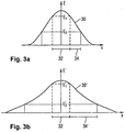
- Fig. 3 (a) shows by way of example a substantially Gaussian spatial intensity distribution 30 of a laser beam. The fluence therefore decreases from the center to the edge.
- a cutting region 32 the laser beam intensity exceeds the minimum energy E1 required to cut the paper 18.
- E2 is in Fig. 3 (a) denotes a reaction energy of the effect pigments of the marking substance, when said color change occurs beyond said.
- a marking region 34 the fluence between the reaction energy E2 required for the color change and the minimum energy E1 required for cutting is present, so that a color change of the effect pigments is induced in this region 34 but paper 18 is not cut.
- the paper 18 is therefore discolored when laser cutting by the laser beam in a zone at the edge of each hole 16 in perfect registration to the hole 16.
- the width of the colored zone at the edge corresponds to the width of the marking region 34 and depends on the intensity distribution 30 over the beam cross section, in this case the reaction energy of the effect pigments used and the material properties of the paper 18.
- the laser beam intensity is below the reaction energy of the effect pigments, so that the paper 18 is not changed in color there.
- the laser-radiation-modifiable marking substance 19 can be applied to the paper 18, for example by printing it on (cf. Fig. 3 (c) ), or can be introduced into the volume. This can already be done during papermaking by admixture of the effect pigments to the paper pulp during sheet formation or else subsequently in an immersion bath or by impregnation, for example in a size press.
- thermoreactive color pigments which change their visible color by the action of the laser radiation
- thermoreactive color pigments such as ultramarine blue
- effect pigments with different threshold energies or a combination of visually and mechanically detectable effect pigments can also be used to produce a plurality of registered edge effects.
- Non-pigmented, laser-radiation-modifiable coatings can have a very high transparency in the unlabeled state.
- a CO 2 laser at 10600 nm can be produced at high speed permanent and high-contrast markers, such as a black lettering in the coating.
- the modified edge area of the opening may optionally be even larger than the beam extent, as in FIG Fig. 3 (b) clarified.
- Fig. 3 (b) schematically shows the spatial distribution 30 'of the heat energy when cutting an opening with the laser beam of Fig. 3 (a) is produced.
- the heated area may extend beyond the jet diameter due to heat conduction.
- the paper 18 is cut in the cutting region 32, since there exceeds the laser energy E required for cutting threshold energy E1. Reacts the paper 18 or the marker 19 now at least also on the heat energy generated during cutting, then results in the for Fig. 3 (b) assumed ratios a marking region 34 ', the extent of which can easily be greater than the cross section of the laser beam. With E2 'is the necessary here Called reaction energy, beyond which the desired color change occurs,
- the marker 19 is removed or destroyed immediately adjacent to the cutting edge, and is modified only from a certain small distance from the cutting edge.
- Fig. 3 (c) shows the effect of the laser beam with the intensity distribution 30 on the paper 18.
- the paper 18 is coated with the marking substance 19.
- a laser beam 44 intersects a hole 16 having a hole diameter C, the hole being cross-sectioned as in FIG Fig. 3 (d) to see, exemplary conical runs.
- hole diameter is in Fig. 3 (d) the minimum hole diameter C is recorded, which results at the exit side of the laser beam 44 from the paper 18.
- a maximum hole diameter which is greater by a two-fold removal width B than the minimum hole diameter C.
- the sum of C and 2B results in the maximum hole diameter, which should also be denoted below by (C + 2B).
- the marker 19 is modified to provide an annular zone 20 which surrounds the hole 16 at the entrance side of the laser beam 44 and which is color coded.
- the hole 16 thus shows a colored border in plan view.
- the holes 16 in the perforated surface 14 are relatively narrow staggered according to the dot matrix R, such as Fig. 4 shows.
- the holes 16 are exemplified in the dot grid R in a hexagonal arrangement in which the hole spacing D, which denotes the distance between the centers of individual holes 16, has been chosen so that the areas of edge effect are just touching.
- the hole spacing D thus corresponds to the dimension (C + 2B) + 2A of Fig. 3 (c) , This is a marginal effect diameter E of Fig. 4
- the holes 16 are in Fig. 4 arranged exactly at this distance E.
- the arrangement of the holes in a dot matrix is optional. It is also a quasi-statistical arrangement of the holes possible, which complies with the stated area proportions of hole and surface.
- the colored impression in the incident light which arises when viewing the surface 16 by the juxtaposition of zones 20, of course, is also retained in other hole arrangements and hole spacings. From a hole spacing of the order of 2.5 times the rim diameter E, ie 2.5 times the sum of the maximum hole diameter (C + 2B) plus 2 times the zone width A, the colored impression becomes insufficient.
- a green edge effect can be generated, for example, with the aid of the marking substance Manganese Ferrite F9900 M. Its color change goes from gray to green. Of course, other color changes are conceivable, for example, from red to gray with the dye Oxide Red PR222. Both dyes are from Cathay Industries. A color change from yellow to red is with the dye iron oxide yellow FeO (OH), available for example from Lanxess, possible. A color change from turquoise to black is with the dye copper (II) oxalate, available for example from Dr. med. Paul Lohmann GmbH, possible.
- the laser beam 44 has an intensity distribution which is not constant, ie has no top hat profile. Any intensity profile in which the intensity of the laser beam 44 decreases toward the edge of the beam cross-section versus the maximum value may be used to create a zone 20, the type of intensity profile naturally being the width of the zone 20 relative to the maximum hole diameter (C + 2B) of each hole 16.
- the edge effect can also be formed along the entire hole edge, as in FIG Fig. 5 it can be seen when the marker 19 is incorporated not only on the surface, but in the volume 42 of the paper 18, as shown in FIG Fig. 5 (a) is shown, or the paper 18 is modified directly.
- an oblique hole edge 46 is generated, as it Fig. 5 (b) and (c) demonstrate.
- the energy threshold value required for the reaction of the paper 18 / marking substance 19 is thereby exceeded in an edge region 48 along the oblique hole edge 46 and the paper / marking substance is modified.
- a narrower or wider modified edge region 48 is thus produced, as is the case with the laser beam 44 Fig. 5 (b) and (c) illustrate.
- Fig. 5 (a) to (c) show only the production of a hole 16 by way of example, and also the volume provided with the marking substance 19 is only for a hole drawn. This was done for the sake of simplicity of illustration only. In fact, of course, the holes are as in Fig. 4 shown closely spaced in the surface 19 provided.
- a specific design impression can be obtained by varying the hole spacing of the perforation, for example by lateral variation of the dot matrix R or by gridless arrangement of the holes.
- the hole spacing of the perforation for example by lateral variation of the dot matrix R or by gridless arrangement of the holes.
- the color impression decreases towards the top, since in the surface 14 surface components increase that do not carry a zone 20.
- a red coloration can be achieved by laser irradiation of a coating, for example containing Polyplast PY-383 or the already mentioned iron oxide yellow.
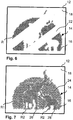
- Fig. 6 shows exemplary strip-shaped regions 22 in which the marker 19 is missing.
- Fig. 7 shows a development in which in the area 14 different motifs are represented by different patterns 24, 26 and 28, which differ in their geometry of the dot matrix.
- a pentagonal grid R1 is used for the background, a square grid R2 for the elephant and a hexagonal grid R3 for the baby elephant.
- a good recognition of the three patterns 24, 26 and 28 can also be achieved, in particular with comparatively large holes which are to be resolved with the eye, whereas no distinction appears in supervision.
- the geometry differences may also affect other parameters, as explained in the general part of the description.
- Fig. 8 shows a plan view of a further embodiment of the security feature 12. Elements which correspond to those of the previous embodiments are provided with the same reference numerals, so that their description need not be repeated.
- the security feature 12 includes edge-colored holes 16, which are arranged in a grid R. At individual positions in the grid R no hole 16, but only a colored dot 49 is formed.
- the thus formed surface of holes 16 thus has not only an outer boundary, the in Fig. 8 has the shape of an "L" but also has an inner boundary that effects encodings 50.
- the dots 49 are held in the same color as the marker 19 of the holes 16 is colored. As a result, the colored dots 49 can not be seen in plan view of the security feature 12. They appear in the same color as the rest of the area, which is colored by the colored edges of the holes 16. When viewed in transmitted light, the missing holes 16 of course fall immediately, so that the codes 50 are clearly visible.
- Fig. 9 shows a modification of the embodiment of the Fig. 8 in that a plurality of inner boundaries are present, by the security feature 12 alternates of line-lined holes 16 formed with line-shaped colored dots 49 is formed. Again, a motif is visible in plan view, for example in the form of a "P", which contains a line structure when viewed through the holes 16.
- the colored dots 49 are again colored in the color which the marker 19 has at the edges of the holes 16.
- the security element of Fig. 9 is thus made up of a plurality of surfaces, each of which is formed of line-shaped juxtaposed holes 16.
- the embodiment of the Fig. 9 thus makes a modification Fig. 8 not a surface having inner and outer boundaries, but a plurality of adjacent, here line-shaped surfaces, the optional feature being that these surfaces are arranged together with colored dots 49 in a common grid R with respect to the points and the holes ,
- Fig. 8 and 9 Due to the embodiments according to Fig. 8 and 9 for example, designs may be combined and / or hidden information, such as numbers, geometries, or specific encodings within the raster, that are visible only when viewed through the holes 16. This is possible for example by the colored dots 49 are hidden within a grid R (embodiment of the Fig. 8 ) or by the adjacent and colored holes 16 are visible only in transmitted light ( Fig. 9 ).
- the adjacent holes which are directly adjacent to one another, can also be arranged in the form of a line which, for example, represents a colored border of a motif, this border then clearly emerging when viewed through the holes 16.
- a paper 18 has been mentioned by way of example as substrate of the banknote.
- a film or the like may be used as the substrate be used, for example, in a window area of a banknote.
Landscapes
- Physics & Mathematics (AREA)
- Health & Medical Sciences (AREA)
- Electromagnetism (AREA)
- General Health & Medical Sciences (AREA)
- Toxicology (AREA)
- Engineering & Computer Science (AREA)
- Manufacturing & Machinery (AREA)
- Optics & Photonics (AREA)
- Credit Cards Or The Like (AREA)
- Laser Beam Processing (AREA)
- Thermal Transfer Or Thermal Recording In General (AREA)
Priority Applications (1)
| Application Number | Priority Date | Filing Date | Title |
|---|---|---|---|
| PL16716165T PL3291999T3 (pl) | 2015-05-04 | 2016-04-11 | Cecha bezpieczeństwa i sposób jej wytwarzania |
Applications Claiming Priority (2)
| Application Number | Priority Date | Filing Date | Title |
|---|---|---|---|
| DE102015005672.7A DE102015005672A1 (de) | 2015-05-04 | 2015-05-04 | Sicherheitsmerkmal und Verfahren zu dessen Herstellung |
| PCT/EP2016/000595 WO2016177447A1 (de) | 2015-05-04 | 2016-04-11 | Sicherheitsmerkmal und verfahren zu dessen herstellung |
Publications (2)
| Publication Number | Publication Date |
|---|---|
| EP3291999A1 EP3291999A1 (de) | 2018-03-14 |
| EP3291999B1 true EP3291999B1 (de) | 2019-04-03 |
Family
ID=55752246
Family Applications (1)
| Application Number | Title | Priority Date | Filing Date |
|---|---|---|---|
| EP16716165.2A Active EP3291999B1 (de) | 2015-05-04 | 2016-04-11 | Sicherheitsmerkmal und verfahren zu dessen herstellung |
Country Status (5)
| Country | Link |
|---|---|
| EP (1) | EP3291999B1 (pl) |
| DE (1) | DE102015005672A1 (pl) |
| ES (1) | ES2730450T3 (pl) |
| PL (1) | PL3291999T3 (pl) |
| WO (1) | WO2016177447A1 (pl) |
Families Citing this family (3)
| Publication number | Priority date | Publication date | Assignee | Title |
|---|---|---|---|---|
| DE102016014845A1 (de) | 2016-12-13 | 2018-06-14 | Giesecke+Devrient Currency Technology Gmbh | Laserschneiden und Laserverfärben von Sicherheitsdokumenten |
| GB2576573C (en) | 2018-08-24 | 2024-02-21 | Hid Cid Ltd | A security sheet and a security booklet |
| DE102024112441A1 (de) * | 2024-05-03 | 2025-11-06 | Bundesdruckerei Gmbh | Dokument mit einem Sicherheitsmerkmal |
Family Cites Families (22)
| Publication number | Priority date | Publication date | Assignee | Title |
|---|---|---|---|---|
| US842028A (en) | 1905-09-18 | 1907-01-22 | Edward F Shue | Sound-recording and reproducing mechanism. |
| US4343885A (en) | 1978-05-09 | 1982-08-10 | Dynachem Corporation | Phototropic photosensitive compositions containing fluoran colorformer |
| JPH0682188B2 (ja) | 1987-03-19 | 1994-10-19 | ザイトロニクス,インコーポレイテツド | 紫外線被曝を可視化したフィルム及び紫外線被曝量測定部材 |
| DE4334848C1 (de) | 1993-10-13 | 1995-01-05 | Kurz Leonhard Fa | Wertpapier mit Fenster |
| US8048605B2 (en) | 2001-03-16 | 2011-11-01 | Datalase Ltd | Laser-markable compositions |
| EP1657072B3 (en) | 2001-03-16 | 2016-08-31 | DataLase Ltd | Laser-imaging method |
| NL1018137C2 (nl) * | 2001-05-23 | 2002-11-26 | Nl Bank Nv | Document omvattende een authenticiteitkenmerk. |
| GB0114266D0 (en) | 2001-06-12 | 2001-08-01 | Ciba Sc Holding Ag | Laser marking method |
| US7270919B2 (en) | 2002-11-12 | 2007-09-18 | Datalase Ltd. | Use of transition metal compounds in imageable coatings |
| WO2005012442A1 (en) | 2003-07-30 | 2005-02-10 | Datalase Ltd. | Laser-arkable compositions |
| GB0400813D0 (en) | 2004-01-14 | 2004-02-18 | Sherwood Technology Ltd | Laser imaging |
| US7998900B2 (en) | 2004-11-12 | 2011-08-16 | Datalase Ltd. | Photothermal recording medium |
| GB0428299D0 (en) | 2004-12-24 | 2005-01-26 | Ciba Sc Holding Ag | Coating compositions for marking substrates |
| MY143187A (en) | 2005-03-23 | 2011-03-31 | Ciba Holding Inc | Coating compositions for marking substrates |
| GB0521513D0 (en) | 2005-10-21 | 2005-11-30 | Sherwood Technology Ltd | Laser marking on substrates |
| GB0524673D0 (en) | 2005-12-02 | 2006-01-11 | Sherwood Technology Ltd | Laser-imageable marking composition |
| RU2008135122A (ru) | 2006-01-31 | 2010-03-10 | Циба Холдинг Инк. (Ch) | Композиция покрытия для маркировки подложек |
| GB0611325D0 (en) | 2006-06-08 | 2006-07-19 | Datalase Ltd | Laser marking |
| WO2008083912A1 (en) | 2007-01-09 | 2008-07-17 | Ciba Holding Inc. | Electromagnetic radiation or thermally sensitive composition |
| DE102007036623A1 (de) | 2007-07-03 | 2009-01-08 | Giesecke & Devrient Gmbh | Sicherheitsmerkmal und Verfahren zu seiner Herstellung |
| GB0801440D0 (en) | 2008-01-25 | 2008-03-05 | Datalase Ltd | Polychromic substances and their use |
| WO2010029329A1 (en) | 2008-09-10 | 2010-03-18 | Datalase Ltd. | Energy activated compositions |
-
2015
- 2015-05-04 DE DE102015005672.7A patent/DE102015005672A1/de not_active Withdrawn
-
2016
- 2016-04-11 WO PCT/EP2016/000595 patent/WO2016177447A1/de not_active Ceased
- 2016-04-11 PL PL16716165T patent/PL3291999T3/pl unknown
- 2016-04-11 ES ES16716165T patent/ES2730450T3/es active Active
- 2016-04-11 EP EP16716165.2A patent/EP3291999B1/de active Active
Non-Patent Citations (1)
| Title |
|---|
| None * |
Also Published As
| Publication number | Publication date |
|---|---|
| ES2730450T3 (es) | 2019-11-11 |
| DE102015005672A1 (de) | 2016-11-10 |
| EP3291999A1 (de) | 2018-03-14 |
| PL3291999T3 (pl) | 2019-10-31 |
| WO2016177447A1 (de) | 2016-11-10 |
Similar Documents
| Publication | Publication Date | Title |
|---|---|---|
| EP2164707B1 (de) | Sicherheitsmerkmal und verfahren zu seiner herstellung | |
| EP2379339B1 (de) | Datenträger mit durchsichtsbereich | |
| DE3634857C2 (de) | Ausweiskarte mit visuell sichtbarem Echtheitsmerkmal und Verfahren zur Herstellung derselben | |
| EP1458577B1 (de) | Sicherheitselement und verfahren seiner herstellung | |
| EP1744899B1 (de) | Wertdokument | |
| EP0628431A1 (de) | Mehrschichtiger Aufzeichnungsträger und Verfahren zum Beschriften eines mehrschichtigen Aufzeichnungsträgers | |
| EP2580069B1 (de) | Datenträger mit merkmalsbereich und verfahren | |
| EP3823840B1 (de) | Sicherheitselement mit linsenrasterbild | |
| EP3578379B1 (de) | Sicherheitselement mit farbiger abbildung | |
| EP2941355B1 (de) | Verfahren zum herstellen eines sicherheitselements mit einer lasersensitiven aufzeichnungsschicht | |
| EP3291999B1 (de) | Sicherheitsmerkmal und verfahren zu dessen herstellung | |
| DE102008033693A1 (de) | Datenträger mit einem gedruckten magnetischen Sicherheitsmerkmal | |
| EP2678170A2 (de) | Individualisiertes durchsichtsregister | |
| EP3243669B1 (de) | Verfahren zur herstellung eines sicherheitsmerkmals | |
| DE102004027306A1 (de) | Wertdokument | |
| EP3254865B1 (de) | Merkmal und verfahren zu dessen herstellung | |
| EP1858605B1 (de) | Sichern von information | |
| EP3666542A2 (de) | Verfahren zum herstellen eines laminats und laminat sowie sicherheits- oder wertdokument mit einem innenliegenden sicherheitsmerkmal | |
| EP3254864B1 (de) | Merkmal und verfahren zu dessen herstellung | |
| EP3279004A1 (de) | Sicherheitselement, verfahren zum herstellen eines sicherheitselements sowie wertdokument mit einem solchen sicherheitselement | |
| EP3231625B1 (de) | Ein verfahren zur laserbehandlung einer beschichtung mit effektpigmenten | |
| EP3286010B1 (de) | Verfahren zum herstellen eines sicherheitselementes mit passer zwischen druckelement und wasserzeichen | |
| EP3072703A2 (de) | Verfahren zum herstellen eines fensters in einem papiersubstrat mit einem sicherheitselement |
Legal Events
| Date | Code | Title | Description |
|---|---|---|---|
| STAA | Information on the status of an ep patent application or granted ep patent |
Free format text: STATUS: THE INTERNATIONAL PUBLICATION HAS BEEN MADE |
|
| PUAI | Public reference made under article 153(3) epc to a published international application that has entered the european phase |
Free format text: ORIGINAL CODE: 0009012 |
|
| STAA | Information on the status of an ep patent application or granted ep patent |
Free format text: STATUS: REQUEST FOR EXAMINATION WAS MADE |
|
| 17P | Request for examination filed |
Effective date: 20171204 |
|
| AK | Designated contracting states |
Kind code of ref document: A1 Designated state(s): AL AT BE BG CH CY CZ DE DK EE ES FI FR GB GR HR HU IE IS IT LI LT LU LV MC MK MT NL NO PL PT RO RS SE SI SK SM TR |
|
| AX | Request for extension of the european patent |
Extension state: BA ME |
|
| DAV | Request for validation of the european patent (deleted) | ||
| DAX | Request for extension of the european patent (deleted) | ||
| GRAP | Despatch of communication of intention to grant a patent |
Free format text: ORIGINAL CODE: EPIDOSNIGR1 |
|
| STAA | Information on the status of an ep patent application or granted ep patent |
Free format text: STATUS: GRANT OF PATENT IS INTENDED |
|
| INTG | Intention to grant announced |
Effective date: 20181119 |
|
| GRAS | Grant fee paid |
Free format text: ORIGINAL CODE: EPIDOSNIGR3 |
|
| GRAA | (expected) grant |
Free format text: ORIGINAL CODE: 0009210 |
|
| STAA | Information on the status of an ep patent application or granted ep patent |
Free format text: STATUS: THE PATENT HAS BEEN GRANTED |
|
| AK | Designated contracting states |
Kind code of ref document: B1 Designated state(s): AL AT BE BG CH CY CZ DE DK EE ES FI FR GB GR HR HU IE IS IT LI LT LU LV MC MK MT NL NO PL PT RO RS SE SI SK SM TR |
|
| REG | Reference to a national code |
Ref country code: GB Ref legal event code: FG4D Free format text: NOT ENGLISH |
|
| REG | Reference to a national code |
Ref country code: CH Ref legal event code: EP Ref country code: AT Ref legal event code: REF Ref document number: 1115237 Country of ref document: AT Kind code of ref document: T Effective date: 20190415 |
|
| REG | Reference to a national code |
Ref country code: DE Ref legal event code: R096 Ref document number: 502016004009 Country of ref document: DE |
|
| REG | Reference to a national code |
Ref country code: IE Ref legal event code: FG4D Free format text: LANGUAGE OF EP DOCUMENT: GERMAN |
|
| REG | Reference to a national code |
Ref country code: NL Ref legal event code: FP |
|
| REG | Reference to a national code |
Ref country code: LT Ref legal event code: MG4D |
|
| PG25 | Lapsed in a contracting state [announced via postgrant information from national office to epo] |
Ref country code: AL Free format text: LAPSE BECAUSE OF FAILURE TO SUBMIT A TRANSLATION OF THE DESCRIPTION OR TO PAY THE FEE WITHIN THE PRESCRIBED TIME-LIMIT Effective date: 20190403 Ref country code: PT Free format text: LAPSE BECAUSE OF FAILURE TO SUBMIT A TRANSLATION OF THE DESCRIPTION OR TO PAY THE FEE WITHIN THE PRESCRIBED TIME-LIMIT Effective date: 20190803 Ref country code: SE Free format text: LAPSE BECAUSE OF FAILURE TO SUBMIT A TRANSLATION OF THE DESCRIPTION OR TO PAY THE FEE WITHIN THE PRESCRIBED TIME-LIMIT Effective date: 20190403 Ref country code: FI Free format text: LAPSE BECAUSE OF FAILURE TO SUBMIT A TRANSLATION OF THE DESCRIPTION OR TO PAY THE FEE WITHIN THE PRESCRIBED TIME-LIMIT Effective date: 20190403 Ref country code: NO Free format text: LAPSE BECAUSE OF FAILURE TO SUBMIT A TRANSLATION OF THE DESCRIPTION OR TO PAY THE FEE WITHIN THE PRESCRIBED TIME-LIMIT Effective date: 20190703 Ref country code: HR Free format text: LAPSE BECAUSE OF FAILURE TO SUBMIT A TRANSLATION OF THE DESCRIPTION OR TO PAY THE FEE WITHIN THE PRESCRIBED TIME-LIMIT Effective date: 20190403 Ref country code: LT Free format text: LAPSE BECAUSE OF FAILURE TO SUBMIT A TRANSLATION OF THE DESCRIPTION OR TO PAY THE FEE WITHIN THE PRESCRIBED TIME-LIMIT Effective date: 20190403 Ref country code: CZ Free format text: LAPSE BECAUSE OF FAILURE TO SUBMIT A TRANSLATION OF THE DESCRIPTION OR TO PAY THE FEE WITHIN THE PRESCRIBED TIME-LIMIT Effective date: 20190403 |
|
| REG | Reference to a national code |
Ref country code: DE Ref legal event code: R119 Ref document number: 502016004009 Country of ref document: DE |
|
| REG | Reference to a national code |
Ref country code: ES Ref legal event code: FG2A Ref document number: 2730450 Country of ref document: ES Kind code of ref document: T3 Effective date: 20191111 |
|
| PG25 | Lapsed in a contracting state [announced via postgrant information from national office to epo] |
Ref country code: RS Free format text: LAPSE BECAUSE OF FAILURE TO SUBMIT A TRANSLATION OF THE DESCRIPTION OR TO PAY THE FEE WITHIN THE PRESCRIBED TIME-LIMIT Effective date: 20190403 Ref country code: BG Free format text: LAPSE BECAUSE OF FAILURE TO SUBMIT A TRANSLATION OF THE DESCRIPTION OR TO PAY THE FEE WITHIN THE PRESCRIBED TIME-LIMIT Effective date: 20190703 Ref country code: GR Free format text: LAPSE BECAUSE OF FAILURE TO SUBMIT A TRANSLATION OF THE DESCRIPTION OR TO PAY THE FEE WITHIN THE PRESCRIBED TIME-LIMIT Effective date: 20190704 Ref country code: LV Free format text: LAPSE BECAUSE OF FAILURE TO SUBMIT A TRANSLATION OF THE DESCRIPTION OR TO PAY THE FEE WITHIN THE PRESCRIBED TIME-LIMIT Effective date: 20190403 |
|
| REG | Reference to a national code |
Ref country code: CH Ref legal event code: PL |
|
| REG | Reference to a national code |
Ref country code: BE Ref legal event code: MM Effective date: 20190430 |
|
| PG25 | Lapsed in a contracting state [announced via postgrant information from national office to epo] |
Ref country code: IS Free format text: LAPSE BECAUSE OF FAILURE TO SUBMIT A TRANSLATION OF THE DESCRIPTION OR TO PAY THE FEE WITHIN THE PRESCRIBED TIME-LIMIT Effective date: 20190803 Ref country code: LU Free format text: LAPSE BECAUSE OF NON-PAYMENT OF DUE FEES Effective date: 20190411 |
|
| PG25 | Lapsed in a contracting state [announced via postgrant information from national office to epo] |
Ref country code: CH Free format text: LAPSE BECAUSE OF NON-PAYMENT OF DUE FEES Effective date: 20190430 Ref country code: MC Free format text: LAPSE BECAUSE OF FAILURE TO SUBMIT A TRANSLATION OF THE DESCRIPTION OR TO PAY THE FEE WITHIN THE PRESCRIBED TIME-LIMIT Effective date: 20190403 Ref country code: EE Free format text: LAPSE BECAUSE OF FAILURE TO SUBMIT A TRANSLATION OF THE DESCRIPTION OR TO PAY THE FEE WITHIN THE PRESCRIBED TIME-LIMIT Effective date: 20190403 Ref country code: DK Free format text: LAPSE BECAUSE OF FAILURE TO SUBMIT A TRANSLATION OF THE DESCRIPTION OR TO PAY THE FEE WITHIN THE PRESCRIBED TIME-LIMIT Effective date: 20190403 Ref country code: RO Free format text: LAPSE BECAUSE OF FAILURE TO SUBMIT A TRANSLATION OF THE DESCRIPTION OR TO PAY THE FEE WITHIN THE PRESCRIBED TIME-LIMIT Effective date: 20190403 Ref country code: SK Free format text: LAPSE BECAUSE OF FAILURE TO SUBMIT A TRANSLATION OF THE DESCRIPTION OR TO PAY THE FEE WITHIN THE PRESCRIBED TIME-LIMIT Effective date: 20190403 Ref country code: LI Free format text: LAPSE BECAUSE OF NON-PAYMENT OF DUE FEES Effective date: 20190430 Ref country code: DE Free format text: LAPSE BECAUSE OF NON-PAYMENT OF DUE FEES Effective date: 20191101 |
|
| PLBE | No opposition filed within time limit |
Free format text: ORIGINAL CODE: 0009261 |
|
| STAA | Information on the status of an ep patent application or granted ep patent |
Free format text: STATUS: NO OPPOSITION FILED WITHIN TIME LIMIT |
|
| PG25 | Lapsed in a contracting state [announced via postgrant information from national office to epo] |
Ref country code: BE Free format text: LAPSE BECAUSE OF NON-PAYMENT OF DUE FEES Effective date: 20190430 Ref country code: IT Free format text: LAPSE BECAUSE OF FAILURE TO SUBMIT A TRANSLATION OF THE DESCRIPTION OR TO PAY THE FEE WITHIN THE PRESCRIBED TIME-LIMIT Effective date: 20190403 Ref country code: SM Free format text: LAPSE BECAUSE OF FAILURE TO SUBMIT A TRANSLATION OF THE DESCRIPTION OR TO PAY THE FEE WITHIN THE PRESCRIBED TIME-LIMIT Effective date: 20190403 |
|
| 26N | No opposition filed |
Effective date: 20200106 |
|
| PG25 | Lapsed in a contracting state [announced via postgrant information from national office to epo] |
Ref country code: TR Free format text: LAPSE BECAUSE OF FAILURE TO SUBMIT A TRANSLATION OF THE DESCRIPTION OR TO PAY THE FEE WITHIN THE PRESCRIBED TIME-LIMIT Effective date: 20190403 |
|
| PG25 | Lapsed in a contracting state [announced via postgrant information from national office to epo] |
Ref country code: IE Free format text: LAPSE BECAUSE OF NON-PAYMENT OF DUE FEES Effective date: 20190411 |
|
| PG25 | Lapsed in a contracting state [announced via postgrant information from national office to epo] |
Ref country code: SI Free format text: LAPSE BECAUSE OF FAILURE TO SUBMIT A TRANSLATION OF THE DESCRIPTION OR TO PAY THE FEE WITHIN THE PRESCRIBED TIME-LIMIT Effective date: 20190403 |
|
| GBPC | Gb: european patent ceased through non-payment of renewal fee |
Effective date: 20200411 |
|
| PG25 | Lapsed in a contracting state [announced via postgrant information from national office to epo] |
Ref country code: GB Free format text: LAPSE BECAUSE OF NON-PAYMENT OF DUE FEES Effective date: 20200411 |
|
| PG25 | Lapsed in a contracting state [announced via postgrant information from national office to epo] |
Ref country code: CY Free format text: LAPSE BECAUSE OF FAILURE TO SUBMIT A TRANSLATION OF THE DESCRIPTION OR TO PAY THE FEE WITHIN THE PRESCRIBED TIME-LIMIT Effective date: 20190403 |
|
| PG25 | Lapsed in a contracting state [announced via postgrant information from national office to epo] |
Ref country code: MT Free format text: LAPSE BECAUSE OF FAILURE TO SUBMIT A TRANSLATION OF THE DESCRIPTION OR TO PAY THE FEE WITHIN THE PRESCRIBED TIME-LIMIT Effective date: 20190403 Ref country code: HU Free format text: LAPSE BECAUSE OF FAILURE TO SUBMIT A TRANSLATION OF THE DESCRIPTION OR TO PAY THE FEE WITHIN THE PRESCRIBED TIME-LIMIT; INVALID AB INITIO Effective date: 20160411 |
|
| PGFP | Annual fee paid to national office [announced via postgrant information from national office to epo] |
Ref country code: FR Payment date: 20210421 Year of fee payment: 6 |
|
| REG | Reference to a national code |
Ref country code: AT Ref legal event code: MM01 Ref document number: 1115237 Country of ref document: AT Kind code of ref document: T Effective date: 20210411 |
|
| PG25 | Lapsed in a contracting state [announced via postgrant information from national office to epo] |
Ref country code: MK Free format text: LAPSE BECAUSE OF FAILURE TO SUBMIT A TRANSLATION OF THE DESCRIPTION OR TO PAY THE FEE WITHIN THE PRESCRIBED TIME-LIMIT Effective date: 20190403 |
|
| PG25 | Lapsed in a contracting state [announced via postgrant information from national office to epo] |
Ref country code: AT Free format text: LAPSE BECAUSE OF NON-PAYMENT OF DUE FEES Effective date: 20210411 |
|
| PG25 | Lapsed in a contracting state [announced via postgrant information from national office to epo] |
Ref country code: FR Free format text: LAPSE BECAUSE OF NON-PAYMENT OF DUE FEES Effective date: 20220430 |
|
| P01 | Opt-out of the competence of the unified patent court (upc) registered |
Effective date: 20230520 |
|
| PGFP | Annual fee paid to national office [announced via postgrant information from national office to epo] |
Ref country code: ES Payment date: 20230517 Year of fee payment: 8 |
|
| PGFP | Annual fee paid to national office [announced via postgrant information from national office to epo] |
Ref country code: PL Payment date: 20250328 Year of fee payment: 10 |
|
| PGFP | Annual fee paid to national office [announced via postgrant information from national office to epo] |
Ref country code: NL Payment date: 20250422 Year of fee payment: 10 |
|
| REG | Reference to a national code |
Ref country code: ES Ref legal event code: FD2A Effective date: 20250529 |
|
| PG25 | Lapsed in a contracting state [announced via postgrant information from national office to epo] |
Ref country code: ES Free format text: LAPSE BECAUSE OF NON-PAYMENT OF DUE FEES Effective date: 20240412 |