EP3292071B1 - Procédé et dispositif de surveillance d'appui pour chariot comportant un moyen de stabilisateur - Google Patents
Procédé et dispositif de surveillance d'appui pour chariot comportant un moyen de stabilisateur Download PDFInfo
- Publication number
- EP3292071B1 EP3292071B1 EP16726132.0A EP16726132A EP3292071B1 EP 3292071 B1 EP3292071 B1 EP 3292071B1 EP 16726132 A EP16726132 A EP 16726132A EP 3292071 B1 EP3292071 B1 EP 3292071B1
- Authority
- EP
- European Patent Office
- Prior art keywords
- trolley
- monitoring
- support
- elevation
- calculation
- Prior art date
- Legal status (The legal status is an assumption and is not a legal conclusion. Google has not performed a legal analysis and makes no representation as to the accuracy of the status listed.)
- Active
Links
Images

Classifications
-
- B—PERFORMING OPERATIONS; TRANSPORTING
- B66—HOISTING; LIFTING; HAULING
- B66F—HOISTING, LIFTING, HAULING OR PUSHING, NOT OTHERWISE PROVIDED FOR, e.g. DEVICES WHICH APPLY A LIFTING OR PUSHING FORCE DIRECTLY TO THE SURFACE OF A LOAD
- B66F9/00—Devices for lifting or lowering bulky or heavy goods for loading or unloading purposes
- B66F9/06—Devices for lifting or lowering bulky or heavy goods for loading or unloading purposes movable, with their loads, on wheels or the like, e.g. fork-lift trucks
- B66F9/075—Constructional features or details
- B66F9/07559—Stabilizing means
-
- B—PERFORMING OPERATIONS; TRANSPORTING
- B66—HOISTING; LIFTING; HAULING
- B66C—CRANES; LOAD-ENGAGING ELEMENTS OR DEVICES FOR CRANES, CAPSTANS, WINCHES, OR TACKLES
- B66C23/00—Cranes comprising essentially a beam, boom, or triangular structure acting as a cantilever and mounted for translatory of swinging movements in vertical or horizontal planes or a combination of such movements, e.g. jib-cranes, derricks, tower cranes
- B66C23/62—Constructional features or details
- B66C23/72—Counterweights or supports for balancing lifting couples
- B66C23/78—Supports, e.g. outriggers, for mobile cranes
- B66C23/80—Supports, e.g. outriggers, for mobile cranes hydraulically actuated
-
- E—FIXED CONSTRUCTIONS
- E02—HYDRAULIC ENGINEERING; FOUNDATIONS; SOIL SHIFTING
- E02F—DREDGING; SOIL-SHIFTING
- E02F9/00—Component parts of dredgers or soil-shifting machines, not restricted to one of the kinds covered by groups E02F3/00 - E02F7/00
- E02F9/08—Superstructures; Supports for superstructures
- E02F9/085—Ground-engaging fitting for supporting the machines while working, e.g. outriggers, legs
-
- E—FIXED CONSTRUCTIONS
- E02—HYDRAULIC ENGINEERING; FOUNDATIONS; SOIL SHIFTING
- E02F—DREDGING; SOIL-SHIFTING
- E02F9/00—Component parts of dredgers or soil-shifting machines, not restricted to one of the kinds covered by groups E02F3/00 - E02F7/00
- E02F9/26—Indicating devices
- E02F9/264—Sensors and their calibration for indicating the position of the work tool
Definitions
- the invention relates to a carriage support monitoring method comprising a stabilizer means.
- the invention also relates to a trolley support monitoring device comprising a stabilizer means.
- a first object of the invention is to provide a new support monitoring method for reacting against a loss of stability due to soil compaction or excessive sinking.
- a second object of the invention is to provide a new support monitoring device for reacting against a loss of stability and taking into account the instantaneous static state of the carriage.
- the object of the invention is a stabilizer means carriage, characterized in that said carriage is equipped with a device as described above, and in that said carriage comprises means for controlling means for descent of the means. stabilizer, said control means and the calculation and comparison means are configured for the implementation of a method as described above.
- Said control means and the calculation and comparison means may be implemented using computer and / or electronic components.
- the functions operated by said means can be performed by sets of computer instructions implemented in a processor or be performed by dedicated electronic components or components of the FPGA or ASIC type. It is also possible to combine computer parts and electronic parts.
- a stabilizer means carriage of known type comprises a self-propelled chassis comprising a non-oscillating front axle and a rear axle oscillating, a fixed section of telescopic arm, a sliding section of telescopic arm and an accessory integral with the sliding section of telescopic arm capable of carrying a load.
- the rear axle of the chassis oscillates around an axis.
- the front deck of the chassis carries at least one stabilizer means.
- the self-propelled chassis assembly carrying all its equipment and including its front and rear decks has a center of gravity located at a given distance according to an angle of inclination with respect to the horizontal plane passing through the axis of the articulation pivot of the arm telescopic on the chassis.
- the invention particularly aims to actively improve the stability of the carriage by applying a reactive action between the frame and the stabilizer means through the actuation of a double-acting cylinder of the stabilizer means.
- the invention thus makes it possible to remedy the disadvantages of a ground defect interacting with the stabilizer means of an off-road truck, which risks ending up in unstable support and overturning.
- a stabilizer means carriage according to the invention comprises a self-propelled chassis 1 comprising a non-oscillating front axle 2 and an oscillating rear axle 3.
- the rear axle of the chassis oscillates around a central axis.
- the front bridge 2 of the chassis carries at least one means 4 of stabilizer.
- the operator When the industrial truck is stationary in a horizontal position, the operator gives a descent instruction of the stabilizer means 4. As the carriage is stationary in a horizontal position, the operator can indeed actuate the stabilizer means 4 to lower its support pad 4a in contact with the ground, as shown in FIG. figure 1 .
- the predicted elevation is calculated as a function of the difference between the travel of the support pad 4a to touch the ground and the complete travel of the support pad 4a.
- the carriage comprises means for detecting the ground contact of the support pad 4a, for example by means of an overpressure detection inside a jack of the stabilizer means or using a dedicated sensor.
- the stabilizer means carriage comprising a self-propelled chassis 1 with a non-oscillating front axle 2 carrying at least one stabilizer means 4 is stationary in a horizontal position.
- the operator actuates the stabilizer means 4 to support his support pad 4a on the ground, as shown in FIG. figure 2 .
- An initial calculation of the predicted elevation H is then carried out from the theoretical parameters of the industrial truck, using the initial position reference of the stabilizer means 4 with its contact pad 4a in contact with the ground and using the stroke C output of the rod 4b of the stabilizer means 4.
- the predicted initial H-elevation calculation may optionally utilize the soil compressibility characteristics as they are known.
- the stabilizer means carriage comprising a self-propelled chassis 1 with a non-oscillating front axle 2 carrying at least one stabilizer means 4 is stationary in the raised position at the front.
- the cart computer connected to various sensors or equivalent means performs an initial calculation of actual elevation E from the parameters measured by the sensors or equivalent means of the industrial truck, using the initial reference position of the stabilizer means 4 with its support pad 4a in contact with the ground and in particular using the measured inclination of the carriage.
- the carriage is provided with sensors for measuring one or a combination of all or part of said parameters listed above.
- the initial calculation of actual elevation E can possibly use the characteristics of compressibility of the soil when they are known: the figure 3 corresponds to the case of a non-deformable soil, for example rocky.
- the actual elevation E of the figure 3 is substantially equal to the predicted elevation H of the figure 2 .
- the lifting of the truck can be continued safely and stably.
- the stabilizer means carriage comprising a self-propelled chassis 1 with a non-oscillating front axle 2 carrying at least one stabilizer means 4 is stationary in the raised position at the front.
- the cart computer connected to various sensors or equivalent means performs an initial calculation of actual elevation E from the parameters measured by the sensors or equivalent means of the industrial truck, using the initial reference of the stabilizer means 4 position with its pad 4a in contact with the ground and in particular using the measured inclination of the carriage.
- the initial calculation of actual elevation E can possibly use the characteristics of compressibility of the soil when they are known: the figure 4 corresponds to the case of a deformable soil.
- the actual elevation E of the figure 4 is substantially less than the predicted elevation H of the figure 2 .
- the invention thus makes it possible to remedy the disadvantages of a ground defect interacting with the stabilizer means of an off-road truck, which risks ending up in unstable support and overturning.
- the method according to the invention starts at a step 100, in which the industrial truck is stationary and in which the operator gives a descent instruction of the stabilizer means.
- step 101 of descent of the stabilizer means The process continues at step 101 of descent of the stabilizer means.
- step 102 a test is performed to see if the industrial truck is stationary and if the descent of the stabilizer means is effective to come into contact with the ground.
- step 102 If the test of step 102 concludes that the industrial truck is not stationary or that the descent of the stabilizer means is not sufficient to come into contact with the ground, the method loops to step 100 to possibly receive a new descent instruction of the stabilizer means.
- step 102 If the test of step 102 concludes that the industrial truck is stationary and that the descent of the stabilizer means is sufficient to arrive at the ground contact, the method continues in step 103 in which an initial calculation of predicted elevation is made from the theoretical parameters of the industrial truck, then to a step 104 in which an initial calculation of actual elevation is made to from the parameters measured by the sensors of the truck.
- An additional descent of the stabilizer means is carried out at step 105 to put the industrial truck on the stabilizer means.
- step 106 in which an update of the predicted elevation initial calculation is performed from the theoretical parameters of the industrial truck, then to a step 107 in which an update of the actual initial elevation calculation is performed to from the parameters measured by the sensors of the truck.
- step 108 a test is performed to compare the predicted elevation calculation and the actual elevation calculation and to verify their consistency.
- said calculations are coherent when the difference in absolute value between the predicted elevation calculation and the actual elevation calculation is less than 10% of the actual elevation calculation.
- the coherence calculation is weighted as a function of the accuracy of the measured and / or theoretical parameter sensors and / or as a function of terrain characteristics defined for example by the operator.
- step 108 If the test of step 108 concludes that the predicted elevation calculation and the actual elevation calculation are consistent, the method continues to step 109 of deactivating alert, then to step 111 to possibly receive a new descent instruction of the stabilizer means.
- step 108 If the test of step 108 concludes that the predicted elevation and actual elevation calculations are not consistent, the method continues at step 110 of alert activation and then at step 111 to receive possibly a new descent instruction of the stabilizer means.
- step 111 If the operator has given a descent instruction of the stabilizer means in step 111, the method will loop at step 105 of additional descent of the stabilizer means.
- step 111 If the operator has not given any instructions for descent of the stabilizer means in step 111, the process proceeds to step 112 of stabilizing completion on support of the stabilizer means.
- step 113 of start of bearer monitoring to subdivide into a motion monitor branch having steps 114 to 119 and a break monitor branch having steps 120 to 122.
- step 114 in which an initial calculation of predicted elevation is made from the theoretical parameters of the industrial truck, then to a step 115 in which an initial calculation of actual elevation is made from the measured parameters. by the sensors of the truck.
- step 116 an update of the initial calculation of actual elevation is performed from the parameters measured by the sensors of the industrial truck.
- step 117 a test is performed to compare predicted elevation and actual elevation calculations and to verify their consistency.
- step 117 If the test in step 117 concludes that the predicted elevation and actual elevation calculations are consistent, the process proceeds to step 118 of updating the actual elevation calculation.
- step 117 If the test in step 117 concludes that the predicted elevation and actual elevation calculations are not consistent, the method continues at step 119 of alert activation revealing abnormal displacements and indicating a risk of failure. 'instability.
- step 120 a soil monitoring is performed from the parameters measured by the sensors of the industrial truck, to detect a bearing break.
- step 121 a test is performed to detect an unwanted abrupt descent of the stabilizer means.
- step 121 If the test in step 121 concludes that there is no unwanted abrupt descent of the stabilizer means, the method loops at step 120 of soil monitoring performed from the parameters measured by the sensors of the industrial truck, to detect a support break.
- step 121 If the test in step 121 concludes an undesirable abrupt descent of the stabilizer means, the method continues at step 122 of alert activation revealing abnormal sudden shocks or movements and indicating a risk of instability.
- step 111 If the operator has not given any instructions for descent of the stabilizer means in step 111, the process proceeds to step 112 of stabilizing completion on support of the stabilizer means.
- it is intended to detect a possible decrease in the measured elevation value, which makes it possible to detect a stabilization problem, for example a depression of the stabilizer means, so that the operator can be alerted on a destabilization and may decide to move the cart to another location.
- a stabilization problem for example a depression of the stabilizer means
Landscapes
- Engineering & Computer Science (AREA)
- Structural Engineering (AREA)
- Civil Engineering (AREA)
- Mechanical Engineering (AREA)
- Mining & Mineral Resources (AREA)
- General Engineering & Computer Science (AREA)
- Transportation (AREA)
- Life Sciences & Earth Sciences (AREA)
- Geology (AREA)
- Vehicle Body Suspensions (AREA)
Description
- L'invention est relative à un procédé de surveillance d'appui pour chariot comportant un moyen de stabilisateur.
- L'invention est également relative à un dispositif de surveillance d'appui pour chariot comportant un moyen de stabilisateur.
- On connait de l'état de la technique et plus particulièrement du document
US2003/168421 A1 un véhicule à bras télescopique qui comprend un moyen de stabilisateur. - Un premier but de l'invention est de fournir un nouveau procédé de surveillance d'appui permettant de réagir contre une perte de stabilité due à un tassement du sol ou un enfoncement trop important.
- Un deuxième but de l'invention est de fournir un nouveau dispositif de surveillance d'appui permettant de réagir contre une perte de stabilité et tenant compte de l'état statique instantané du chariot.
- L'invention a pour objet un procédé de surveillance d'appui pour chariot comportant un moyen de stabilisateur, ledit procédé comportant des étapes :
- de descente du moyen de stabilisateur de manière à élever au moins une partie du chariot, telles que les roues avant du chariot, par rapport à un niveau de référence donné, tel que le niveau du sol ;
- de calcul d'élévation prédite de ladite au moins une partie du chariot par rapport audit niveau de référence donné ;
- de calcul d'élévation réelle de ladite au moins une partie du chariot par rapport audit niveau de référence donné effectué, le calcul étant effectué à partir de paramètres mesurés par des capteurs du chariot de manutention, et
- de comparaison du calcul d'élévation prédite et du calcul d'élévation réelle pour vérifier leur cohérence.
- L'invention a également pour objet un dispositif de surveillance d'appui pour chariot comportant un moyen de stabilisateur, comportant :
- des moyens de descente du moyen de stabilisateur permettant d'élever au moins une partie du chariot par rapport audit niveau de référence donné ;
- des moyens de calcul d'élévation prédite de ladite au moins une partie du chariot par rapport audit niveau de référence donné ;
- des moyens de calcul d'élévation réelle de ladite au moins une partie du chariot par rapport audit niveau de référence donné, à partir de paramètres mesurés par des capteurs du chariot de manutention, et
- des moyens de comparaison du calcul d'élévation prédite et du calcul d'élévation réelle pour vérifier leur cohérence.
- L'invention a enfin pour objet un chariot à moyen de stabilisateur caractérisé en ce que ledit chariot est équipé d'un dispositif tel que décrit ci-dessus, et en ce que, ledit chariot comprenant des moyens de commande des moyens de descente du moyen de stabilisateur, lesdits moyens de commande et les moyens de calcul et de comparaison sont configurés pour la mise en oeuvre d'un procédé tel que décrit ci-dessus.
- Lesdits moyens de commande et les moyens de calcul et de comparaison peuvent être réalisés à l'aide de composants informatiques et/ou électroniques. Ainsi, les fonctions opérées par lesdits moyens peuvent être réalisées par des jeux d'instructions informatiques implémentées dans un processeur ou être réalisées par des composants électroniques dédiés ou des composants de type FPGA ou ASIC. Il est aussi possible de combiner des parties informatiques et des parties électroniques.
- L'invention sera mieux comprise, grâce à la description qui va suivre donnée à titre d'exemple non limitatif en référence aux dessins annexés dans lesquels :
- La
figure 1 représente schématiquement, une vue latérale d'un chariot à moyen de stabilisateur selon l'invention. - La
figure 2 représente schématiquement, une vue latérale d'un chariot à moyen de stabilisateur selon l'invention. - La
figure 3 représente schématiquement, une vue latérale d'un chariot à moyen de stabilisateur selon l'invention. - La
figure 4 représente schématiquement, une vue latérale d'un chariot à moyen de stabilisateur selon l'invention. - La
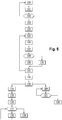
figure 5 représente schématiquement, un organigramme de fonctionnement d'un procédé de surveillance d'appui pour chariot selon l'invention. - Une référence dans toute la description à « un mode de réalisation » signifie qu'une fonctionnalité, une structure, ou une caractéristique particulière décrite en relation avec un mode de réalisation est incluse dans au moins un mode de réalisation de la présente invention. Ainsi, l'apparition de l'expression « dans un mode de réalisation » à divers emplacements dans toute la spécification ne fait pas nécessairement référence au même mode de réalisation. En outre, les fonctionnalités, les structures, ou les caractéristiques particulières peuvent être combinées de n'importe quelle manière appropriée dans un ou plusieurs modes de réalisation.
- En référence aux
figures 1 à 5 , les éléments identiques ou fonctionnellement équivalents sont repérés par des chiffres de référence identiques. - Un chariot à moyen de stabilisateur de type connu comporte un châssis automoteur comportant un pont avant non oscillant et un pont arrière oscillant, une section fixe de bras télescopique, une section coulissante de bras télescopique et un accessoire solidaire de la section coulissante de bras télescopique apte à porter une charge. Le pont arrière du châssis oscille autour d'un axe. Le pont avant du châssis porte au moins un moyen de stabilisateur.
- L'ensemble de châssis automoteur portant tous ses équipements et incluant ses ponts avant et arrière possède un centre de gravité situé à une distance donnée selon un angle d'inclinaison par rapport au plan horizontal passant par l'axe du pivot d'articulation du bras télescopique sur le châssis.
- Des moyens ou capteurs de type connu en soi sont avantageusement prévus pour déterminer continûment les paramètres suivants :
- distance et angle d'inclinaison sur l'horizontale du centre de gravité de la section fixe de bras télescopique ;
- distance et angle d'inclinaison sur l'horizontale du centre de gravité de la section coulissante de bras télescopique ;
- distance et angle d'inclinaison sur l'horizontale du centre de gravité du chargement incluant l'accessoire du bras télescopique.
- A partir des valeurs ou paramètres précités continûment mesurés, on calcule continûment une indication de la position instantanée du centre de gravité du chariot à bras télescopique. D'autres moyens de type connu sont avantageusement prévus pour déterminer continûment les paramètres suivants :
- les angles d'inclinaison du châssis par rapport à l'horizontale ;
- le rayon de braquage du chariot à bras télescopique ;
- la vitesse d'avancement du chariot à bras télescopique.
- L'invention a notamment pour objectif d'améliorer activement la stabilité du chariot en appliquant une action réactive entre le châssis et le moyen de stabilisateur grâce à l'actionnement d'un vérin à double effet du moyen de stabilisateur.
- L'invention permet ainsi de remédier aux inconvénients d'un défaut du sol en interaction avec le moyen de stabilisateur d'un chariot tout terrain, lequel risque de se retrouver en appui instable et de se renverser.
- Sur la
figure 1 , un chariot à moyen de stabilisateur selon l'invention comporte un châssis 1 automoteur comportant un pont avant 2 non oscillant et un pont arrière 3 oscillant. - Le pont arrière du châssis oscille autour d'un axe central.
- Le pont avant 2 du châssis porte au moins un moyen 4 de stabilisateur.
- Lorsque le chariot de manutention est immobile en position horizontale, l'opérateur donne une instruction de descente du moyen 4 de stabilisateur. Comme le chariot est immobile en position horizontale, l'opérateur peut en effet actionner le moyen 4 de stabilisateur pour abaisser son patin 4a d'appui au contact du sol, comme représenté à la
figure 1 . - Lorsque le chariot de manutention reste immobile et si la descente du moyen de stabilisateur ne suffit pas à arriver au contact du sol, l'opérateur donne une nouvelle instruction de descente du moyen 4 de stabilisateur.
- Cette position représentée à la
figure 1 du moyen 4 de stabilisateur avec son patin 4a d'appui au contact du sol est utilisée comme référence initiale de position. - Un calcul initial d'élévation prédite est effectué ensuite à partir des paramètres théoriques du chariot de manutention et en utilisant la référence initiale de position du moyen 4 de stabilisateur avec son patin 4a d'appui au contact du sol. Lesdits paramètres théoriques peuvent comprendre l'un ou une combinaison de tout ou partie des paramètres suivants :
- la course du patin 4a d'appui du moyen stabilisateur pour toucher le sol ; et/ou
- la course complète (ou maximale) du patin 4a d'appui du moyen stabilisateur ;
- Avantageusement, l'élévation prédite est calculée en fonction de la différence entre la course du patin 4a d'appui pour toucher le sol et la course complète du patin 4a d'appui.
- A cet effet, on peut prévoir que le chariot comprend des moyens de détection du contact au sol du patin 4a d'appui, par exemple par l'intermédiaire d'une détection de surpression à l'intérieur d'un vérin du moyen de stabilisateur ou à l'aide d'un capteur dédié.
- On peut prévoir de calculer le ou lesdits paramètres prédits sur la partie gauche et/ou droite du chariot afin de détecter une perte de stabilité latérale du chariot.
- Sur la
figure 2 , le chariot à moyen de stabilisateur selon l'invention comportant un châssis 1 automoteur avec un pont avant 2 non oscillant portant au moins un moyen 4 de stabilisateur est immobile en position horizontale. - Comme le chariot est immobile en position horizontale, l'opérateur donne une nouvelle instruction de descente du moyen 4 de stabilisateur.
- L'opérateur actionne le moyen 4 de stabilisateur pour appuyer son patin 4a d'appui sur le sol, comme représenté à la
figure 2 . - Lorsque le chariot de manutention reste immobile et si la descente du moyen de stabilisateur ne suffit pas à soulever le pont avant 2 au-dessus du sol, l'opérateur donne une nouvelle instruction de descente du moyen 4 de stabilisateur.
- Cette position représentée à la
figure 2 du moyen 4 de stabilisateur avec son patin 4a d'appui est obtenue par sortie de la tige 4b du moyen 4 de stabilisateur selon une course C. - Un calcul initial d'élévation H prédite est effectué ensuite à partir des paramètres théoriques du chariot de manutention, en utilisant la référence initiale de position du moyen 4 de stabilisateur avec son patin 4a d'appui au contact du sol et en utilisant la course C de sortie de la tige 4b du moyen 4 de stabilisateur.
- Le calcul initial d'élévation H prédite peut éventuellement utiliser les caractéristiques de compressibilité du sol lorsqu'elles sont connues.
- Sur la
figure 3 , le chariot à moyen de stabilisateur selon l'invention comportant un châssis 1 automoteur avec un pont avant 2 non oscillant portant au moins un moyen 4 de stabilisateur est immobile en position soulevée à l'avant. - Pendant que le chariot est immobile en position soulevée à l'avant, le calculateur du chariot relié à divers capteurs ou moyens équivalents effectue un calcul initial d'élévation E réelle à partir des paramètres mesurés par les capteurs ou moyens équivalents du chariot de manutention, en utilisant la référence initiale de position du moyen 4 de stabilisateur avec son patin 4a d'appui au contact du sol et en utilisant notamment l'inclinaison mesurée du chariot.
- Lesdits paramètres mesurés peuvent comprendre l'un ou une combinaison de tout ou partie des paramètres suivants :
- inclinaison du châssis du chariot autour d'un axe parallèle à l'axe des roues avant ou arrière ;
- coordonnées, par exemple issue d'un système GPS, d'une partie du chariot, telle que la partie avant, en particulier l'une des ou les roues avant du chariot, ou encore la cabine.
- Le chariot est muni de capteurs permettant de mesurer l'un ou une combinaison de tout ou partie desdits paramètres listés ci-dessus.
- On peut prévoir de mesurer le ou lesdits paramètres mesurés sur la partie gauche et/ou droite du chariot afin de détecter une perte de stabilité latérale du chariot.
- Le calcul initial d'élévation réelle E peut éventuellement utiliser les caractéristiques de compressibilité du sol lorsqu'elles sont connues : la
figure 3 correspond ainsi au cas d'un sol non déformable, par exemple rocailleux. - Dans le cas d'un sol non déformable, par exemple rocailleux, l'élévation réelle E de la
figure 3 est sensiblement égale à l'élévation prédite H de lafigure 2 . - Dans le cas d'un sol non déformable, le soulèvement du chariot peut ainsi être poursuivi en sécurité et de manière stable.
- Sur la
figure 4 , le chariot à moyen de stabilisateur selon l'invention comportant un châssis 1 automoteur avec un pont avant 2 non oscillant portant au moins un moyen 4 de stabilisateur est immobile en position soulevée à l'avant. - Pendant que le chariot est immobile en position soulevée à l'avant, le calculateur du chariot relié à divers capteurs ou moyens équivalents effectue un calcul initial d'élévation E réelle à partir des paramètres mesurés par les capteurs ou moyens équivalents du chariot de manutention, en utilisant la référence initiale de position du moyen 4 de stabilisateur avec son patin 4a d'appui au contact du sol et en utilisant notamment l'inclinaison mesurée du chariot.
- Le calcul initial d'élévation réelle E peut éventuellement utiliser les caractéristiques de compressibilité du sol lorsqu'elles sont connues : la
figure 4 correspond ainsi au cas d'un sol déformable. - Dans le cas d'un sol déformable, l'élévation réelle E de la
figure 4 est sensiblement inférieure à l'élévation prédite H de lafigure 2 . - Dans le cas d'un sol déformable, le soulèvement du chariot peut être poursuivi en sécurité uniquement en cas de déformation modérée et de tassement modéré du sol.
- L'invention permet ainsi de remédier aux inconvénients d'un défaut du sol en interaction avec le moyen de stabilisateur d'un chariot tout terrain, lequel risque de se retrouver en appui instable et de se renverser.
- Sur la
figure 5 , un procédé selon l'invention de surveillance d'appui pour chariot comportant un moyen de stabilisateur comporte des étapes 100 à 112 de stabilisation et des étapes 113 à 122 de surveillance d'appui du chariot de manutention. - Le procédé selon l'invention débute à une étape 100, dans laquelle le chariot de manutention est immobile et dans laquelle l'opérateur donne une instruction de descente du moyen de stabilisateur.
- Le procédé continue à l'étape 101 de descente du moyen de stabilisateur.
- À l'étape 102, un test est effectué pour voir si le chariot de manutention est immobile et si la descente du moyen de stabilisateur est effective pour arriver au contact du sol.
- Si le test de l'étape 102 conclut au fait que le chariot de manutention n'est pas immobile ou si la descente du moyen de stabilisateur ne suffit pas à arriver au contact du sol, le procédé boucle à l'étape 100 pour recevoir éventuellement une nouvelle instruction de descente du moyen de stabilisateur.
- Si le test de l'étape 102 conclut au fait que le chariot de manutention est immobile et si la descente du moyen de stabilisateur suffit à arriver au contact du sol, le procédé continue à l'étape 103 dans laquelle un calcul initial d'élévation prédite est effectué à partir des paramètres théoriques du chariot de manutention, puis à une étape 104 dans laquelle un calcul initial d'élévation réelle est effectué à partir des paramètres mesurés par les capteurs du chariot de manutention.
- Une descente additionnelle du moyen de stabilisateur est effectuée à l'étape 105 pour mettre le chariot de manutention en appui sur le moyen de stabilisateur.
- Le procédé continue à l'étape 106 dans laquelle une actualisation du calcul initial d'élévation prédite est effectuée à partir des paramètres théoriques du chariot de manutention, puis à une étape 107 dans laquelle une actualisation du calcul initial d'élévation réelle est effectuée à partir des paramètres mesurés par les capteurs du chariot de manutention.
- À l'étape 108, un test est effectué pour comparer le calcul d'élévation prédite et le calcul d'élévation réelle et pour vérifier leur cohérence.
- A titre d'exemple, on peut considérer que lesdits calculs sont cohérents lorsque la différence en valeur absolue entre le calcul d'élévation prédite et le calcul d'élévation réel est inférieure à 10 % du calcul d'élévation réel.
- Avantageusement, le calcul de cohérence est pondéré en fonction de la précision des capteurs de paramètres mesurés et/ou théoriques et/ou en fonction de caractéristiques du terrain définies par exemple par l'opérateur.
- Si le test de l'étape 108 conclut à la cohérence du calcul d'élévation prédite et du calcul d'élévation réelle, le procédé continue à l'étape 109 de désactivation d'alerte, puis à l'étape 111 pour recevoir éventuellement une nouvelle instruction de descente du moyen de stabilisateur.
- Si le test de l'étape 108 conclut à l'absence de cohérence des calculs d'élévation prédite et d'élévation réelle, le procédé continue à l'étape 110 d'activation d'alerte, puis à l'étape 111 pour recevoir éventuellement une nouvelle instruction de descente du moyen de stabilisateur.
- Si l'opérateur a donné une instruction de descente du moyen de stabilisateur à l'étape 111, le procédé boucle à l'étape 105 de descente additionnelle du moyen de stabilisateur.
- Si l'opérateur n'a donné aucune instruction de descente du moyen de stabilisateur à l'étape 111, le procédé continue à l'étape 112 de fin de stabilisation sur appui du moyen de stabilisateur.
- Le procédé continue ensuite à l'étape 113 de début de surveillance d'appui pour se subdiviser en une branche de surveillance de déplacements comportant des étapes 114 à 119 et une branche de surveillance de ruptures comportant des étapes 120 à 122.
- Le procédé continue à l'étape 114 dans laquelle un calcul initial d'élévation prédite est effectué à partir des paramètres théoriques du chariot de manutention, puis à une étape 115 dans laquelle un calcul initial d'élévation réelle est effectué à partir des paramètres mesurés par les capteurs du chariot de manutention.
- Le procédé continue à l'étape 116 dans laquelle une actualisation du calcul initial d'élévation réelle est effectuée à partir des paramètres mesurés par les capteurs du chariot de manutention.
- À l'étape 117, un test est effectué pour comparer les calculs d'élévation prédite et d'élévation réelle et pour vérifier leur cohérence.
- Si le test de l'étape 117 conclut à la cohérence des calculs d'élévation prédite et d'élévation réelle, le procédé continue à l'étape 118 de mise à jour du calcul d'élévation réelle.
- Si le test de l'étape 117 conclut à l'absence de cohérence des calculs d'élévation prédite et d'élévation réelle, le procédé continue à l'étape 119 d'activation d'alerte révélant des déplacements anormaux et indiquant un risque d'instabilité.
- Le procédé continue à l'étape 120 dans laquelle une surveillance du sol est effectuée à partir des paramètres mesurés par les capteurs du chariot de manutention, pour détecter une rupture d'appui.
- À l'étape 121, un test est effectué pour détecter une descente brusque indésirable du moyen de stabilisateur.
- Si le test de l'étape 121 conclut à l'absence de descente brusque indésirable du moyen de stabilisateur, le procédé boucle à l'étape 120 de surveillance du sol effectuée à partir des paramètres mesurés par les capteurs du chariot de manutention, pour détecter une rupture d'appui.
- Si le test de l'étape 121 conclut à une descente brusque indésirable du moyen de stabilisateur, le procédé continue à l'étape 122 d'activation d'alerte révélant des chocs ou mouvements brusques anormaux et indiquant un risque d'instabilité.
- L'opérateur percevant une alerte intervient pour agir sur le moyen de stabilisateur afin de placer le chariot de manutention en situation stable.
- Si l'opérateur n'a donné aucune instruction de descente du moyen de stabilisateur à l'étape 111, le procédé continue à l'étape 112 de fin de stabilisation sur appui du moyen de stabilisateur.
- Selon un mode de réalisation, il est prévu de détecter une éventuelle diminution de la valeur d'élévation mesurée, ce qui permet de détecter un problème de stabilisation, par exemple un enfoncement du moyen de stabilisateur, de sorte que l'opérateur peut être alerté sur une déstabilisation et peut décider de déplacer le chariot à un autre endroit.
- On peut prévoir aussi de calculer la vitesse de diminution de la valeur d'élévation mesurée pour détecter la cinétique d'enfoncement et ainsi bénéficier d'une information supplémentaire à prendre compte pour alerter l'opérateur.
- On peut prévoir de calculer les élévations prédites et mesurées, distinctement à droite et et à gauche du chariot, ce qui permet de détecter des enfoncements locaux et un risque de basculement.
- L'invention n'est pas limitée aux modes de réalisation illustrés dans les dessins. En conséquence, il doit être entendu que, lorsque les caractéristiques mentionnées dans les revendications annexées sont suivies par des signes de référence, ces signes sont inclus uniquement dans le but d'améliorer l'intelligibilité des revendications et ne sont nullement limitatifs de la portée des revendications.
- De plus, le terme « comprenant » n'exclut pas d'autres éléments ou étapes. En outre, des caractéristiques ou étapes qui ont été décrites en référence à l'un des modes de réalisation exposés ci-dessus peuvent également être utilisées en combinaison avec d'autres caractéristiques ou étapes d'autres modes de réalisation exposés ci-dessus.
Claims (10)
- Procédé de surveillance d'appui pour chariot comportant un moyen de stabilisateur , caractérisé en ce que ledit procédé comporte des étapes :- de descente du moyen de stabilisateur de manière à élever au moins une partie du chariot, telles que les roues avant du chariot, par rapport à un niveau de référence donné, tel que le niveau du sol ;- de calcul (103) d'élévation prédite de ladite au moins une partie du chariot par rapport audit niveau de référence donné ;- de calcul (104) d'élévation réelle de ladite au moins une partie du chariot par rapport audit niveau de référence donné, le calcul étant effectué à partir de paramètres mesurés par des capteurs du chariot de manutention, et- de comparaison (108) du calcul d'élévation prédite et du calcul d'élévation réelle pour vérifier leur cohérence.
- Procédé selon la revendication 1, comportant une étape (113) de début de surveillance d'appui.
- Procédé selon la revendication 2, dans lequel l'étape (113) de début de surveillance d'appui est suivie par des étapes (114 - 119) de surveillance de déplacements.
- Procédé selon la revendication 2 ou la revendication 3, dans lequel l'étape (113) de début de surveillance d'appui est suivie par des étapes (120 - 122) de surveillance de ruptures d'appui.
- Procédé selon la revendication 1, dans lequel une étape (106) d'actualisation du calcul d'élévation prédite est effectuée à partir des paramètres théoriques du chariot de manutention, et dans lequel une étape (107) d'actualisation du calcul d'élévation réelle est effectuée à partir de paramètres mesurés par les capteurs du chariot de manutention.
- Dispositif de surveillance d'appui pour chariot comportant un moyen de stabilisateur, caractérisé en ce que ledit dispositif comporte :- des moyens de descente du moyen de stabilisateur permettant d'élever au moins une partie du chariot par rapport audit niveau de référence donné ;- des moyens de calcul (103) d'élévation prédite de ladite au moins une partie du chariot par rapport audit niveau de référence donné ;- des moyens de calcul (104) d'élévation réelle de ladite au moins une partie du chariot par rapport audit niveau de référence donné, à partir de paramètres mesurés par des capteurs du chariot de manutention, et- des moyens de comparaison (108) du calcul d'élévation prédite et du calcul d'élévation réelle pour vérifier leur cohérence.
- Dispositif selon la revendication 6, comportant des moyens de début de surveillance d'appui.
- Dispositif selon la revendication 7, comportant des moyens (114 - 119) de surveillance de déplacements.
- Dispositif selon la revendication 7 ou la revendication 8, comportant des moyens (120 - 122) de surveillance de ruptures d'appui.
- Chariot à moyen de stabilisateur caractérisé en ce que ledit chariot est équipé d'un dispositif selon l'une quelconque des revendications 6 à 9, et en ce que, ledit chariot comprenant des moyens de commande des moyens de descente du moyen de stabilisateur, lesdits moyens de commande et les moyens de calcul et de comparaison sont configurés pour la mise en oeuvre d'un procédé selon l'une quelconque des revendications 1 à 5.
Applications Claiming Priority (2)
| Application Number | Priority Date | Filing Date | Title |
|---|---|---|---|
| FR1554019A FR3035874B1 (fr) | 2015-05-05 | 2015-05-05 | Procede et dispositif de surveillance d'appui pour chariot comportant un moyen de stabilisateur |
| PCT/FR2016/051064 WO2016177980A1 (fr) | 2015-05-05 | 2016-05-04 | Procédé et dispositif de surveillance d'appui pour chariot comportant un moyen de stabilisateur |
Publications (2)
| Publication Number | Publication Date |
|---|---|
| EP3292071A1 EP3292071A1 (fr) | 2018-03-14 |
| EP3292071B1 true EP3292071B1 (fr) | 2019-03-06 |
Family
ID=53674140
Family Applications (1)
| Application Number | Title | Priority Date | Filing Date |
|---|---|---|---|
| EP16726132.0A Active EP3292071B1 (fr) | 2015-05-05 | 2016-05-04 | Procédé et dispositif de surveillance d'appui pour chariot comportant un moyen de stabilisateur |
Country Status (4)
| Country | Link |
|---|---|
| EP (1) | EP3292071B1 (fr) |
| ES (1) | ES2729698T3 (fr) |
| FR (1) | FR3035874B1 (fr) |
| WO (1) | WO2016177980A1 (fr) |
Family Cites Families (5)
| Publication number | Priority date | Publication date | Assignee | Title |
|---|---|---|---|---|
| JP2542539B2 (ja) * | 1991-11-22 | 1996-10-09 | 日本機械工業株式会社 | アウトリガ付き車輌の水平矯正方法 |
| US20030168421A1 (en) * | 2002-03-08 | 2003-09-11 | Davis Daniel E. | Telehandler crane apparatus |
| IT1398850B1 (it) * | 2010-03-10 | 2013-03-21 | C M C S R L Societa Unipersonale | Macchina operatrice semovente con dispositivo integrato di spostamento laterale, di livellamento e di antiribaltamento |
| DE102011075310A1 (de) * | 2011-05-05 | 2012-11-08 | Putzmeister Engineering Gmbh | Fahrbare Arbeitsmaschine mit Abstützvorrichtung |
| US9365398B2 (en) * | 2012-10-31 | 2016-06-14 | Manitowoc Crane Companies, Llc | Outrigger pad monitoring system |
-
2015
- 2015-05-05 FR FR1554019A patent/FR3035874B1/fr not_active Expired - Fee Related
-
2016
- 2016-05-04 WO PCT/FR2016/051064 patent/WO2016177980A1/fr not_active Ceased
- 2016-05-04 ES ES16726132T patent/ES2729698T3/es active Active
- 2016-05-04 EP EP16726132.0A patent/EP3292071B1/fr active Active
Non-Patent Citations (1)
| Title |
|---|
| None * |
Also Published As
| Publication number | Publication date |
|---|---|
| FR3035874B1 (fr) | 2017-06-09 |
| EP3292071A1 (fr) | 2018-03-14 |
| WO2016177980A1 (fr) | 2016-11-10 |
| FR3035874A1 (fr) | 2016-11-11 |
| ES2729698T3 (es) | 2019-11-05 |
Similar Documents
| Publication | Publication Date | Title |
|---|---|---|
| JP5138665B2 (ja) | ダンプ車両の転倒防止装置 | |
| KR102479557B1 (ko) | 휠로더의 적재 중량 측정 방법 및 측정 시스템 | |
| EP1698497B1 (fr) | Dispositif de contrôle du basculement pour chariot élévateur | |
| EP3792213A1 (fr) | Essieu oscillant pour un engin de levage, engin de levage comprenant un tel essieu et procédé de contrôle | |
| FR2792924A1 (fr) | Chariot de manutention au sol | |
| EP3736245B2 (fr) | Commande d'une machine de manutention | |
| FR2868764A1 (fr) | Chariot elevateur a meilleure stabilite de basculement statique/quasi statique | |
| CN105174139A (zh) | 一种叉车不平衡报警装置及方法 | |
| EP3356283B2 (fr) | Véhicule à bras télescopique | |
| FR2868765A1 (fr) | Chariot elevateur a meilleure stabilite de basculement statique/quasi-statique et dynamique | |
| EP4466216A1 (fr) | Détection et indication de stabilité de machine pour équipement de levage mobile | |
| WO2019016013A1 (fr) | Commande d'une machine de manutention | |
| FR3085901A1 (fr) | Systeme de manoeuvre d'un dispositif de manutention destine a equiper le chassis d'un vehicule pour le chargement et le dechargement d'une caisse | |
| US9981655B2 (en) | Vehicle anti-rollover system | |
| JP5442094B2 (ja) | ダンプ車両の転倒防止方法 | |
| EP3292071B1 (fr) | Procédé et dispositif de surveillance d'appui pour chariot comportant un moyen de stabilisateur | |
| EP4110720B1 (fr) | Engin de manutention de charge | |
| JP2011148560A (ja) | 横転警告装置 | |
| EP1829812B1 (fr) | Dispositif de commande, notamment pour machine de manutention | |
| EP1923347A1 (fr) | Nacelle élévatrice et procédé de commande d'une telle nacelle | |
| EP4464649B1 (fr) | Machine de manutention a bras et procede de commande correspondant | |
| CA3132516C (fr) | Commande d'une machine de manutention | |
| EP4464642A1 (fr) | Commande en vitesse d'une machine de manutention | |
| EP4729359A1 (fr) | Procédé et système de mesure d'une charge verticale sur un véhicule remorqueur | |
| WO2025036898A1 (fr) | Méthode d'alerte pour une nacelle élévatrice, notamment une nacelle articulée, et nacelle élévatrice associée |
Legal Events
| Date | Code | Title | Description |
|---|---|---|---|
| STAA | Information on the status of an ep patent application or granted ep patent |
Free format text: STATUS: THE INTERNATIONAL PUBLICATION HAS BEEN MADE |
|
| PUAI | Public reference made under article 153(3) epc to a published international application that has entered the european phase |
Free format text: ORIGINAL CODE: 0009012 |
|
| STAA | Information on the status of an ep patent application or granted ep patent |
Free format text: STATUS: REQUEST FOR EXAMINATION WAS MADE |
|
| 17P | Request for examination filed |
Effective date: 20170925 |
|
| AK | Designated contracting states |
Kind code of ref document: A1 Designated state(s): AL AT BE BG CH CY CZ DE DK EE ES FI FR GB GR HR HU IE IS IT LI LT LU LV MC MK MT NL NO PL PT RO RS SE SI SK SM TR |
|
| AX | Request for extension of the european patent |
Extension state: BA ME |
|
| DAV | Request for validation of the european patent (deleted) | ||
| DAX | Request for extension of the european patent (deleted) | ||
| RIC1 | Information provided on ipc code assigned before grant |
Ipc: E02F 9/26 20060101ALI20180817BHEP Ipc: B66F 9/075 20060101AFI20180817BHEP Ipc: E02F 9/08 20060101ALI20180817BHEP Ipc: B66C 23/80 20060101ALI20180817BHEP |
|
| GRAP | Despatch of communication of intention to grant a patent |
Free format text: ORIGINAL CODE: EPIDOSNIGR1 |
|
| STAA | Information on the status of an ep patent application or granted ep patent |
Free format text: STATUS: GRANT OF PATENT IS INTENDED |
|
| INTG | Intention to grant announced |
Effective date: 20181023 |
|
| GRAS | Grant fee paid |
Free format text: ORIGINAL CODE: EPIDOSNIGR3 |
|
| GRAA | (expected) grant |
Free format text: ORIGINAL CODE: 0009210 |
|
| STAA | Information on the status of an ep patent application or granted ep patent |
Free format text: STATUS: THE PATENT HAS BEEN GRANTED |
|
| AK | Designated contracting states |
Kind code of ref document: B1 Designated state(s): AL AT BE BG CH CY CZ DE DK EE ES FI FR GB GR HR HU IE IS IT LI LT LU LV MC MK MT NL NO PL PT RO RS SE SI SK SM TR |
|
| REG | Reference to a national code |
Ref country code: GB Ref legal event code: FG4D Free format text: NOT ENGLISH |
|
| REG | Reference to a national code |
Ref country code: CH Ref legal event code: EP Ref country code: AT Ref legal event code: REF Ref document number: 1104264 Country of ref document: AT Kind code of ref document: T Effective date: 20190315 |
|
| REG | Reference to a national code |
Ref country code: DE Ref legal event code: R096 Ref document number: 602016010771 Country of ref document: DE |
|
| REG | Reference to a national code |
Ref country code: IE Ref legal event code: FG4D Free format text: LANGUAGE OF EP DOCUMENT: FRENCH |
|
| REG | Reference to a national code |
Ref country code: SE Ref legal event code: TRGR |
|
| REG | Reference to a national code |
Ref country code: NL Ref legal event code: FP |
|
| REG | Reference to a national code |
Ref country code: LT Ref legal event code: MG4D |
|
| PG25 | Lapsed in a contracting state [announced via postgrant information from national office to epo] |
Ref country code: LT Free format text: LAPSE BECAUSE OF FAILURE TO SUBMIT A TRANSLATION OF THE DESCRIPTION OR TO PAY THE FEE WITHIN THE PRESCRIBED TIME-LIMIT Effective date: 20190306 |
|
| REG | Reference to a national code |
Ref country code: NO Ref legal event code: T2 Effective date: 20190306 |
|
| PG25 | Lapsed in a contracting state [announced via postgrant information from national office to epo] |
Ref country code: HR Free format text: LAPSE BECAUSE OF FAILURE TO SUBMIT A TRANSLATION OF THE DESCRIPTION OR TO PAY THE FEE WITHIN THE PRESCRIBED TIME-LIMIT Effective date: 20190306 Ref country code: RS Free format text: LAPSE BECAUSE OF FAILURE TO SUBMIT A TRANSLATION OF THE DESCRIPTION OR TO PAY THE FEE WITHIN THE PRESCRIBED TIME-LIMIT Effective date: 20190306 Ref country code: BG Free format text: LAPSE BECAUSE OF FAILURE TO SUBMIT A TRANSLATION OF THE DESCRIPTION OR TO PAY THE FEE WITHIN THE PRESCRIBED TIME-LIMIT Effective date: 20190606 Ref country code: GR Free format text: LAPSE BECAUSE OF FAILURE TO SUBMIT A TRANSLATION OF THE DESCRIPTION OR TO PAY THE FEE WITHIN THE PRESCRIBED TIME-LIMIT Effective date: 20190607 Ref country code: LV Free format text: LAPSE BECAUSE OF FAILURE TO SUBMIT A TRANSLATION OF THE DESCRIPTION OR TO PAY THE FEE WITHIN THE PRESCRIBED TIME-LIMIT Effective date: 20190306 |
|
| REG | Reference to a national code |
Ref country code: AT Ref legal event code: MK05 Ref document number: 1104264 Country of ref document: AT Kind code of ref document: T Effective date: 20190306 |
|
| PG25 | Lapsed in a contracting state [announced via postgrant information from national office to epo] |
Ref country code: CZ Free format text: LAPSE BECAUSE OF FAILURE TO SUBMIT A TRANSLATION OF THE DESCRIPTION OR TO PAY THE FEE WITHIN THE PRESCRIBED TIME-LIMIT Effective date: 20190306 Ref country code: AL Free format text: LAPSE BECAUSE OF FAILURE TO SUBMIT A TRANSLATION OF THE DESCRIPTION OR TO PAY THE FEE WITHIN THE PRESCRIBED TIME-LIMIT Effective date: 20190306 Ref country code: PT Free format text: LAPSE BECAUSE OF FAILURE TO SUBMIT A TRANSLATION OF THE DESCRIPTION OR TO PAY THE FEE WITHIN THE PRESCRIBED TIME-LIMIT Effective date: 20190706 Ref country code: EE Free format text: LAPSE BECAUSE OF FAILURE TO SUBMIT A TRANSLATION OF THE DESCRIPTION OR TO PAY THE FEE WITHIN THE PRESCRIBED TIME-LIMIT Effective date: 20190306 Ref country code: SK Free format text: LAPSE BECAUSE OF FAILURE TO SUBMIT A TRANSLATION OF THE DESCRIPTION OR TO PAY THE FEE WITHIN THE PRESCRIBED TIME-LIMIT Effective date: 20190306 Ref country code: RO Free format text: LAPSE BECAUSE OF FAILURE TO SUBMIT A TRANSLATION OF THE DESCRIPTION OR TO PAY THE FEE WITHIN THE PRESCRIBED TIME-LIMIT Effective date: 20190306 |
|
| REG | Reference to a national code |
Ref country code: ES Ref legal event code: FG2A Ref document number: 2729698 Country of ref document: ES Kind code of ref document: T3 Effective date: 20191105 |
|
| PG25 | Lapsed in a contracting state [announced via postgrant information from national office to epo] |
Ref country code: PL Free format text: LAPSE BECAUSE OF FAILURE TO SUBMIT A TRANSLATION OF THE DESCRIPTION OR TO PAY THE FEE WITHIN THE PRESCRIBED TIME-LIMIT Effective date: 20190306 Ref country code: SM Free format text: LAPSE BECAUSE OF FAILURE TO SUBMIT A TRANSLATION OF THE DESCRIPTION OR TO PAY THE FEE WITHIN THE PRESCRIBED TIME-LIMIT Effective date: 20190306 |
|
| REG | Reference to a national code |
Ref country code: DE Ref legal event code: R097 Ref document number: 602016010771 Country of ref document: DE |
|
| REG | Reference to a national code |
Ref country code: CH Ref legal event code: PL |
|
| PG25 | Lapsed in a contracting state [announced via postgrant information from national office to epo] |
Ref country code: IS Free format text: LAPSE BECAUSE OF FAILURE TO SUBMIT A TRANSLATION OF THE DESCRIPTION OR TO PAY THE FEE WITHIN THE PRESCRIBED TIME-LIMIT Effective date: 20190706 Ref country code: AT Free format text: LAPSE BECAUSE OF FAILURE TO SUBMIT A TRANSLATION OF THE DESCRIPTION OR TO PAY THE FEE WITHIN THE PRESCRIBED TIME-LIMIT Effective date: 20190306 |
|
| PLBE | No opposition filed within time limit |
Free format text: ORIGINAL CODE: 0009261 |
|
| STAA | Information on the status of an ep patent application or granted ep patent |
Free format text: STATUS: NO OPPOSITION FILED WITHIN TIME LIMIT |
|
| PG25 | Lapsed in a contracting state [announced via postgrant information from national office to epo] |
Ref country code: CH Free format text: LAPSE BECAUSE OF NON-PAYMENT OF DUE FEES Effective date: 20190531 Ref country code: DK Free format text: LAPSE BECAUSE OF FAILURE TO SUBMIT A TRANSLATION OF THE DESCRIPTION OR TO PAY THE FEE WITHIN THE PRESCRIBED TIME-LIMIT Effective date: 20190306 Ref country code: LI Free format text: LAPSE BECAUSE OF NON-PAYMENT OF DUE FEES Effective date: 20190531 Ref country code: MC Free format text: LAPSE BECAUSE OF FAILURE TO SUBMIT A TRANSLATION OF THE DESCRIPTION OR TO PAY THE FEE WITHIN THE PRESCRIBED TIME-LIMIT Effective date: 20190306 |
|
| 26N | No opposition filed |
Effective date: 20191209 |
|
| PG25 | Lapsed in a contracting state [announced via postgrant information from national office to epo] |
Ref country code: SI Free format text: LAPSE BECAUSE OF FAILURE TO SUBMIT A TRANSLATION OF THE DESCRIPTION OR TO PAY THE FEE WITHIN THE PRESCRIBED TIME-LIMIT Effective date: 20190306 |
|
| PG25 | Lapsed in a contracting state [announced via postgrant information from national office to epo] |
Ref country code: TR Free format text: LAPSE BECAUSE OF FAILURE TO SUBMIT A TRANSLATION OF THE DESCRIPTION OR TO PAY THE FEE WITHIN THE PRESCRIBED TIME-LIMIT Effective date: 20190306 |
|
| PG25 | Lapsed in a contracting state [announced via postgrant information from national office to epo] |
Ref country code: IE Free format text: LAPSE BECAUSE OF NON-PAYMENT OF DUE FEES Effective date: 20190504 |
|
| PG25 | Lapsed in a contracting state [announced via postgrant information from national office to epo] |
Ref country code: CY Free format text: LAPSE BECAUSE OF FAILURE TO SUBMIT A TRANSLATION OF THE DESCRIPTION OR TO PAY THE FEE WITHIN THE PRESCRIBED TIME-LIMIT Effective date: 20190306 |
|
| PG25 | Lapsed in a contracting state [announced via postgrant information from national office to epo] |
Ref country code: MT Free format text: LAPSE BECAUSE OF FAILURE TO SUBMIT A TRANSLATION OF THE DESCRIPTION OR TO PAY THE FEE WITHIN THE PRESCRIBED TIME-LIMIT Effective date: 20190306 Ref country code: HU Free format text: LAPSE BECAUSE OF FAILURE TO SUBMIT A TRANSLATION OF THE DESCRIPTION OR TO PAY THE FEE WITHIN THE PRESCRIBED TIME-LIMIT; INVALID AB INITIO Effective date: 20160504 |
|
| PG25 | Lapsed in a contracting state [announced via postgrant information from national office to epo] |
Ref country code: MK Free format text: LAPSE BECAUSE OF FAILURE TO SUBMIT A TRANSLATION OF THE DESCRIPTION OR TO PAY THE FEE WITHIN THE PRESCRIBED TIME-LIMIT Effective date: 20190306 |
|
| PGFP | Annual fee paid to national office [announced via postgrant information from national office to epo] |
Ref country code: LU Payment date: 20230519 Year of fee payment: 8 |
|
| P01 | Opt-out of the competence of the unified patent court (upc) registered |
Effective date: 20230621 |
|
| PGFP | Annual fee paid to national office [announced via postgrant information from national office to epo] |
Ref country code: NO Payment date: 20230523 Year of fee payment: 8 Ref country code: NL Payment date: 20230519 Year of fee payment: 8 Ref country code: DE Payment date: 20230519 Year of fee payment: 8 |
|
| PGFP | Annual fee paid to national office [announced via postgrant information from national office to epo] |
Ref country code: SE Payment date: 20230519 Year of fee payment: 8 Ref country code: FI Payment date: 20230523 Year of fee payment: 8 |
|
| PGFP | Annual fee paid to national office [announced via postgrant information from national office to epo] |
Ref country code: BE Payment date: 20230519 Year of fee payment: 8 |
|
| PGFP | Annual fee paid to national office [announced via postgrant information from national office to epo] |
Ref country code: ES Payment date: 20230725 Year of fee payment: 8 |
|
| REG | Reference to a national code |
Ref country code: DE Ref legal event code: R119 Ref document number: 602016010771 Country of ref document: DE |
|
| REG | Reference to a national code |
Ref country code: SE Ref legal event code: EUG |
|
| REG | Reference to a national code |
Ref country code: NL Ref legal event code: MM Effective date: 20240601 |
|
| PG25 | Lapsed in a contracting state [announced via postgrant information from national office to epo] |
Ref country code: NO Free format text: LAPSE BECAUSE OF NON-PAYMENT OF DUE FEES Effective date: 20240531 |
|
| PG25 | Lapsed in a contracting state [announced via postgrant information from national office to epo] |
Ref country code: LU Free format text: LAPSE BECAUSE OF NON-PAYMENT OF DUE FEES Effective date: 20240504 Ref country code: FI Free format text: LAPSE BECAUSE OF NON-PAYMENT OF DUE FEES Effective date: 20240504 |
|
| PG25 | Lapsed in a contracting state [announced via postgrant information from national office to epo] |
Ref country code: NO Free format text: LAPSE BECAUSE OF NON-PAYMENT OF DUE FEES Effective date: 20240531 Ref country code: LU Free format text: LAPSE BECAUSE OF NON-PAYMENT OF DUE FEES Effective date: 20240504 Ref country code: FI Free format text: LAPSE BECAUSE OF NON-PAYMENT OF DUE FEES Effective date: 20240504 |
|
| PG25 | Lapsed in a contracting state [announced via postgrant information from national office to epo] |
Ref country code: NL Free format text: LAPSE BECAUSE OF NON-PAYMENT OF DUE FEES Effective date: 20240601 |
|
| REG | Reference to a national code |
Ref country code: BE Ref legal event code: MM Effective date: 20240531 |
|
| PG25 | Lapsed in a contracting state [announced via postgrant information from national office to epo] |
Ref country code: DE Free format text: LAPSE BECAUSE OF NON-PAYMENT OF DUE FEES Effective date: 20241203 |
|
| PG25 | Lapsed in a contracting state [announced via postgrant information from national office to epo] |
Ref country code: BE Free format text: LAPSE BECAUSE OF NON-PAYMENT OF DUE FEES Effective date: 20240531 |
|
| REG | Reference to a national code |
Ref country code: ES Ref legal event code: FD2A Effective date: 20250627 |
|
| PG25 | Lapsed in a contracting state [announced via postgrant information from national office to epo] |
Ref country code: ES Free format text: LAPSE BECAUSE OF NON-PAYMENT OF DUE FEES Effective date: 20240505 |
|
| PGFP | Annual fee paid to national office [announced via postgrant information from national office to epo] |
Ref country code: GB Payment date: 20250527 Year of fee payment: 10 |
|
| PGFP | Annual fee paid to national office [announced via postgrant information from national office to epo] |
Ref country code: IT Payment date: 20250527 Year of fee payment: 10 |
|
| PGFP | Annual fee paid to national office [announced via postgrant information from national office to epo] |
Ref country code: FR Payment date: 20250528 Year of fee payment: 10 |
|
| PG25 | Lapsed in a contracting state [announced via postgrant information from national office to epo] |
Ref country code: SE Free format text: LAPSE BECAUSE OF NON-PAYMENT OF DUE FEES Effective date: 20240505 |