EP3292235B1 - Dispositif d'ouverture de pince pour un métier à tisser - Google Patents
Dispositif d'ouverture de pince pour un métier à tisser Download PDFInfo
- Publication number
- EP3292235B1 EP3292235B1 EP16722083.9A EP16722083A EP3292235B1 EP 3292235 B1 EP3292235 B1 EP 3292235B1 EP 16722083 A EP16722083 A EP 16722083A EP 3292235 B1 EP3292235 B1 EP 3292235B1
- Authority
- EP
- European Patent Office
- Prior art keywords
- gripper
- opener
- strip
- shaped
- guide
- Prior art date
- Legal status (The legal status is an assumption and is not a legal conclusion. Google has not performed a legal analysis and makes no representation as to the accuracy of the status listed.)
- Active
Links
Images







Classifications
-
- D—TEXTILES; PAPER
- D03—WEAVING
- D03D—WOVEN FABRICS; METHODS OF WEAVING; LOOMS
- D03D47/00—Looms in which bulk supply of weft does not pass through shed, e.g. shuttleless looms, gripper shuttle looms, dummy shuttle looms
- D03D47/12—Looms in which bulk supply of weft does not pass through shed, e.g. shuttleless looms, gripper shuttle looms, dummy shuttle looms wherein single picks of weft thread are inserted, i.e. with shedding between each pick
- D03D47/20—Constructional features of the thread-engaging device on the inserters
Definitions
- the invention relates to a gripper opener for opening a gripper clamp of a gripper in a weaving machine.
- a gripper opener for opening a gripper clamp of a gripper is disclosed for example in EP 0 309 700 A1 .
- the gripper opener comprises an opener element having an operating surface adapted for cooperating with the gripper clamp for opening the gripper clamp.
- the opener element is mounted movable along a movement direction of the gripper by means of an adjustment device and is moveable by means of the adjustment device along the movement direction for an adjustment of an opening position.
- WO 97/40218 A1 As described in WO 97/40218 A1 , due to the contact with the gripper clamp, the opener element is subject to wear. In order to increase the life time of the opener element, WO 97/40218 A1 proposes to mount the opener element adjustable in position perpendicular to the movement direction in order to move the opener element away from the movement path of the gripper.
- EP 1 491 670 A1 shows a gripper opener comprising a strip-shaped opener element having four shaped edges, each shaped edge is capable of progressively engaging with a gripper opener lever for opening a gripper clamp.
- the gripper opener further comprises a guide with a guiding channel, wherein the strip-shaped opener element is mounted in the guiding channel movably along a movement direction of the gripper so that one of the shaped edges is presented to contact the gripper clamp for opening the gripper clamp.
- a gripper opener for opening a gripper clamp of a gripper in a weaving machine comprising a strip-shaped opener element and a guide with a guiding channel
- the guide can be arranged on the weaving machine with the guiding channel extending in parallel to a movement direction of the gripper
- the strip-shaped opener element is provided with an upper side, a lower side, a first lateral side and a second lateral side, wherein the first lateral side and the second lateral side extend between the upper side and the lower side
- the strip-shaped opener element has a first operating surface provided at the first lateral side, wherein the first operating surface is adapted for cooperating with the gripper clamp for opening the gripper clamp
- the strip-shaped opener element is arrangeable in the guiding channel movably along the longitudinal direction of the guiding channel and presents the first operating surface of the opener element to make contact with the gripper clamp for opening the gripper clamp
- the strip-shaped opener element is provided at the upper side with a first
- the tongue-and-groove connection allows for a reliable guidance of the strip-shaped opener element perpendicular to the longitudinal direction.
- the first operating surface Due to the contact with the gripper clamp to be opened, the first operating surface is subjected to wear. At the end of the life time of the first operating surface, the strip-shaped opener element can be flipped or turned and thereby brought into a different orientation and reused with a different orientation.
- the strip-shaped opener element can be mounted in the first orientation in the guiding channel presenting the first operating surface. Due to the symmetric, central arrangement of the first coupling element and the second coupling element, the strip-shaped opener element can be dismounted, brought into a second orientation by rotating it by 180° about the longitudinal direction, a normal direction perpendicular to the upper side and/or a third axis perpendicular to the longitudinal direction and the normal direction, and re-mounted in the second orientation in the guide surface, wherein in each orientation one of the first coupling element and the second coupling element cooperates with the counter element.
- only one counter element is provided. In other embodiments, two counter elements are provided at opposing sides of the guiding channel, which cooperate with the first coupling element and the second coupling element.
- a respective strip-shaped opener element can be manufactured at low costs. Further, as the strip-shaped opener element can be mounted and used with different orientations, the maintenance costs are low.
- the strip-shaped opener element has four operating surfaces, wherein at each lateral side two operating surfaces are provided.
- the strip-shaped opener element can be used four times, this is with four different orientations, wherein in each orientation one operating surface is presented and in each orientation at least one of the first coupling element or the second coupling element cooperates with the counter element of the guide.
- the operating surfaces are different in design, wherein by choosing an orientation of the strip-shaped opener element with respect to the guide an opening profile of the gripper clamp is influenced.
- the strip-shaped opener element has two orthogonal lines of symmetry.
- the operating surfaces are at least within tolerances identical in design and an orientation of the strip-shaped opener element with respect to the guide does not influence an opening profile of the gripper clamp.
- the first coupling element and the second coupling element both are tongues, wherein corresponding grooves are provided at the guiding channel for receiving the tongues.
- the first coupling element and the second coupling element are in the form of a groove each extending in the longitudinal direction
- the counter element is a tongue, in particular a tongue protruding from an edge of an opening of the guiding channel.
- two tongues are provided protruding from opposing edges of the opening of the guiding channel.
- the tongue extends uninterrupted over a distance allowing for a sufficient displacement of the strip-shaped opener element along the tongue.
- the counter element comprises two distinct tongue parts for providing two distinct guiding areas in the longitudinal direction.
- the strip-shaped opener element is manually positioned in the longitudinal direction for an adjustment of an opening position of a gripper clamp.
- a hydraulic or a pneumatic drive is provided for positioning the strip-shaped opener element.
- the gripper opener comprises a drive motor drivingly coupled to the strip-shaped opener element and operable to displace the strip-shaped opener element along the longitudinal direction.
- a coupling mechanism for coupling the drive motor and the strip-shaped opener element is chosen suitably by the person skilled in the art.
- the drive motor is coupled to the strip-shaped opener element via a crank and a rod.
- the gripper opener comprises a support plate, wherein the guide is fixable to a frame of the weaving machine via the support plate.
- the gripper and the support plate can be designed as a preassembled submodule allowing for a simple arrangement on the weaving machine.
- the guide in preferred embodiments is arranged on the support plate adjustable in position in at least one of the movement direction of the gripper and a transversal direction perpendicular to the movement direction of the gripper.
- an opening profile of a gripper clamp in particular an opening amount, can be adapted to weaving conditions.
- at least one drive mechanism is provided for adjusting a position of the guide on the support plate.
- the guide is arranged on the support plate manually adjustable in position. This allows for a cost-efficient design by reducing the number of drive mechanisms.
- connection between the support plate and the guide comprises at least one slotted hole and a pin-shaped element extending through the slotted hole.
- the slotted hole allows for a reliable relative positioning of the support plate and the guide within limits.
- the slotted hole is arranged at a slanted angle with respect to the longitudinal direction of the guiding channel.
- the support plate carries only the gripper opener.
- additional elements are arranged on the support plate.
- a suction-unit is mounted on the frame of the weaving machine. The suction-unit in one embodiment is used to remove dust and/or to keep taut ends of weft threads that are released by the receiving gripper, so that these ends would not bound back into the warp threads.
- the guide and the strip-shaped opener element when mounted to a weaving machine are positioned underneath the support plate between the frame of the weaving machine and the support plate.
- the support plate is provided with a removeable cover for allowing access to the guide and/or the strip-shaped opener element positioned underneath the support plate.
- a stop bar is provided that can be arranged fixed in position on the weaving machine, so that the gripper is guided sandwiched between the guide with the strip-shaped opener element and the stop bar.
- a weaving machine comprising a gripper with a gripper clamp and a gripper opener as described above is provided.
- the weaving machine shown in FIGS. 1 and 2 comprises two rapiers 1, each bearing at its free end a gripper 2, 3.
- the gripper 2 is further named bringer gripper and the gripper 3 is further named receiver gripper.
- the bringer gripper 2 receives a weft thread 4 which is presented to the bringer gripper 2 by a presenting device 19.
- a weft thread supply is stored on a spool 17 from which a weft thread 4 to be inserted is to be removed and wound on a prewinder 18 before being inserted into the shed.
- the rapiers 1 are driven by drive wheels 6 and are guided around these drive wheels 6 by guides 7.
- the rapiers 1 move into and out again from the shed and as a result the bringer gripper 2 and the receiver gripper 3 meet centrally in the shed.
- the receiver gripper 3 receives the weft thread 4 and pulls the weft thread 4 to the opposite side, this is the side opposite to the insertion side.
- the inserted weft thread is beaten-up by a reed 11 against the fabric 13.
- the reed 11 is mounted on a sley 10 and moves in reciprocating manner.
- the warp threads 12 are selectively raised and lowered by means of so-called healds 9.
- the shed is changed after the weft thread 4 has been inserted.
- a gripper clamp mounted on the bringer gripper 2 is closed. Similar, the receiver gripper 3 also is provided with a gripper clamp holding the weft thread 4 during transport, which is opened when the receiver gripper 3 has reached the opposite side. Closing the gripper clamp of the bringer gripper 2 when receiving a weft thread 4 and when entering the shed is controlled by a gripper opener 5. Opening the gripper clamp of the receiver gripper 3 in the region outside the shed on the opposite side is controlled by a gripper opener 20.
- a gripper opener 5, 20 used for opening the gripper clamp comprises an opener element 22 located away from the fabric 13 with respect to the movement path of the gripper 2, 3, or an opener element 22 located towards the fabric 13 with respect to the movement path of the gripper 2, 3 in order to allow that the opener element 22 makes contact with the gripper clamp.
- FIGS. 3 and 4 show diagrammatically a gripper opener 20 arranged on the opposite side and comprising a strip-shaped opener element 22 arranged away from a fabric 13 with respect to the movement path of the receiver gripper 3.
- the receiver gripper 3 comprises a moveable gripper clamp 14 with a protruding contact element 15 that can cooperate with the opener element 22 of the gripper opener 20 in order to open or close the gripper clamp 14 of the receiver gripper 3.
- the protruding contact element 15 is, for example, provided at a lever that is part of the gripper clamp 14.
- the gripper opener 20 comprises a guide 21 with a guiding channel 26, which is arranged on the weaving machine so that the guiding channel 26 extends in parallel to the movement direction of the gripper 2, 3.
- the strip-shaped opener element 22 is mounted in the guiding channel 26 presenting a first operating surface 61, which first operating surface 61 is adapted for cooperating with the gripper clamp 14 of the receiver gripper 3, more particular the protruding contact element 15 (shown in FIG. 5 ) for opening the gripper clamp 14 of the receiver gripper 3.
- the strip-shaped opener element 22 is received in the guiding channel 26 movably along the longitudinal direction of the guiding channel 26, wherein the opener element 22 is movable along the longitudinal direction for an adjustment of an opening position for the gripper clamp.
- a drive motor 23 is provided in order to move the strip-shaped opener element 22, in the embodiment shown in FIGS. 3 and 4 .
- the drive motor 23 is coupled to the strip-shaped opener element 22 via a crank 24 and a rod 25.
- An encoder 68 can be provided at the drive motor 23 to determine the angular position of the drive motor 23.
- the drive motor 23 and/or the encoder 68 are coupled to a control unit (not shown) via an electric cable 69.
- FIG. 6 The guide 21, the strip-shaped opener element 22, the drive motor 23 and the coupling mechanism 16 comprising the crank 24 and the rod 25 are shown in FIG. 6 .
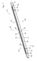
- the strip-shaped opener element 22 is shown in FIG. 7 in a perspective view. Further the strip-shaped opener element 22 together with the guide 21 is shown in different ways in FIGS. 8 to 11 .
- FIGS. 12 and 13 show the embodiments of FIGS. 3 and 4 in dismantled state.
- the strip-shaped opener element 22 is provided with an upper side 30, a lower side 31, a first lateral side 32 and an opposing second lateral side 33, wherein the first lateral side 32 and the second lateral side 33 extend between the upper side 30 and the lower side 31.
- the strip-shaped opener element 22 shown has two orthogonal lines of symmetry 82 and 83 diagrammatically indicated by broken lines in FIG. 7 .
- the strip-shaped opener element 22 has four operating surfaces 61, 62, 63, 64 and can be used in four different orientations.
- two operating surfaces of the opener element 22 are provided, more particularly two operating surfaces 61, 62 at the lateral side 32 and two operating surfaces 63, 64 at the lateral side 33.
- Each operating surface 61, 62, 63, 64 is adapted for cooperating with the gripper clamp of the gripper 2, 3 (shown in FIG. 2 ) for opening the gripper clamp of the gripper 2, 3.
- the operating surfaces 61, 62, 63, 64 are identical in design.
- the strip-shaped opener element 22 shown is provided at each lateral side 32, 33 with five surface parts 34, 35, 36 arranged at different angles with respect to a longitudinal direction and with four transition regions 37, 38 arranged between the surface parts 34, 35, 36.
- three surface parts 34, 35, 36 and the associated transition regions 37, 38 form an operating surface 61, 62; 63, 64, wherein a central surface part 34 is used by both operating surfaces 61, 62; 63, 64.
- a comparatively long straight central surface part 34 is provided.
- Such a central surface part 34 is advantageous for controlling an opening amount of the gripper clamp.
- surface parts 36 with a comparatively high angle of inclination are provided at the distal ends of the lateral side 32, 33.
- Such surface parts 36 are advantageous in order to open the gripper clamp quickly.
- surface parts 35 having a smaller angle of inclination than the surface parts 36 at the distal ends are provided, which is advantageous for stabilizing the movement of the gripper clamp during opening or closing.
- first coupling element 28 in the form of a groove is provided at the upper side 30 .
- second coupling element 79 (shown in FIG. 10 ), which is identical in construction to the first coupling element 28, hence, also in the form of a groove, is provided at the lower side 31 .
- the first coupling element 28 and the second coupling element 79 are arranged centrally in a direction perpendicular to the longitudinal direction at the upper side 30 and the lower side 31, respectively. Further, the first coupling element 28 and the second coupling element 79 are positioned in mirror symmetry to one another. Finally, the first coupling element 28 and the second coupling element 79 each have a plane of symmetry perpendicular to the upper side 30 and the lower side 31.
- a through hole 39 is provided for coupling the strip-shaped opener element 22 to the rod 25 shown in FIG. 8 .
- FIG. 9 is a top view of the guide 21 and the strip-shaped opener element 22.
- FIGS. 10 and 11 are cross sections along plane A-A and plane B-B in FIG. 9 , respectively.
- the guide 21 is provided with a counter element 27 in the form of a tongue protruding from an edge of the opening of the guiding channel 26 of the guide 21.
- the strip-shaped opener element 22 is mountable in the guiding channel 26 movably along the longitudinal direction of the guiding channel 26.
- the opener element 22 can present one of the four operating surfaces 61, 62, 63, 64 of the opener element 22 to contact the gripper clamp, for example for opening the gripper clamp 14 of the receiver gripper 3 shown in FIG. 5 .
- the first coupling element 28 this is the groove, provided on the upper side 30, or the second coupling element 79, this is the groove, provided on the lower side 31 is connected to the counter element 27, this is the tongue, provided at the guide 21 to form a tongue-and-groove connection for guiding the strip-shaped opener element 22 in the guiding channel 26 perpendicular to the longitudinal direction.
- the guide 21 comprises a main body 70 and a bottom element 71, which is detachable from the main body 70 for mounting and dismounting the strip-shaped opener element 22.
- the main body 70 and the bottom element 71 together form a U-shaped guiding channel 26.
- the counter element 27 is provided at the main body 70 at an edge of the opening of the guiding channel 26.
- a counter element 27 is provided at the bottom element 71, which is inserted in the groove provided at the coupling element 79 at a side of the strip-shaped opener element 22 facing the bottom element 71.
- the main body 70 is provided with a cut out 72 (shown in FIG. 9 ).
- the cut out 72 also separates the tongue provided as the counter element 27 at the main body 70 in two distinct tongue parts providing two distinct guiding areas 84 and 85 in the longitudinal direction of the guiding channel at two sides of the through hole 39.
- the guide 21 is provided with mounting blocks 86 having bores 42 for receiving pin-shaped elements 41 (shown in FIGS. 3 and 4 ).
- the guide 21 is arranged on a frame 60 of the weaving machine with the guiding channel 26 extending in parallel to a movement direction of the gripper 2, 3 (shown in FIG. 2 ).
- the gripper opener 20 comprises a support plate 29 attached using bolts 66 via a support block 47 to the frame 60.
- the guide 21 is fixeable to the frame 60 of the weaving machine via the support plate 29.
- the support plate 29 shown in FIGS. 3 and 4 is provided with two slotted holes 40, which are arranged at a slanted angle with respect to the longitudinal direction of the guiding channel 26.
- the guide 21 is fixed to the support plate 29 by means of two pin-shaped elements 41 each extending through one slotted hole 40 and are received in a bore 42 (shown in FIG. 6 ).
- the guide 21 is manually adjustable in position with respect to the support plate 29 in the movement direction of the gripper 2, 3 (shown in FIG. 2 ) and a transversal direction perpendicular to the movement direction of the gripper 2, 3 within the limits defined by the slotted holes 40.
- Both slotted holes 40 are arranged in parallel with respect to each other, hence, the longitudinal direction of the guiding channel 26 remains arranged in parallel to the movement direction of the gripper 2, 3 when adjusting a position of the guide 21.
- the guide 21 is fixed at the support plate 29 in a desired position.
- Butterfly nuts or wing nuts are provided at the pin-shaped elements 41 for fastening or loosening the pin-shaped elements 41.
- the butterfly nuts or wing nuts allow for a simple handling.
- the guide 21 and the strip-shaped opener element 22 are positioned underneath the support plate 29 between the frame 60 of the weaving machine and the support plate 29.
- the support plate 29 is provided with a removeable cover 43.
- the gripper opener 20 shown in FIGS. 3 and 4 further comprises a stop bar 44, which is arranged fixed in position on the frame 60 of the weaving machine.
- the stop bar 44 and the strip-shaped opener element 22 are arranged at the opposite sides of the movement path of the receiver gripper 3 (shown in FIG. 2 ), so that the receiver gripper 3 is guided sandwiched between the strip-shaped opener element 22 and the stop bar 44.
- the stop bar 44 limits an evasive movement of the receiver gripper 3 away from the strip-shaped opener element 22.
- a suction-unit 45 is provided.
- the suction-unit 45 is attached to the frame 60 in the region of the strip-shaped opener element 22.
- a blowing device 46 is provided to blow dust away from the gripper clamp.
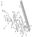
- FIGS. 14 and 15 are a perspective view of a second embodiment of a gripper opener 20, while FIGS. 16 and 17 show a dismantled state.
- the gripper opener 20 is similar to the gripper opener 20 shown in FIGS. 3 to 13 and the same reference numbers will be used for identical or like elements.
- the guide 21 is fixed to the support plate 29 by means of two pin-shaped elements 41 each extending through one associated slotted hole 40 provided at the support plate 29.
- the support plate 29 is attached to the frame 60 movable in position in the movement direction of the gripper 2, 3 (shown in FIG. 2 ).
- slotted holes 80, 81 are provided at the support plate 29 that extend after mounting the support plate 29 in parallel to the movement direction of the gripper 2, 3.
- a blowing device 46 can be provided on the support plate 29 in order to blow away dust from the gripper clamp.
- the suction-unit 45 is fixed via the support 67 to the frame 60 of the weaving machine. Hence, the suction-unit 45 is not moved with the support plate 29 when adjusting the position of the support plate 29.
- the support plate 29 is fixed via a support profile 48 to the frame 60.
- a stop bar 44 is fixed to the support profile 48, so that a gripper 2, 3 can be guided between the stop bar 44 and the strip-shaped opener element 22.
- the support plate 29 is also fixed to the frame 60 in a determined length position with respect to the frame 60 via at least one support block 49 and bolts 65.
- a gripper opener 20 is shown that cooperates with a gripper clamp 14 of the receiver gripper 3.
- the embodiments shown for the gripper opener 20 can of course also be applied for a gripper opener 5 that cooperates with a gripper clamp 14 of the bringer gripper 2.
Landscapes
- Engineering & Computer Science (AREA)
- Textile Engineering (AREA)
- Looms (AREA)
Claims (15)
- Un ouvre-pince pour ouvrir une pince à saisir (14) d'une pince (2, 3) d'une machine à tisser comprenant un élément d'ouverture (22) en forme de bande et un guide (21) avec un canal de guidage (26), dans lequel le guide (21) peut être disposé sur la machine à tisser avec le canal de guidage (26) s'étendant parallèlement à une direction de déplacement de la pince (2, 3), dans lequel l'élément d'ouverture (22) en forme de bande étant prévu d'un côté supérieur (30), un côté inférieur (31), un premier côté latéral (32) et un deuxième côté latéral (33), dans lequel le premier côté latéral (32) et le deuxième côté latéral (33) s'étendant entre le côté supérieur (30) et le côté inférieur (31), dans lequel l'élément d'ouverture (22) en forme de bande ayant une première surface de travail (61) prévue sur le premier côté latéral (32), dans lequel la première surface de travail (61) étant adaptée pour coopérer avec la pince à saisir (14) pour ouvrir la pince à saisir (14), et dans lequel l'élément d'ouverture (22) en forme de bande peut être disposé dans le canal de guidage (26) de manière mobile le long la direction longitudinale du canal de guidage (26) et présente la première surface de travail (61) de l'élément d'ouverture (22) pour entrer en contact avec la pince à saisir (14) pour ouvrir la pince à saisir (14), caractérisé en ce qu'un élément d'ouverture (22) en forme de bande est prévu sur le côté supérieur (30) d'un premier élément d'accouplement (28) et est prévu sur le côté inférieur (31) d'un deuxième élément d'accouplement (79) de construction identique au premier élément d'accouplement (28), dans lequel le premier élément d'accouplement (28) et le deuxième élément d'accouplement (79) étant disposés centralement dans une direction perpendiculaire à la direction longitudinale sur le côté supérieur (30) et le côté inférieur (31), respectivement, et positionnés en symétrie miroir l'un par rapport à l'autre, dans lequel le guide (21) est prévu d'au moins un contre-élément (27), et dans lequel l'un du premier élément d'accouplement (28) et du deuxième élément d'accouplement (79) forme une connexion à languette et rainure avec le au moins un contre-élément (27) pour guider l'élément d'ouverture (22) en forme de bande dans le canal de guidage (26) perpendiculairement à la direction longitudinale.
- L'ouvre-pince selon la revendication 1, caractérisé en ce que l'élément d'ouverture (22) en forme de bande a quatre surfaces de travail (61, 62, 63, 64), dans lequel deux surfaces de travail étant prévues sur chaque côté latéral (32, 33).
- L'ouvre-pince selon la revendication 1 ou 2, caractérisé en ce que l'élément d'ouverture (22) en forme de bande a deux lignes de symétrie orthogonales (82, 83).
- L'ouvre-pince selon la revendication 1, 2 ou 3, caractérisé en ce que le premier élément d'accouplement (28) et le deuxième élément d'accouplement (79) ont chacun la forme d'une rainure s'étendant dans la direction longitudinale, et le contre-élément (27) est une languette, en particulier une languette faisant saillie d'un bord d'une ouverture du canal de guidage (26).
- L'ouvre-pince selon la revendication 4, caractérisé en ce que le contre-élément (27) comprend deux parties de languette distinctes pour prévoir deux zones de guidage (84, 85) distinctes dans la direction longitudinale.
- L'ouvre-pince selon l'une quelconque des revendications 1 à 5, caractérisé en ce que l'ouvre-pince (5, 20) comprend un moteur d'entraînement (23) couplé de manière entraînante à l'élément d'ouverture (22) en forme de bande et utilisable pour déplacer l'élément d'ouverture (22) en forme de bande le long la direction longitudinale, dans lequel en particulier le moteur d'entraînement (23) étant couplé à l'élément d'ouverture (22) en forme de bande par l'intermédiaire d'une manivelle (24) et d'une tige (25).
- L'ouvre-pince selon l'une quelconque des revendications 1 à 6, caractérisé en ce que l'ouvre-pince (20) comprend une plaque de support (29), dans lequel le guide (21) étant fixable à un châssis (60) de la machine à tisser par l'intermédiaire de la plaque de support (29).
- L'ouvre-pince selon la revendication 7, caractérisé en ce que le guide (21) est disposé sur la plaque de support (29) réglable en position dans au moins la direction de déplacement de la pince (2, 3) et dans une direction transversale perpendiculaire à une direction de déplacement de la pince (2, 3), dans laquelle en particulier le guide (21) est disposé sur la plaque de support (29) réglable manuellement en position.
- L'ouvre-pince selon la revendication 8, caractérisé en ce que la connexion entre la plaque de support (29) et le guide (21) comprend au moins un trou fendu (40) et un élément en forme de goupille (41) s'étendant à travers le trou fendu (40).
- L'ouvre-pince selon la revendication 9, caractérisé en ce que le trou fendu (40) est diposé selon un angle incliné par rapport à la direction longitudinale du canal de guidage (26).
- L'ouvre-pince selon l'une quelconque des revendications 7 à 10, caractérisé en ce que, lorsque montés sur une machine à tisser le guide (21) et l'élément d'ouverture (22) en forme de bande sont positionnés sous la plaque de support (29) entre le châssis (60) de la machine à tisser et la plaque de support (29).
- L'ouvre-pince selon la revendication 11, caractérisé en ce que la plaque de support (29) est prévue d'un couvercle amovible (43) pour permettre l'accès au guide (21) et/ou à l'élément d'ouverture (22) en forme de bande positionné sous la plaque de support (29).
- Une machine à tisser comprenant une pince (2, 3) avec une pince à saisir (14) et un ouvre-pince (5, 20) selon l'une quelconque des revendications 1 à 12.
- La machine à tisser selon la revendication 13, caractérisée en ce qu'une unité d'aspiration (45) est montée sur le châssis (60) de la machine à tisser.
- La machine à tisser selon l'une quelconque des revendications 13 ou 14, caractérisée en ce qu'une barre d'arrêt (44) est prévue qui peut être disposée de manière fixe en position sur la machine à tisser, de sorte que la pince (2, 3) soit guidée en sandwich entre le guide (21) avec l'élément d'ouverture (22) en forme de bande et la barre d'arrêt (44).
Applications Claiming Priority (2)
| Application Number | Priority Date | Filing Date | Title |
|---|---|---|---|
| BE20150142A BE1023036A1 (nl) | 2015-05-07 | 2015-05-07 | Grijperopener voor een weefmachine |
| PCT/EP2016/059247 WO2016177601A1 (fr) | 2015-05-07 | 2016-04-26 | Dispositif d'ouverture de pince pour un métier à tisser |
Publications (2)
| Publication Number | Publication Date |
|---|---|
| EP3292235A1 EP3292235A1 (fr) | 2018-03-14 |
| EP3292235B1 true EP3292235B1 (fr) | 2019-06-05 |
Family
ID=54014445
Family Applications (1)
| Application Number | Title | Priority Date | Filing Date |
|---|---|---|---|
| EP16722083.9A Active EP3292235B1 (fr) | 2015-05-07 | 2016-04-26 | Dispositif d'ouverture de pince pour un métier à tisser |
Country Status (4)
| Country | Link |
|---|---|
| EP (1) | EP3292235B1 (fr) |
| CN (1) | CN107580638B (fr) |
| BE (1) | BE1023036A1 (fr) |
| WO (1) | WO2016177601A1 (fr) |
Families Citing this family (1)
| Publication number | Priority date | Publication date | Assignee | Title |
|---|---|---|---|---|
| EP4008818B1 (fr) * | 2020-12-07 | 2024-07-17 | Picanol | Procédé de réglage de course de déplacement d'une pince à fil et dispositif d'entrainement d'une pince à fil |
Family Cites Families (6)
| Publication number | Priority date | Publication date | Assignee | Title |
|---|---|---|---|---|
| DE3812966A1 (de) | 1987-10-02 | 1989-04-20 | Textilma Ag | Greiferwebmaschine |
| WO1997040218A1 (fr) * | 1996-04-19 | 1997-10-30 | Picanol N.V. | Dispositif pour ouvrir une pince de rapiere d'un metier mecanique |
| DE10114755A1 (de) | 2001-03-21 | 2002-09-26 | Picanol Nv | Nehmergreifer für eine Greiferwebmaschine |
| ITMI20030293U1 (it) | 2003-06-26 | 2004-12-27 | Promatech Spa | Apripinza motorizzato perfezionato |
| BE1018116A3 (nl) * | 2008-05-07 | 2010-05-04 | Picanol Nv | Nemergrijper, gevergrijper en inrichting voor een grijperweefmachine. |
| CN102978790A (zh) * | 2012-10-26 | 2013-03-20 | 苏州市德明纺织机械配件有限公司 | 一种递纬张开器 |
-
2015
- 2015-05-07 BE BE20150142A patent/BE1023036A1/nl not_active IP Right Cessation
-
2016
- 2016-04-26 EP EP16722083.9A patent/EP3292235B1/fr active Active
- 2016-04-26 WO PCT/EP2016/059247 patent/WO2016177601A1/fr not_active Ceased
- 2016-04-26 CN CN201680026539.1A patent/CN107580638B/zh active Active
Non-Patent Citations (1)
| Title |
|---|
| None * |
Also Published As
| Publication number | Publication date |
|---|---|
| CN107580638B (zh) | 2020-02-18 |
| EP3292235A1 (fr) | 2018-03-14 |
| CN107580638A (zh) | 2018-01-12 |
| WO2016177601A1 (fr) | 2016-11-10 |
| BE1023036A1 (nl) | 2016-11-09 |
Similar Documents
| Publication | Publication Date | Title |
|---|---|---|
| EP2449158B1 (fr) | Dispositif et procédé de saisie et d étirage des fils de trame dans une machine à tisser | |
| US20180291538A1 (en) | Weaving Machine with an Apparatus as well as Method for Holding, Feeding and Inserting Weft Threads in a Loom Shed | |
| WO2016177601A1 (fr) | Dispositif d'ouverture de pince pour un métier à tisser | |
| JP7017991B2 (ja) | グリッパ織機における疑似耳部の無い緯糸操作装置 | |
| EP2732086B1 (fr) | Dispositif et procédé de serrage d'un fil de trame | |
| KR20000005448A (ko) | 직조기 그리퍼의 그리퍼 고정부의 개방을 위한 장치2 | |
| EP0309700B1 (fr) | Métier à tisser à pinces | |
| US5092374A (en) | Guide and support devices for weft inserters in shuttleless looms | |
| CN102471957B (zh) | 织机的剑杆头 | |
| WO2007137544A1 (fr) | ProcÉdÉ et dispositif pour former une lisiÈre sur un mÉtier À tisser À pinces | |
| DE3224708C2 (de) | Einrichtung zur zwangsläufigen Betätigung der Klemmvorrichtung von Schußfadeneintragorganen an schützenlosen Webmaschinen | |
| BE1023036B1 (nl) | Grijperopener voor een weefmachine | |
| US3951179A (en) | Device for severing a thread in a textile machine | |
| CN1871387B (zh) | 用于选择纬纱和将纬纱喂给剑杆式引纬织机的剑杆的装置 | |
| DE10349645A1 (de) | Verfahren zum Auswählen und Zustellen von Schussfäden und Greiferwebmaschine mit einer Vorrichtung zum Auswählen und Zustellen von Schussfäden | |
| EP3155155B1 (fr) | Dispositif de formation de lisière pour un fil de trame | |
| EP4172393B1 (fr) | Métier à tisser à lances ayant un dispositif de guidage et procédé permettant de convertir un métier à tisser à lances | |
| DE1535249B1 (de) | Fachbildevorrichtung fuer webmaschinen | |
| EP2184389B1 (fr) | Procédé d'insertion de trame et dispositif d'insertion de trame d'une machine à tisser à lances | |
| EP1927691B1 (fr) | Dispositif et procédé de maintien de trame pour un métier à tisser à pince | |
| EP3507404B1 (fr) | Dispositif et procédé de saisie et d'étirage de fils de trame | |
| DD243304B1 (de) | Vorrichtung zur schussfadenpositionierung an greiferwebmachinen | |
| EP3433403B1 (fr) | Pince pour métier à tisser à pince | |
| DE1535249C (de) | Fachbildevorrichtung fur Webmaschinen | |
| JP2016040424A (ja) | 空気噴射式織機における緯糸規制装置 |
Legal Events
| Date | Code | Title | Description |
|---|---|---|---|
| STAA | Information on the status of an ep patent application or granted ep patent |
Free format text: STATUS: THE INTERNATIONAL PUBLICATION HAS BEEN MADE |
|
| PUAI | Public reference made under article 153(3) epc to a published international application that has entered the european phase |
Free format text: ORIGINAL CODE: 0009012 |
|
| STAA | Information on the status of an ep patent application or granted ep patent |
Free format text: STATUS: REQUEST FOR EXAMINATION WAS MADE |
|
| 17P | Request for examination filed |
Effective date: 20171107 |
|
| AK | Designated contracting states |
Kind code of ref document: A1 Designated state(s): AL AT BE BG CH CY CZ DE DK EE ES FI FR GB GR HR HU IE IS IT LI LT LU LV MC MK MT NL NO PL PT RO RS SE SI SK SM TR |
|
| AX | Request for extension of the european patent |
Extension state: BA ME |
|
| DAV | Request for validation of the european patent (deleted) | ||
| DAX | Request for extension of the european patent (deleted) | ||
| GRAP | Despatch of communication of intention to grant a patent |
Free format text: ORIGINAL CODE: EPIDOSNIGR1 |
|
| STAA | Information on the status of an ep patent application or granted ep patent |
Free format text: STATUS: GRANT OF PATENT IS INTENDED |
|
| INTG | Intention to grant announced |
Effective date: 20190129 |
|
| GRAS | Grant fee paid |
Free format text: ORIGINAL CODE: EPIDOSNIGR3 |
|
| GRAA | (expected) grant |
Free format text: ORIGINAL CODE: 0009210 |
|
| STAA | Information on the status of an ep patent application or granted ep patent |
Free format text: STATUS: THE PATENT HAS BEEN GRANTED |
|
| AK | Designated contracting states |
Kind code of ref document: B1 Designated state(s): AL AT BE BG CH CY CZ DE DK EE ES FI FR GB GR HR HU IE IS IT LI LT LU LV MC MK MT NL NO PL PT RO RS SE SI SK SM TR |
|
| REG | Reference to a national code |
Ref country code: GB Ref legal event code: FG4D |
|
| REG | Reference to a national code |
Ref country code: CH Ref legal event code: EP |
|
| REG | Reference to a national code |
Ref country code: AT Ref legal event code: REF Ref document number: 1140065 Country of ref document: AT Kind code of ref document: T Effective date: 20190615 |
|
| REG | Reference to a national code |
Ref country code: IE Ref legal event code: FG4D |
|
| REG | Reference to a national code |
Ref country code: DE Ref legal event code: R096 Ref document number: 602016014829 Country of ref document: DE |
|
| REG | Reference to a national code |
Ref country code: NL Ref legal event code: MP Effective date: 20190605 |
|
| REG | Reference to a national code |
Ref country code: LT Ref legal event code: MG4D |
|
| PG25 | Lapsed in a contracting state [announced via postgrant information from national office to epo] |
Ref country code: FI Free format text: LAPSE BECAUSE OF FAILURE TO SUBMIT A TRANSLATION OF THE DESCRIPTION OR TO PAY THE FEE WITHIN THE PRESCRIBED TIME-LIMIT Effective date: 20190605 Ref country code: AL Free format text: LAPSE BECAUSE OF FAILURE TO SUBMIT A TRANSLATION OF THE DESCRIPTION OR TO PAY THE FEE WITHIN THE PRESCRIBED TIME-LIMIT Effective date: 20190605 Ref country code: NO Free format text: LAPSE BECAUSE OF FAILURE TO SUBMIT A TRANSLATION OF THE DESCRIPTION OR TO PAY THE FEE WITHIN THE PRESCRIBED TIME-LIMIT Effective date: 20190905 Ref country code: HR Free format text: LAPSE BECAUSE OF FAILURE TO SUBMIT A TRANSLATION OF THE DESCRIPTION OR TO PAY THE FEE WITHIN THE PRESCRIBED TIME-LIMIT Effective date: 20190605 Ref country code: SE Free format text: LAPSE BECAUSE OF FAILURE TO SUBMIT A TRANSLATION OF THE DESCRIPTION OR TO PAY THE FEE WITHIN THE PRESCRIBED TIME-LIMIT Effective date: 20190605 Ref country code: LT Free format text: LAPSE BECAUSE OF FAILURE TO SUBMIT A TRANSLATION OF THE DESCRIPTION OR TO PAY THE FEE WITHIN THE PRESCRIBED TIME-LIMIT Effective date: 20190605 Ref country code: ES Free format text: LAPSE BECAUSE OF FAILURE TO SUBMIT A TRANSLATION OF THE DESCRIPTION OR TO PAY THE FEE WITHIN THE PRESCRIBED TIME-LIMIT Effective date: 20190605 |
|
| PG25 | Lapsed in a contracting state [announced via postgrant information from national office to epo] |
Ref country code: LV Free format text: LAPSE BECAUSE OF FAILURE TO SUBMIT A TRANSLATION OF THE DESCRIPTION OR TO PAY THE FEE WITHIN THE PRESCRIBED TIME-LIMIT Effective date: 20190605 Ref country code: BG Free format text: LAPSE BECAUSE OF FAILURE TO SUBMIT A TRANSLATION OF THE DESCRIPTION OR TO PAY THE FEE WITHIN THE PRESCRIBED TIME-LIMIT Effective date: 20190905 Ref country code: RS Free format text: LAPSE BECAUSE OF FAILURE TO SUBMIT A TRANSLATION OF THE DESCRIPTION OR TO PAY THE FEE WITHIN THE PRESCRIBED TIME-LIMIT Effective date: 20190605 Ref country code: GR Free format text: LAPSE BECAUSE OF FAILURE TO SUBMIT A TRANSLATION OF THE DESCRIPTION OR TO PAY THE FEE WITHIN THE PRESCRIBED TIME-LIMIT Effective date: 20190906 |
|
| REG | Reference to a national code |
Ref country code: AT Ref legal event code: MK05 Ref document number: 1140065 Country of ref document: AT Kind code of ref document: T Effective date: 20190605 |
|
| PG25 | Lapsed in a contracting state [announced via postgrant information from national office to epo] |
Ref country code: PT Free format text: LAPSE BECAUSE OF FAILURE TO SUBMIT A TRANSLATION OF THE DESCRIPTION OR TO PAY THE FEE WITHIN THE PRESCRIBED TIME-LIMIT Effective date: 20191007 Ref country code: SK Free format text: LAPSE BECAUSE OF FAILURE TO SUBMIT A TRANSLATION OF THE DESCRIPTION OR TO PAY THE FEE WITHIN THE PRESCRIBED TIME-LIMIT Effective date: 20190605 Ref country code: EE Free format text: LAPSE BECAUSE OF FAILURE TO SUBMIT A TRANSLATION OF THE DESCRIPTION OR TO PAY THE FEE WITHIN THE PRESCRIBED TIME-LIMIT Effective date: 20190605 Ref country code: AT Free format text: LAPSE BECAUSE OF FAILURE TO SUBMIT A TRANSLATION OF THE DESCRIPTION OR TO PAY THE FEE WITHIN THE PRESCRIBED TIME-LIMIT Effective date: 20190605 Ref country code: RO Free format text: LAPSE BECAUSE OF FAILURE TO SUBMIT A TRANSLATION OF THE DESCRIPTION OR TO PAY THE FEE WITHIN THE PRESCRIBED TIME-LIMIT Effective date: 20190605 Ref country code: CZ Free format text: LAPSE BECAUSE OF FAILURE TO SUBMIT A TRANSLATION OF THE DESCRIPTION OR TO PAY THE FEE WITHIN THE PRESCRIBED TIME-LIMIT Effective date: 20190605 Ref country code: NL Free format text: LAPSE BECAUSE OF FAILURE TO SUBMIT A TRANSLATION OF THE DESCRIPTION OR TO PAY THE FEE WITHIN THE PRESCRIBED TIME-LIMIT Effective date: 20190605 |
|
| PG25 | Lapsed in a contracting state [announced via postgrant information from national office to epo] |
Ref country code: IS Free format text: LAPSE BECAUSE OF FAILURE TO SUBMIT A TRANSLATION OF THE DESCRIPTION OR TO PAY THE FEE WITHIN THE PRESCRIBED TIME-LIMIT Effective date: 20191005 Ref country code: SM Free format text: LAPSE BECAUSE OF FAILURE TO SUBMIT A TRANSLATION OF THE DESCRIPTION OR TO PAY THE FEE WITHIN THE PRESCRIBED TIME-LIMIT Effective date: 20190605 |
|
| REG | Reference to a national code |
Ref country code: DE Ref legal event code: R097 Ref document number: 602016014829 Country of ref document: DE |
|
| PLBE | No opposition filed within time limit |
Free format text: ORIGINAL CODE: 0009261 |
|
| STAA | Information on the status of an ep patent application or granted ep patent |
Free format text: STATUS: NO OPPOSITION FILED WITHIN TIME LIMIT |
|
| PG25 | Lapsed in a contracting state [announced via postgrant information from national office to epo] |
Ref country code: PL Free format text: LAPSE BECAUSE OF FAILURE TO SUBMIT A TRANSLATION OF THE DESCRIPTION OR TO PAY THE FEE WITHIN THE PRESCRIBED TIME-LIMIT Effective date: 20190605 Ref country code: DK Free format text: LAPSE BECAUSE OF FAILURE TO SUBMIT A TRANSLATION OF THE DESCRIPTION OR TO PAY THE FEE WITHIN THE PRESCRIBED TIME-LIMIT Effective date: 20190605 |
|
| 26N | No opposition filed |
Effective date: 20200306 |
|
| PG25 | Lapsed in a contracting state [announced via postgrant information from national office to epo] |
Ref country code: SI Free format text: LAPSE BECAUSE OF FAILURE TO SUBMIT A TRANSLATION OF THE DESCRIPTION OR TO PAY THE FEE WITHIN THE PRESCRIBED TIME-LIMIT Effective date: 20190605 |
|
| PG25 | Lapsed in a contracting state [announced via postgrant information from national office to epo] |
Ref country code: MC Free format text: LAPSE BECAUSE OF FAILURE TO SUBMIT A TRANSLATION OF THE DESCRIPTION OR TO PAY THE FEE WITHIN THE PRESCRIBED TIME-LIMIT Effective date: 20190605 |
|
| REG | Reference to a national code |
Ref country code: CH Ref legal event code: PL |
|
| PG25 | Lapsed in a contracting state [announced via postgrant information from national office to epo] |
Ref country code: LU Free format text: LAPSE BECAUSE OF NON-PAYMENT OF DUE FEES Effective date: 20200426 Ref country code: FR Free format text: LAPSE BECAUSE OF NON-PAYMENT OF DUE FEES Effective date: 20200430 Ref country code: LI Free format text: LAPSE BECAUSE OF NON-PAYMENT OF DUE FEES Effective date: 20200430 Ref country code: CH Free format text: LAPSE BECAUSE OF NON-PAYMENT OF DUE FEES Effective date: 20200430 |
|
| GBPC | Gb: european patent ceased through non-payment of renewal fee |
Effective date: 20200426 |
|
| PG25 | Lapsed in a contracting state [announced via postgrant information from national office to epo] |
Ref country code: GB Free format text: LAPSE BECAUSE OF NON-PAYMENT OF DUE FEES Effective date: 20200426 Ref country code: IE Free format text: LAPSE BECAUSE OF NON-PAYMENT OF DUE FEES Effective date: 20200426 |
|
| PG25 | Lapsed in a contracting state [announced via postgrant information from national office to epo] |
Ref country code: MT Free format text: LAPSE BECAUSE OF FAILURE TO SUBMIT A TRANSLATION OF THE DESCRIPTION OR TO PAY THE FEE WITHIN THE PRESCRIBED TIME-LIMIT Effective date: 20190605 Ref country code: CY Free format text: LAPSE BECAUSE OF FAILURE TO SUBMIT A TRANSLATION OF THE DESCRIPTION OR TO PAY THE FEE WITHIN THE PRESCRIBED TIME-LIMIT Effective date: 20190605 |
|
| PG25 | Lapsed in a contracting state [announced via postgrant information from national office to epo] |
Ref country code: MK Free format text: LAPSE BECAUSE OF FAILURE TO SUBMIT A TRANSLATION OF THE DESCRIPTION OR TO PAY THE FEE WITHIN THE PRESCRIBED TIME-LIMIT Effective date: 20190605 |
|
| P01 | Opt-out of the competence of the unified patent court (upc) registered |
Effective date: 20230519 |
|
| PGFP | Annual fee paid to national office [announced via postgrant information from national office to epo] |
Ref country code: DE Payment date: 20250422 Year of fee payment: 10 |
|
| PGFP | Annual fee paid to national office [announced via postgrant information from national office to epo] |
Ref country code: IT Payment date: 20250430 Year of fee payment: 10 |
|
| PGFP | Annual fee paid to national office [announced via postgrant information from national office to epo] |
Ref country code: TR Payment date: 20250418 Year of fee payment: 10 |
|
| PGFP | Annual fee paid to national office [announced via postgrant information from national office to epo] |
Ref country code: BE Payment date: 20260210 Year of fee payment: 11 |