EP3292362B1 - Kühlvorrichtungen mit temperaturgesteuerten containersystemen - Google Patents
Kühlvorrichtungen mit temperaturgesteuerten containersystemen Download PDFInfo
- Publication number
- EP3292362B1 EP3292362B1 EP16789968.1A EP16789968A EP3292362B1 EP 3292362 B1 EP3292362 B1 EP 3292362B1 EP 16789968 A EP16789968 A EP 16789968A EP 3292362 B1 EP3292362 B1 EP 3292362B1
- Authority
- EP
- European Patent Office
- Prior art keywords
- liquid
- refrigeration device
- refrigeration
- impermeable container
- evaporator
- Prior art date
- Legal status (The legal status is an assumption and is not a legal conclusion. Google has not performed a legal analysis and makes no representation as to the accuracy of the status listed.)
- Active
Links
Images




Classifications
-
- F—MECHANICAL ENGINEERING; LIGHTING; HEATING; WEAPONS; BLASTING
- F25—REFRIGERATION OR COOLING; COMBINED HEATING AND REFRIGERATION SYSTEMS; HEAT PUMP SYSTEMS; MANUFACTURE OR STORAGE OF ICE; LIQUEFACTION SOLIDIFICATION OF GASES
- F25D—REFRIGERATORS; COLD ROOMS; ICE-BOXES; COOLING OR FREEZING APPARATUS NOT OTHERWISE PROVIDED FOR
- F25D16/00—Devices using a combination of a cooling mode associated with refrigerating machinery with a cooling mode not associated with refrigerating machinery
-
- F—MECHANICAL ENGINEERING; LIGHTING; HEATING; WEAPONS; BLASTING
- F25—REFRIGERATION OR COOLING; COMBINED HEATING AND REFRIGERATION SYSTEMS; HEAT PUMP SYSTEMS; MANUFACTURE OR STORAGE OF ICE; LIQUEFACTION SOLIDIFICATION OF GASES
- F25D—REFRIGERATORS; COLD ROOMS; ICE-BOXES; COOLING OR FREEZING APPARATUS NOT OTHERWISE PROVIDED FOR
- F25D11/00—Self-contained movable devices, e.g. domestic refrigerators
- F25D11/006—Self-contained movable devices, e.g. domestic refrigerators with cold storage accumulators
-
- F—MECHANICAL ENGINEERING; LIGHTING; HEATING; WEAPONS; BLASTING
- F25—REFRIGERATION OR COOLING; COMBINED HEATING AND REFRIGERATION SYSTEMS; HEAT PUMP SYSTEMS; MANUFACTURE OR STORAGE OF ICE; LIQUEFACTION SOLIDIFICATION OF GASES
- F25B—REFRIGERATION MACHINES, PLANTS OR SYSTEMS; COMBINED HEATING AND REFRIGERATION SYSTEMS; HEAT PUMP SYSTEMS
- F25B23/00—Machines, plants or systems, with a single mode of operation not covered by groups F25B1/00 - F25B21/00, e.g. using selective radiation effect
- F25B23/006—Machines, plants or systems, with a single mode of operation not covered by groups F25B1/00 - F25B21/00, e.g. using selective radiation effect boiling cooling systems
Definitions
- the present invention relates to a refrigeration device.
- JP H06 194025A discloses a cold storage tank structure of a cold storage type refrigerator.
- JP H 06 194025 does not disclose at least one temperature sensor positioned within a liquid-impermeable container between one or more walls of the container and a set of evaporator coils, or a controller operably attached to at least one active refrigeration unit and to the temperature sensor, or a compressor attached to the set of evaporator coils, wherein the controller is positioned between the compressor and a wire connection to an electric source, or that the controller is configured to send control signals to the compressor in response to data received from the temperature sensor.
- JP H08 240372A discloses a heat storage type refrigerator which uses a heat storage material to cool its interior.
- US4918936A discloses a refrigerating cycle including a cold-accumulation material to be cooled.
- EP2549210A2 discloses a refrigerator with a thermal storage device.
- Refrigeration devices are described herein.
- refrigeration devices are of a size, shape and configuration to be used as a domestic refrigerator device.
- refrigeration devices are of a size, shape and configuration for use as a domestic refrigerator appliance.
- refrigeration devices are of a size, shape and configuration for use as a commercial refrigerator device.
- refrigeration devices are of a size, shape and configuration for use as a medical refrigerator device, such as in a clinic or health outpost in a region with uncertain or intermittent power supply.
- the refrigeration devices described herein are configured to provide ongoing temperature control to at least one storage region within each refrigeration device.
- the refrigeration devices described herein are designed to provide ongoing temperature control to at least one storage region within the refrigeration devices even in times when a refrigeration device is not able to operate based on the usual power supply, for example during power outages.
- the refrigeration devices described herein will be useful in locations with intermittent or variable power supply to refrigeration devices.
- refrigeration devices can be configured to maintain the internal storage region or regions within a predetermined temperature range indefinitely while the refrigeration device has access to electrical power approximately 10% of the time on average.
- refrigeration devices can be configured to maintain the internal storage region or regions within a predetermined temperature range indefinitely while the refrigeration device has access to electrical power approximately 5% of the time on average.
- refrigeration devices can be configured to maintain the internal storage region or regions within a predetermined temperature range indefinitely while the refrigeration device has access to electrical power approximately 1% of the time on average.
- refrigeration devices can be configured to maintain the internal storage region or regions within a predetermined temperature range for at least 30 hours.
- refrigeration devices can be configured to maintain the internal storage region or regions within a predetermined temperature range for at least 50 hours.
- refrigeration devices can be configured to maintain the internal storage region or regions within a predetermined temperature range for at least 70 hours.
- refrigeration devices can be configured to maintain the internal storage region or regions within a predetermined temperature range for at least 90 hours.
- refrigeration devices can be configured to maintain the internal storage region or regions within a predetermined temperature range for at least 110 hours.
- refrigeration devices can be configured to maintain the internal storage region or regions within a predetermined temperature range for at least 130 hours.
- refrigeration devices can be configured to maintain the internal storage region or regions within a predetermined temperature range for at least 150 hours.
- refrigeration devices can be configured to maintain the internal storage region or regions within a predetermined temperature range for at least 170 hours.
- Items that are sensitive to temperature extremes can be stored within the storage region or regions of refrigeration devices in order to maintain the items within a predetermined temperature range for extended periods, even when power supply to the refrigeration device is interrupted.
- a refrigeration device that is unable to obtain power is configured to maintain the temperature of its internal storage region or regions within a predetermined temperature range for an extended period of time when the ambient external temperature is between -10°C and 43°C.
- a refrigeration device that is unable to obtain power is configured to maintain the temperature of its internal storage region or regions within a predetermined temperature range for a period of time when the ambient external temperature is between 25°C and 43°C.
- a refrigeration device that is unable to obtain power is configured to maintain the temperature of its internal storage region or regions within a predetermined temperature range for a period of time when the ambient external temperature is between 35°C and 43°C.
- a refrigeration device that is unable to obtain power is configured to maintain the temperature of its internal storage region or regions within a predetermined temperature range for at least one week when the ambient external temperature is between -35°C and 43°C.
- a refrigeration device that is unable to obtain power is configured to maintain the temperature of its internal storage region or regions within a predetermined temperature range for at least two weeks when the ambient external temperature is between -35°C and 43°C.
- a refrigeration device that is unable to obtain power is configured to maintain the temperature of its internal storage region or regions within a predetermined temperature range for at least 30 days when the ambient external temperature is between -35°C and 43°C.
- a refrigeration device that is unable to obtain power is configured to maintain the temperature of its internal storage region or regions within a predetermined temperature range for a period of time when the ambient external temperature is below -10°C.
- a "refrigeration device” refers to a device with an internal storage region that utilizes an external power source at least part of the time and is configured to consistently store material at a temperature below ambient temperature for a period of time.
- a refrigeration device can include two internal storage regions.
- a refrigeration device can include more than two internal storage regions.
- a refrigeration device can include two or more internal storage regions, each of the storage regions configured to maintain an internal temperature within a different temperature range.
- refrigeration devices include an active refrigeration system.
- a refrigeration device can be electrically powered from a municipal power supply.
- a refrigeration device can be powered from a solar power system.
- a refrigeration device can be powered from a battery.
- a refrigeration device can be powered from a generator, such as a diesel power generator.
- a refrigeration device can be a refrigerator. Refrigerators are generally calibrated to hold internally stored items in a predetermined temperature range above zero but less than potential ambient temperatures. Refrigerators can, for example, be designed to maintain internal temperatures between 1°C and 4°C.
- a refrigeration device can be a standard freezer. Freezers are generally calibrated to hold internally stored items in a temperature range below zero but above cryogenic temperatures. Freezers can, for example, be designed to maintain internal temperatures between -23°C and -17°C, or can, for example, be designed to maintain internal temperatures between -18°C and -15°C.
- a refrigeration device can include both a refrigerator compartment and a freezer compartment. For example, some refrigeration devices include a first internal storage region that consistently maintains refrigerator temperature ranges and a second internal storage region that consistently maintains freezer temperature ranges.
- a refrigeration device can be configured to maintain the interior storage region of the refrigeration device within a predetermined temperature range.
- a "predetermined temperature range,” as used herein, refers to a range of temperatures that have been predetermined to be desirable for an interior storage region of a particular refrigeration device in use.
- a predetermined temperature range is the stable temperature range that an interior storage region of a refrigeration device maintains temperature within during use of the refrigeration device.
- a refrigeration device can be configured to maintain an interior storage region of the refrigeration device within a predetermined temperature range of approximately 2°C to 8°C.
- a refrigeration device can be configured to maintain an interior storage region of the refrigeration device within a predetermined temperature range of approximately 1°C to 9°C.
- a refrigeration device can be configured to maintain an interior storage region of the refrigeration device within a predetermined temperature range of approximately -15°C to -25°C.
- a refrigeration device can be configured to maintain an interior storage region of the refrigeration device within a predetermined temperature range of approximately -5°C to - 10°C.
- a refrigeration device can be configured to maintain an interior storage region of the refrigeration device within the predetermined temperature range for at least 50 hours when power is unavailable to the refrigeration device.
- a refrigeration device can be configured to maintain an interior storage region of the refrigeration device within the predetermined temperature range for at least 100 hours when power is unavailable to the refrigeration device.
- a refrigeration device can be configured to maintain an interior storage region of the refrigeration device within the predetermined temperature range for at least 150 hours when power is unavailable to the refrigeration device.
- a refrigeration device can be configured to maintain an interior storage region of the refrigeration device within the predetermined temperature range for at least 200 hours when power is unavailable to the refrigeration device.
- a refrigeration device can be configured to passively maintain its interior storage region or regions within a predetermined temperature range for an extended period of time when power is unavailable to the refrigeration device.
- a refrigeration device can be configured to maintain its interior storage region or regions within a predetermined temperature range for an extended period of time when minimal electric power is available to the refrigeration device.
- a refrigeration device can be configured to maintain its interior storage region or regions within a predetermined temperature range for an extended period of time when low-voltage electric power is available to the refrigeration device.
- a refrigeration device can be configured to maintain its interior storage region or regions within a predetermined temperature range for an extended period of time when variable electric power is available to the refrigeration device.
- the refrigeration device can include a variable power control system.
- the refrigeration device can include a battery. The refrigeration device operates passively in the absence of power, and does not include a battery.
- Figure 1 depicts a refrigeration device 100 that includes a single storage region internal to the refrigeration device.
- a single door 120 substantially opens the single storage region of the refrigeration device to outside users of the device.
- a user of the device can use a handle 125 to open the door 120.
- the refrigeration device 100 is depicted with the front face of an exterior wall of a shell 110 visible.
- There is a single door that provides a user access to multiple storage regions within the refrigeration device, such as a first storage region maintained within a first temperature range and a second storage region maintained within a second temperature range.
- the refrigeration device 100 depicted in Figure 1 can include a top door 140 reversibly affixed to the upper surface of the refrigeration device 100 with a latch 150.
- a top door 140 can, for example, be configured to permit access to a liquid-impermeable container located within the refrigeration device 100, the liquid-impermeable container positioned adj acent to an inner surface of the top door 140.
- a refrigeration device can be configured to operate from an electrical power supply, such as a municipal power supply or solar electrical power system.
- the refrigeration device 100 shown in Figure 1 can include a power cord 130 to connect with the electrical power supply.
- a refrigeration device can include a shell forming an exterior of the refrigeration device around the liquid-impermeable container, the at least one set of evaporator coils, the thermal conductor and the storage region.
- a refrigeration device can include a shell surrounding the liquid-impermeable container, the set of evaporator coils, the one or more walls substantially forming a storage region and the heat transfer system, and a door within the shell, the door positioned to reversibly permit a user to access the storage region.
- a shell 110 surrounds the exterior of the visible components of the refrigeration device.
- a shell can be fabricated from a rigid material, for example a fiberglass material or a metal such as stainless steel or aluminum.
- a refrigeration device can include insulation positioned within the shell.
- a refrigeration device can include insulation positioned adjacent to an exterior surface of the storage region.
- the insulation can be of a size and shape to reversibly mate with the external surfaces of the walls of the liquid-impermeable container and the exterior walls substantially forming a storage region.
- the insulation is of sufficient thickness, quality and composition to reduce the heat leak from the storage region to the level where it is substantially balanced by the heat transfer through the heat transfer system and for the expected use scenarios.
- the refrigeration device and insulation can have a heat leak of approximately 30 W.
- the refrigeration device and insulation can have a heat leak of approximately 25 W.
- the refrigeration device and insulation can have a heat leak of approximately 20 W.
- the refrigeration device and insulation can have a heat leak of approximately 15 W.
- the refrigeration device and insulation can have a heat leak of approximately 10 W.
- the insulation can be fabricated from a foam insulation.
- the insulation can be fabricated from vacuum insulated panels ("VIP").
- Figure 2 depicts a refrigeration device 100 that can include dual storage regions internal to the refrigeration device.
- the refrigeration device 100 is depicted with the front face of an exterior wall 110 visible.
- a first door 120 can substantially open the first storage region of the refrigeration device to outside users of the device.
- a user of the device can use a handle 125 to open the first door 120.
- a first storage region can be configured to maintain an internal temperature ten degrees or less above freezing ( i.e. 0 degrees Centigrade).
- a first storage region can be configured to maintain, for example, an internal temperature in a range between approximately 0 degrees Centigrade and approximately 10 degrees Centigrade.
- a first storage region can be configured to maintain, for example, an internal temperature in a range between approximately 1 degree Centigrade and approximately 9 degrees Centigrade.
- a first storage region can be configured to maintain, for example, an internal temperature in a range between approximately 2 degrees Centigrade and approximately 8 degrees Centigrade.
- the refrigeration device shown in Figure 2 also includes a second door 200 with a handle 210 to provide access to a user to a second storage region interior to the refrigeration device.
- a second storage region can be configured to maintain an internal temperature twenty degrees or more below freezing.
- a second storage region can be configured to maintain, for example, an internal temperature in a range between approximately -15 degrees Centigrade and approximately -20 degrees Centigrade.
- a second storage region can be configured to maintain, for example, an internal temperature in a range between approximately -10 degrees Centigrade and approximately -5 degrees Centigrade.
- a second storage region can be configured to maintain, for example, an internal temperature of approximately 0 degrees Centigrade.
- a second storage region can be configured for the storage and freezing of one or more phase change material freezer containers, such as medical-use ice packs.
- the refrigeration device 100 shown in Figure 2 can include a top door 140 reversibly affixed to the upper surface of the refrigeration device 100 with a latch 150.
- the top door 140 can, for example, be configured to allow a user to access a liquid-impermeable container within the refrigeration device 100, the liquid-impermeable container located adjacent to an inner surface of the top door 140.
- Some refrigeration devices can be configured to operate from an electrical power supply, such as a municipal power supply or solar electrical power system.
- the refrigeration device 100 shown in Figure 2 includes a power cord 130 to connect with the electrical power supply.
- Figure 3 depicts a refrigeration device 100 including a liquid-impermeable container 300 configured to hold phase change material internal to the refrigeration device 100 and a storage region 310.
- a refrigeration device 100 including a liquid-impermeable container 300 configured to hold phase change material internal to the refrigeration device 100 and a storage region 310.
- features of the refrigeration device 100 such as a shell, door(s) and/ or a cover ( see , e.g. Figures 1 and 2 ) to the refrigeration device 100 are not depicted in Figure 3 , however the refrigeration device can include these and other features.
- a liquid-impermeable container can also be vapor-impermeable. As illustrated in Figure 3 , the liquid-impermeable container 300 is positioned above the storage region 310 within the refrigeration device 100.
- a liquid-impermeable container can include: an aperture of a size, shape and position to permit the set of evaporator coils to traverse the aperture; and a liquid-impermeable seal between a surface of the aperture and a surface of the set of evaporator coils.
- a liquid-impermeable container can include: an aperture of a size, shape and position to permit the set of evaporator coils to traverse the aperture; and a vapor-impermeable seal between a surface of the aperture and a surface of the set of evaporator coils.
- One or more walls substantially form a liquid-impermeable container, and the liquid-impermeable container is configured to hold phase change material internal to a refrigeration device.
- the liquid-impermeable container 300 illustrated is fabricated from a plurality of planar walls 320 forming a cuboid structure with solid walls and a bottom, and an aperture at the topmost surface forming an open top section.
- the plurality of planar walls 320 of the liquid-impermeable container 300 are sealed at their edges at approximately right angles with liquid-impermeable seals.
- the one or more walls substantially forming a liquid-impermeable container can include a plurality of layers and the condenser is positioned adjacent to a surface of at least one of the plurality of layers.
- the one or more walls substantially forming the liquid-impermeable container can include a plurality of layers wherein at least one of the one or more layers includes non-planar regions to form multiple sides of the liquid-impermeable container.
- the one or more walls substantially forming a liquid-impermeable container can include an aperture of a position, size and shape to form an access opening.
- an access opening can be of a size, shape and position to permit a user to inspect, refresh and/or renew the interior of the liquid-impermeable container and its contents.
- the one or more walls substantially forming a liquid-impermeable container can include an aperture of a position, size and shape to reversibly mate with a door.
- Some refrigeration devices include an access lid within a top surface of the liquid-impermeable container, the access lid configured for a user to access an interior of the liquid-impermeable container.
- phase change material is positioned within the liquid-impermeable container.
- a phase change material can be included within the liquid-impermeable container 300 in a position 305 surrounding the set of refrigeration coils 330.
- a "phase-change material,” as used herein, is a material with a high latent heat, which is capable of storing and releasing heat energy while changing physical phase. The selection of a phase change material depends on considerations including the latent heat for the material, the melting point for the material, the boiling point for the material, the volume of material required to store a predetermined amount of heat energy, the toxicity of the material, the cost of the material, and the flammability of the material.
- a phase-change material can be a solid, a liquid, a semi-solid or a gas during use.
- a phase-change material can include water, methanol, ethanol, a sodium polyacrylate/polysaccharide material or a salt hydrate.
- a phase change material including a majority of the volume as pure water/ice is preferred due to the physical property of pure water/ice having a melting point of 0°C.
- a phase change material including a majority of the volume as salt water/salt ice is preferred as the melting point of salt ice can be calibrated to below 0°C based on the salt molarity and content within the salt water/salt ice.
- a phase change material is configured to freeze at below -20°C.
- a phase change material is configured to freeze at a point between 1°C and 3°C.
- a phase change material can be in a liquid form at ambient temperatures ( e . g . 25°C).
- the refrigeration device 100 includes an active refrigeration unit including a set of evaporator coils 330.
- the set of evaporator coils 330 is positioned within an interior of the liquid-impermeable container 300.
- a refrigeration device can include two active refrigeration units, each including its own set of evaporator coils. Both sets of evaporator coils can, for example, be positioned within a single liquid-impermeable container within the refrigeration device. Each set of evaporator coils can, for example, be positioned within two liquid-impermeable containers within a single refrigeration device, and each set of refrigeration coils can be independently controlled by a single controller attached to each of the active refrigeration units.
- a refrigeration device can include a single active refrigeration unit including two sets of evaporator coils.
- Each set of evaporator coils can, for example, be positioned within two liquid-impermeable containers within a single refrigeration device, and each set of refrigeration coils can be independently controlled, such as with a reversibly controlled thermal control device, such as a valve system.
- a refrigeration device can include an active refrigeration unit that includes an active refrigeration system.
- a refrigeration device can include an active refrigeration unit that includes an electrically powered compression system.
- the refrigeration device includes an active refrigeration unit that includes a compressor. As shown in Figure 3 a compressor 335 is operably attached to the set of evaporator coils 330.
- the refrigeration device includes a controller. As illustrated in Figure 3 a controller 380 is positioned between the compressor 335 and a wire connection 395 to an electric source.
- a controller can include an electronic controller with circuitry configured to send control signals to the compressor and/or other features of the device.
- a controller can include an electronic controller with circuitry configured to receive signals from the compressor and/or other features of the device such as sensors or monitors.
- a controller can include a wireless signal generator, such as a cellular radio transmitter.
- a controller can include circuitry for data acquisition, such as data from one or more sensors, and/or a power monitor.
- a controller can include circuitry for temperature control, such as by sending a control signal to an operably attached compressor.
- a controller can include circuitry for temperature display, such as by sending a control signal to an operably attached display unit.
- a controller can include: circuitry for receiving data from one or more sensors; circuitry for evaluating received data for one or more predetermined set point values; circuitry to send a control signal in response to a detected value that meets one or more predetermined set point values; and circuitry to transmit the received data externally to the refrigeration device.
- a controller can be configured to: receive data from multiple temperature sensors; to evaluate the received data relative to predetermined maximum and/or minimum values; to send a control signal in response to a detected maximum and/or minimum value; and to send a signal including the received data to a monitoring system.
- a refrigeration device can be expected to be used in locations with intermittent power availability, such as due to periodic failure of a municipal power grid or unavailability of solar power.
- a refrigeration device can include, for example, a battery affixed to the at least one active refrigeration unit.
- a refrigeration device can be configured to utilize battery power to run the active refrigeration unit conditionally, for example if there is a lack of power for a predetermined period of time (e.g. 2 days, 3 days, or 4 days).
- a refrigeration device can be configured to utilize battery power to run the active refrigeration unit conditionally, for example if a temperature sensor positioned within the refrigeration device detects a temperature above a predetermined threshold level.
- a refrigeration device can be expected to be used in locations with variable power availability, such as a power supply of varying voltages over time.
- a refrigeration device can include, for example, a variable power control system attached to the at least one active refrigeration unit.
- a variable power control system can be designed to accept power from different sources, such as 120, 230 VAC, and 12 to 24 VDC.
- a variable power control system can include a power converter.
- the power converter can, for example, be configured to convert AC input power to DC.
- the power converter can, for example, be configured to convert variable AC input power to 220 V AC.
- a variable power control system can include an automatic voltage regulator.
- a refrigeration device configured for use in a location with a poorly functioning electrical grid can be configured to accept power in the range of 90 V AC to 250 V AC and covert the input to a steady 220 V AC with an integral automatic voltage regulator.
- a refrigeration device can include one or more voltage and/or current sensors positioned and configured to detect the power supply to the refrigeration device. The sensors can be attached to a controller, and/or a transmitter unit, and/or a memory unit.
- a refrigeration device can include a voltage stabilizer.
- a refrigeration device can include a power conditioning unit.
- a refrigeration device can be configured to permit operation from a power grid when such is available, and from an alternate power source, such as a photovoltaic unit, at other times.
- a refrigeration device can be configured to permit operation from a power grid in response to input from a user, and from an alternate power source, such as a photovoltaic unit, in response to other input, such as the availability of solar energy.
- Some refrigeration devices include a photovoltaic unit configured to provide power to a battery.
- Some refrigeration devices for example, include a photovoltaic unit configured to provide power directly to a refrigeration device.
- Some refrigeration devices include a photovoltaic unit with a power of 50 Watt (W) peak.
- Some refrigeration devices include a photovoltaic unit with a power of 100 Watt (W) peak. Some refrigeration devices include a photovoltaic unit with a power of 150 Watt (W) peak. Some refrigeration devices include a photovoltaic unit with a power of 200 Watt (W) peak. Some refrigeration devices are configured to utilize energy from different sources, depending on availability and the preferences of a user. For example, some refrigeration devices include circuitry to accept power from a photovoltaic unit and a controller to direct the accepted power to either the active refrigeration system directly or to a battery. This selection can be directed by a user through an interface, or controlled based on predetermined criteria, such as the time of day, external temperature, or temperature information from one or more temperature sensors within the refrigeration device.
- Some refrigeration devices include a controller configured to be responsive to the detected conditions of a refrigeration device. Some refrigeration devices include circuitry configured to direct power through a power inverter with a rating in the range of 1.5 to 2.0 KW from a 12 Volt (V) battery to start and power the existing active refrigeration system of a refrigeration device. Some refrigeration devices are configured to power a thermoelectric unit from the sealed battery under control of the controller in response to information from the temperature sensor within a storage region. For refrigeration devices wherein the interior storage region of the temperature-controlled container is in the 15 liter (L) to 50 L range, a 50 W peak photovoltaic unit should be able to maintain a predetermined temperature range between approximately 2°C to 8°C continually with one hour of maximum output from the photovoltaic cell per 24 hour period.
- the system can also include a charge monitor, configured to ensure that the battery is not depleted below a preset threshold, for example 80% of its charge, to extend the life of the battery during use.
- Some refrigeration devices can include a power monitor operably connected to the refrigeration device. Some refrigeration devices can include a power monitor positioned between an electricity source and other components of the refrigeration device. Some refrigeration devices can include a power monitor positioned after a voltage cutoff switch. Some refrigeration devices can include a power monitor positioned between a power stabilizer and the compressor. For example, the refrigeration device illustrated in Figure 3 can include a power monitor 390 operably connected to the wire connection 395 to an electric source. Some refrigeration devices can include a power monitor operably attached to the controller. For example, Figure 3 depicts a refrigeration device including a power monitor 390 operably connected with a wire connector to the controller 380. A power monitor can include a power sampling unit, for example a 1 kHz power sampling unit.
- a power monitor can include a power sampling unit, for example a 2 kHz power sampling unit.
- a power monitor can include a power sampling unit, for example a 3 kHz power sampling unit.
- a power monitor can include a power sampling unit, for example a 4 kHz power sampling unit.
- a power monitor can include a power sampling unit, for example a 5 kHz power sampling unit.
- a power monitor can include a surge protector, which can be configured to operate in an expected surge situation depending on the expected geographic region of use of a refrigeration device.
- a power monitor can include a high voltage cutoff switch, such as a high voltage cutoff switch configured to activate at a predetermined maximum voltage for the refrigeration device.
- a power monitor can include a low voltage cutoff switch, such as a low voltage cutoff switch configured to activate at a predetermined minimum voltage for the refrigeration device.
- a power monitor can include a voltage stabilizer.
- a power monitor can include a battery.
- a power monitor can include a battery configured to provide sufficient power to monitor a power outage and the return of power.
- the refrigeration device 100 includes one or more walls 340 substantially forming a storage region 310.
- the walls can be, for example, substantially planar and affixed at approximate right angles to each other.
- the storage region can form a cuboid structure, such as illustrated in Figure 3 .
- the storage region can include an aperture, the aperture positioned and sized to reversibly mate with a door ( see , e.g . Figures 1 and 2 ).
- the storage region can include internal shelving, racks, and similar features.
- the storage region can be configured for medical storage, such as storage for vaccine vials and/or medicinal packages.
- the refrigeration device includes a heat transfer system including a first group of vapor-impermeable structures with a hollow interior connected to form a condenser in thermal contact with the one or more walls substantially forming a liquid-impermeable container, a second group of vapor-impermeable structures with a hollow interior connected to form an evaporator in thermal contact with the one or more walls substantially forming a storage region, and a connector with a hollow interior affixed to both the condenser and the evaporator, the connector forming a liquid and vapor flow path between the hollow interior of the condenser and the hollow interior of the evaporator.
- the liquid and vapor flow path formed by the connector permits liquid to flow downwards and vapor to flow upwards within a single connector.
- the refrigeration device includes a heat transfer system including a first group of vapor-impermeable structures connected to form a condenser 350 in thermal contact with the one or more walls 320 substantially forming a liquid-impermeable container 300.
- Figure 3 also illustrates a refrigeration device including a heat transfer system including a second group of vapor-impermeable structures connected to form an evaporator 360 in thermal contact with the one or more walls 340 substantially forming a storage region 310.
- the refrigeration device shown in Figure 3 includes a connector 370 with a hollow interior affixed to both the condenser 350 and the evaporator 360, the connector 370 forming a liquid and vapor flow path between the hollow interior of the condenser 350 and the hollow interior of the evaporator 360.
- the heat transfer system can include a contiguous substantially sealed hollow interior, and an evaporative liquid sealed within the contiguous substantially sealed hollow interior.
- the connector can be a substantially linear structure positioned to be substantially vertical when the refrigeration device is in a position for use.
- the evaporator and/or the condenser of the heat transfer system can be connected to multiple walls of the liquid-impermeable container and the storage region. See , e.g.
- the first group of vapor-impermeable structures connected to form a condenser can be contiguous and in thermal contact with two or more walls of the liquid-impermeable container.
- the condenser can be fabricated from multiple hollow tubes fused together and positioned in thermal contact with two or more walls of the liquid-impermeable container.
- the condenser can be fabricated from a single roll-bond fabricated structure that is bent and positioned to form multiple walls of the liquid-impermeable container.
- the second group of vapor-impermeable structures connected to form an evaporator can be contiguous and in thermal contact with two or more walls of the storage region.
- the evaporator can be fabricated from multiple hollow tubes fused together and positioned in thermal contact with two or more walls of the storage region.
- the evaporator can be fabricated from a single roll-bond fabricated structure that is bent and positioned to form multiple walls of the storage region.
- the heat transfer system can form a unidirectional thermal conductor within the refrigeration device.
- a "unidirectional thermal conductor,” as used herein, refers to a structure configured to permit thermal transfer in one direction along its long axis, while substantially inhibiting thermal transfer in the reverse direction along the same long axis.
- a unidirectional thermal conductor is designed and implemented to encourage the transmission of thermal energy (e.g. heat) in one direction along the length of the unidirectional thermal conductor, while substantially suppressing the transmission in the reverse direction along the length of the unidirectional thermal conductor.
- a unidirectional thermal conductor can include a linear heat pipe device.
- a unidirectional thermal conductor can include a thermosyphon.
- a unidirectional thermal conductor can include a thermal diode device.
- a unidirectional thermal conductor can include a hollow tube fabricated from a thermally conductive material, the hollow tube sealed at each end and including an evaporative liquid in both a volatile liquid form and in a gas form.
- a unidirectional thermal conductor can include a tubular structure with a substantially sealed internal region, and an evaporative fluid sealed within the substantially sealed internal region.
- a unidirectional thermal conductor can be configured as a 2.54cm (1 ⁇ 2 inch) diameter copper pipe.
- a unidirectional thermal conductor can be wholly or partially fabricated with a roll-bond technique.
- a unidirectional thermal conductor can include an internal geometry positioned and configured to distribute evaporative liquid along the interior surface of the unidirectional thermal conductor.
- a unidirectional thermal conductor can include an internal surface with grooves, channels, or similar structures of a size, shape and position to distribute evaporative liquid along the internal surface.
- a unidirectional thermal conductor can include an interior wick structure throughout the interior or at specific regions of the interior.
- a unidirectional thermal conductor can include an interior sintered structure throughout the interior or at specific regions of the interior.
- a unidirectional thermal conductor can include multiple hollow branches, each in vapor connection with each other, each including an evaporative liquid in both a volatile liquid form and in a gas form.
- Some refrigeration devices include multiple unidirectional thermal conductors.
- some refrigeration device include multiple unidirectional thermal conductors arranged in parallel along a single axis.
- some refrigeration devices include multiple unidirectional thermal conductors utilized in different regions of the refrigeration device, the multiple unidirectional thermal conductors acting independently of each other.
- Some refrigeration devices include multiple unidirectional thermal conductors including the same evaporative liquid.
- Some refrigeration devices include multiple unidirectional thermal conductors including different evaporative liquids, for example positioned in different regions of a refrigeration device.
- a unidirectional thermal conductor is configured so that the liquid and gas form of the evaporative liquid will be in thermal equilibrium.
- a unidirectional thermal conductor is substantially evacuated during fabrication, then sealed with a gas-impermeable seal, so that substantially all of the gas present within the unidirectional thermal conductor is the gas form of the liquid present.
- the vapor pressure within a unidirectional thermal conductor is substantially entirely the vapor pressure of the liquid, so that the total vapor pressure is substantially equivalent to the partial pressure of the liquid.
- a unidirectional thermal conductor includes an internal flow path for both an evaporative liquid and its vapor.
- the unidirectional thermal conductor can include an internal flow path sufficient for two phase flow of the evaporative liquid within the interior of the unidirectional thermal conductor.
- a connector can include a bidirectional internal flow path.
- a connector can include both a liquid and a vapor flow path.
- a unidirectional thermal conductor can be configured to operate in a substantially vertical position, with thermal transfer from the lower end to the upper end carried out through vapor rising within the unidirectional thermal conductor and condensing at the upper end.
- the unidirectional thermal conductor can include an evaporative liquid wherein the expected surface level of the evaporative liquid is within a storage region of a temperature-controlled container when the unidirectional thermal conductor is in its expected position within the container.
- a unidirectional thermal conductor can include an evaporative liquid that includes one or more alcohols.
- a unidirectional thermal conductor can include an evaporative liquid that includes one or more liquids commonly used as refrigerants.
- a unidirectional thermal conductor can include water.
- a unidirectional thermal conductor can include an evaporative liquid that includes: R-134A refrigerant, iso-butane, methanol, ammonia, acetone, water, isobutene, pentane, or R-404 refrigerant.
- Some refrigeration devices can include a unidirectional thermal conductor that includes an elongated structure.
- a unidirectional thermal conductor can include a substantially tubular structure.
- a unidirectional thermal conductor can be configured as a substantially linear structure.
- a unidirectional thermal conductor can be configured as a substantially non-linear structure.
- unidirectional thermal conductor can be configured as a non-linear tubular structure.
- One or more thermal conduction units can be attached to an exterior surface of a unidirectional thermal conductor.
- one or more planar structures, such as fin-like structures, fabricated from a thermally-conductive material can be attached to the exterior surface of a unidirectional thermal conductor and positioned to promote thermal transfer between the unidirectional thermal conductor and an adjacent region.
- a unidirectional thermal conductor can be fabricated from a thermally-conductive metal.
- a unidirectional thermal conductor can include copper, aluminum, silver or gold.
- a unidirectional thermal conductor can include a substantially elongated structure.
- a unidirectional thermal conductor can include a substantially tubular structure.
- the substantially elongated structure includes an evaporative liquid sealed within the structure with gas-impermeable seals.
- a unidirectional thermal conductor can include welded or crimped gas-impermeable seals.
- the evaporative liquid can include one or more of: water, ethanol, methanol, or butane. The selection of the evaporative liquid depends on factors including the evaporation temperature of the evaporative liquid in the particular unidirectional thermal conductor structure, including the gas pressure within the unidirectional thermal conductor.
- the interior of the structure of the unidirectional thermal conductor includes a gas pressure below the vapor pressure of the evaporative liquid.
- the evaporative liquid evaporates from the lower portion of the unidirectional thermal conductor, wherein the resulting vapor rises to the upper portion of the unidirectional thermal conductor and condenses, thus transferring thermal energy from the lower portion of the unidirectional thermal conductor to the upper portion.
- a unidirectional thermal conductor can include a structure including an adiabatic region positioned between the condensing end and the evaporative end, the adiabatic region positioned between the liquid-impermeable container and the storage region of the refrigeration device.
- Some refrigeration devices include a unidirectional thermal conductor that is affixed to a thermally-conductive coupling block and a heat pipe.
- the coupling block and heat pipe can, for example, be positioned and configured to moderate the thermal transfer along the length of the unidirectional thermal conductor.
- the first group of vapor-impermeable structures with the hollow interior connected to form the condenser can form a branched structure.
- Figure 3 illustrates a branching, zig-zag pattern of structures connected to form the condenser 350.
- a zig-zag pattern can, for example, be positioned and configured to distribute an interior fluid evenly to create an active heat transfer region.
- the first group of vapor-impermeable structures with the hollow interior connected to form the condenser can form a branched structure wherein each end of a branch of the branched structure is the topmost region of that branch.
- the first group of vapor-impermeable structures with the hollow interior connected to form the condenser can form a branched structure wherein the branches connect at the top of the branching structure.
- At least one wall of substantially forming the liquid-impermeable container can be fabricated from one or more roll bonded plates.
- one or more roll-bonded plates can be fabricated to include a first group of vapor-impermeable structures with a hollow interior that are connected to form the condenser of the refrigeration device, and the one or more roll bonded plates can be integrated into the one or more walls substantially forming the liquid-impermeable container.
- the first group of vapor-impermeable structures with the hollow interior connected to form the condenser can be integral to at least one of the one or more walls of the liquid-impermeable container.
- the first group of vapor-impermeable structures can be part of a roll-bond structure forming one or more walls of the liquid-impermeable container.
- the first group of vapor-impermeable structures with the hollow interior connected to form the condenser can be in direct thermal contact with at least one of the one or more walls of the liquid-impermeable container.
- the second group of vapor-impermeable structures with the hollow interior can be connected to form the evaporator form a branched structure.
- Figure 3 for example, illustrates a branching, zig-zag pattern of structures connected to form the evaporator 360.
- a zig-zag pattern can, for example, be positioned and configured to distribute an interior fluid evenly to create an active heat transfer region.
- the second group of vapor-impermeable structures with the hollow interior connected to form the evaporator can form a branched structure wherein each end of a branch of the branched structure is the lowest region of that branch.
- the second group of vapor-impermeable structures with the hollow interior connected to form the evaporator can form a branched structure wherein the branches connect at the bottom of the branching structure.
- At least one wall substantially forming the storage region can be fabricated from one or more roll bonded plates.
- one or more roll-bonded plates can be fabricated to include a second group of vapor-impermeable structures with a hollow interior that are connected to form the evaporator of the refrigeration device, and the one or more roll bonded plates can be integrated into the one or more walls substantially forming the storage region.
- Roll-bond plates can be fabricated as one unit which is then bent or flexed to form walls of a storage region and/or a liquid-impermeable container.
- the second group of vapor-impermeable structures with the hollow interior connected to form the evaporator can be integral to at least one of the one or more walls of the storage region.
- the second group of vapor-impermeable structures with the hollow interior connected to form the evaporator are in direct thermal contact with at least one of the one or more walls of the storage region.
- the second group of vapor-impermeable structures can be part of a roll-bond structure forming one or more walls of the storage region.
- Figure 4 depicts a refrigeration device 100 including a sensor 410 positioned within the liquid-impermeable container 300 at a location between an interior surface of the container walls 320 and the set of evaporator coils 330.
- the sensor is a temperature sensor, such as an electronic temperature sensor.
- the refrigeration device includes: at least one sensor positioned within the liquid-impermeable container between the one or more walls and the set of evaporator coils; and a controller operably attached to the at least one active refrigeration unit and to the sensor.
- a sensor can be operably connected to a controller with a wireless connection.
- a sensor can be operably connected to a controller with a wire connector.
- a sensor can be configured to send signals including sensed data to the controller at fixed time intervals, such as every hour, every 2 hours, or every 3 hours.
- a sensor can be configured to send signals including sensed data to the controller at fixed time intervals, such as every minute, every 2 minutes, or every 3 minutes.
- a sensor can be configured to send signals including sensed data to the controller at fixed time intervals, such as every second, every 2 seconds, or every 3 seconds.
- a sensor can be configured to send signals including sensed data to the controller when the sensed parameter is outside of a particular preset range of values.
- a temperature sensor can be configured to send a signal to an attached controller in response to the temperature sensor detecting a temperature outside of a predetermined range of values, for example above 3 degrees C or below 0 degrees C.
- a controller can include circuitry for turning an active refrigeration unit on and off in response to data received from the sensor.
- the refrigeration device is calibrated to work efficiently when the set of evaporator coils 330 is positioned within the liquid-impermeable container 300 and a phase change material is located at a position 305 around the set of evaporator coils 330.
- the compressor 335 acts to cool the set of refrigeration coils 330, which consequently cools the phase change material located at a position 305 around the set of evaporator coils 330.
- the refrigeration device 100 can be calibrated, for example, to operate efficiently when the phase change material is cool enough to freeze up to a location within the liquid-impermeable container 300, for example a freeze line 400.
- the temperature sensor 410 can be positioned between the intended freeze line 400 and a wall 320 of the liquid-impermeable container 300 in direct contact with the condenser 350.
- Some refrigeration devices can include a heat transfer system that is calibrated to maintain an internal temperature of the storage region within a predetermined temperature range when a phase change material positioned within the liquid-impermeable container is maintained within a predetermined temperature range.
- a refrigeration device can include sufficient insulation wherein at an expected ambient temperature range the heat transfer system will remove heat from the storage region at a rate equivalent to the heat leak from the storage region, and therefore to passively maintain the internal temperature of the storage region within a preset temperature range.
- Factors included in the calibration of a heat transfer system include the physical properties, such as thermal conductive properties, of the materials that are fabricated into the heat transfer system, the evaporative liquid within the heat transfer system, the position and configuration of the heat transfer system relative to the storage region and the liquid-impermeable container, and the phase change material utilized within the liquid-impermeable container.
- the refrigeration device includes: at least one sensor positioned within the liquid-impermeable container between the one or more walls and the set of evaporator coils; and a controller operably attached to the at least one active refrigeration unit and to the sensor.
- Some refrigeration devices can include: at least one sensor positioned adjacent to an interior wall of the storage region; and a controller operably attached to the at least one active refrigeration unit and to the sensor.
- Some refrigeration devices can include: at least one sensor positioned adjacent to the evaporator of the heat transfer system; and a controller operably attached to the at least one active refrigeration unit and to the sensor.
- Some refrigeration devices can further include circuitry for turning the at least one active refrigeration unit on and off in response to data received from the sensor.
- the temperature sensor is positioned within the liquid-impermeable container, and operably connected to a controller configured to receive signals from the temperature sensor and to send control signals, such as on/off control signals, to the at least one active refrigeration unit in response to the received signals from the temperature sensor.
- the liquid-impermeable container can be configured to include water as a phase change material, and the temperature sensor can be positioned and calibrated to detect if the water is freezing or near freezing ( e . g . in a temperature range between 2 degrees C and -1 degrees C).
- the controller attached to the temperature sensor can include circuitry configured to send a "off" control signal to an active refrigeration unit when the received data indicates a freezing temperature, for example 0 degrees C or below.
- the controller can further include circuitry configured to send an "on" control signal to an active refrigeration unit when the received data indicates a sufficiently warm temperature, for example 2 degrees C or higher.
- Some refrigeration devices can include a heat transfer system that permits variable thermal flow from the storage region to the liquid-impermeable container.
- Some refrigeration devices include a heat transfer system with at least one thermal control device connected to the connector, the thermal control device positioned and configured to reversibly control size of the hollow interior of the connector. By reversibly controlling the size of the hollow interior of the connector, the volume of liquid and vapor flow of the evaporative liquid within the heat transfer system can be altered, and consequently the thermal flow.
- a "thermal control device,” as used herein, is a device positioned and configured to regulate the flow of evaporative liquid, in either liquid or vapor state, through a heat transfer system between the evaporative end and the condensing end.
- a thermal control device changes configuration in response to a stimulus, and thereby alters thermal transfer along the entirety of the attached heat transfer system.
- a thermal control device can operate in a binary state, either opening or closing the flow pathway within the heat transfer system.
- a thermal control device can operate in an analog manner, with multiple possible states opening and closing the flow pathway within the heat transfer system to varying levels.
- a thermal control device can include a valve with multiple partially restricted configurations.
- a thermal control device can include a valve that can be stably set to positions including 20% restricted flow through the valve, 30% restricted flow through the valve, 40% restricted flow through the valve, 50% restricted flow through the valve, 60% restricted flow through the valve, 70% restricted flow through the valve, and 80% restricted flow through the valve.
- a thermal control device can include a valve that is a solenoid valve.
- a thermal control device, through control of evaporative liquid flow, can increase or decrease the thermal energy transferred through a heat transfer system.
- a thermal control device can, for example, be configured to regulate the flow of evaporative liquid, in either liquid or vapor state, through a heat transfer system in response to a temperature.
- a thermal control device can be a passive device.
- a passive thermal control device can include a bimetallic element configured to change position in response to a change in temperature within the heat transfer system.
- a thermal control device can be an active device, such as requiring power to operate and under the active control of a controller.
- a thermal control device can include an electrically-operable valve internal to the heat transfer system, such as within the connector, the valve attached to a controller and a power source external to the heat transfer system.
- a thermal control device can include a valve, such as a globe valve, a motor operably connected to the valve and a battery operably connected to the motor.
- a thermal control device can be entirely internal to the regulated heat transfer system.
- a thermal control device can be partially internal to the regulated heat transfer system and partially external to it, for example including one or more power couplings or control features.
- Figure 5 depicts a refrigeration device including a thermal control device 500 affixed to the connector 370 of a heat transfer system according to a preferred embodiment of the invention.
- the thermal control device 500 can include a valve positioned and affixed in a manner to reversibly control vapor and fluid flow within the connector 370, thereby regulating the thermal dynamics of the heat transfer system.
- the valve can be operably connected to the controller, and the controller includes circuitry configured to send control signals to the valve.
- the valve can be operably connected to the controller with a wireless connection.
- the valve can be operably connected to the controller with a wire connector.
- the controller can include circuitry configured to send control signals to the valve in response to data received by the controller from a sensor positioned within the liquid-impermeable container.
- the controller can include circuitry configured to send control signals to the valve in coordination with control signals sent by the controller to the compressor.
- a thermal control device can be a passive device, and is not operably connected to the controller.
- a thermal control device can include a mechanism calibrated to open and close a valve affixed to a connector in response to the temperature of the connector.
- Some refrigeration devices can include a heating element positioned adjacent to the condenser of the heat transfer system, wherein the heating element is configured to reversibly and controllably provide heat to the condenser to prevent cooling of the condenser below a predetermined minimum temperature.
- a heating element could include an electric heating element, the heating element operably connected to a controller and configured to be responsive to control signals sent from the controller.
- the controller can be configured to receive signals from a temperature sensor, and to send control signals to the heating element in response to the data of the temperature sensor.
- a refrigeration device can include a temperature sensor positioned adjacent to an evaporator, wherein the temperature sensor sends data to a controller and the controller sends control signals to the heating element in response to the data received from the temperature sensor.
- a controller can be configured to receive data from an active refrigeration unit, and to send control signals to a heating element positioned adjacent to a condenser of a heat transfer system in response to received data from the active refrigeration unit.
- a controller can be configured to turn on a heating element after an active refrigeration unit has been operating for a length of time, such as 6 hours, 8 hours, 12 hours, or 24 hours.
- a refrigeration device can include a second storage region, the second storage region positioned and configured to maintain its interior within a second temperature range.
- a second temperature range can be below freezing ( e.g. less than 0 degrees C).
- a second temperature range can be between -5 degrees C and -15 degrees C.
- a second temperature range can be between -15 degrees C and -25 degrees C.
- a refrigeration device can be configured, for example, with a second door positioned for a user to access the second storage region ( e.g. , see Figure 2 ).
- Some refrigeration devices further include: a frame affixed to an exterior surface of the one or more walls substantially forming the liquid-impermeable container at a position distal to the condenser, the frame of a size and shape to enclose one or more containers for frozen phase change material; and at least one tensioner within the frame, the tensioner oriented to press the one or more containers against the one or more walls.
- the frame can include at least one positioning element, the positioning element oriented to assist in positioning the one or more containers for frozen phase change material adjacent to the exterior surface of the one or more walls.
- the set of evaporator coils can include an exterior section positioned adjacent to a frame on the exterior of the liquid-impermeable container, and an interior section positioned within the interior of the liquid-impermeable container.
- Some refrigeration devices include two or more sets of evaporator coils independently attached to a compressor, wherein a first set of evaporator coils are positioned within the interior of the liquid-impermeable container, and a second set of evaporator coils are positioned adjacent to the exterior of the liquid-impermeable container.
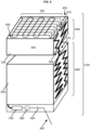
- Figure 6 depicts a refrigeration device wherein a frame 600 can be affixed to an exterior surface of a wall 320 of the liquid-impermeable container 300.
- the liquid-impermeable container includes an interior position 305 that would include phase-change material surrounding a set of evaporator coils when the refrigeration device is in use; for illustration purposes the set of evaporator coils is not shown in Figure 6 .
- the frame is positioned and oriented to hold containers 610 for frozen phase change material adjacent to a section 640 of the exterior surface of a wall 320 of the liquid-impermeable container 300.
- a container for holding frozen phase change material can include a WHO-standard ice pack for medical outreach.
- the frame 600 shown in Figure 6 includes a substantially planar exterior section 650 which is oriented to position the containers 610 for frozen phase change material adjacent to the section 640 of the exterior surface of the wall 320.
- a positioning element 620 including two substantially planar opposing surfaces can be located between the interior face of the substantially planar exterior section 650 of the frame and a substantially planar outer wall of a container 610 for frozen phase change material.
- the frame 600 can include two distinct positioning elements 620.
- Each of the positioning elements can include a tab 625 at one end, the tab 625 of a size and shape to assist a user to reversibly slide the positioning element relative to the frame 600, thereby assisting in the removal of the adjacent container 610.
- the substantially planar exterior section 650 of the frame 600 can include guides 630, the guides of a size and shape to position one or more tabs of each positioning element 620, thereby maintaining the relative orientation of the positioning element 620 to the frame 600.
- Some refrigeration devices can include one or more tension elements within a frame, the tension elements oriented and configured to hold one or more containers for frozen phase change material in direct contact with the exterior surface of the wall of a liquid-impermeable container.
- a frame can include an interior torsional spring.
- a frame can include a semi-elliptical spring positioned and oriented to hold a container.
- Some refrigeration devices can include a frame affixed to an exterior surface of the one or more walls substantially forming the liquid-impermeable container at a position distal to the condenser, the frame of a size and shape to enclose one or more containers for frozen phase change material, wherein the frame is positioned within a second liquid-impermeable container.
- the frame can be positioned and configured to maintain a position of one or more containers for frozen phase change material in thermal contact with the second liquid-impermeable container.
- the second liquid-impermeable container can be configured to contain a material with thermal characteristics sufficient to freeze and maintain the frozen state of one or more containers for frozen phase change material which are in thermal contact with the second liquid-impermeable container.
- the second liquid-impermeable container can be configured to contain a phase change material.
- the second liquid-impermeable container can be configured to contain a second phase change material with a lower freezing temperature than the first phase change material.
- the second liquid-impermeable container can be configured to contain a second phase change material with a higher melting point than the first phase change material.
- the first liquid-impermeable container includes water as a phase change material
- the second liquid-impermeable container can include salt water, which has a freezing temperature below (non-salt) water.
- the second liquid-impermeable container can include a phase change material with a freezing temperature of -10 degrees C.
- the second liquid-impermeable container can include a phase change material with a freezing temperature of -20 degrees C.
- Some refrigeration devices can include: one or more walls substantially forming a liquid-impermeable container, the container configured to hold phase change material internal to a refrigeration device, wherein the one or more walls integrally include a first group of vapor-impermeable structures with a hollow interior connected to form a condenser; at least one active refrigeration unit including a set of evaporator coils, the evaporator coils positioned within an interior of the liquid-impermeable container; one or more walls substantially forming a storage region and integrally including a second group of vapor-impermeable structures with a hollow interior connected to form a evaporator; and a connector affixed to both the condenser and the evaporator, the connector forming a liquid and vapor flow path between the hollow interior of the condenser and the hollow interior of the evaporator, wherein the condenser, the evaporator and the connector form a heat transfer system integral to the refrigeration device.
- the connector can be of a size and shape to permit both liquid and vapor flow between the interior of the evaporator and the interior of the condenser of the heat transfer system.
- Figure 5 depicts a connector 370 positioned between the evaporator 360 and the condenser 350 of a heat transfer system integral to the refrigeration device 100.
- the heat transfer system operates with fluid and vapor flow along a linear, substantially vertical ( i.e. up and down in the view of Figure 5 ) pathway with bilateral movement within each of the hollow interiors of the heat transfer system.
- Figure 7 depicts a refrigeration device 100 according to a non-claimed example.
- a liquid-impermeable container 300 is fabricated with walls 320. Two of the walls 320 of the liquid-impermeable container 300 are in thermal contact with a condenser 350 of a heat transfer system.
- the walls can be fabricated from a roll-bond layered material including the condenser, which is bent and positioned to form the walls of the liquid-impermeable container.
- a set of evaporator coils 330 is positioned within the liquid-impermeable container 300, and a sensor 410 is positioned between an edge of the set of evaporator coils 330 and the interior of a wall 320 of the liquid-impermeable container 300 that is in direct thermal contact with part of the condenser 350.
- the set of evaporator coils 330 are operably attached to a compressor 335, which can be further attached to a controller 380 and a power monitor 390.
- the refrigeration device 100 includes a power connector 395 to a power source, such as an electrical grid system.
- the condenser 350 shown in Figure 7 is fabricated to include multiple internal loops in the liquid and vapor flow pathway within the condenser 350.
- the refrigeration device 100 shown in Figure 7 includes two connectors 370 within the heat transfer system. Each of the connectors 370 provides a bidirectional liquid and vapor flow pathway to evaporative liquid within the hollow interior of the heat transfer system.
- the refrigeration device 100 illustrated in Figure 7 also includes a storage region 310 which is substantially defined by walls 340.
- Two of the walls 340 of the storage region 310 are in thermal contact with an evaporator 360 of the heat transfer system.
- the walls can be fabricated from a roll-bond layered material including the evaporator, which is bent and positioned to form the walls of the storage region.
- the evaporator 360 includes two distinct pathways, one integrated into each side of the evaporator 360. The two distinct pathways are each configured to provide a bidirectional liquid and vapor flow pathway within the hollow interior. The two pathways within the interior of the evaporator 360 are connected at their lowest point 700.
- a refrigeration device can include a heat transfer system including an evaporator, a condenser, and one or more connectors, wherein each connector forms a dual vapor and liquid flow channel between an interior of the evaporator and an interior of the condenser.
- a refrigeration device can include a heat transfer system including an evaporator, a condenser, and one connector.
- a refrigeration device can include a heat transfer system including an evaporator, a condenser, and two connectors.
- the two connectors can be positioned adjacent to two different faces of the refrigeration device.
- the two connectors can be positioned adjacent to a single face of the refrigeration device.
- a refrigeration device can include a heat transfer system including an evaporator, a condenser, and three connectors.
- the three connectors can be positioned adjacent to three different faces of the refrigeration device, such as two side faces and a back face.
- the three connectors can be positioned adjacent to a single face of the refrigeration device.
- the refrigeration device includes a first group of vapor-impermeable structures with a hollow interior connected to form a condenser.
- the vapor-impermeable structures are also liquid- impermeable.
- the vapor-impermeable structures can be fabricated from tubes, tubular structures, regions of roll-bonded material or other materials.
- Some refrigeration devices include a condenser formed from a first group of vapor-impermeable structures wherein the vapor-impermeable structures have multiple sections, and each section is connected at a low position to the connector.
- Some refrigeration devices include a condenser formed from a first group of vapor-impermeable structures wherein the vapor-impermeable structures have multiple sections, and each section is connected at a low position to the connector and at an upper position to at least one other section.
- Some refrigeration devices include a condenser formed from a first group of vapor-impermeable structures wherein the vapor-impermeable structures have multiple sections, and each section is connected at a low position to the connector and at least one intermediate position level.
- the first group of vapor-impermeable structures can form a zig-zag pattern and the structures are connected to each other at intersecting points of the pattern.
- the refrigeration device includes a second group of vapor-impermeable structures with a hollow interior connected to form an evaporator.
- the vapor-impermeable structures are also liquid- impermeable.
- the vapor-impermeable structures can be fabricated from tubes, tubular structures, regions of roll-bonded material or other materials.
- Some refrigeration devices include an evaporator formed from a second group of vapor-impermeable structures wherein the vapor-impermeable structures have multiple sections, and each section is connected at an upper position to the connector.
- Some refrigeration devices include an evaporator formed from a second group of vapor-impermeable structures wherein the vapor-impermeable structures have multiple sections, and each section is connected at an upper position to the connector and at an lower position to at least one other section.
- Some refrigeration devices include an evaporator formed from a second group of vapor-impermeable structures wherein the vapor-impermeable structures have multiple sections, and each section is connected at an upper position to the connector and at least one intermediate position level.
- the second group of vapor-impermeable structures can form a zig-zag pattern and the structures are connected to each other at intersecting points of the pattern.
- the heat transfer system can be fabricated from a contiguous roll-bond material, wherein the roll bond material includes the evaporator, the condenser and the one or more connectors.
- a roll bond material can be fabricated with the desired interior channels forming an evaporator, a condenser and one or more channels between the evaporator and the condenser, wherein the initially substantially flat roll bond material at the time of manufacture is bent to form walls of the storage region and/or the liquid-impermeable container.
- a roll bond material fabricated to include the evaporator, the condenser and the one or more connectors and substantially flat at the time of manufacture can be reconfigured to form the sides of the storage region and/or the liquid-impermeable container after manufacture, and the reconfigured form can be integrated into a refrigeration device during assembly of the refrigeration device.
- the refrigeration device can also include: a thermally-conductive wall integral to the liquid-impermeable container, the thermally-conductive wall including a region projecting beyond an edge of the liquid-impermeable container; an enclosure affixed to the region of the thermally-conductive wall projecting beyond an edge of the liquid-impermeable container of the thermally-conductive wall, the enclosure including an insulating layer adjacent to the region of the thermally-conductive wall; and a frame affixed within the enclosure, the frame of a size and shape to enclose one or more containers for frozen phase change material.
- the thermally-conductive wall integral to the liquid-impermeable container
- the thermally-conductive wall including a region projecting beyond an edge of the liquid-impermeable container
- an enclosure affixed to the region of the thermally-conductive wall projecting beyond an edge of the liquid-impermeable container of the thermally-conductive wall, the enclosure including an insulating layer adjacent to the region of the thermally-conductive wall
- a thermally conductive wall can include a thermally-conductive metal, such as copper or aluminum.
- an insulating layer can include a standard insulation material as used in refrigeration devices, such as foam insulation or one or more vacuum insulated panels.
- a frame of a size and shape to enclose one or more containers for frozen phase change material wherein the frame is affixed within an enclosure can include frame elements such as one or more positioning elements and/or one or more tension elements.
- Figure 8 depicts a refrigeration device in a substantially cross-section view.
- Figure 8 shows portions of a refrigeration device that can be incorporated with other features described herein.
- Figure 8 depicts a liquid-impermeable container 300 including substantially planar walls 320.
- the interior of the liquid-impermeable container 300 includes a region 305 of a size and shape to form a space adjacent to a set of refrigeration coils.
- the exterior vertical walls of the substantially planar walls 320 of the liquid-impermeable container 300 are thermally conductive walls 805.
- an insulating layer 820 Positioned within the enclosure 810 at a position adjacent to the walls of the enclosure 810, there is an insulating layer 820.
- a frame 600 of a size and shape to enclose one or more containers for frozen phase change material is positioned within the insulating layer 820.
- an interior wall 850 divides the insulating layer from a layer of phase change material 840 positioned between the insulating layer 820 and the frame 600.
Landscapes
- Engineering & Computer Science (AREA)
- Chemical & Material Sciences (AREA)
- Combustion & Propulsion (AREA)
- Physics & Mathematics (AREA)
- Mechanical Engineering (AREA)
- Thermal Sciences (AREA)
- General Engineering & Computer Science (AREA)
- Devices That Are Associated With Refrigeration Equipment (AREA)
- Refrigerator Housings (AREA)
Claims (14)
- Kühlvorrichtung (100), umfassend:eine oder mehrere Wände (320), die im Wesentlichen einen flüssigkeitsundurchlässigen Behälter (300) ausbilden, wobei der flüssigkeitsundurchlässige Behälter dazu konfiguriert ist, dass er Phasenübergangsmaterial im Inneren der Kühlvorrichtung enthält;mindestens eine aktive Kühleinheit, einschließlich eines Satzes von Verdampferschlangen (330), wobei die Verdampferschlangen in einem Inneren des flüssigkeitsundurchlässigen Behälters angeordnet sind;eine oder mehrere Wände (340), die im Wesentlichen einen Lagerbereich (310) ausbilden;mindestens einen Temperatursensor (410), angeordnet innerhalb des flüssigkeitsundurchlässigen Behälters zwischen der einen oder den mehreren Wänden und dem Satz von Verdampferschlangen;eine Steuerung (380), wirkverbunden mit der mindestens einen aktiven Kühleinheit und mit dem Temperatursensor;einen Kompressor (335), verbunden mit dem Satz von Verdampferschlangen, wobei die Steuerung zwischen dem Kompressor und einer Kabelverbindung (395) zu einer Stromquelle angeordnet ist, und die Steuerung dazu konfiguriert ist, als Reaktion auf von dem Temperatursensor empfangene Daten Steuersignale an den Kompressor zu senden; undein Wärmeübertragungssystem, einschließlich einer ersten Gruppe von dampfundurchlässigen Strukturen mit einem hohlen Inneren, die verbunden sind, um einen Kondensator (350) auszubilden, der in thermischem Kontakt mit der einen oder den mehreren Wänden steht, die im Wesentlichen einen flüssigkeitsundurchlässigen Behälter ausbilden, einer zweiten Gruppe von dampfundurchlässigen Strukturen mit einem hohlen Inneren, die verbunden sind, um einen Verdampfer (360) auszubilden, in thermischem Kontakt mit der einen oder den mehreren Wänden, die im Wesentlichen den Lagerbereich ausbilden, und eines Verbinders (370) mit einem hohlen Inneren, der sowohl an dem Kondensator als auch an dem Verdampfer befestigt ist, wobei der Verbinder einen Flüssigkeits- und Dampfströmungspfad zwischen dem hohlen Inneren des Kondensators und dem hohlen Inneren des Verdampfers ausbildet.
- Kühlvorrichtung nach Anspruch 1, wobei die eine oder die mehreren Wände, die im Wesentlichen den flüssigkeitsundurchlässigen Behälter ausbilden, mindestens eines einschließen von:einer Vielzahl von Schichten, wobei der Kondensator neben einer Oberfläche von mindestens einer der Vielzahl von Schichten angeordnet ist;eine Vielzahl von Schichten, wobei mindestens eine der einen oder der mehreren Schichten unebene Bereiche einschließt, um mehrere Seiten des flüssigkeitsundurchlässigen Behälters auszubilden.
- Kühlvorrichtung nach Anspruch 1 oder 2, wobei die eine oder die mehreren Wände, die im Wesentlichen den Lagerbereich ausbilden, eine Vielzahl von Schichten einschließen und der Verdampfer neben einer Oberfläche von mindestens einer der Vielzahl von Schichten angeordnet ist.
- Kühlvorrichtung nach einem der vorhergehenden Ansprüche, wobei die mindestens eine aktive Kühleinheit, die den Satz von Verdampferschlangen einschließt, umfasst:einen ersten Abschnitt des Satzes von Verdampferschlangen, angeordnet neben einer Außenoberfläche der einen oder der mehreren Wände, die im Wesentlichen den flüssigkeitsundurchlässigen Behälter ausbilden;einen zweiten Abschnitt des Satzes von Verdampferschlangen, angeordnet im Inneren des flüssigkeitsundurchlässigen Behälters; undeinen Rahmen (600) von einer Größe und Form, um einen oder mehrere Behälter (610) für gefrorenes Phasenübergangsmaterial einzuschließen, wobei der Rahmen in thermischem Kontakt mit dem ersten Abschnitt des Satzes von Verdampferschlangen steht.
- Kühlvorrichtung nach einem der vorhergehenden Ansprüche, wobei die erste Gruppe von dampfundurchlässigen Strukturen mit verbundenem hohlem Inneren, um den Kondensator auszubilden,einstückig ausgebildet ist mit mindestens einer der einen oder der mehreren Wände des flüssigkeitsundurchlässigen Behälters; und/odereine verzweigte Struktur ausbildet.
- Kühlvorrichtung nach einem der vorhergehenden Ansprüche, wobei die zweite Gruppe von dampfundurchlässigen Strukturen mit verbundenem hohlem Inneren, um den Verdampfer auszubilden, einstückig mit mindestens einer der einen oder der mehreren Wände des Lagerbereichs ausgebildet sind.
- Kühlvorrichtung nach einem der vorhergehenden Ansprüche, wobei der Verbinder mehrere Leitungen einschließt, deren erstes Ende an dem Verdampfer befestigt ist und deren zweites Ende an dem Kondensator befestigt ist, und wobei jede Leitung so angeordnet und konfiguriert ist, dass sie einen bidirektionalen Strömungspfad für Flüssigkeit und Dampf zwischen dem Inneren des Verdampfers und dem Inneren des Kondensators bereitstellt.
- Kühlvorrichtung nach einem der vorhergehenden Ansprüche, ferner umfassend mindestens eines von:mindestens einem mit dem Verbinder verbundenen Ventil, wobei das Ventil so angeordnet und konfiguriert ist, dass es die Größe des hohlen Inneren des Verbinders reversibel regelt;eine Leistungsüberwachungseinheit (390), die mit der Steuerung wirkverbunden ist.
- Kühlvorrichtung nach einem der vorhergehenden Ansprüche, ferner umfassend:eine Wärmeregelvorrichtung, wobei die Wärmeregelvorrichtung so angeordnet und konfiguriert ist, dass sie die Größe des hohlen Inneren des Verbinders reversibel regelt;wobei die Steuerung mit der Wärmeregelvorrichtung und dem Temperatursensor wirkverbunden ist.
- Kühlvorrichtung nach Anspruch 9, wobei der Temperatursensor, der innerhalb des flüssigkeitsundurchlässigen Behälters zwischen der einen oder den mehreren Wänden und dem Satz von Verdampferschlangen angeordnet ist, so angeordnet ist, dass er in Phasenübergangsmaterial eingetaucht ist, wenn die Kühlvorrichtung in Betrieb ist.
- Kühlvorrichtung nach einem der vorhergehenden Ansprüche, ferner umfassend:einen Rahmen (600), der an einer Außenoberfläche der einen oder der mehreren Wände befestigt ist, die im Wesentlichen den flüssigkeitsundurchlässigen Behälter ausbilden, an einer Position distal von dem Kondensator, wobei der Rahmen von einer Größe und Form ist, um einen oder mehrere Behälter für gefrorenes Phasenübergangsmaterial einzuschließen; undmindestens einen Spanner innerhalb des Rahmens, wobei der Spanner so ausgerichtet ist, dass er den einen oder die mehreren Behälter gegen die eine oder die mehreren Wände drückt.
- Kühlvorrichtung nach einem der vorhergehenden Ansprüche, ferner umfassend:eine wärmeleitende Wand, die mit dem flüssigkeitsundurchlässigen Behälter einstückig ausgebildet ist, wobei die wärmeleitende Wand einen Bereich einschließt, der über eine Kante des flüssigkeitsundurchlässigen Behälters hinausragt;ein Gehäuse, das an dem Bereich der wärmeleitenden Wand befestigt ist, der über eine Kante des flüssigkeitsundurchlässigen Behälters der wärmeleitenden Wand hinausragt, wobei das Gehäuse eine Isolierschicht einschließt, die an den Bereich der wärmeleitenden Wand angrenzt; undeinen Rahmen (600), der innerhalb des Gehäuses befestigt ist, wobei der Rahmen von einer Größe und Form ist, um einen oder mehrere Behälter für gefrorenes Phasenübergangsmaterial einzuschließen.
- Kühlvorrichtung nach Anspruch 11 oder 12, wobei der Rahmen in einem zweiten flüssigkeitsundurchlässigen Behälter angeordnet ist.
- Kühlvorrichtung nach einem der vorhergehenden Ansprüche, wobei die eine oder die mehreren Wände, die im Wesentlichen den Lagerbereich ausbilden, fünf Seiten einer quaderförmigen Struktur ausbilden.
Applications Claiming Priority (2)
| Application Number | Priority Date | Filing Date | Title |
|---|---|---|---|
| US14/704,107 US9523522B2 (en) | 2013-11-27 | 2015-05-05 | Refrigeration devices including temperature-controlled container systems |
| PCT/US2016/030658 WO2016179215A1 (en) | 2015-05-05 | 2016-05-04 | Refrigeration devices including temperature-controlled container systems |
Publications (4)
| Publication Number | Publication Date |
|---|---|
| EP3292362A1 EP3292362A1 (de) | 2018-03-14 |
| EP3292362A4 EP3292362A4 (de) | 2018-12-05 |
| EP3292362B1 true EP3292362B1 (de) | 2024-07-24 |
| EP3292362C0 EP3292362C0 (de) | 2024-07-24 |
Family
ID=57217840
Family Applications (1)
| Application Number | Title | Priority Date | Filing Date |
|---|---|---|---|
| EP16789968.1A Active EP3292362B1 (de) | 2015-05-05 | 2016-05-04 | Kühlvorrichtungen mit temperaturgesteuerten containersystemen |
Country Status (5)
| Country | Link |
|---|---|
| EP (1) | EP3292362B1 (de) |
| JP (1) | JP6766070B2 (de) |
| CN (1) | CN107709907B (de) |
| WO (1) | WO2016179215A1 (de) |
| ZA (1) | ZA201708197B (de) |
Families Citing this family (4)
| Publication number | Priority date | Publication date | Assignee | Title |
|---|---|---|---|---|
| US10707683B2 (en) * | 2016-09-29 | 2020-07-07 | Tokitae Llc | Directing or modulating electrical power drawn by one or more loads from a solar photovoltaic module array while maintaining a buffer margin |
| EP3634793B1 (de) * | 2017-06-06 | 2024-03-06 | Carrier Corporation | Transportkühlsystem |
| CN109240365B (zh) * | 2018-10-22 | 2024-06-28 | 浩添(厦门)储能股份有限公司 | 一种无源温控箱 |
| CN111735255B (zh) * | 2020-06-29 | 2021-12-14 | 赵军 | 一种除异味冰箱 |
Family Cites Families (15)
| Publication number | Priority date | Publication date | Assignee | Title |
|---|---|---|---|---|
| JPS57210274A (en) * | 1981-06-19 | 1982-12-23 | Sato Kosaburo | Device for accumulating cold |
| EP0098052A3 (de) * | 1982-06-26 | 1984-03-28 | THORN EMI Domestic Appliances Limited | Gefriereinrichtungen |
| JPS6396463A (ja) * | 1986-10-08 | 1988-04-27 | 株式会社東芝 | 冷蔵庫 |
| JPH0718606B2 (ja) * | 1987-01-28 | 1995-03-06 | 株式会社東芝 | 冷凍サイクル |
| JPH071128B2 (ja) | 1987-02-27 | 1995-01-11 | 株式会社東芝 | 冷蔵庫用冷凍サイクル |
| JPH0197159U (de) * | 1987-12-18 | 1989-06-28 | ||
| JP2573082Y2 (ja) * | 1992-03-16 | 1998-05-28 | 株式会社フジクラ | 深夜電力利用型の冷蔵庫 |
| JPH06194025A (ja) | 1992-12-25 | 1994-07-15 | Mitsubishi Electric Corp | 蓄冷式冷蔵庫 |
| JPH08240372A (ja) | 1995-03-07 | 1996-09-17 | Matsushita Refrig Co Ltd | 冷蔵庫 |
| KR19990080066A (ko) * | 1998-04-13 | 1999-11-05 | 한병두 | 냉장고 |
| JP5275929B2 (ja) * | 2008-08-26 | 2013-08-28 | ホシザキ電機株式会社 | 冷却装置 |
| KR20120099638A (ko) * | 2009-09-09 | 2012-09-11 | 스트라우스 워터 리미티드 | 액체에 대한 온도 제어 시스템 |
| US9618254B2 (en) * | 2011-07-21 | 2017-04-11 | Lg Electronics Inc. | Refrigerator |
| KR101286565B1 (ko) * | 2011-12-27 | 2013-07-22 | 국민대학교산학협력단 | 발효식품용 냉장컨테이너 |
| CN104246378B (zh) * | 2012-05-03 | 2018-02-16 | 开利公司 | 具有过冷相变材料的空调系统 |
-
2016
- 2016-05-04 EP EP16789968.1A patent/EP3292362B1/de active Active
- 2016-05-04 CN CN201680038183.3A patent/CN107709907B/zh active Active
- 2016-05-04 WO PCT/US2016/030658 patent/WO2016179215A1/en not_active Ceased
- 2016-05-04 JP JP2017557088A patent/JP6766070B2/ja active Active
-
2017
- 2017-12-01 ZA ZA2017/08197A patent/ZA201708197B/en unknown
Also Published As
| Publication number | Publication date |
|---|---|
| EP3292362A4 (de) | 2018-12-05 |
| EP3292362A1 (de) | 2018-03-14 |
| JP6766070B2 (ja) | 2020-10-07 |
| WO2016179215A1 (en) | 2016-11-10 |
| JP2018514742A (ja) | 2018-06-07 |
| CN107709907A (zh) | 2018-02-16 |
| ZA201708197B (en) | 2019-03-27 |
| HK1250254A1 (zh) | 2018-12-07 |
| CN107709907B (zh) | 2020-10-02 |
| EP3292362C0 (de) | 2024-07-24 |
Similar Documents
| Publication | Publication Date | Title |
|---|---|---|
| US9523522B2 (en) | Refrigeration devices including temperature-controlled container systems | |
| EP3074703B1 (de) | Kühlvorrichtungen mit temperaturgesteuerten containersystemen | |
| EP3074704B1 (de) | Temperaturgesteuerte containersysteme zur verwendung in einer kühlvorrichtung | |
| EP2549210B1 (de) | Kühlschrank | |
| US6308518B1 (en) | Thermal barrier enclosure system | |
| EP3292362B1 (de) | Kühlvorrichtungen mit temperaturgesteuerten containersystemen | |
| US10260819B2 (en) | Thermosiphons for use with temperature-regulated storage devices | |
| CN101842651A (zh) | 具有温度调平装置的用于保鲜产品的冰箱 | |
| EP1421323B1 (de) | Gehäuse mit thermischer wärmedämmung | |
| US12566016B2 (en) | Autonomous portable refrigeration unit | |
| US20180135898A1 (en) | Energy efficient cold storage units | |
| EP3177257B1 (de) | Temperaturgesteuerte medizinische aufbewahrungsvorrichtungen | |
| US9903621B1 (en) | Cooling system with thermal battery | |
| US20180299183A1 (en) | Refrigeration System and Heating Assembly | |
| HK1250254B (zh) | 包括温度受控容器系统的制冷装置 | |
| HK1234817B (zh) | 包括温控容器系统的制冷装置 |
Legal Events
| Date | Code | Title | Description |
|---|---|---|---|
| STAA | Information on the status of an ep patent application or granted ep patent |
Free format text: STATUS: THE INTERNATIONAL PUBLICATION HAS BEEN MADE |
|
| PUAI | Public reference made under article 153(3) epc to a published international application that has entered the european phase |
Free format text: ORIGINAL CODE: 0009012 |
|
| STAA | Information on the status of an ep patent application or granted ep patent |
Free format text: STATUS: REQUEST FOR EXAMINATION WAS MADE |
|
| 17P | Request for examination filed |
Effective date: 20171205 |
|
| AK | Designated contracting states |
Kind code of ref document: A1 Designated state(s): AL AT BE BG CH CY CZ DE DK EE ES FI FR GB GR HR HU IE IS IT LI LT LU LV MC MK MT NL NO PL PT RO RS SE SI SK SM TR |
|
| AX | Request for extension of the european patent |
Extension state: BA ME |
|
| DAV | Request for validation of the european patent (deleted) | ||
| DAX | Request for extension of the european patent (deleted) | ||
| A4 | Supplementary search report drawn up and despatched |
Effective date: 20181106 |
|
| RIC1 | Information provided on ipc code assigned before grant |
Ipc: F25B 23/00 20060101ALN20181029BHEP Ipc: F25D 11/00 20060101ALI20181029BHEP Ipc: F25D 16/00 20060101AFI20181029BHEP |
|
| STAA | Information on the status of an ep patent application or granted ep patent |
Free format text: STATUS: EXAMINATION IS IN PROGRESS |
|
| 17Q | First examination report despatched |
Effective date: 20191016 |
|
| REG | Reference to a national code |
Ref country code: DE Ref legal event code: R079 Free format text: PREVIOUS MAIN CLASS: F25D0023060000 Ipc: F25D0016000000 Ref document number: 602016088556 Country of ref document: DE |
|
| GRAP | Despatch of communication of intention to grant a patent |
Free format text: ORIGINAL CODE: EPIDOSNIGR1 |
|
| STAA | Information on the status of an ep patent application or granted ep patent |
Free format text: STATUS: GRANT OF PATENT IS INTENDED |
|
| RIC1 | Information provided on ipc code assigned before grant |
Ipc: F25B 23/00 20060101ALN20230928BHEP Ipc: F25D 11/00 20060101ALI20230928BHEP Ipc: F25D 16/00 20060101AFI20230928BHEP |
|
| INTG | Intention to grant announced |
Effective date: 20231018 |
|
| GRAJ | Information related to disapproval of communication of intention to grant by the applicant or resumption of examination proceedings by the epo deleted |
Free format text: ORIGINAL CODE: EPIDOSDIGR1 |
|
| STAA | Information on the status of an ep patent application or granted ep patent |
Free format text: STATUS: EXAMINATION IS IN PROGRESS |
|
| GRAP | Despatch of communication of intention to grant a patent |
Free format text: ORIGINAL CODE: EPIDOSNIGR1 |
|
| STAA | Information on the status of an ep patent application or granted ep patent |
Free format text: STATUS: GRANT OF PATENT IS INTENDED |
|
| INTC | Intention to grant announced (deleted) | ||
| RAP3 | Party data changed (applicant data changed or rights of an application transferred) |
Owner name: TOKITAE LLC |
|
| RIN1 | Information on inventor provided before grant (corrected) |
Inventor name: YAGER, DAVID J. Inventor name: WOOD, VICTORIA Y.H. Inventor name: WOOD, LOWELL L., JR. Inventor name: VECCHIONE, MAURIZIO Inventor name: PIECH, DAVID KEITH Inventor name: PETERSON, NELS R. Inventor name: PAL, BRIAN L. Inventor name: MYHRVOLD, NATHAN P. Inventor name: LIU, SHIENG Inventor name: LARUSSON, FRIDRIK Inventor name: ISHIKAWA, MURIEL Y. Inventor name: HU, JENNIFER EZU Inventor name: GATES, WILLIAM Inventor name: FOWLER, LAWRENCE MORGAN Inventor name: ECKHOFF, PHILIP A. Inventor name: CHOU, FONG-LI |
|
| RIC1 | Information provided on ipc code assigned before grant |
Ipc: F25B 23/00 20060101ALN20240214BHEP Ipc: F25D 11/00 20060101ALI20240214BHEP Ipc: F25D 16/00 20060101AFI20240214BHEP |
|
| INTG | Intention to grant announced |
Effective date: 20240228 |
|
| GRAS | Grant fee paid |
Free format text: ORIGINAL CODE: EPIDOSNIGR3 |
|
| GRAA | (expected) grant |
Free format text: ORIGINAL CODE: 0009210 |
|
| STAA | Information on the status of an ep patent application or granted ep patent |
Free format text: STATUS: THE PATENT HAS BEEN GRANTED |
|
| AK | Designated contracting states |
Kind code of ref document: B1 Designated state(s): AL AT BE BG CH CY CZ DE DK EE ES FI FR GB GR HR HU IE IS IT LI LT LU LV MC MK MT NL NO PL PT RO RS SE SI SK SM TR |
|
| REG | Reference to a national code |
Ref country code: GB Ref legal event code: FG4D |
|
| REG | Reference to a national code |
Ref country code: CH Ref legal event code: EP |
|
| REG | Reference to a national code |
Ref country code: IE Ref legal event code: FG4D Ref country code: DE Ref legal event code: R096 Ref document number: 602016088556 Country of ref document: DE |
|
| U01 | Request for unitary effect filed |
Effective date: 20240730 |
|
| U07 | Unitary effect registered |
Designated state(s): AT BE BG DE DK EE FI FR IT LT LU LV MT NL PT SE SI Effective date: 20240813 |
|
| PG25 | Lapsed in a contracting state [announced via postgrant information from national office to epo] |
Ref country code: NO Free format text: LAPSE BECAUSE OF FAILURE TO SUBMIT A TRANSLATION OF THE DESCRIPTION OR TO PAY THE FEE WITHIN THE PRESCRIBED TIME-LIMIT Effective date: 20241024 |
|
| PG25 | Lapsed in a contracting state [announced via postgrant information from national office to epo] |
Ref country code: GR Free format text: LAPSE BECAUSE OF FAILURE TO SUBMIT A TRANSLATION OF THE DESCRIPTION OR TO PAY THE FEE WITHIN THE PRESCRIBED TIME-LIMIT Effective date: 20241025 Ref country code: PL Free format text: LAPSE BECAUSE OF FAILURE TO SUBMIT A TRANSLATION OF THE DESCRIPTION OR TO PAY THE FEE WITHIN THE PRESCRIBED TIME-LIMIT Effective date: 20240724 |
|
| PG25 | Lapsed in a contracting state [announced via postgrant information from national office to epo] |
Ref country code: IS Free format text: LAPSE BECAUSE OF FAILURE TO SUBMIT A TRANSLATION OF THE DESCRIPTION OR TO PAY THE FEE WITHIN THE PRESCRIBED TIME-LIMIT Effective date: 20241124 |
|
| PG25 | Lapsed in a contracting state [announced via postgrant information from national office to epo] |
Ref country code: HR Free format text: LAPSE BECAUSE OF FAILURE TO SUBMIT A TRANSLATION OF THE DESCRIPTION OR TO PAY THE FEE WITHIN THE PRESCRIBED TIME-LIMIT Effective date: 20240724 |
|
| PG25 | Lapsed in a contracting state [announced via postgrant information from national office to epo] |
Ref country code: ES Free format text: LAPSE BECAUSE OF FAILURE TO SUBMIT A TRANSLATION OF THE DESCRIPTION OR TO PAY THE FEE WITHIN THE PRESCRIBED TIME-LIMIT Effective date: 20240724 Ref country code: RS Free format text: LAPSE BECAUSE OF FAILURE TO SUBMIT A TRANSLATION OF THE DESCRIPTION OR TO PAY THE FEE WITHIN THE PRESCRIBED TIME-LIMIT Effective date: 20241024 |
|
| PG25 | Lapsed in a contracting state [announced via postgrant information from national office to epo] |
Ref country code: RS Free format text: LAPSE BECAUSE OF FAILURE TO SUBMIT A TRANSLATION OF THE DESCRIPTION OR TO PAY THE FEE WITHIN THE PRESCRIBED TIME-LIMIT Effective date: 20241024 Ref country code: PL Free format text: LAPSE BECAUSE OF FAILURE TO SUBMIT A TRANSLATION OF THE DESCRIPTION OR TO PAY THE FEE WITHIN THE PRESCRIBED TIME-LIMIT Effective date: 20240724 Ref country code: NO Free format text: LAPSE BECAUSE OF FAILURE TO SUBMIT A TRANSLATION OF THE DESCRIPTION OR TO PAY THE FEE WITHIN THE PRESCRIBED TIME-LIMIT Effective date: 20241024 Ref country code: IS Free format text: LAPSE BECAUSE OF FAILURE TO SUBMIT A TRANSLATION OF THE DESCRIPTION OR TO PAY THE FEE WITHIN THE PRESCRIBED TIME-LIMIT Effective date: 20241124 Ref country code: HR Free format text: LAPSE BECAUSE OF FAILURE TO SUBMIT A TRANSLATION OF THE DESCRIPTION OR TO PAY THE FEE WITHIN THE PRESCRIBED TIME-LIMIT Effective date: 20240724 Ref country code: GR Free format text: LAPSE BECAUSE OF FAILURE TO SUBMIT A TRANSLATION OF THE DESCRIPTION OR TO PAY THE FEE WITHIN THE PRESCRIBED TIME-LIMIT Effective date: 20241025 Ref country code: ES Free format text: LAPSE BECAUSE OF FAILURE TO SUBMIT A TRANSLATION OF THE DESCRIPTION OR TO PAY THE FEE WITHIN THE PRESCRIBED TIME-LIMIT Effective date: 20240724 |
|
| U1N | Appointed representative for the unitary patent procedure changed after the registration of the unitary effect |
Representative=s name: MEISSNER BOLTE DUESSELDORFPATENTANWAELTE RECHTSANWAELTEPARTNERSCHAFT MBB; DE |
|
| PG25 | Lapsed in a contracting state [announced via postgrant information from national office to epo] |
Ref country code: RO Free format text: LAPSE BECAUSE OF FAILURE TO SUBMIT A TRANSLATION OF THE DESCRIPTION OR TO PAY THE FEE WITHIN THE PRESCRIBED TIME-LIMIT Effective date: 20240724 Ref country code: SM Free format text: LAPSE BECAUSE OF FAILURE TO SUBMIT A TRANSLATION OF THE DESCRIPTION OR TO PAY THE FEE WITHIN THE PRESCRIBED TIME-LIMIT Effective date: 20240724 |
|
| PG25 | Lapsed in a contracting state [announced via postgrant information from national office to epo] |
Ref country code: CZ Free format text: LAPSE BECAUSE OF FAILURE TO SUBMIT A TRANSLATION OF THE DESCRIPTION OR TO PAY THE FEE WITHIN THE PRESCRIBED TIME-LIMIT Effective date: 20240724 |
|
| PG25 | Lapsed in a contracting state [announced via postgrant information from national office to epo] |
Ref country code: SK Free format text: LAPSE BECAUSE OF FAILURE TO SUBMIT A TRANSLATION OF THE DESCRIPTION OR TO PAY THE FEE WITHIN THE PRESCRIBED TIME-LIMIT Effective date: 20240724 |
|
| PLBE | No opposition filed within time limit |
Free format text: ORIGINAL CODE: 0009261 |
|
| STAA | Information on the status of an ep patent application or granted ep patent |
Free format text: STATUS: NO OPPOSITION FILED WITHIN TIME LIMIT |
|
| 26N | No opposition filed |
Effective date: 20250425 |
|
| U20 | Renewal fee for the european patent with unitary effect paid |
Year of fee payment: 10 Effective date: 20250528 |
|
| PGFP | Annual fee paid to national office [announced via postgrant information from national office to epo] |
Ref country code: GB Payment date: 20250527 Year of fee payment: 10 |
|
| REG | Reference to a national code |
Ref country code: CH Ref legal event code: H13 Free format text: ST27 STATUS EVENT CODE: U-0-0-H10-H13 (AS PROVIDED BY THE NATIONAL OFFICE) Effective date: 20251223 |
|
| PG25 | Lapsed in a contracting state [announced via postgrant information from national office to epo] |
Ref country code: CH Free format text: LAPSE BECAUSE OF NON-PAYMENT OF DUE FEES Effective date: 20250531 |
|
| PG25 | Lapsed in a contracting state [announced via postgrant information from national office to epo] |
Ref country code: MC Free format text: LAPSE BECAUSE OF FAILURE TO SUBMIT A TRANSLATION OF THE DESCRIPTION OR TO PAY THE FEE WITHIN THE PRESCRIBED TIME-LIMIT Effective date: 20240724 |
|
| PG25 | Lapsed in a contracting state [announced via postgrant information from national office to epo] |
Ref country code: IE Free format text: LAPSE BECAUSE OF NON-PAYMENT OF DUE FEES Effective date: 20250504 |