EP3292363B1 - Préparation de courants d'hydrocarbures à des fins de stockage - Google Patents
Préparation de courants d'hydrocarbures à des fins de stockage Download PDFInfo
- Publication number
- EP3292363B1 EP3292363B1 EP16724489.6A EP16724489A EP3292363B1 EP 3292363 B1 EP3292363 B1 EP 3292363B1 EP 16724489 A EP16724489 A EP 16724489A EP 3292363 B1 EP3292363 B1 EP 3292363B1
- Authority
- EP
- European Patent Office
- Prior art keywords
- liquid
- vessels
- vessel
- product
- vapor
- Prior art date
- Legal status (The legal status is an assumption and is not a legal conclusion. Google has not performed a legal analysis and makes no representation as to the accuracy of the status listed.)
- Active
Links
Images



Classifications
-
- F—MECHANICAL ENGINEERING; LIGHTING; HEATING; WEAPONS; BLASTING
- F25—REFRIGERATION OR COOLING; COMBINED HEATING AND REFRIGERATION SYSTEMS; HEAT PUMP SYSTEMS; MANUFACTURE OR STORAGE OF ICE; LIQUEFACTION SOLIDIFICATION OF GASES
- F25J—LIQUEFACTION, SOLIDIFICATION OR SEPARATION OF GASES OR GASEOUS OR LIQUEFIED GASEOUS MIXTURES BY PRESSURE AND COLD TREATMENT OR BY BRINGING THEM INTO THE SUPERCRITICAL STATE
- F25J3/00—Processes or apparatus for separating the constituents of gaseous or liquefied gaseous mixtures involving the use of liquefaction or solidification
- F25J3/02—Processes or apparatus for separating the constituents of gaseous or liquefied gaseous mixtures involving the use of liquefaction or solidification by rectification, i.e. by continuous interchange of heat and material between a vapour stream and a liquid stream
- F25J3/0204—Processes or apparatus for separating the constituents of gaseous or liquefied gaseous mixtures involving the use of liquefaction or solidification by rectification, i.e. by continuous interchange of heat and material between a vapour stream and a liquid stream characterised by the feed stream
- F25J3/0209—Natural gas or substitute natural gas
- F25J3/0214—Liquefied natural gas
-
- F—MECHANICAL ENGINEERING; LIGHTING; HEATING; WEAPONS; BLASTING
- F25—REFRIGERATION OR COOLING; COMBINED HEATING AND REFRIGERATION SYSTEMS; HEAT PUMP SYSTEMS; MANUFACTURE OR STORAGE OF ICE; LIQUEFACTION SOLIDIFICATION OF GASES
- F25J—LIQUEFACTION, SOLIDIFICATION OR SEPARATION OF GASES OR GASEOUS OR LIQUEFIED GASEOUS MIXTURES BY PRESSURE AND COLD TREATMENT OR BY BRINGING THEM INTO THE SUPERCRITICAL STATE
- F25J3/00—Processes or apparatus for separating the constituents of gaseous or liquefied gaseous mixtures involving the use of liquefaction or solidification
- F25J3/02—Processes or apparatus for separating the constituents of gaseous or liquefied gaseous mixtures involving the use of liquefaction or solidification by rectification, i.e. by continuous interchange of heat and material between a vapour stream and a liquid stream
- F25J3/0204—Processes or apparatus for separating the constituents of gaseous or liquefied gaseous mixtures involving the use of liquefaction or solidification by rectification, i.e. by continuous interchange of heat and material between a vapour stream and a liquid stream characterised by the feed stream
- F25J3/0219—Refinery gas, cracking gas, coke oven gas, gaseous mixtures containing aliphatic unsaturated CnHm or gaseous mixtures of undefined nature
-
- F—MECHANICAL ENGINEERING; LIGHTING; HEATING; WEAPONS; BLASTING
- F25—REFRIGERATION OR COOLING; COMBINED HEATING AND REFRIGERATION SYSTEMS; HEAT PUMP SYSTEMS; MANUFACTURE OR STORAGE OF ICE; LIQUEFACTION SOLIDIFICATION OF GASES
- F25J—LIQUEFACTION, SOLIDIFICATION OR SEPARATION OF GASES OR GASEOUS OR LIQUEFIED GASEOUS MIXTURES BY PRESSURE AND COLD TREATMENT OR BY BRINGING THEM INTO THE SUPERCRITICAL STATE
- F25J3/00—Processes or apparatus for separating the constituents of gaseous or liquefied gaseous mixtures involving the use of liquefaction or solidification
- F25J3/02—Processes or apparatus for separating the constituents of gaseous or liquefied gaseous mixtures involving the use of liquefaction or solidification by rectification, i.e. by continuous interchange of heat and material between a vapour stream and a liquid stream
- F25J3/0228—Processes or apparatus for separating the constituents of gaseous or liquefied gaseous mixtures involving the use of liquefaction or solidification by rectification, i.e. by continuous interchange of heat and material between a vapour stream and a liquid stream characterised by the separated product stream
- F25J3/0233—Processes or apparatus for separating the constituents of gaseous or liquefied gaseous mixtures involving the use of liquefaction or solidification by rectification, i.e. by continuous interchange of heat and material between a vapour stream and a liquid stream characterised by the separated product stream separation of CnHm with 1 carbon atom or more
-
- F—MECHANICAL ENGINEERING; LIGHTING; HEATING; WEAPONS; BLASTING
- F25—REFRIGERATION OR COOLING; COMBINED HEATING AND REFRIGERATION SYSTEMS; HEAT PUMP SYSTEMS; MANUFACTURE OR STORAGE OF ICE; LIQUEFACTION SOLIDIFICATION OF GASES
- F25J—LIQUEFACTION, SOLIDIFICATION OR SEPARATION OF GASES OR GASEOUS OR LIQUEFIED GASEOUS MIXTURES BY PRESSURE AND COLD TREATMENT OR BY BRINGING THEM INTO THE SUPERCRITICAL STATE
- F25J3/00—Processes or apparatus for separating the constituents of gaseous or liquefied gaseous mixtures involving the use of liquefaction or solidification
- F25J3/02—Processes or apparatus for separating the constituents of gaseous or liquefied gaseous mixtures involving the use of liquefaction or solidification by rectification, i.e. by continuous interchange of heat and material between a vapour stream and a liquid stream
- F25J3/0228—Processes or apparatus for separating the constituents of gaseous or liquefied gaseous mixtures involving the use of liquefaction or solidification by rectification, i.e. by continuous interchange of heat and material between a vapour stream and a liquid stream characterised by the separated product stream
- F25J3/0238—Processes or apparatus for separating the constituents of gaseous or liquefied gaseous mixtures involving the use of liquefaction or solidification by rectification, i.e. by continuous interchange of heat and material between a vapour stream and a liquid stream characterised by the separated product stream separation of CnHm with 2 carbon atoms or more
-
- F—MECHANICAL ENGINEERING; LIGHTING; HEATING; WEAPONS; BLASTING
- F25—REFRIGERATION OR COOLING; COMBINED HEATING AND REFRIGERATION SYSTEMS; HEAT PUMP SYSTEMS; MANUFACTURE OR STORAGE OF ICE; LIQUEFACTION SOLIDIFICATION OF GASES
- F25J—LIQUEFACTION, SOLIDIFICATION OR SEPARATION OF GASES OR GASEOUS OR LIQUEFIED GASEOUS MIXTURES BY PRESSURE AND COLD TREATMENT OR BY BRINGING THEM INTO THE SUPERCRITICAL STATE
- F25J3/00—Processes or apparatus for separating the constituents of gaseous or liquefied gaseous mixtures involving the use of liquefaction or solidification
- F25J3/08—Separating gaseous impurities from gases or gaseous mixtures or from liquefied gases or liquefied gaseous mixtures
-
- F—MECHANICAL ENGINEERING; LIGHTING; HEATING; WEAPONS; BLASTING
- F25—REFRIGERATION OR COOLING; COMBINED HEATING AND REFRIGERATION SYSTEMS; HEAT PUMP SYSTEMS; MANUFACTURE OR STORAGE OF ICE; LIQUEFACTION SOLIDIFICATION OF GASES
- F25J—LIQUEFACTION, SOLIDIFICATION OR SEPARATION OF GASES OR GASEOUS OR LIQUEFIED GASEOUS MIXTURES BY PRESSURE AND COLD TREATMENT OR BY BRINGING THEM INTO THE SUPERCRITICAL STATE
- F25J2200/00—Processes or apparatus using separation by rectification
- F25J2200/74—Refluxing the column with at least a part of the partially condensed overhead gas
-
- F—MECHANICAL ENGINEERING; LIGHTING; HEATING; WEAPONS; BLASTING
- F25—REFRIGERATION OR COOLING; COMBINED HEATING AND REFRIGERATION SYSTEMS; HEAT PUMP SYSTEMS; MANUFACTURE OR STORAGE OF ICE; LIQUEFACTION SOLIDIFICATION OF GASES
- F25J—LIQUEFACTION, SOLIDIFICATION OR SEPARATION OF GASES OR GASEOUS OR LIQUEFIED GASEOUS MIXTURES BY PRESSURE AND COLD TREATMENT OR BY BRINGING THEM INTO THE SUPERCRITICAL STATE
- F25J2205/00—Processes or apparatus using other separation and/or other processing means
- F25J2205/02—Processes or apparatus using other separation and/or other processing means using simple phase separation in a vessel or drum
- F25J2205/04—Processes or apparatus using other separation and/or other processing means using simple phase separation in a vessel or drum in the feed line, i.e. upstream of the fractionation step
-
- F—MECHANICAL ENGINEERING; LIGHTING; HEATING; WEAPONS; BLASTING
- F25—REFRIGERATION OR COOLING; COMBINED HEATING AND REFRIGERATION SYSTEMS; HEAT PUMP SYSTEMS; MANUFACTURE OR STORAGE OF ICE; LIQUEFACTION SOLIDIFICATION OF GASES
- F25J—LIQUEFACTION, SOLIDIFICATION OR SEPARATION OF GASES OR GASEOUS OR LIQUEFIED GASEOUS MIXTURES BY PRESSURE AND COLD TREATMENT OR BY BRINGING THEM INTO THE SUPERCRITICAL STATE
- F25J2215/00—Processes characterised by the type or other details of the product stream
- F25J2215/04—Recovery of liquid products
-
- F—MECHANICAL ENGINEERING; LIGHTING; HEATING; WEAPONS; BLASTING
- F25—REFRIGERATION OR COOLING; COMBINED HEATING AND REFRIGERATION SYSTEMS; HEAT PUMP SYSTEMS; MANUFACTURE OR STORAGE OF ICE; LIQUEFACTION SOLIDIFICATION OF GASES
- F25J—LIQUEFACTION, SOLIDIFICATION OR SEPARATION OF GASES OR GASEOUS OR LIQUEFIED GASEOUS MIXTURES BY PRESSURE AND COLD TREATMENT OR BY BRINGING THEM INTO THE SUPERCRITICAL STATE
- F25J2215/00—Processes characterised by the type or other details of the product stream
- F25J2215/62—Ethane or ethylene
-
- F—MECHANICAL ENGINEERING; LIGHTING; HEATING; WEAPONS; BLASTING
- F25—REFRIGERATION OR COOLING; COMBINED HEATING AND REFRIGERATION SYSTEMS; HEAT PUMP SYSTEMS; MANUFACTURE OR STORAGE OF ICE; LIQUEFACTION SOLIDIFICATION OF GASES
- F25J—LIQUEFACTION, SOLIDIFICATION OR SEPARATION OF GASES OR GASEOUS OR LIQUEFIED GASEOUS MIXTURES BY PRESSURE AND COLD TREATMENT OR BY BRINGING THEM INTO THE SUPERCRITICAL STATE
- F25J2230/00—Processes or apparatus involving steps for increasing the pressure of gaseous process streams
- F25J2230/60—Processes or apparatus involving steps for increasing the pressure of gaseous process streams the fluid being hydrocarbons or a mixture of hydrocarbons
-
- F—MECHANICAL ENGINEERING; LIGHTING; HEATING; WEAPONS; BLASTING
- F25—REFRIGERATION OR COOLING; COMBINED HEATING AND REFRIGERATION SYSTEMS; HEAT PUMP SYSTEMS; MANUFACTURE OR STORAGE OF ICE; LIQUEFACTION SOLIDIFICATION OF GASES
- F25J—LIQUEFACTION, SOLIDIFICATION OR SEPARATION OF GASES OR GASEOUS OR LIQUEFIED GASEOUS MIXTURES BY PRESSURE AND COLD TREATMENT OR BY BRINGING THEM INTO THE SUPERCRITICAL STATE
- F25J2240/00—Processes or apparatus involving steps for expanding of process streams
- F25J2240/40—Expansion without extracting work, i.e. isenthalpic throttling, e.g. JT valve, regulating valve or venturi, or isentropic nozzle, e.g. Laval
-
- F—MECHANICAL ENGINEERING; LIGHTING; HEATING; WEAPONS; BLASTING
- F25—REFRIGERATION OR COOLING; COMBINED HEATING AND REFRIGERATION SYSTEMS; HEAT PUMP SYSTEMS; MANUFACTURE OR STORAGE OF ICE; LIQUEFACTION SOLIDIFICATION OF GASES
- F25J—LIQUEFACTION, SOLIDIFICATION OR SEPARATION OF GASES OR GASEOUS OR LIQUEFIED GASEOUS MIXTURES BY PRESSURE AND COLD TREATMENT OR BY BRINGING THEM INTO THE SUPERCRITICAL STATE
- F25J2245/00—Processes or apparatus involving steps for recycling of process streams
- F25J2245/02—Recycle of a stream in general, e.g. a by-pass stream
-
- F—MECHANICAL ENGINEERING; LIGHTING; HEATING; WEAPONS; BLASTING
- F25—REFRIGERATION OR COOLING; COMBINED HEATING AND REFRIGERATION SYSTEMS; HEAT PUMP SYSTEMS; MANUFACTURE OR STORAGE OF ICE; LIQUEFACTION SOLIDIFICATION OF GASES
- F25J—LIQUEFACTION, SOLIDIFICATION OR SEPARATION OF GASES OR GASEOUS OR LIQUEFIED GASEOUS MIXTURES BY PRESSURE AND COLD TREATMENT OR BY BRINGING THEM INTO THE SUPERCRITICAL STATE
- F25J2245/00—Processes or apparatus involving steps for recycling of process streams
- F25J2245/90—Processes or apparatus involving steps for recycling of process streams the recycled stream being boil-off gas from storage
-
- F—MECHANICAL ENGINEERING; LIGHTING; HEATING; WEAPONS; BLASTING
- F25—REFRIGERATION OR COOLING; COMBINED HEATING AND REFRIGERATION SYSTEMS; HEAT PUMP SYSTEMS; MANUFACTURE OR STORAGE OF ICE; LIQUEFACTION SOLIDIFICATION OF GASES
- F25J—LIQUEFACTION, SOLIDIFICATION OR SEPARATION OF GASES OR GASEOUS OR LIQUEFIED GASEOUS MIXTURES BY PRESSURE AND COLD TREATMENT OR BY BRINGING THEM INTO THE SUPERCRITICAL STATE
- F25J2270/00—Refrigeration techniques used
- F25J2270/12—External refrigeration with liquid vaporising loop
-
- F—MECHANICAL ENGINEERING; LIGHTING; HEATING; WEAPONS; BLASTING
- F25—REFRIGERATION OR COOLING; COMBINED HEATING AND REFRIGERATION SYSTEMS; HEAT PUMP SYSTEMS; MANUFACTURE OR STORAGE OF ICE; LIQUEFACTION SOLIDIFICATION OF GASES
- F25J—LIQUEFACTION, SOLIDIFICATION OR SEPARATION OF GASES OR GASEOUS OR LIQUEFIED GASEOUS MIXTURES BY PRESSURE AND COLD TREATMENT OR BY BRINGING THEM INTO THE SUPERCRITICAL STATE
- F25J2270/00—Refrigeration techniques used
- F25J2270/60—Closed external refrigeration cycle with single component refrigerant [SCR], e.g. C1-, C2- or C3-hydrocarbons
Definitions
- Liquefying hydrocarbon gas can facilitate transport and storage of hydrocarbons and related material. Generally, the processes greatly reduce the volume of gas. The resulting liquid is well-suited to transit long distance through pipelines and related infrastructure.
- US 6526777 B1 relates to a process for liquefying natural gas in conjunction with processing natural gas to recover natural gas liquids (NGL).
- NGL natural gas liquids
- the natural gas stream to be liquefied is taken from one of the streams in the NGL recovery plant and cooled under pressure to condense it.
- a distillation stream is withdrawn from the NGL recovery plant to provide some of the cooling required to condense the natural gas stream.
- the condensed natural gas stream is expanded to an intermediate pressure and supplied to a mid-column feed point on a distillation column.
- the bottom product from this distillation column preferentially contains the majority of any hydrocarbons heavier than methane that would otherwise reduce the purity of the liquefied natural gas, and is routed to the NGL recovery plant so that these heavier hydrocarbons can be recovered in the NGL product.
- the overhead vapor from the distillation column is cooled and condensed, and a portion of the condensed stream is supplied to a top feed point on the distillation column to serve as reflux. A second portion of the condensed stream is expanded to low pressure to form the liquefied natural gas stream.
- US 2008072620 A1 discloses a process for treating a crude containing natural gas comprising supplying the crude to a stabilization unit to obtain a gaseous stream and crude oil; supplying a compressed, gaseous stream at a low temperature to the bottom of a first column; partly condensing the first gaseous overhead stream, returning the liquid phase to the first column and supplying the methane-rich stream to a liquefaction plant; supplying an expanded bottom stream at a low temperature to the top of a second column; removing from the top of the second column a second gaseous overhead stream, and removing from the bottom of the second column a liquid bottom stream; vaporizing part of the bottom stream and introducing the vapour into the bottom of the second column; and introducing the remainder of the bottom stream into a crude oil stream at an appropriate point in or upstream of the stabilization unit.
- US 4061481 A deals with the processing of gas streams containing hydrocarbons and other gases of similar volatility to recover high yields of components such as ethane, propane, and heavier hydrocarbons therefrom by expanding said gas stream in at least two stages through turboexpanders, each stage cooling the gas stream and producing energy in the form of horsepower used to drive a recompressor unit or other mechanical apparatus.
- Condensed liquids are collected intermediate the expansion stages.
- a supplemental gas cooling stage and condensed liquid recovery occurs following each expansion stage.
- the bottoms streams from the primary distillation zone and the demethanizer are fractionated into respective streams consisting essentially of ethylene 356 , ethane 358 , propylene 364 , propane 366 , C4's 346 , and C5+ 348.
- US 3729944 A discloses a gas-liquid mixture is introduced into a phase separation zone wherein there is effected a separation between a gas phase and its equilibrium liquid; the gas phase is required to perform a maximum of expansion work and then passed in indirect heat exchange with the gas-liquid mixture; the desired cooling of the gas-liquid mixture not completely supplied by the gas phase is supplied by a portion of the equilibrium liquid with the remaining portion of the equilibrium liquid being passed to convenient locations for further processing.
- US 4171964 A discloses a processing of gas streams containing hydrocarbons and other gases of similar volatility to recover high yields of components such as ethane, propane, and heavier hydrocarbons therefrom by cooling said gas stream under pressure to form a liquid portion, and expanding the liquid portion to a pressure lower than feed pressure whereby a part of the liquid portion vaporizes to cool the remaining part of the liquid portion is improved by pre-cooling the liquid portion prior to flash expansion.
- this is accomplished by dividing the remaining part of the liquid portion into a first and second stream, directing the first liquid stream into heat exchange relation with the liquid portion of the feed stream prior to expansion to warm the first liquid stream and pre-cool the liquid portion prior to expansion. Both first and second liquid streams are then supplied to a fractionating column, the second stream being supplied to the fractionating column at a point thereon higher than the first stream.
- hydrocarbon liquid For pipeline transportation, it may be most economical to transport hydrocarbon liquid at ambient temperature and high pressure because it is easier to address requirements for wall thickness of the pipe without the need to insulate the entire length of the pipeline. For storage, it may be better for hydrocarbon liquid to be at or near atmospheric pressure to economically resolve the insulation and wall thickness requirements.
- the invention relates generally to hydrocarbon processing, wherein a fluid circuit that incorporates components to prepare an incoming liquid ethane stream for storage. These components include a distilling unit embodied as a plurality of vessels to separate the incoming liquid ethane stream into a liquid for storage.
- the fluid circuit also includes a demethanizer column that is in position downstream of the vessels.
- the invention configure the vessels to permit a position for the demethanizer column in the back or "tail" end of the fluid circuit.
- the vessels can reduce the amount of flash gas processed by the demethanizer column.
- compression requirements are lower in order maintain pressure of the flash gas and boil-off gas that the embodiments combine together for processing at the demethanizer column.
- This boil-off gas can originate from storage of the final, liquid ethane product.
- horsepower requirements for the embodiments will compare favorably to other processes that may utilize, for example, one or more demethanizer columns at the "front" end of the fluid circuit.
- the embodiments can also be configured to recover other hydrocarbons from the incoming ethane stream. These other hydrocarbons are particularly useful as fuel gas and/or as raw materials for use in various petrochemical applications. In this way, the embodiments may avoid unnecessary loss of products from the feed stream, effectively adding value and/or optimizing profitability of the liquefaction process.
- the embodiments may find use in many different types of processing facilities. These facilities may be found onshore and/or offshore. In one application, the embodiments can incorporate into and/or as part of processing facilities that reside on land, typically on (or near) shore. These processing facilities can process the feedstock from production facilitates found both onshore and offshore. Offshore production facilitates use pipelines to transport feedstock extracted from gas fields and/or gas-laden oil-rich fields, often from deep sea wells, to the processing facilitates. For liquefying processes, the processing facility can turn the feedstock to liquid using suitably configured refrigeration equipment or "trains.” In other applications, the embodiments can incorporate into production facilities on board a ship (or like floating vessel).
- the discussion below contemplates embodiments that are useful to process liquid hydrocarbons for storage.
- the embodiments herein feature improvements that can reduce the overall size and, in turn, the overall investment necessary for commercial processing of ethane.
- Large operations that process quantities of liquid ethane in excess of 19078 m3 (120,000 barrels) per day may benefit in particular because the embodiments can use components that are substantially smaller than similar components, even when such similar components are "split" to more easily fabricate and ship to the installation site or facility.
- Other embodiments are contemplated with the scope of the disclosed subject matter.
- FIG. 1 illustrates a schematic diagram of an exemplary embodiment of a processing system 100 (also "system 100") for use to process hydrocarbon streams.
- the system 100 can receive a feedstock 102 from a source 104.
- the feedstock 102 can comprise liquid with a composition that is predominantly ethane, although the system 100 may be useful for other compositions as well.
- incoming feedstock 102 may comprise ethane liquid with a first concentration of methane of approximately 3 % or less.
- the system 100 can have a fluid circuit 106 to process incoming feedstock 102 to form one or more products (e.g., a first product 108 and a second product 110).
- the products 108, 110 can exit the system 100 to a storage facility 112, a pipeline 114, and/or other collateral process equipment.
- the fluid circuit 106 is configured so that the first product 108 meet specifications for storage, e.g., at the storage facility 112. These specifications may require a second concentration of methane that is lower than the first concentration of incoming feedstock 102. In one example, the second concentration of methane in the first product 108 for may be approximately 1 % or less.
- the fluid circuit 106 can circulate fluids (e.g., gases and liquids). For clarity, these fluids are identified and discussed in connection with operations of the embodiments herein as a process stream 116.
- the embodiments may include a pre-cooling unit 118, a distilling unit 120, a mixing unit 122, and a demethanizer unit 124.
- the fluid circuit 106 can receive a return stream 126 that may originate from the storage facility 112, although this disclosure is not limited only to that configuration.
- the fluid circuit 106 can also be configured to separately couple the separator unit 120 and the demethanizer unit 124, as shown by the phantom line enumerated by the numeral 128.
- the fluid circuit 106 may couple with certain collateral equipment, namely, a refrigeration unit 130 that couples with the fluid circuit 106.
- a refrigeration unit 130 may circulate a refrigerant 132 to coolers and/or like devices that condition temperature of the process stream 116 at one or more of the units 118, 120, 122, 124.
- the demethanizer unit 124 permits the demethanizer unit 124 to be located at the end of the fluid circuit 106. This position reduces the volume of incoming feedstock 102 that the demethanizer unit 124 processes during operation of the system 100. Some embodiments only require the demethanizer unit 124 to process approximately 20 % of incoming feedstock 102, with the distilling unit 120 (and or other units in the fluid circuit 106) configured to process approximately 80 % of incoming feedstock 102. In such embodiments, the demethanizer unit 124 receives and processes predominantly "flashed" gas (also, "vapor") that results from one or more of the other units 118, 120, 122.
- "flashed" gas also, "vapor
- the demethanizer unit 124 has a diameter that is 2,72 m (nine (9) feet) or less.
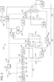
- FIG. 2 illustrates an example of components to implement the processing system 100 to achieve the second concentration of methane in the first product 108.
- the refrigeration unit 130 can be configured to disperse the refrigerant 132 as a first refrigerant 134 and a second refrigerant 136.
- the refrigerants 134, 136 can facilitate thermal transfer at coolers disposed throughout the fluid circuit 106.
- the coolers can be configured to implement cooling in stages (also, "cooling stages") to reduce temperature of the process stream 116.
- Compositions for the refrigerants 134, 136 can include propylene and ethylene, respectively; however, other compositions may also pose as workable solutions to affect thermal transfer in the coolers.
- the first refrigerant 134 can circulate across one or more coolers (e.g., a first cooler 138, a second cooler 140, and a third cooler 142).
- the second refrigerant 136 can regulate temperature at coolers at each of the separation unit 120 and the demethanizer unit 124.
- the units 120, 124 can be configured to include one or more coolers (e.g., a fourth cooler 144, a fifth cooler 146, and a sixth cooler 148, a seventh cooler 150).
- the fluid circuit 106 may include a separator 152 to form vapor, liquid, and mixed phase products.
- the separator 152 can generally be configured as a plurality of vessels (e.g., a first vessel 154, a second vessel 156, and a third vessel 158).
- the fluid circuit 106 may also include a fourth vessel 160 that couples with a demethanizer column 162 at the demethanizer unit 124.
- the components 160, 162 may benefit from use of one or more peripheral components (e.g., a first peripheral component 164 and a second peripheral component 166).
- peripheral components 164, 166 can include pumps, boilers, heaters, and like devices that can facilitate operation of the vessel 160 and/or the demethanizer 162.
- the second peripheral component 166 may embody a boiler that couples with both the fourth vessel 160 and with the refrigeration unit 130 to condition temperature of the first refrigerant 134.
- the fluid circuit 106 may couple the vessels 156, 158 with a flash drum 168 or like vessel.
- the flash drum 168 can couple with the storage facility 112 to provide the first product 108 for storage.
- the fluid circuit 106 may also include one or more throttling devices (e.g., a first throttling device 170, a second throttling device 172, and a third throttling device 174).
- throttling 170, 172, 174 can include valves (e.g., Joule-Thompson valves) and/or devices that are similarly situated to throttle the flow of a fluid stream.
- These devices may be interposed between components in the fluid circuit 106 as necessary to achieve certain changes in fluid parameters (e.g., temperature, pressure, etc.). As noted below, the device may provide an expansion stage and a cooling stage, where applicable, to reduce pressure and/or temperature of the process stream 116.
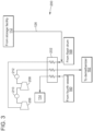
- FIG. 3 illustrates an example of a mixing unit 200 for use in the processing system 100 of FIGS. 1 and 2 .
- This example can couple with the storage facility 112, the separation unit 120, and the demethanizer unit 162.
- the mixing unit 200 may include a heat exchanger 202 that couples with a compression system 204.
- the heat exchanger 202 can include crossflow devices of varying designs (e.g., spiral flow, counter-current flow, distributed flow, etc.), although other devices and designs that can effectively transfer thermal energy may also be desirable.
- the compression system can have one or more compressors (e.g., a first compressor 206 and a second compressor 208) and one or more coolers (e.g., a first cooler 210 and a second cooler 212).
- the fluid circuit 106 can direct the process stream 116 through the various components to generate the products 108, 110.
- the pre-cooling unit 118 can sub-cool the incoming feedstock 102 from a first temperature to a second temperature that is less than the first temperature.
- Incoming feedstock 102 may enter the device (at 176) at ambient temperature that prevails at the system 100 and/or surrounding facility.
- the coolers 138, 140, 142 can effectively reduce temperature of incoming feedstock 102 by at least about 48,8 °C (120 °F), with one example being configured to condition the process stream 116 to exit the cooling stages (at 178) at approximately -40 °C (°F).
- the fourth cooler 144 may provide a cooling stage to further reduce temperature of the liquefied ethane stream.
- This cooling stage can reduce temperature of the liquefied ethane stream by at least approximately -12,2 °C (10 °F), with one example of the fourth cooler 144 being configured so that the liquefied ethane stream exits this cooling stage (at 180) at approximately -45,5 °C (-50 °F).
- the fluid circuit 106 can direct the liquefied ethane stream to the first throttling device 170.
- this device can be configured to reduce pressure of the liquefied ethane stream 116 from a first pressure to a second pressure that is less than the first pressure.
- the first pressure may correspond with the super critical pressure for incoming feedstock 102. For liquid ethane, this super critical pressure may be approximately 5515805,8 Pa (800 psig) or greater.
- the expansion stage can reduce pressure by at least approximately 4826330 Pa (700 psig). In one example, the first expansion unit 170 being configured so that the liquefied ethane stream exits this expansion stage (at 182) at approximately 689475,7 Pa (100 psig). Expansion across the first throttling unit 170 may also provide a cooling stage to further lower the temperature of the process stream 108, e.g., to approximately -50 °C (-58 °F).
- the fluid circuit 106 can process the liquefied ethane stream at the reduced pressure and reduced temperature to obtain the first product 108.
- the first product 108 will meet the methane concentration and other specifications for storage. Examples of these processes can form a top product and a bottom product at each of the vessels 154, 156, 158.
- the top product can be in vapor form.
- the bottom product can be in liquid form and/or mixed-phase form (e.g., a combination of liquid and vapor), often depending on temperature and/or pressure of the resulting fluid.
- the fluid circuit 106 can be configured to direct a mixed-phase bottom product from the first vessel 154 to the second vessel 156.
- the second throttling unit 172 can provide an expansion stage (and a cooling stage) to reduce pressure and temperature and produce a mixed-phase product between the vessels 154, 156.
- the mixed-phase product can exit the expansion/cooling stage (at 184) at approximately 55158 Pa (8 psig) and approximately -84.4 °C (-120 °F) prior to entry into the second vessel 156.
- the fluid circuit 106 can be configured to combine the vapor top products from the vessels 154, 156 upstream of the fifth cooler 146.
- the fifth cooler 146 can provide a cooling stage so that the combined mixed phase product exits the cooling stage (at 186) at approximately -94.4 °C (-138 °F) prior to entry into the third vessel 156.
- the fluid circuit 106 can also combine the bottom product from the vessels 156, 158, either in liquid form and/or mixed-phase form, as the process stream 116.
- the sixth cooler 148 can provide a cooling stage so that the combined mixed phase bottom product exits the cooling stage (at 188) at approximately -91.1 °C (-132 °F) and approximately 13789.5 Pa (2 psig).
- the fluid circuit 106 can direct the combined liquid bottom product to the flash drum 168 at a reduced temperature and pressure.
- the flash drum 168 can form a liquid product and a vapor product.
- the fluid circuit 106 can direct the liquid product to the storage facility 112 or elsewhere as desired.
- the fluid circuit 106 can direct the vapor product from the flash drum 168 through the heat exchanger 202. Downstream of the heat exchanger 202, the fluid circuit 106 can combine the vapor product from the flash drum 168 with incoming return stream 126, often the boil-off vapor that forms at the storage facility 112.
- the compressors 206, 208 and the coolers 210, 212 can condition temperature and pressure of the combined vapor stream upstream of the heat exchanger 202.
- the conditioned vapor flows onto the demethanizer column 162 via the heat exchanger 202.
- processes at the demethanizer column 162 can form a top product and a bottom product, typically in vapor phase and liquid (or mixed) phase, respectively.
- the bottom product exits the demethanizer column 162 to the third throttling device 174.
- the third throttling device 174 can provide an expansion stage to reduce pressure (and temperature) of this bottom product between the second vessel 156 and the demethanizer column 162.
- the bottom product can enter the expansion stage (at 194) at approximately 3240535,9 Pa (470 psig) and approximately 13.8 °C (57 °F) and exit the expansion stage (at 192) at approximately 55158 Pa (8 psig) and approximately -81.1 °C (-114 °F) prior to entry into the second vessel 156.
- the fluid circuit 106 can be configured to recycle the top product from the demethanizer column 162.
- the seventh cooler 150 may operate as an overhead condenser for the demethanizer column 162. This overhead condenser can provide a cooling stage so that the top product exits the cooling stage (at 196).
- the cooled top product enters the fourth vessel 160, operating here as a reflux drum.
- the fourth vessel 160 can form a top product and a bottom product.
- the pump 164 can pump the liquid bottom product from the fourth vessel 160 back to the demethanizer column 162.
- the top product can be predominantly methane vapor that exits the system 100 as the second product 110 via the heat exchanger 202 ( FIG. 3 ).
- FIGS. 4 , 5 , and 6 depict flow diagrams of a process 300 to prepare incoming liquid ethane (and, generally, feedstock 102) for storage.
- the process 300 can include, at stage 302, distilling an incoming feedstock at a plurality of vessels to form a vapor and a liquid for storage.
- the process 300 can also include, at stage 304, directing the vapor to a demethanizer column and, at stage 306, circulating liquid from the demethanizer back to the plurality of vessels.
- the process 300 can also include, at stage 308, cooling the incoming feedstock upstream of the plurality of vessels and, at stage 310, throttling flow of the incoming feedstock upstream of the plurality of vessels.
- stage 302 in the process 300 can incorporate various stages to distill the incoming feedstock, as desired.
- these stages may include, at stage 312, forming a first top product and a first bottom product from the incoming feedstock in a first vessel.
- the stages may also include, at stage 314, directing the first bottom product and the liquid from the demethanizer column to a second vessel and, at stage 316, separating the first bottom product into a second top product and a second bottom product in the second vessel.
- the stages may further include, at stage 318, mixing the first top product with the second top product upstream of a third vessel, at stage 320, cooling the first top product and the second top product upstream of the third vessel, and, at stage 322, forming a third bottom product from the first top product and the second top product in the third vessel.
Landscapes
- Engineering & Computer Science (AREA)
- Physics & Mathematics (AREA)
- Mechanical Engineering (AREA)
- Thermal Sciences (AREA)
- General Engineering & Computer Science (AREA)
- Chemical & Material Sciences (AREA)
- Chemical Kinetics & Catalysis (AREA)
- General Chemical & Material Sciences (AREA)
- Oil, Petroleum & Natural Gas (AREA)
- Separation By Low-Temperature Treatments (AREA)
- Organic Low-Molecular-Weight Compounds And Preparation Thereof (AREA)
- Filling Or Discharging Of Gas Storage Vessels (AREA)
Claims (10)
- Procédé de liquéfaction d'une charge d'alimentation entrante (102) comprenant principalement un liquide d'éthane en liquide qui répond à des spécifications de l'éthane liquide, comprenant :la distillation d'une charge d'alimentation entrante (102) au niveau d'une pluralité de cuves (154, 156, 158, 168) afin de former une vapeur et de l'éthane liquide pour le stockage ;l'acheminement de la vapeur vers une colonne de déméthanisation (162) ; etla circulation d'un liquide à partir de la colonne de déméthanisation (162) en retour vers la pluralité de cuves (154, 156, 158, 168),au niveau de la pluralité de cuves (154, 156, 158, 168) :la formation d'un premier produit de tête et d'un premier produit de fond à partir de la charge d'alimentation entrante (102) ;la séparation du premier produit de fond en second produit de tête et en deuxième produit de fond ; etla formation d'un troisième produit de fond à partir du premier produit de tête et du second produit de tête,dans lequel le deuxième produit de fond et le troisième produit de fond répondent à des spécifications de l'éthane liquide ;dans lequel la pluralité de cuves (154, 156, 158, 168) comprennent un ballon de détente (168), le procédé comprenant en outre l'acheminement du deuxième produit de fond et du troisième produit de fond vers le ballon de détente (168), dans lequel la vapeur et l'éthane liquide proviennent du ballon de détente (168), etil comprend en outre le mélange de la vapeur avec un flux de retour (126) en amont de la colonne de déméthanisation (162), le flux de retour (126) comprenant des gaz d'évaporation.
- Procédé de liquéfaction selon la revendication 1, comprenant en outre :
le refroidissement de la charge d'alimentation entrante (102) en amont de la pluralité de cuves (154, 156, 158, 168). - Procédé de liquéfaction selon la revendication 1, comprenant en outre :
l'étranglement d'un écoulement de la charge d'alimentation entrante (102) en amont de la pluralité de cuves (154, 156, 158, 168). - Procédé de liquéfaction selon la revendication 1, comprenant en outre :
l'acheminement du premier produit de fond et du liquide à partir de la colonne de déméthanisation (162) vers l'une de la pluralité de cuves (154, 156, 158, 168). - Procédé de liquéfaction selon la revendication 1, comprenant en outre :
le refroidissement du deuxième produit de fond et du troisième produit de fond en amont du ballon de détente (168) et en aval de la pluralité de cuves (154, 156, 158, 168). - Procédé de liquéfaction selon la revendication 1, comprenant en outre :
le mélange du premier produit de tête avec le second produit de tête en amont de l'une de la pluralité de cuves (154, 156, 158, 168). - Procédé de liquéfaction selon la revendication 1, comprenant en outre :
le refroidissement du premier produit de tête et du second produit de tête en amont de l'une de la pluralité de cuves (154, 156, 158, 168). - Système de traitement de gaz (100), comprenant :
un circuit de fluide (106) conçu pour traiter une charge d'alimentation entrante (102) comprenant principalement un liquide d'éthane en liquide qui répond à des spécifications de l'éthane liquide, le circuit de fluide (106) comprenant :une unité de distillation (120) comprenant une pluralité de cuves (154, 156, 158, 168), la pluralité de cuves (154, 156, 158, 168) étant conçues pour former une charge d'alimentation entrante (102) en une vapeur et un liquide qui répond à des spécifications de l'éthane liquide ; etune colonne de déméthanisation (162) accouplée à la pluralité de cuves (154, 156, 158, 168), la colonne de déméthanisation (162) étant conçue pour former un liquide à partir de la vapeur,dans lequel le circuit de fluide (106) est conçu pour acheminer le liquide à partir de la colonne de déméthanisation (162) vers l'une de la pluralité de cuves (154, 156, 158),dans lequel la pluralité de cuves (154, 156, 158, 168) comprennent :une première cuve (154) conçue pour recevoir la charge d'alimentation entrante (102) ;une deuxième cuve (156) accouplée à la première cuve (154) et à la colonne de déméthanisation (162) ; etune troisième cuve (158) accouplée à la première cuve (154) et à la deuxième cuve (156) ;dans lequel la pluralité de cuves (154, 156, 158, 168) comprennent un ballon de détente (168) accouplé à la deuxième cuve (156) et à la troisième cuve (158), dans lequel le ballon de détente (168) forme la vapeur et le produit d'éthane liquide ;il comprend en outre une unité de mélange (122, 200) conçue pour former un mélange de la vapeur avec un flux de retour (126) comprenant du gaz d'évaporation à partir d'une installation de stockage (112), dans lequel le circuit de fluide (106) est conçu pour acheminer le mélange vers la colonne de déméthanisation (162). - Système de traitement de gaz (100) selon la revendication 8, dans lequel l'unité de distillation (120) comprend :un premier dispositif d'étranglement (172) disposé en aval de la première cuve (154) et en amont de la deuxième cuve (156) ; etun refroidisseur (146) disposé en aval de la deuxième cuve (156) et en amont de la troisième cuve (158).
- Système de traitement de gaz selon la revendication 8, dans lequel le circuit de fluide comprend :
un second dispositif d'étranglement (174) disposé en aval de la colonne de déméthanisation (162) et en amont de la deuxième cuve (156).
Applications Claiming Priority (3)
| Application Number | Priority Date | Filing Date | Title |
|---|---|---|---|
| US201562156664P | 2015-05-04 | 2015-05-04 | |
| US14/974,602 US10928128B2 (en) | 2015-05-04 | 2015-12-18 | Preparing hydrocarbon streams for storage |
| PCT/US2016/026616 WO2016178792A2 (fr) | 2015-05-04 | 2016-04-08 | Préparation de courants d'hydrocarbures à des fins de stockage |
Publications (2)
| Publication Number | Publication Date |
|---|---|
| EP3292363A2 EP3292363A2 (fr) | 2018-03-14 |
| EP3292363B1 true EP3292363B1 (fr) | 2024-09-25 |
Family
ID=56069191
Family Applications (1)
| Application Number | Title | Priority Date | Filing Date |
|---|---|---|---|
| EP16724489.6A Active EP3292363B1 (fr) | 2015-05-04 | 2016-04-08 | Préparation de courants d'hydrocarbures à des fins de stockage |
Country Status (7)
| Country | Link |
|---|---|
| US (2) | US10928128B2 (fr) |
| EP (1) | EP3292363B1 (fr) |
| CN (1) | CN107548446A (fr) |
| AU (1) | AU2016259235B2 (fr) |
| CA (1) | CA2984144C (fr) |
| MX (1) | MX391333B (fr) |
| WO (1) | WO2016178792A2 (fr) |
Families Citing this family (6)
| Publication number | Priority date | Publication date | Assignee | Title |
|---|---|---|---|---|
| US20140075987A1 (en) | 2012-09-20 | 2014-03-20 | Fluor Technologies Corporation | Configurations and methods for ngl recovery for high nitrogen content feed gases |
| US10330382B2 (en) | 2016-05-18 | 2019-06-25 | Fluor Technologies Corporation | Systems and methods for LNG production with propane and ethane recovery |
| MX2019001888A (es) | 2016-09-09 | 2019-06-03 | Fluor Tech Corp | Metodos y configuracion para readaptacion de planta liquidos de gas (ngl) para alta recuperacion de etano. |
| WO2019078892A1 (fr) | 2017-10-20 | 2019-04-25 | Fluor Technologies Corporation | Mise en œuvre par phases d'usines de récupération de liquides de gaz naturels |
| US12215922B2 (en) | 2019-05-23 | 2025-02-04 | Fluor Technologies Corporation | Integrated heavy hydrocarbon and BTEX removal in LNG liquefaction for lean gases |
| US12098882B2 (en) * | 2018-12-13 | 2024-09-24 | Fluor Technologies Corporation | Heavy hydrocarbon and BTEX removal from pipeline gas to LNG liquefaction |
Citations (2)
| Publication number | Priority date | Publication date | Assignee | Title |
|---|---|---|---|---|
| US20150135767A1 (en) * | 2013-11-15 | 2015-05-21 | Black & Veatch Holding Company | Systems and methods for hydrocarbon refrigeration with a mixed refrigerant cycle |
| WO2016036344A1 (fr) * | 2014-09-02 | 2016-03-10 | GE Oil & Gas, Inc. | Liquéfaction et purification d'éthane à basse pression à partir d'une source d'éthane liquide à haute pression |
Family Cites Families (42)
| Publication number | Priority date | Publication date | Assignee | Title |
|---|---|---|---|---|
| US1043731A (en) | 1910-11-11 | 1912-11-05 | Frederick Royle | Manufacture of felt and like hats. |
| US2911293A (en) | 1956-05-28 | 1959-11-03 | Exxon Research Engineering Co | Production of gas |
| US3319429A (en) * | 1965-11-22 | 1967-05-16 | Air Prod & Chem | Methods for separating mixtures of normally gaseous materials |
| BE758567A (fr) * | 1969-11-07 | 1971-05-06 | Fluor Corp | Procede de recuperation d'ethylene a basse pression |
| US3729944A (en) | 1970-07-23 | 1973-05-01 | Phillips Petroleum Co | Separation of gases |
| GB1475475A (en) | 1974-10-22 | 1977-06-01 | Ortloff Corp | Process for removing condensable fractions from hydrocarbon- containing gases |
| US4171964A (en) | 1976-06-21 | 1979-10-23 | The Ortloff Corporation | Hydrocarbon gas processing |
| US4155729A (en) * | 1977-10-20 | 1979-05-22 | Phillips Petroleum Company | Liquid flash between expanders in gas separation |
| US4225329A (en) * | 1979-02-12 | 1980-09-30 | Phillips Petroleum Company | Natural gas liquefaction with nitrogen rejection stabilization |
| US4435198A (en) * | 1982-02-24 | 1984-03-06 | Phillips Petroleum Company | Separation of nitrogen from natural gas |
| US4507133A (en) * | 1983-09-29 | 1985-03-26 | Exxon Production Research Co. | Process for LPG recovery |
| US4889545A (en) | 1988-11-21 | 1989-12-26 | Elcor Corporation | Hydrocarbon gas processing |
| US5675054A (en) | 1995-07-17 | 1997-10-07 | Manley; David | Low cost thermal coupling in ethylene recovery |
| US5600969A (en) | 1995-12-18 | 1997-02-11 | Phillips Petroleum Company | Process and apparatus to produce a small scale LNG stream from an existing NGL expander plant demethanizer |
| FR2772896B1 (fr) * | 1997-12-22 | 2000-01-28 | Inst Francais Du Petrole | Procede de liquefaction d'un gaz notamment un gaz naturel ou air comportant une purge a moyenne pression et son application |
| EP1322897A2 (fr) | 2000-10-02 | 2003-07-02 | Elkcorp | Traitement de gaz d'hydrocarbures |
| US6526777B1 (en) | 2001-04-20 | 2003-03-04 | Elcor Corporation | LNG production in cryogenic natural gas processing plants |
| EG23344A (en) | 2001-09-13 | 2004-12-29 | Shell Int Research | Treating of a crude containing natural gas. |
| EP1502062B1 (fr) | 2002-05-08 | 2007-06-27 | Fluor Corporation | Configuration et procede pour la recuperation de liquides de gaz naturel par un procede de reflux d'absorption sous-refroidi |
| DE60229306D1 (de) | 2002-08-15 | 2008-11-20 | Fluor Corp | Niederdruckflüssigergasanlagenkonfigurationen |
| US7484385B2 (en) | 2003-01-16 | 2009-02-03 | Lummus Technology Inc. | Multiple reflux stream hydrocarbon recovery process |
| US6662589B1 (en) * | 2003-04-16 | 2003-12-16 | Air Products And Chemicals, Inc. | Integrated high pressure NGL recovery in the production of liquefied natural gas |
| US7294749B2 (en) | 2004-07-02 | 2007-11-13 | Kellogg Brown & Root Llc | Low pressure olefin recovery process |
| WO2007030888A1 (fr) | 2005-09-15 | 2007-03-22 | Cool Energy Limited | Procédé et appareil destinés à la suppression d’espèces acides à partir d’un flux de gaz naturel |
| US8627681B2 (en) * | 2009-03-04 | 2014-01-14 | Lummus Technology Inc. | Nitrogen removal with iso-pressure open refrigeration natural gas liquids recovery |
| CN101539364B (zh) | 2009-04-17 | 2012-07-18 | 惠生工程(中国)有限公司 | 一种轻烃顺序分离流程的裂解气压缩系统改进方法 |
| US8707730B2 (en) | 2009-12-07 | 2014-04-29 | Alkane, Llc | Conditioning an ethane-rich stream for storage and transportation |
| DE102011108487A1 (de) | 2011-07-25 | 2013-01-31 | Metso Automation Mapag Gmbh | Regelklappe |
| FR2992972B1 (fr) | 2012-07-05 | 2014-08-15 | Technip France | Procede de production d'un gaz naturel traite, d'une coupe riche en hydrocarbures en c3+, et eventuellement d'un courant riche en ethane, et installation associee |
| CN103542693B (zh) | 2012-07-12 | 2016-07-13 | 中国石油天然气股份有限公司 | 大型乙烯装置的乙烯深冷分离方法 |
| DE102012020469A1 (de) * | 2012-10-18 | 2014-04-24 | Linde Aktiengesellschaft | Verfahren und Vorrichtung zur Abtrennung von Methan aus einem Synthesegas |
| CN103822438B (zh) | 2012-11-16 | 2016-08-03 | 中国石油天然气股份有限公司 | 一种浅冷轻烃回收工艺方法 |
| EP2749830A1 (fr) | 2012-12-27 | 2014-07-02 | Shell Internationale Research Maatschappij B.V. | Procédé pour la fabrication de l'éthane conditionné et appareil prévu à cet effet |
| CN103058188B (zh) | 2012-12-31 | 2014-10-29 | 安庆凯美特气体有限公司 | 食品级液体二氧化碳产品生产中减少二氧化碳排放量的方法 |
| US9739395B2 (en) | 2014-01-09 | 2017-08-22 | Dresser-Rand Company | Grid valve apparatus |
| US9334759B2 (en) | 2014-02-07 | 2016-05-10 | Dresser-Road Company | Grid valve assembly |
| CN103776236A (zh) | 2014-02-25 | 2014-05-07 | 合肥美菱股份有限公司 | 一种冰箱食品新鲜度分段提醒系统及其应用 |
| CN203837412U (zh) | 2014-05-09 | 2014-09-17 | 沈阳洪生气体有限公司 | 空分生产放散氧气回收利用装置 |
| CN203837413U (zh) | 2014-05-09 | 2014-09-17 | 中国石油集团工程设计有限责任公司 | 一种从天然气提取乙烷混烃的装置 |
| CN204298357U (zh) | 2014-08-19 | 2015-04-29 | 中国海洋石油总公司 | 一种含氧煤层气脱氧、脱氮以及液化系统 |
| CN204310982U (zh) | 2014-11-21 | 2015-05-06 | 中国石油天然气股份有限公司 | 不合格碳二回收系统以及乙烯分离装置 |
| CN204757540U (zh) | 2015-07-07 | 2015-11-11 | 安徽倍卓众一化工工程技术有限公司 | Bog净化液化回收装置 |
-
2015
- 2015-12-18 US US14/974,602 patent/US10928128B2/en active Active
-
2016
- 2016-04-08 WO PCT/US2016/026616 patent/WO2016178792A2/fr not_active Ceased
- 2016-04-08 MX MX2017014105A patent/MX391333B/es unknown
- 2016-04-08 EP EP16724489.6A patent/EP3292363B1/fr active Active
- 2016-04-08 CA CA2984144A patent/CA2984144C/fr active Active
- 2016-04-08 CN CN201680025950.7A patent/CN107548446A/zh active Pending
- 2016-04-08 AU AU2016259235A patent/AU2016259235B2/en active Active
-
2021
- 2021-02-18 US US17/178,613 patent/US11988445B2/en active Active
Patent Citations (2)
| Publication number | Priority date | Publication date | Assignee | Title |
|---|---|---|---|---|
| US20150135767A1 (en) * | 2013-11-15 | 2015-05-21 | Black & Veatch Holding Company | Systems and methods for hydrocarbon refrigeration with a mixed refrigerant cycle |
| WO2016036344A1 (fr) * | 2014-09-02 | 2016-03-10 | GE Oil & Gas, Inc. | Liquéfaction et purification d'éthane à basse pression à partir d'une source d'éthane liquide à haute pression |
Also Published As
| Publication number | Publication date |
|---|---|
| CN107548446A (zh) | 2018-01-05 |
| AU2016259235A1 (en) | 2017-11-09 |
| CA2984144C (fr) | 2023-08-29 |
| US20160327336A1 (en) | 2016-11-10 |
| MX2017014105A (es) | 2018-03-01 |
| AU2016259235B2 (en) | 2021-09-23 |
| US11988445B2 (en) | 2024-05-21 |
| US10928128B2 (en) | 2021-02-23 |
| WO2016178792A3 (fr) | 2016-12-15 |
| CA2984144A1 (fr) | 2016-11-10 |
| MX391333B (es) | 2025-03-21 |
| EP3292363A2 (fr) | 2018-03-14 |
| WO2016178792A2 (fr) | 2016-11-10 |
| US20210172676A1 (en) | 2021-06-10 |
Similar Documents
| Publication | Publication Date | Title |
|---|---|---|
| US11988445B2 (en) | Preparing hydrocarbon streams for storage | |
| US9759481B2 (en) | Method for producing a flow which is rich in methane and a cut which is rich in C2+ hydrocarbons from a flow of feed natural gas and an associated installation | |
| US20170336138A1 (en) | Integrated process for ngl (natural gas liquids recovery) and lng (liquefaction of natural gas) | |
| US8505333B2 (en) | Optimized heavies removal system in an LNG facility | |
| US8522574B2 (en) | Method for nitrogen rejection and or helium recovery in an LNG liquefaction plant | |
| RU2731351C2 (ru) | Способ и система для получения потока тощего метансодержащего газа | |
| US10082331B2 (en) | Process for controlling liquefied natural gas heating value | |
| EP2245403A2 (fr) | Procédé et appareil pour refroidir un courant d'hydrocarbures | |
| CN101405553A (zh) | 用于使烃物流液化的方法和设备 | |
| CN109749767A (zh) | 用于分离烃的方法和装置 | |
| US9377239B2 (en) | Dual-refluxed heavies removal column in an LNG facility | |
| US8080701B2 (en) | Method and apparatus for treating a hydrocarbon stream | |
| US20080264099A1 (en) | Domestic gas product from an lng facility | |
| RU2423653C2 (ru) | Способ для сжижения потока углеводородов и установка для его осуществления | |
| RU2720732C1 (ru) | Способ и система охлаждения и разделения потока углеводородов | |
| WO2010055153A2 (fr) | Procédé et dispositif pour liquéfier un flux d'hydrocarbure et bâtiment flottant ou plate-forme au large comprenant ceux-ci | |
| US20200378682A1 (en) | Use of dense fluid expanders in cryogenic natural gas liquids recovery | |
| AU2017200185B2 (en) | Reducing refrigeration duty on a refrigeration unit in a gas processing system | |
| CZ9904559A3 (cs) | Vícesložkový chladicí postup zkapalňování zemního plynu | |
| MXPA99011424A (en) | Improved multi-component refrigeration process for liquefaction of natural gas |
Legal Events
| Date | Code | Title | Description |
|---|---|---|---|
| STAA | Information on the status of an ep patent application or granted ep patent |
Free format text: STATUS: THE INTERNATIONAL PUBLICATION HAS BEEN MADE |
|
| PUAI | Public reference made under article 153(3) epc to a published international application that has entered the european phase |
Free format text: ORIGINAL CODE: 0009012 |
|
| STAA | Information on the status of an ep patent application or granted ep patent |
Free format text: STATUS: REQUEST FOR EXAMINATION WAS MADE |
|
| 17P | Request for examination filed |
Effective date: 20171204 |
|
| AK | Designated contracting states |
Kind code of ref document: A2 Designated state(s): AL AT BE BG CH CY CZ DE DK EE ES FI FR GB GR HR HU IE IS IT LI LT LU LV MC MK MT NL NO PL PT RO RS SE SI SK SM TR |
|
| AX | Request for extension of the european patent |
Extension state: BA ME |
|
| DAV | Request for validation of the european patent (deleted) | ||
| DAX | Request for extension of the european patent (deleted) | ||
| STAA | Information on the status of an ep patent application or granted ep patent |
Free format text: STATUS: EXAMINATION IS IN PROGRESS |
|
| 17Q | First examination report despatched |
Effective date: 20210518 |
|
| P01 | Opt-out of the competence of the unified patent court (upc) registered |
Effective date: 20230526 |
|
| GRAP | Despatch of communication of intention to grant a patent |
Free format text: ORIGINAL CODE: EPIDOSNIGR1 |
|
| STAA | Information on the status of an ep patent application or granted ep patent |
Free format text: STATUS: GRANT OF PATENT IS INTENDED |
|
| INTG | Intention to grant announced |
Effective date: 20240528 |
|
| RAP3 | Party data changed (applicant data changed or rights of an application transferred) |
Owner name: GE OIL & GAS, INC. |
|
| GRAS | Grant fee paid |
Free format text: ORIGINAL CODE: EPIDOSNIGR3 |
|
| GRAA | (expected) grant |
Free format text: ORIGINAL CODE: 0009210 |
|
| STAA | Information on the status of an ep patent application or granted ep patent |
Free format text: STATUS: THE PATENT HAS BEEN GRANTED |
|
| AK | Designated contracting states |
Kind code of ref document: B1 Designated state(s): AL AT BE BG CH CY CZ DE DK EE ES FI FR GB GR HR HU IE IS IT LI LT LU LV MC MK MT NL NO PL PT RO RS SE SI SK SM TR |
|
| RAP3 | Party data changed (applicant data changed or rights of an application transferred) |
Owner name: BAKER HUGHES ENERGY SERVICES LLC |
|
| REG | Reference to a national code |
Ref country code: GB Ref legal event code: FG4D |
|
| REG | Reference to a national code |
Ref country code: CH Ref legal event code: EP |
|
| REG | Reference to a national code |
Ref country code: DE Ref legal event code: R096 Ref document number: 602016089535 Country of ref document: DE |
|
| REG | Reference to a national code |
Ref country code: IE Ref legal event code: FG4D |
|
| REG | Reference to a national code |
Ref country code: LT Ref legal event code: MG9D |
|
| PG25 | Lapsed in a contracting state [announced via postgrant information from national office to epo] |
Ref country code: NO Free format text: LAPSE BECAUSE OF FAILURE TO SUBMIT A TRANSLATION OF THE DESCRIPTION OR TO PAY THE FEE WITHIN THE PRESCRIBED TIME-LIMIT Effective date: 20241225 |
|
| PG25 | Lapsed in a contracting state [announced via postgrant information from national office to epo] |
Ref country code: GR Free format text: LAPSE BECAUSE OF FAILURE TO SUBMIT A TRANSLATION OF THE DESCRIPTION OR TO PAY THE FEE WITHIN THE PRESCRIBED TIME-LIMIT Effective date: 20241226 Ref country code: FI Free format text: LAPSE BECAUSE OF FAILURE TO SUBMIT A TRANSLATION OF THE DESCRIPTION OR TO PAY THE FEE WITHIN THE PRESCRIBED TIME-LIMIT Effective date: 20240925 |
|
| PG25 | Lapsed in a contracting state [announced via postgrant information from national office to epo] |
Ref country code: BG Free format text: LAPSE BECAUSE OF FAILURE TO SUBMIT A TRANSLATION OF THE DESCRIPTION OR TO PAY THE FEE WITHIN THE PRESCRIBED TIME-LIMIT Effective date: 20240925 |
|
| PG25 | Lapsed in a contracting state [announced via postgrant information from national office to epo] |
Ref country code: LV Free format text: LAPSE BECAUSE OF FAILURE TO SUBMIT A TRANSLATION OF THE DESCRIPTION OR TO PAY THE FEE WITHIN THE PRESCRIBED TIME-LIMIT Effective date: 20240925 |
|
| PG25 | Lapsed in a contracting state [announced via postgrant information from national office to epo] |
Ref country code: RS Free format text: LAPSE BECAUSE OF FAILURE TO SUBMIT A TRANSLATION OF THE DESCRIPTION OR TO PAY THE FEE WITHIN THE PRESCRIBED TIME-LIMIT Effective date: 20241225 |
|
| REG | Reference to a national code |
Ref country code: NL Ref legal event code: MP Effective date: 20240925 |
|
| PG25 | Lapsed in a contracting state [announced via postgrant information from national office to epo] |
Ref country code: RS Free format text: LAPSE BECAUSE OF FAILURE TO SUBMIT A TRANSLATION OF THE DESCRIPTION OR TO PAY THE FEE WITHIN THE PRESCRIBED TIME-LIMIT Effective date: 20241225 Ref country code: NO Free format text: LAPSE BECAUSE OF FAILURE TO SUBMIT A TRANSLATION OF THE DESCRIPTION OR TO PAY THE FEE WITHIN THE PRESCRIBED TIME-LIMIT Effective date: 20241225 Ref country code: LV Free format text: LAPSE BECAUSE OF FAILURE TO SUBMIT A TRANSLATION OF THE DESCRIPTION OR TO PAY THE FEE WITHIN THE PRESCRIBED TIME-LIMIT Effective date: 20240925 Ref country code: GR Free format text: LAPSE BECAUSE OF FAILURE TO SUBMIT A TRANSLATION OF THE DESCRIPTION OR TO PAY THE FEE WITHIN THE PRESCRIBED TIME-LIMIT Effective date: 20241226 Ref country code: FI Free format text: LAPSE BECAUSE OF FAILURE TO SUBMIT A TRANSLATION OF THE DESCRIPTION OR TO PAY THE FEE WITHIN THE PRESCRIBED TIME-LIMIT Effective date: 20240925 Ref country code: BG Free format text: LAPSE BECAUSE OF FAILURE TO SUBMIT A TRANSLATION OF THE DESCRIPTION OR TO PAY THE FEE WITHIN THE PRESCRIBED TIME-LIMIT Effective date: 20240925 |
|
| REG | Reference to a national code |
Ref country code: AT Ref legal event code: MK05 Ref document number: 1726929 Country of ref document: AT Kind code of ref document: T Effective date: 20240925 |
|
| PG25 | Lapsed in a contracting state [announced via postgrant information from national office to epo] |
Ref country code: NL Free format text: LAPSE BECAUSE OF FAILURE TO SUBMIT A TRANSLATION OF THE DESCRIPTION OR TO PAY THE FEE WITHIN THE PRESCRIBED TIME-LIMIT Effective date: 20240925 |
|
| PG25 | Lapsed in a contracting state [announced via postgrant information from national office to epo] |
Ref country code: PT Free format text: LAPSE BECAUSE OF FAILURE TO SUBMIT A TRANSLATION OF THE DESCRIPTION OR TO PAY THE FEE WITHIN THE PRESCRIBED TIME-LIMIT Effective date: 20250127 Ref country code: IS Free format text: LAPSE BECAUSE OF FAILURE TO SUBMIT A TRANSLATION OF THE DESCRIPTION OR TO PAY THE FEE WITHIN THE PRESCRIBED TIME-LIMIT Effective date: 20250125 |
|
| PG25 | Lapsed in a contracting state [announced via postgrant information from national office to epo] |
Ref country code: RO Free format text: LAPSE BECAUSE OF FAILURE TO SUBMIT A TRANSLATION OF THE DESCRIPTION OR TO PAY THE FEE WITHIN THE PRESCRIBED TIME-LIMIT Effective date: 20240925 Ref country code: SM Free format text: LAPSE BECAUSE OF FAILURE TO SUBMIT A TRANSLATION OF THE DESCRIPTION OR TO PAY THE FEE WITHIN THE PRESCRIBED TIME-LIMIT Effective date: 20240925 |
|
| PG25 | Lapsed in a contracting state [announced via postgrant information from national office to epo] |
Ref country code: ES Free format text: LAPSE BECAUSE OF FAILURE TO SUBMIT A TRANSLATION OF THE DESCRIPTION OR TO PAY THE FEE WITHIN THE PRESCRIBED TIME-LIMIT Effective date: 20240925 |
|
| PG25 | Lapsed in a contracting state [announced via postgrant information from national office to epo] |
Ref country code: EE Free format text: LAPSE BECAUSE OF FAILURE TO SUBMIT A TRANSLATION OF THE DESCRIPTION OR TO PAY THE FEE WITHIN THE PRESCRIBED TIME-LIMIT Effective date: 20240925 Ref country code: AT Free format text: LAPSE BECAUSE OF FAILURE TO SUBMIT A TRANSLATION OF THE DESCRIPTION OR TO PAY THE FEE WITHIN THE PRESCRIBED TIME-LIMIT Effective date: 20240925 |
|
| PG25 | Lapsed in a contracting state [announced via postgrant information from national office to epo] |
Ref country code: PL Free format text: LAPSE BECAUSE OF FAILURE TO SUBMIT A TRANSLATION OF THE DESCRIPTION OR TO PAY THE FEE WITHIN THE PRESCRIBED TIME-LIMIT Effective date: 20240925 Ref country code: CZ Free format text: LAPSE BECAUSE OF FAILURE TO SUBMIT A TRANSLATION OF THE DESCRIPTION OR TO PAY THE FEE WITHIN THE PRESCRIBED TIME-LIMIT Effective date: 20240925 |
|
| PG25 | Lapsed in a contracting state [announced via postgrant information from national office to epo] |
Ref country code: SK Free format text: LAPSE BECAUSE OF FAILURE TO SUBMIT A TRANSLATION OF THE DESCRIPTION OR TO PAY THE FEE WITHIN THE PRESCRIBED TIME-LIMIT Effective date: 20240925 |
|
| REG | Reference to a national code |
Ref country code: DE Ref legal event code: R097 Ref document number: 602016089535 Country of ref document: DE |
|
| PGFP | Annual fee paid to national office [announced via postgrant information from national office to epo] |
Ref country code: DE Payment date: 20250321 Year of fee payment: 10 |
|
| PG25 | Lapsed in a contracting state [announced via postgrant information from national office to epo] |
Ref country code: DK Free format text: LAPSE BECAUSE OF FAILURE TO SUBMIT A TRANSLATION OF THE DESCRIPTION OR TO PAY THE FEE WITHIN THE PRESCRIBED TIME-LIMIT Effective date: 20240925 |
|
| PLBE | No opposition filed within time limit |
Free format text: ORIGINAL CODE: 0009261 |
|
| STAA | Information on the status of an ep patent application or granted ep patent |
Free format text: STATUS: NO OPPOSITION FILED WITHIN TIME LIMIT |
|
| 26N | No opposition filed |
Effective date: 20250626 |
|
| PG25 | Lapsed in a contracting state [announced via postgrant information from national office to epo] |
Ref country code: SE Free format text: LAPSE BECAUSE OF FAILURE TO SUBMIT A TRANSLATION OF THE DESCRIPTION OR TO PAY THE FEE WITHIN THE PRESCRIBED TIME-LIMIT Effective date: 20240925 |
|
| REG | Reference to a national code |
Ref country code: CH Ref legal event code: H13 Free format text: ST27 STATUS EVENT CODE: U-0-0-H10-H13 (AS PROVIDED BY THE NATIONAL OFFICE) Effective date: 20251125 |
|
| PG25 | Lapsed in a contracting state [announced via postgrant information from national office to epo] |
Ref country code: LU Free format text: LAPSE BECAUSE OF NON-PAYMENT OF DUE FEES Effective date: 20250408 |
|
| PG25 | Lapsed in a contracting state [announced via postgrant information from national office to epo] |
Ref country code: MC Free format text: LAPSE BECAUSE OF FAILURE TO SUBMIT A TRANSLATION OF THE DESCRIPTION OR TO PAY THE FEE WITHIN THE PRESCRIBED TIME-LIMIT Effective date: 20240925 |
|
| REG | Reference to a national code |
Ref country code: BE Ref legal event code: MM Effective date: 20250430 |
|
| PG25 | Lapsed in a contracting state [announced via postgrant information from national office to epo] |
Ref country code: HR Free format text: LAPSE BECAUSE OF FAILURE TO SUBMIT A TRANSLATION OF THE DESCRIPTION OR TO PAY THE FEE WITHIN THE PRESCRIBED TIME-LIMIT Effective date: 20240925 |
|
| PG25 | Lapsed in a contracting state [announced via postgrant information from national office to epo] |
Ref country code: BE Free format text: LAPSE BECAUSE OF NON-PAYMENT OF DUE FEES Effective date: 20250430 |
|
| PG25 | Lapsed in a contracting state [announced via postgrant information from national office to epo] |
Ref country code: CH Free format text: LAPSE BECAUSE OF NON-PAYMENT OF DUE FEES Effective date: 20250430 |
|
| PGFP | Annual fee paid to national office [announced via postgrant information from national office to epo] |
Ref country code: GB Payment date: 20260319 Year of fee payment: 11 |
|
| PG25 | Lapsed in a contracting state [announced via postgrant information from national office to epo] |
Ref country code: IE Free format text: LAPSE BECAUSE OF NON-PAYMENT OF DUE FEES Effective date: 20250408 |
|
| PGFP | Annual fee paid to national office [announced via postgrant information from national office to epo] |
Ref country code: IT Payment date: 20260319 Year of fee payment: 11 |
|
| PGFP | Annual fee paid to national office [announced via postgrant information from national office to epo] |
Ref country code: FR Payment date: 20260320 Year of fee payment: 11 |