EP3292636B1 - Dispositif d'émission et procédé associé - Google Patents
Dispositif d'émission et procédé associé Download PDFInfo
- Publication number
- EP3292636B1 EP3292636B1 EP15726132.2A EP15726132A EP3292636B1 EP 3292636 B1 EP3292636 B1 EP 3292636B1 EP 15726132 A EP15726132 A EP 15726132A EP 3292636 B1 EP3292636 B1 EP 3292636B1
- Authority
- EP
- European Patent Office
- Prior art keywords
- antenna
- columns
- physical
- transmit device
- broadcast
- Prior art date
- Legal status (The legal status is an assumption and is not a legal conclusion. Google has not performed a legal analysis and makes no representation as to the accuracy of the status listed.)
- Active
Links
Images






Classifications
-
- H—ELECTRICITY
- H01—ELECTRIC ELEMENTS
- H01Q—ANTENNAS, i.e. RADIO AERIALS
- H01Q21/00—Antenna arrays or systems
- H01Q21/06—Arrays of individually energised antenna units similarly polarised and spaced apart
- H01Q21/061—Two dimensional planar arrays
- H01Q21/065—Patch antenna array
-
- H—ELECTRICITY
- H04—ELECTRIC COMMUNICATION TECHNIQUE
- H04B—TRANSMISSION
- H04B7/00—Radio transmission systems, i.e. using radiation field
- H04B7/02—Diversity systems; Multi-antenna system, i.e. transmission or reception using multiple antennas
- H04B7/04—Diversity systems; Multi-antenna system, i.e. transmission or reception using multiple antennas using two or more spaced independent antennas
- H04B7/0413—MIMO systems
- H04B7/0456—Selection of precoding matrices or codebooks, e.g. using matrices antenna weighting
- H04B7/046—Selection of precoding matrices or codebooks, e.g. using matrices antenna weighting taking physical layer constraints into account
- H04B7/0469—Selection of precoding matrices or codebooks, e.g. using matrices antenna weighting taking physical layer constraints into account taking special antenna structures, e.g. cross polarized antennas into account
-
- H—ELECTRICITY
- H01—ELECTRIC ELEMENTS
- H01Q—ANTENNAS, i.e. RADIO AERIALS
- H01Q9/00—Electrically-short antennas having dimensions not more than twice the operating wavelength and consisting of conductive active radiating elements
- H01Q9/04—Resonant antennas
- H01Q9/0407—Substantially flat resonant element parallel to ground plane, e.g. patch antenna
-
- H—ELECTRICITY
- H01—ELECTRIC ELEMENTS
- H01Q—ANTENNAS, i.e. RADIO AERIALS
- H01Q9/00—Electrically-short antennas having dimensions not more than twice the operating wavelength and consisting of conductive active radiating elements
- H01Q9/04—Resonant antennas
- H01Q9/0407—Substantially flat resonant element parallel to ground plane, e.g. patch antenna
- H01Q9/0428—Substantially flat resonant element parallel to ground plane, e.g. patch antenna radiating a circular polarised wave
- H01Q9/0435—Substantially flat resonant element parallel to ground plane, e.g. patch antenna radiating a circular polarised wave using two feed points
-
- H—ELECTRICITY
- H04—ELECTRIC COMMUNICATION TECHNIQUE
- H04B—TRANSMISSION
- H04B7/00—Radio transmission systems, i.e. using radiation field
- H04B7/02—Diversity systems; Multi-antenna system, i.e. transmission or reception using multiple antennas
- H04B7/04—Diversity systems; Multi-antenna system, i.e. transmission or reception using multiple antennas using two or more spaced independent antennas
- H04B7/0413—MIMO systems
- H04B7/0456—Selection of precoding matrices or codebooks, e.g. using matrices antenna weighting
- H04B7/0478—Special codebook structures directed to feedback optimisation
- H04B7/0479—Special codebook structures directed to feedback optimisation for multi-dimensional arrays, e.g. horizontal or vertical pre-distortion matrix index [PMI]
-
- H—ELECTRICITY
- H04—ELECTRIC COMMUNICATION TECHNIQUE
- H04B—TRANSMISSION
- H04B7/00—Radio transmission systems, i.e. using radiation field
- H04B7/02—Diversity systems; Multi-antenna system, i.e. transmission or reception using multiple antennas
- H04B7/10—Polarisation diversity; Directional diversity
-
- H—ELECTRICITY
- H01—ELECTRIC ELEMENTS
- H01Q—ANTENNAS, i.e. RADIO AERIALS
- H01Q9/00—Electrically-short antennas having dimensions not more than twice the operating wavelength and consisting of conductive active radiating elements
- H01Q9/04—Resonant antennas
- H01Q9/0407—Substantially flat resonant element parallel to ground plane, e.g. patch antenna
- H01Q9/0478—Substantially flat resonant element parallel to ground plane, e.g. patch antenna with means for suppressing spurious modes, e.g. cross polarisation
-
- H—ELECTRICITY
- H04—ELECTRIC COMMUNICATION TECHNIQUE
- H04B—TRANSMISSION
- H04B7/00—Radio transmission systems, i.e. using radiation field
- H04B7/02—Diversity systems; Multi-antenna system, i.e. transmission or reception using multiple antennas
- H04B7/04—Diversity systems; Multi-antenna system, i.e. transmission or reception using multiple antennas using two or more spaced independent antennas
- H04B7/0413—MIMO systems
- H04B7/0452—Multi-user MIMO systems
Definitions
- the present invention relates to a transmit device. Furthermore, the present invention also relates to a corresponding method, a computer program, and a computer program product.
- a Multiple Input Multiple Output (MIMO) antenna system normally encompasses two fundamentally different physical channels, namely the broadcast channel and the shared channel.
- the broadcast channel transmits information that needs to be received by all user terminals (e.g. User Equipments, UEs) within the intended cell coverage of the Base Station (BS).
- the shared channel on the other hand is sliced up in time-frequency-space fragments where some user terminals use some fragments and some other user terminals use other fragments.
- the synchronization and cell search signals Primary Synchronization Channel (PSCH) and Secondary Synchronization Channel (SSCH), the Physical Broadcast Channel (PBCH), the cell specific Reference Signals (RS), the control signals (PCFICH, PHICH, PDCCH) have the common property that these need to be broadcasted all over the cell that is intended to be covered by the BS.
- PSCH Primary Synchronization Channel
- SSCH Secondary Synchronization Channel
- PBCH Physical Broadcast Channel
- RS cell specific Reference Signals
- PCFICH, PHICH, PDCCH the control signals
- LTE 3GPP Long Term Evolution
- the LTE system allows for quite high flexibility in number of logical antenna ports to be used, and how to use mentioned antenna ports. Information about the transmission modes is given in the specifications for LTE.
- the number of logical antenna ports in a MIMO antenna system is drastically increased compared to the number of logical antenna ports in a conventional BS antenna system.
- the conventional antenna system there are only two antenna ports, while it is common to have 8 or even higher number of antenna ports in MIMO BS antenna systems.
- the single wide beam antenna inherently generates a wide beam. Therefore, the signals transmitted on this antenna will be heard widely over the cell.
- the same principle also applies for a MIMO BS antenna system.
- a signal transmitted on a single antenna will be widely transmitted over the spatial domain.
- the number of antennas and amplifiers in a MIMO antenna system increases, this also implies that the available power per antenna port decreases, so the widely transmitted beam will have less power the more ports the MIMO system has.
- WO 2014/206443 relates to a node in a wireless communication system where antenna beams match the sector width.
- US 2014/0177745 relates to method and apparatus for antenna array channel feedback.
- An objective of embodiments of the present invention is to provide a solution which mitigates or solves the drawbacks and problems of conventional solutions.
- a transmit device for a wireless communication system comprising:
- At least one logical antenna port means that there can be one or more logical antenna ports configured to provide broadcast component signals. That is, there are S number of logical antenna ports, where S ⁇ 1. Each logical antenna port is mapped to Q columns of the N number of columns of physical antenna ports. The vertical axis is located in a position in the area which is spanned up by the Q number of selected columns. Further, each antenna element comprises P number of physical antenna ports, where P ⁇ 1.
- One advantage of the present mapping is that all the power amplifiers included in these Q columns can be used to amplify the broadcast signal, thereby increasing the radiation intensity and the probability of detection everywhere in the cell to be covered. Another advantage is that by having the flexibility to let Q be less than N , it is possible to create several phase centres over the antenna aperture, thereby making it possible to map an equivalent number of logical antenna ports on these phase centres.
- each antenna element comprises two physical antenna ports in a first polarization and in a second polarization, respectively, wherein the first polarization is orthogonal to the second polarization.
- An advantage with the first possible implementation form is that two broadcast signals simultaneously can be transmitted, by transmitting the first broadcast signal in the first polarization and the second broadcast signal in the second polarization.
- An advantage with the third possible implementation form is that also for this case the power amplifier usage ratio is 100%.
- two broadcast signals can be simultaneously transmitted, each in one of the two polarizations.
- the processor further is configured to
- An advantage with the fourth possible implementation form is that also electronical beam-tilt is achieved in the elevation domain, making it possible to flexibly direct the broadcast beam closer to or farther away from the transmit device.
- each column of the column wise excitation vector has an amplitude that is equal to: 1 Q ; and each antenna element excitation being the combination of the row wise excitation vector and the column wise excitation vector has an amplitude that is equal to: 1 QM ; and each physical antenna port excitation being the combination of a number of physical antenna ports P per antenna element and the row wise excitation vector and the column wise excitation vector has an amplitude that is equal to: 1 QMP .
- An advantage with the fifth possible implementation form is that this leads to a uniform amplitude excitation for all physical antenna ports in the array of Q x M antenna elements. This in turn leads to that no amplitude tapering of the amplifiers is needed, and all of them hence can transmit the signal on maximum amplitude level.
- the column wise excitation vector is symmetric.
- the column wise excitation vector may be symmetric such that mirroring of the column wise excitation vector around its centre element results in the same vector.
- An advantage with the sixth possible implementation form is that the radiated beam will radiate in the front direction relative to the aperture of the surface spanned by the Q x M antenna elements, and thereby illuminate the area intended to be covered by the broadcast signal.
- the elements of the column wise excitation vector are generated by using a geometric method such that the phase of the transmitted component broadcast signal has a variation less than a phase threshold value within an azimuth beamwidth.
- the azimuth beamwidth should according to an example be a wanted azimuth beamwidth.
- Wanted in this context means that the radiation intensity within the azimuth beamwidth is not reduced more than a specific relative level compared to the maximum radiation intensity within the same beam, normally expressed in terms of dB, for instance -3dB, -6dB or -10dB, but other values are also possible.
- An advantage with the seventh possible implementation form is that mapping a broadcast signal onto a beam having its phase centre in a point located within the area spanned by Q columns by M rows will reduce its correlation to another broadcast signal that has its phase centre in another point defined by another selection of Q columns by M rows, which in turn improves MIMO and diversity performance.
- the elements of the column wise excitation vector are generated by using a geometric method such that the amplitude of the transmitted component broadcast signal has a variation less than an amplitude threshold value within an azimuth beamwidth.
- the azimuth beamwidth should according to an example be a wanted azimuth beamwidth.
- Wanted in this context means that the radiation intensity within the azimuth beamwidth is not reduced more than a specific relative level compared to the maximum radiation intensity within the same beam, normally expressed in terms of dB, for instance -3dB, -6dB or -10dB, but other values are also possible.
- An advantage with the eighth possible implementation form is that minimizing the amplitude taper of the Q selected columns implies maximization of the usage ratio of the amplifiers, since all of them can transmit on their maximum level.
- the geometric method is based on one or more parameters in the group comprising: radiation characteristics for the antenna elements, spatial distance between the antenna elements, frequency of the transmitted component broadcast signal, and the wanted azimuth beamwidth of the transmitted broadcast component signal.
- An advantage with the ninth possible implementation form is that any deviations of characteristics of antenna elements in the array can be accounted for by selecting the equivalent excitations on an element level.
- each physical antenna port is coupled to a corresponding independent transmitter amplifier.
- An advantage with the tenth possible implementation form is that by using an independent transmitter per physical antenna port reduces the power capabilities needed per amplifier, contrary to the situation when one transmitter drives all antenna ports. Simpler and cheaper transmitter circuitry can hence be used.
- the component broadcast signal is used as a cell specific reference signal or used in one or more broadcast signals for channels in the group comprising: Primary Synchronisation Channel, Secondary Synchronisation Channel, Physical Broadcast Channel, Physical Control Format Indicator Channel, Physical Hybrid Automatic Repeat Request Indicator Channel, and Physical Downlink Control Channel.
- An advantage with the eleventh possible implementation form is that the signals listed will be mapped to the complete array or a subset thereof, thereby maximizing the usage of the available transmitter power and also maximizing the usage of possible array gain, and also minimizing the correlation of the broadcast signals transmitted from different phase centres.
- each antenna element comprises two physical antenna ports in a first polarization and in a second polarization, respectively, wherein the first polarization is orthogonal to the second polarization.
- the method further comprises
- each column of the column wise excitation vector has an amplitude that is equal to: 1 Q ; and each antenna element excitation being the combination of the row wise excitation vector and the column wise excitation vector has an amplitude that is equal to: 1 QM ; and each physical antenna port excitation being the combination of a number of physical antenna ports P per antenna element and the row wise excitation vector and the column wise excitation vector has an amplitude that is equal to: 1 QMP .
- the column wise excitation vector is symmetric.
- the method further comprising generating the elements of the column wise excitation vector by using a geometric method such that the phase of the transmitted component broadcast signal has a variation less than a phase threshold value within an azimuth beamwidth.
- the method further comprising generating the elements of the column wise excitation vector by using a geometric method such that the amplitude of the transmitted component broadcast signal has a variation less than an amplitude threshold value within an azimuth beamwidth.
- the geometric method is based on one or more parameters in the group comprising: radiation characteristics for the antenna elements, spatial distance between the antenna elements, frequency of the transmitted component broadcast signal, and the wanted azimuth beamwidth of the transmitted broadcast component signal.
- each physical antenna port is coupled to a corresponding independent transmitter amplifier.
- the component broadcast signal is used as a cell specific reference signal or used in one or more broadcast signals for channels in the group comprising: Primary Synchronisation Channel, Secondary Synchronisation Channel, Physical Broadcast Channel, Physical Control Format Indicator Channel, Physical Hybrid Automatic Repeat Request Indicator Channel, and Physical Downlink Control Channel.
- the present invention also relates to a computer program, characterized in code means, which when run by processing means causes said processing means to execute any method according to the present invention.
- the invention also relates to a computer program product comprising a computer readable medium and said mentioned computer program, wherein said computer program is included in the computer readable medium, and comprises of one or more from the group: ROM (Read-Only Memory), PROM (Programmable ROM), EPROM (Erasable PROM), Flash memory, EEPROM (Electrically EPROM) and hard disk drive.
- embodiments of the present invention aim to transmit broadcast signals on a plurality of physical antenna ports of an antenna array with wide beam characteristics.
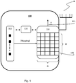
- Fig. 1 shows a transmit device 100 according to an embodiment of the present invention.
- the transmit device 100 comprises at least one logical antenna port 102 (however a plurality of logical antenna ports are shown in Fig. 1 ) and an antenna array 104 having N number of columns and M number of rows.
- the logical antenna port(s) 102 is communicably coupled to the antenna array 104 according to well known techniques known in the art.
- the number of logical antenna ports in this disclosure is denoted S , where S ⁇ 1 .
- the logical antenna port 102 is configured to provide a broadcast component signal which is intended to be mapped on the physical antenna ports of the antenna array 104. Therefore, the antenna array 104 comprises one or more antenna elements 106, and each antenna element 106 comprises at least one physical antenna port 108 (see Fig. 3 ) in one Polarization (Pol). Each antenna element 106 therefore comprises P number of physical antenna ports, where P ⁇ 1 .
- Fig. 3 more about the antenna element 106, physical antenna port 108, and polarization is shown in Fig. 3 .
- the transmit device 100 further comprises a processor 110 which is configured to control the mapping between the logical antenna port(s) and the physical antenna ports of the antenna elements.
- the processor 110 according to the present solution is configured to select Q number of columns among the N number of columns of the antenna array 104, in which Q ⁇ N .
- the processor 110 is further configured to determine a Phase Centre Location, PCL, for the logical antenna port 102.
- the phase centre location PCL is arranged in a point on a vertical axis A located in a space spanned by the Q number of columns as illustrated in Fig. 1 .
- the vertical axis A is illustrated with the dotted arrow marked A in Fig. 1 .
- the processor 110 is finally configured to map the logical antenna port 102 on the physical antenna ports of the N number of available columns based on the determined phase centre location PCL.
- the following description will more in detail explain and describe the determined phase centre location PCL.
- the antenna array 104 is configured to transmit the broadcast component signal on the mapped physical antenna ports of the Q number of columns.
- Fig. 2 shows a corresponding method 200 according to an embodiment of the present invention.
- the method 200 may be executed in a transmit device 100, such as the one shown in Fig. 1 .
- the present method 200 comprises the step of selecting 202 Q number of columns among the N number of columns, where Q ⁇ N.
- the method 200 further comprises the step of determining 204 a phase centre location PCL for the logical antenna port 102. As described above the phase centre location PCL is arranged in a point on a vertical axis A located in the Q number of columns.
- the method 200 further comprises the step of mapping 206 the logical antenna port 102 on the physical antenna ports 108a, 108b,..., 108q of the Q number of columns based on the determined phase centre location PCL.
- the method 200 finally comprises the step of transmitting 208 the broadcast component signal on the mapped physical antenna ports 108a, 108b,..., 108q of the Q number of columns.
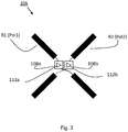
- Fig. 3 shows and illustrates an antenna element 106 of the antenna array 104 according to an embodiment of the present invention.
- the antenna element 106 in Fig. 3 includes in this particular example two physical antenna ports 108a and 108b. Each physical antenna port 108a and 108b is connected to a respective radiator R1 and R2. Each of the two radiators R1 and R2 has orthogonal polarization Pol1 and Pol2 relative to each other.
- each antenna element 106 comprises two physical antenna ports 108 in a first polarization Pol1 and in a second polarization Pol2, respectively, and the first polarization Pol1 is orthogonal to the second polarization Pol2.
- radiator R1 and R2 normally have orthogonal or close to orthogonal polarizations.
- radiator R1 has -45 degrees polarization
- radiator R2 has +45 degrees polarization.
- Fig. 3 also shows the embodiment in which each physical antenna port 108a and 108b has its own associated corresponding independent transmitter amplifier 112a and 112b, respectively.
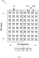
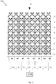
- Fig. 4 illustrates a planar Massive MIMO (MM) antenna, such as the present antenna array 104, having M x N number of antenna elements, where M denotes the number of rows of the MM, and N denotes the number of columns of the MM. Further, the MM in this embodiment also included two polarizations, Pol1 and Pol2, for each antenna element 106 of the MM. The two polarizations Pol1 and Pol2 are illustrated as crossed arrows in Fig. 4 . According to embodiments of the present invention a subset of the number of available columns N is selected and defined as subset Q . Fig. 4 also shows logical antenna ports 102a, 102b, 102c, and 102d to be mapped on the physical antenna ports of the antenna elements of the MM.
- M denotes the number of rows of the MM
- N denotes the number of columns of the MM.
- the MM in this embodiment also included two polarizations, Pol1 and Pol2, for each
- the processor 110 is further configured to generate a row wise excitation vector and a column wise excitation vector based on the determined phase centre location PCL.
- the processor 110 is further configured to excite the component broadcast signal with the row wise excitation vector and the column wise excitation vector for controlling the elevation beam and the azimuth beam, respectively, of the transmitted component broadcast signal.
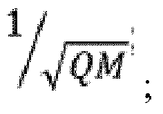
- each column of the column wise excitation vector has an amplitude that is equal to: 1 Q ; and each antenna element excitation being the combination of the row wise excitation vector and the column wise excitation vector has an amplitude that is equal to: 1 QM ; and each physical antenna port excitation being the combination of a number of physical antenna ports P per antenna element and the row wise excitation vector and the column wise excitation vector has an amplitude that is equal to: 1 QMP .
- the column wise excitation vector may be symmetric according to an embodiment of the present invention.
- the symmetry may in one example imply that that mirroring of the column wise excitation vector around its centre element results in the same vector.
- a geometric method is used for generating the elements of the column wise excitation vector based on the PCL.
- Each element of the excitation vectors comprises an amplitude component and a phase component as will be more described in the following description.
- the present geometric method may e.g. be implemented as an algorithm in the processor 110 of the transmit device 100, e.g., in the form of a software executed in the processor 110.
- the software may be configured to receive parameters as input and calculate phase and amplitude for the different physical antenna ports of the antenna array and output these calculated phases and amplitudes.
- the elements of the column wise excitation vector are generated by using a geometric method such that the phase of the transmitted component broadcast signal has a variation less than a phase threshold value within an azimuth beamwidth.
- the elements of the column wise excitation vector are generated by using a geometric method such that the amplitude of the transmitted component broadcast signal has a variation less than an amplitude threshold value within an azimuth beamwidth.
- the two above described embodiments are combined such that both the phase and the amplitude of the azimuth beamwidth are within respective threshold values.
- the phase and amplitude variation within the intended beamwidth instead needs to be designed to be within some threshold of small values. It could e.g. be reasonable to let the amplitude vary within ⁇ 1.5dB and let the phase vary within ⁇ 30 degrees.
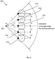
- Fig. 5 illustrates the concept of phase centre location PCL according to the present solution.
- the waves transmitted from a column subset Q of N available columns, or possibly all the N columns of the antenna array wave1, wave2,..., waveQ, will be combined in the air and generate a complex valued total radiation pattern F( ⁇ ) indicated as waveTot in Fig. 5 .
- a phase centre location PCL for the column subset Q is determined.
- Fig. 5 further describes how phase centre location PCL can be determined by choosing a number of columns Q out of the available columns N , and optimize the elements of the column wise excitation vector x 1 , x 2 , ..., x Q such that the phase front of the total radiated wave is constant or near constant within the desired wanted broadcast beamwidth.
- Each antenna element 106 of the antenna array 104 has a sector radiation pattern of 65 degrees in this particular example.
- the phase centre location PCL is located behind the third column Col. 3.
- One way to achieve this is to just let the centre antenna element of the five antenna elements be excited, i.e.
- the other antenna elements are turned off. It has been noted that the radiated phase becomes constant in all directions, which means that the radiated wave originates from the third vertical position in the antenna array 104. This configuration works, but only one of the N total available elements of the antenna array is used implying that only 1/ N of the available power is used resulting in reduced performance.
- phase centre location PCL One goal when determining the phase centre location PCL is to have the antenna elements of the column-wise excitation as equal as possible in terms of magnitude in order to make maximum possible use of the transmitter power amplifiers, and also with the goal of achieving a constant phase of F( ⁇ ) within the desired broadcast beamwidth.
- Fig. 6 shows an example when the present geometric method is applied for generating the antenna elements of the column wise excitation vector.
- Fig. 6 imagine we want to locate a PCL in the third antenna element of the five available antenna elements. This is simply done by letting only the third antenna element (106c) out of the five antenna element (106a-106d) be excited. The radiation pattern in this case originates from a phase centre location PCL located in the third antenna element 106c.
- the radiated phase will vary over the azimuth angles, which means that the radiated wave originates from another location than the third vertical position in the antenna array 104, i.e. now the phase centre location PCL is behind the first antenna element instead.
- the radiation intensity patterns for the two cases will look similar, but the radiated phase will emanate from another point than from the third antenna element.
- Fig. 7 shows yet another example when the present geometric method is applied.
- the example in Fig. 7 is the case when all five antenna elements are excited with same amplitude and phase. This time we expect the wave to be radiated from the centre antenna element, because the excitations are symmetric around the third vertical antenna element.
- the resulting calculated radiation pattern will show that the phase is indeed constant within the main beam, but that the phase rapidly is changed with 180 degrees between each side lobe.
- the main beam becomes very narrow when we use this uniform excitation (same amplitude, same phase) on all the antenna elements, which makes it unusable for broadcast coverage.
- the phase centre location PCL is though very constant within the 3 dB beamwidth. But we need to do something else to create a wider beamwidth, with a flat phase front within the beamwidth.
- ⁇ 1 32.5 degrees (to achieve a beamwidth of 65 degrees).
- the corresponding phase lengths are:
- the centre antenna element, i.e. antenna element 106c should be excited with 0 degrees phase.
- antenna element gain at 0 degrees is 7.2dBi, at 17.7 degrees it is 6.3dBi, at 32.5 degrees it is 4.2dBi according to given radiation diagrams in this particular examples.
- antenna elements 106b and 106d will need 0.9dB amplification
- antenna elements 106a and 106e will need 3dB amplification
- antenna element 106c will need 0dB (no amplification).
- ⁇ 5 65 degrees.
- r 1 0.93 ⁇
- r 2 1.05 ⁇
- r 3 1.37 ⁇
- r 4 1.76 ⁇
- r 5 2.21 ⁇
- ⁇ 1 0 degrees
- ⁇ 2 28.3 degrees
- ⁇ 3 47.1 degrees
- ⁇ 4 58.2 degrees
- ⁇ 5 65 degrees.
- the corresponding phase lengths are therefore:
- antenna element 106a should be excited with 0 degrees phase.
- antenna element 106a which has its maximum gain (7.2dBi) in the intended direction
- antenna element 106b will need 2.3dB amplification
- antenna element 106c will need 6.5dB amplification
- antenna element 106d will need 10.1dB amplification
- antenna element 106e will need 12.7dB amplification.
- Antenna element 106a will not need any amplification since it is already radiating with maximum intensity in the intended direction, so the amplification for that element is hence 0dB.
- Conversion from dB to linear scale gives that 0dB ⁇ 1 (linear amplitude), 2.3dB ⁇ 1.3 (linear amplitude), 6.5dB ⁇ 2.1 (linear amplitude), 10.1dB ⁇ 3.2 (linear amplitude), 12.7dB ⁇ 4.3 (linear amplitude).
- the corresponding amplitudes excitations for the antenna elements are hence [1, 1.3, 2.1, 3.2, 4.3] (linear amplitude) after we have compensated for weighting up the beams depending on their radiation intensity in different directions. In this example we find that the amplitudes vary much between the different antenna elements, the antenna element with highest excitation amplitude with amplitude 4.3 whilst the innermost antenna element excited with amplitude 1.
- the environment between the transmit device 100 and a receiver includes a number of scatterers, e.g. houses, trees, the ground, mountains etc., where the radiated waves from the transmit device 100 will be reflected and retransmitted towards a receiver device. If the phase centre locations PCLs for the different broadcast beams would be equal, then the distance between each phase centre location and the scatterer would also be equal, and there would be a sacrifice in the possibilities to achieve the diversity schemes available by Transmit Diversity (TD).
- TD Transmit Diversity
- phase centre locations we also enable the possibility to switch phase centre for the radio signals and thereby achieve higher diversity for these signals as well.
- the phase centre locations that can be created will in effect lead to that the MM BS behaves like a legacy Base station, transmitting wide beams with the CRS signals from distinct phase centre location points on the MM antenna aperture.
- each column wise excitation x 1 , x 2 , x 3 , ... , x Q is in turn multiplied with a row excitation y 1 , y 2 , y 3 , ... , y M , where M denotes the total number of available rows.
- each physical antenna element may have P number of physical antenna ports (normally 1 or 2 with two orthogonal polarizations).
- element excitations Z m,n that are the excitations per physical antenna port due to the combination of a column excitation x n multiplied with a row excitation y m and split on the physical antenna ports available on each physical antenna element. This makes it possible to direct the elevation beam coverage in the desired elevation direction.
- MM beamforming compared to conventional BS beamforming is that we to the largest possible extent want to use all available power of the transmitters in the vertical domain, i.e. full power, constant amplitude, in order to make maximum use of the power available in the transmitter amplifiers.
- Fig. 8 and 9 illustrate the transmit device 100 according to these embodiments.
- Fig. 8 shows the example of mapping the single logical antenna port 102a on an antenna array constituting 8(vertical ( M ))x8(horizontal ( N ))x2(polarizations ( P )) physical antenna ports. Due to the symmetry of the column wise excitations, x 1 , x 2 , x 3 , x 4 , x 4 , x 3 , x 2 , x 1 , the phase centre axis A is located in the middle of the antenna array. For Fig. 8 case both polarizations of every column get the same excitation.
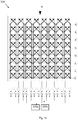
- Fig. 9 shows the example of mapping the single logical antenna port 102a on an antenna array constituting 8(vertical ( M ))x8(horizontal ( N ))x2(polarizations ( P )) physical antenna ports. Due to the symmetry of the column wise excitations, x 1 , x 2 , x 3 , x 4 , x 4 , x 3 , x 2 , x 1 , the phase centre axis A is located in the middle of the antenna array. By multiplying the second polarization with either +1 or -1, the resulting polarization for the broadcast beam could be either vertical or horizontal. For the Fig.
- Fig. 10 illustrates this embodiment.
- both polarizations of every column get the same excitation, but each polarization is dedicated to one logical antenna port.
- the column excitation vector is symmetrical in the sense that if it is mirrored both along the horizontal axis and the vertical axis, it looks the same. This is needed in order to achieve a symmetrical broadcast pattern of the beam.
- the column wise excitation vector is normalized, so that it does not add nor subtract energy relative to the broadcast signal transmitted on the logical antenna ports.
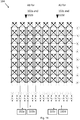
- Fig. 10 shows as mentioned above the example of mapping two logical antenna ports 102a and 102b on an antenna array constituting 8(vertical ( M ))x8(horizontal ( N ))x2(polarizations ( P )) physical antenna ports. Due to the symmetry of the column excitations, x 1 , x 2 , x 3 , x 4 , x 4 , x 3 , x 2 , x 1 , the phase centre axis A is located in the middle of the antenna array.
- each of the logical antenna ports will generate a broadcast beam with the phase centre in the middle of the antenna array and with either +45 degrees or -45 degrees polarization.
- Logical antenna ports 102a and 102b (with centre axis A1) in this example have the same subset of columns Q1, 1, 2, 3, 4, but orthogonal polarizations (i.e. +45 or -45 degrees), whereas logical antenna ports 102c and 102d (with centre axis A2) have another subset of columns Q2, 5,6,7,8, and also orthogonal polarizations (i.e. +45 or -45 degrees).
- This configuration creates orthogonality between all four logical antenna ports even if 102a, 102b and 102c, 102d pairs have the same polarizations.
- each logical antenna port For the case of having four available logical antenna ports in the transmit device 100, we aim to map each logical antenna port to one polarization in the system (Pol1, Pol2), and also map each logical antenna port on a subset Q of the available antenna columns N .
- Fig. 11 illustrates the transmit device 100. As can be seen, both polarizations of every column get the same excitation, but each polarization is dedicated to one logical antenna port 102a, 102b, 102c or 102d, and a subgroup Q1 and Q2 out of N columns.
- each antenna element 106 is coupled to a corresponding independent transmitter amplifier 112.
- MM systems One of the targets usually related with MM systems, is that instead of using one strong power amplifier feeding the complete antenna array, smaller cheaper amplifiers can be used, closely located to the physical antenna elements, so that losses can be minimized and cost can be kept down.
- MM systems comes the possibility to systemize the BS antenna in a completely new way. The complicated feeding system can be discarded and instead locate small active Radio Frequency (RF) circuits (like Power Amplifiers (PAs) and Low Noise Amplifiers (LNAs) and other circuitry) very close to the antenna elements.
- RF Radio Frequency
- PAs Power Amplifiers
- LNAs Low Noise Amplifiers
- the component broadcast signal is used as a cell specific reference signal or used in one or more broadcast signals for channels in the group comprising: Primary Synchronisation Channel, Secondary Synchronisation Channel, Physical Broadcast Channel, Physical Control Format Indicator Channel, Physical Hybrid Automatic Repeat Request Indicator Channel, and Physical Downlink Control Channel. All of these mentioned channels are used for such signals that need to be broadcasted all over the coverage cell of the transmit device 100. It is therefore important to achieve a wide beamforming in the azimuth and the elevation planes to secure that the radiation is heard in all directions where the user devices, we want to transmit to, are located.
- Fig. 12 shows an antenna array azimuth beamwidth of a solution according to an embodiment of the present invention for an antenna array having 8x8 antenna elements.
- the horizontal axis of Fig. 12 shows the phase in degrees and the vertical axis shows the gain radiation pattern in dBi.
- EIRP Effective Isotropic Radiated Power
- the effects of the present solution is that the component broadcast beams will get a much higher Effective Isotropic Radiated Power (EIRP) compared to the case where the broadcast beams are mapped to a few physical antenna ports only. For instance, if PSS/SSS signals are mapped on four columns instead of just one column, a resulting EIRP gain of 6dB is achieved.
- EIRP Effective Isotropic Radiated Power
- phase centre location PCL created by exciting a number of columns Q with a proper excitation vector [x 1 , x 2 , ,..., x Q ] leads to a radiated field F( ⁇ ), which has a constant (or nearly constant) phase over an intended broadcast beam coverage beamwidth - ⁇ BW/2 ⁇ ⁇ ⁇ ⁇ BW/2 . This further has the effect that the combined wave has low ripple and good coverage within the intended beamwidth.
- Fig. 13 illustrates an exemplary wireless communication system 500 according to an embodiment of the present invention.
- a transmit device 100 as described in this disclosure transmits broadcast component signals to a receiver device 300 in the wireless communication system 500.
- the transmit device 100 is in this example a radio network node and the receiver device 300 a User Equipment (UE).
- UE User Equipment
- the transmit device 100 may be a radio network node, or base station, e.g. a Radio Base Station (RBS), which in some networks may be referred to as transmitter, "eNB", “eNodeB”, “NodeB” or “B node”, depending on the technology and terminology used.
- the radio network nodes may be of different classes such as e.g. macro eNodeB, home eNodeB or pico base station, based on transmission power and thereby also cell size.
- the radio network node can be a Station (STA), which is any device that contains an IEEE 802.11-conformant Media Access Control (MAC) and Physical Layer (PHY) interface to the Wireless Medium (WM).
- STA Station
- MAC Media Access Control
- PHY Physical Layer
- the receiver device 300 may be a User Equipment (UE), mobile station, wireless terminal and/or mobile terminal is enabled to communicate wirelessly in a wireless communication system, sometimes also referred to as a cellular radio system.
- the User Equipment (UE) may further be referred to as mobile telephones, cellular telephones, computer tablets or laptops with wireless capability.
- the UEs in the present context may be, for example, portable, pocket-storable, hand-held, computer-comprised, or vehicle-mounted mobile devices, enabled to communicate voice and/or data, via the radio access network, with another entity, such as another receiver or a server.
- the UE can be a Station (STA), which is any device that contains an IEEE 802.11-conformant Media Access Control (MAC) and Physical Layer (PHY) interface to the Wireless Medium (WM).
- MAC Media Access Control
- PHY Physical Layer
- any method according to the present invention may be implemented in a computer program, having code means, which when run by processing means causes the processing means to execute the steps of the method.
- the computer program is included in a computer readable medium of a computer program product.
- the computer readable medium may comprises of essentially any memory, such as a ROM (Read-Only Memory), a PROM (Programmable Read-Only Memory), an EPROM (Erasable PROM), a Flash memory, an EEPROM (Electrically Erasable PROM), or a hard disk drive.
- the present first network node and second network node comprises the necessary communication capabilities in the form of e.g., functions, means, units, elements, etc., for performing the present solution.
- means, units, elements and functions are: processors, memory, buffers, control logic, encoders, decoders, rate matchers, de-rate matchers, mapping units, multipliers, decision units, selecting units, switches, interleavers, de-interleavers, modulators, demodulators, inputs, outputs, antennas, amplifiers, receiver units, transmitter units, DSPs, MSDs, TCM encoder, TCM decoder, power supply units, power feeders, communication interfaces, communication protocols, etc. which are suitably arranged together for performing the present solution.
- the processors of the present devices may comprise, e.g., one or more instances of a Central Processing Unit (CPU), a processing unit, a processing circuit, a processor, an Application Specific Integrated Circuit (ASIC), a microprocessor, or other processing logic that may interpret and execute instructions.
- CPU Central Processing Unit
- ASIC Application Specific Integrated Circuit
- the expression "processor” may thus represent a processing circuitry comprising a plurality of processing circuits, such as, e.g., any, some or all of the ones mentioned above.
- the processing circuitry may further perform data processing functions for inputting, outputting, and processing of data comprising data buffering and device control functions, such as call processing control, user interface control, or the like.
Landscapes
- Engineering & Computer Science (AREA)
- Computer Networks & Wireless Communication (AREA)
- Signal Processing (AREA)
- Physics & Mathematics (AREA)
- Mathematical Physics (AREA)
- Variable-Direction Aerials And Aerial Arrays (AREA)
Claims (14)
- Dispositif d'émission destiné à un système de communication sans fil (500), le dispositif d'émission (100) comprenant :au moins un port d'antenne logique (102) configuré pour fournir un signal de composante diffusé ;un réseau d'antennes (104) possédant un nombre M de lignes et un nombre N de colonnes d'éléments d'antenne (106a, 106b, ..., 106n), chaque élément d'antenne (106) comprenant au moins un port d'antenne physique (108) ayant une certaine polarisation ; etun processeur (110) configuré pour- sélectionner un nombre Q de colonnes parmi le nombre N de colonnes, où Q ≤ N,- déterminer un emplacement de centre de phase (PCL) pour le port d'antenne logique (102), l'emplacement de centre de phase (PCL) étant agencé en un point d'un axe vertical (A) situé dans le nombre Q de colonnes,- associer le port d'antenne logique (102) aux ports d'antenne physiques (108a, 108b, ..., 108q) du nombre Q de colonnes d'après l'emplacement de centre de phase (PCL) déterminé ;le réseau d'antennes (104) étant configuré pour émettre le signal de composante diffusé sur les ports d'antenne physiques (108a, 108b, ..., 108q) associés du nombre Q de colonnes ;dans lequel dispositif Q ≥ 2, et l'emplacement de centre de phase (PCL) se trouve sur l'axe central (A) du nombre Q de colonnes.
- Dispositif d'émission (100) selon la revendication 1, dans lequel chaque élément d'antenne (106) comprend deux ports d'antenne physiques (108) ayant une première polarisation et une deuxième polarisation, respectivement, la première polarisation étant orthogonale à la deuxième polarisation.
- Dispositif d'émission (100) selon la revendication 1 ou 2, le dispositif d'émission (100) comprenant un port d'antenne logique (102), avec Q = N.
- Dispositif d'émission (100) selon la revendication 1 ou 2, le dispositif d'émission (100) comprenant deux ports d'antenne logiques (102a, 102b), avec Q = N, et dans lequel dispositif un port d'antenne logique (102a) est associé aux ports d'antenne physiques ayant la première polarisation et l'autre port d'antenne logique (102b) est associé aux ports d'antenne physiques ayant la deuxième polarisation.
- Dispositif d'émission (100) selon l'une quelconque des revendications précédentes, dans lequel le processeur (110) est également configuré pour
générer un vecteur d'excitation dans le sens des lignes et un vecteur d'excitation dans le sens des colonnes reposant sur l'emplacement de centre de phase (PCL),
exciter le signal de diffusion de composante avec le vecteur d'excitation dans le sens des lignes et le vecteur d'excitation dans le sens des colonnes pour commander le faisceau d'élévation et le faisceau d'azimut, respectivement, du signal de diffusion de composante émis. - Dispositif d'émission (100) selon la revendication 5, dans lequel chaque colonne du vecteur d'excitation dans le sens des colonnes a une amplitude qui est égale à :


- Dispositif d'émission (100) selon la revendication 5 ou 6, dans lequel le vecteur d'excitation dans le sens des colonnes est symétrique.
- Dispositif d'émission (100) selon l'une quelconque des revendications 5 à 7, dans lequel les éléments du vecteur d'excitation dans le sens des colonnes sont générés au moyen d'un procédé géométrique qui est tel que la phase du signal de diffusion de composante émis présente une variation inférieure à une valeur de seuil de phase à l'intérieur d'une largeur de faisceau d'azimut.
- Dispositif d'émission (100) selon l'une quelconque des revendications 5 à 8, dans lequel les éléments du vecteur d'excitation dans le sens des colonnes sont générés au moyen d'un procédé géométrique qui est tel que l'amplitude du signal de diffusion de composante émis présente une variation inférieure à une valeur de seuil d'amplitude à l'intérieur d'une largeur de faisceau d'azimut.
- Dispositif d'émission (100) selon la revendication 8 ou 9, dans lequel le procédé géométrique repose sur un ou plusieurs paramètres du groupe comprenant : des caractéristiques de rayonnement concernant les éléments d'antenne (106a, 106b, ..., 106n), la distance spatiale entre les éléments d'antenne (106a, 106b, ..., 106n), la fréquence du signal de diffusion de composante émis, et la largeur de faisceau d'azimut souhaitée pour le signal de composante diffusé émis.
- Dispositif d'émission (100) selon l'une quelconque des revendications précédentes, dans lequel chaque port d'antenne physique (108) est couplé à un amplificateur d'émetteur (112) indépendant correspondant.
- Dispositif d'émission (100) selon l'une quelconque des revendications précédentes, dans lequel le signal de diffusion de composante est utilisé comme signal de référence spécifique à une cellule ou est utilisé dans un ou plusieurs signaux de diffusion destinés à des canaux du groupe comprenant : un canal de synchronisation primaire, un canal de synchronisation secondaire, un canal de diffusion physique, un canal d'indicateur de format de commande physique, un canal d'indicateur de demande de répétition automatique hybride physique, et un canal de commande de liaison descendante physique.
- Procédé pour dispositif d'émission (100), comprenant
au moins un port d'antenne logique (102) configuré pour fournir un signal de composante diffusé ;
un réseau d'antennes (104) possédant un nombre M de lignes et un nombre N de colonnes d'éléments d'antenne (106a, 106b, ..., 106n), chaque élément d'antenne (106) comprenant au moins un port d'antenne physique (108) ayant une certaine polarisation ; et
le procédé (200) comprenant les étapes consistant àsélectionner (202) un nombre Q de colonnes parmi le nombre N de colonnes, où Q≤N,déterminer (204) un emplacement de centre de phase (PCL) pour le port d'antenne logique (102), l'emplacement de centre de phase (PCL) étant agencé en un point d'un axe vertical (A) situé dans le nombre Q de colonnes,associer (206) le port d'antenne logique (102) aux ports d'antenne physiques (108a, 108b, ..., 108q) du nombre Q de colonnes d'après l'emplacement de centre de phase (PCL) déterminé,émettre (208) le signal de composante diffusé sur les ports d'antenne physiques (108a, 108b, ..., 108q) associés du nombre Q de colonnes ;dans lequel procédé Q ≥ 2, et l'emplacement de centre de phase (PCL) se trouve sur l'axe central (A) du nombre Q de colonnes. - Programme informatique comprenant un code de programme servant à mettre en oeuvre un procédé selon la revendication 13 lorsque le programme informatique s'exécute sur un ordinateur.
Applications Claiming Priority (1)
| Application Number | Priority Date | Filing Date | Title |
|---|---|---|---|
| PCT/EP2015/061963 WO2016192750A1 (fr) | 2015-05-29 | 2015-05-29 | Dispositif d'émission et procédé associé |
Publications (2)
| Publication Number | Publication Date |
|---|---|
| EP3292636A1 EP3292636A1 (fr) | 2018-03-14 |
| EP3292636B1 true EP3292636B1 (fr) | 2019-08-07 |
Family
ID=53276131
Family Applications (1)
| Application Number | Title | Priority Date | Filing Date |
|---|---|---|---|
| EP15726132.2A Active EP3292636B1 (fr) | 2015-05-29 | 2015-05-29 | Dispositif d'émission et procédé associé |
Country Status (4)
| Country | Link |
|---|---|
| US (1) | US10249961B2 (fr) |
| EP (1) | EP3292636B1 (fr) |
| CN (1) | CN107667480B (fr) |
| WO (1) | WO2016192750A1 (fr) |
Families Citing this family (5)
| Publication number | Priority date | Publication date | Assignee | Title |
|---|---|---|---|---|
| CN110024218B (zh) * | 2016-12-08 | 2020-06-16 | 华为技术有限公司 | 用于生成广播波束的装置、方法以及计算机程序 |
| US20200145265A1 (en) * | 2018-11-01 | 2020-05-07 | The United States Of America As Represented By The Secretary Of The Navy | Device, Method, And System For Obscuring A Transmitted Radio Frequency Signal Using Polarization Modulation To Avoid Interception |
| KR102502768B1 (ko) * | 2018-11-16 | 2023-02-22 | 한국전자통신연구원 | 초고주파 기반의 액세스 네트워크 운용 방법, 및 이를 위한 장치 |
| US10812167B2 (en) * | 2018-11-16 | 2020-10-20 | Electronics And Telecommunications Research Institute | Method for operating very high frequency based access network, and apparatus for the same |
| CN109586774B (zh) * | 2018-12-28 | 2021-07-23 | 安徽中瑞通信科技股份有限公司 | 一种5g阵列天线的控制系统 |
Family Cites Families (13)
| Publication number | Priority date | Publication date | Assignee | Title |
|---|---|---|---|---|
| US7317427B2 (en) * | 2005-01-25 | 2008-01-08 | Raytheon Company | Adaptive array |
| CN102148634B (zh) * | 2010-02-08 | 2013-12-25 | 电信科学技术研究院 | 天线发射分集的方法及系统 |
| EP2539959B1 (fr) * | 2010-02-25 | 2014-02-12 | Telefonaktiebolaget LM Ericsson (publ) | Noeud de système de communication comportant matrice de transformation |
| WO2011103919A1 (fr) * | 2010-02-25 | 2011-09-01 | Telefonaktiebolaget L M Ericsson (Publ) | Nœud de système de communication comportant réseau de reconfiguration |
| US20130057432A1 (en) | 2011-09-02 | 2013-03-07 | Samsung Electronics Co., Ltd. | Method and apparatus for beam broadening for phased antenna arrays using multi-beam sub-arrays |
| US20130286960A1 (en) | 2012-04-30 | 2013-10-31 | Samsung Electronics Co., Ltd | Apparatus and method for control channel beam management in a wireless system with a large number of antennas |
| CN103391128B (zh) * | 2012-05-07 | 2017-08-18 | 华为技术有限公司 | 一种虚拟天线映射方法及装置 |
| CN102833235B (zh) | 2012-08-13 | 2016-04-27 | 鹤山世达光电科技有限公司 | 身份认证管理装置 |
| CN103812546B (zh) * | 2012-11-07 | 2017-08-25 | 华为技术有限公司 | 一种基于天线阵列的参考信号映射方法、装置及系统 |
| US8976884B2 (en) * | 2012-12-20 | 2015-03-10 | Google Technology Holdings LLC | Method and apparatus for antenna array channel feedback |
| US9509387B2 (en) * | 2013-06-24 | 2016-11-29 | Telefonaktiebolaget Lm Ericsson (Publ) | Node in a wireless communication system where antenna beams match the sector width |
| CN103840872B (zh) * | 2014-03-07 | 2017-06-06 | 华为技术有限公司 | 生成天线的权值的装置、方法和维护管理设备 |
| WO2015169366A1 (fr) * | 2014-05-08 | 2015-11-12 | Telefonaktiebolaget L M Ericsson (Publ) | Formation de faisceau au moyen d'un agencement d'antennes |
-
2015
- 2015-05-29 CN CN201580080531.9A patent/CN107667480B/zh active Active
- 2015-05-29 WO PCT/EP2015/061963 patent/WO2016192750A1/fr not_active Ceased
- 2015-05-29 EP EP15726132.2A patent/EP3292636B1/fr active Active
-
2017
- 2017-11-29 US US15/825,302 patent/US10249961B2/en active Active
Non-Patent Citations (1)
| Title |
|---|
| None * |
Also Published As
| Publication number | Publication date |
|---|---|
| US10249961B2 (en) | 2019-04-02 |
| CN107667480B (zh) | 2020-10-16 |
| EP3292636A1 (fr) | 2018-03-14 |
| US20180090853A1 (en) | 2018-03-29 |
| CN107667480A (zh) | 2018-02-06 |
| WO2016192750A1 (fr) | 2016-12-08 |
Similar Documents
| Publication | Publication Date | Title |
|---|---|---|
| CN102714805B (zh) | 天线系统 | |
| US11005546B2 (en) | Antenna system, signal processing system, and signal processing method | |
| US11569575B2 (en) | Low-complexity beam steering in array apertures | |
| US9042276B1 (en) | Multiple co-located multi-user-MIMO access points | |
| US8482478B2 (en) | MIMO antenna system | |
| US9537204B2 (en) | Multi-channel multi-sector smart antenna system | |
| US10249961B2 (en) | Transmit device and method thereof | |
| US11329399B2 (en) | Antenna arrangement for dual-polarization beamforming | |
| US20210099222A1 (en) | Beamforming Architecture For Multi-Beam Multiple-Input-Multiple-Output (MIMO) | |
| US11303040B2 (en) | Conformal phased arrays | |
| US11276941B2 (en) | Broadband antenna | |
| CN109067439B (zh) | 一种数字多波束阵发射装置采用的测试方法 | |
| US6697643B1 (en) | System and method for implementing a multi-beam antenna without duplex filters within a base station | |
| Gotsis et al. | Beamforming in 3G and 4G mobile communications: the switched-beam approach | |
| EP4289026B1 (fr) | Réseau antennaire ayant une géométrie de réseau antennaire reconfigurable | |
| Gautam et al. | Beamforming investigation for wireless communication at 60 GHz | |
| US11005559B2 (en) | Repeater and radiation pattern forming method for the same | |
| Mörlein et al. | Beamforming comparison of a multi-mode array with a dipole array of the same aperture size | |
| CN117578097A (zh) | 二维相控阵天线 | |
| CN206807453U (zh) | 用于用户终端的信号收发装置、用户终端 | |
| Zetik et al. | Antenna array configurations for terrestrial backhaul links at Ka-band frequencies | |
| JP2024052187A (ja) | 受電装置、受信装置、端末装置、無線電力伝送システム及び通信システム |
Legal Events
| Date | Code | Title | Description |
|---|---|---|---|
| STAA | Information on the status of an ep patent application or granted ep patent |
Free format text: STATUS: THE INTERNATIONAL PUBLICATION HAS BEEN MADE |
|
| PUAI | Public reference made under article 153(3) epc to a published international application that has entered the european phase |
Free format text: ORIGINAL CODE: 0009012 |
|
| STAA | Information on the status of an ep patent application or granted ep patent |
Free format text: STATUS: REQUEST FOR EXAMINATION WAS MADE |
|
| 17P | Request for examination filed |
Effective date: 20171204 |
|
| AK | Designated contracting states |
Kind code of ref document: A1 Designated state(s): AL AT BE BG CH CY CZ DE DK EE ES FI FR GB GR HR HU IE IS IT LI LT LU LV MC MK MT NL NO PL PT RO RS SE SI SK SM TR |
|
| AX | Request for extension of the european patent |
Extension state: BA ME |
|
| DAV | Request for validation of the european patent (deleted) | ||
| DAX | Request for extension of the european patent (deleted) | ||
| STAA | Information on the status of an ep patent application or granted ep patent |
Free format text: STATUS: EXAMINATION IS IN PROGRESS |
|
| 17Q | First examination report despatched |
Effective date: 20181115 |
|
| REG | Reference to a national code |
Ref country code: DE Ref legal event code: R079 Ref document number: 602015035227 Country of ref document: DE Free format text: PREVIOUS MAIN CLASS: H04B0007040000 Ipc: H04B0007045600 |
|
| GRAP | Despatch of communication of intention to grant a patent |
Free format text: ORIGINAL CODE: EPIDOSNIGR1 |
|
| STAA | Information on the status of an ep patent application or granted ep patent |
Free format text: STATUS: GRANT OF PATENT IS INTENDED |
|
| RIC1 | Information provided on ipc code assigned before grant |
Ipc: H04B 7/0456 20170101AFI20190207BHEP Ipc: H04B 7/10 20170101ALN20190207BHEP Ipc: H04B 7/04 20170101ALI20190207BHEP Ipc: H01Q 9/04 20060101ALI20190207BHEP |
|
| RIC1 | Information provided on ipc code assigned before grant |
Ipc: H04B 7/0456 20170101AFI20190211BHEP Ipc: H04B 7/04 20170101ALI20190211BHEP Ipc: H01Q 9/04 20060101ALI20190211BHEP Ipc: H04B 7/10 20170101ALN20190211BHEP |
|
| INTG | Intention to grant announced |
Effective date: 20190225 |
|
| GRAS | Grant fee paid |
Free format text: ORIGINAL CODE: EPIDOSNIGR3 |
|
| GRAA | (expected) grant |
Free format text: ORIGINAL CODE: 0009210 |
|
| STAA | Information on the status of an ep patent application or granted ep patent |
Free format text: STATUS: THE PATENT HAS BEEN GRANTED |
|
| AK | Designated contracting states |
Kind code of ref document: B1 Designated state(s): AL AT BE BG CH CY CZ DE DK EE ES FI FR GB GR HR HU IE IS IT LI LT LU LV MC MK MT NL NO PL PT RO RS SE SI SK SM TR |
|
| REG | Reference to a national code |
Ref country code: GB Ref legal event code: FG4D |
|
| REG | Reference to a national code |
Ref country code: CH Ref legal event code: EP Ref country code: AT Ref legal event code: REF Ref document number: 1165416 Country of ref document: AT Kind code of ref document: T Effective date: 20190815 |
|
| REG | Reference to a national code |
Ref country code: DE Ref legal event code: R096 Ref document number: 602015035227 Country of ref document: DE |
|
| REG | Reference to a national code |
Ref country code: IE Ref legal event code: FG4D |
|
| REG | Reference to a national code |
Ref country code: NL Ref legal event code: MP Effective date: 20190807 |
|
| REG | Reference to a national code |
Ref country code: LT Ref legal event code: MG4D |
|
| PG25 | Lapsed in a contracting state [announced via postgrant information from national office to epo] |
Ref country code: SE Free format text: LAPSE BECAUSE OF FAILURE TO SUBMIT A TRANSLATION OF THE DESCRIPTION OR TO PAY THE FEE WITHIN THE PRESCRIBED TIME-LIMIT Effective date: 20190807 Ref country code: NL Free format text: LAPSE BECAUSE OF FAILURE TO SUBMIT A TRANSLATION OF THE DESCRIPTION OR TO PAY THE FEE WITHIN THE PRESCRIBED TIME-LIMIT Effective date: 20190807 Ref country code: BG Free format text: LAPSE BECAUSE OF FAILURE TO SUBMIT A TRANSLATION OF THE DESCRIPTION OR TO PAY THE FEE WITHIN THE PRESCRIBED TIME-LIMIT Effective date: 20191107 Ref country code: NO Free format text: LAPSE BECAUSE OF FAILURE TO SUBMIT A TRANSLATION OF THE DESCRIPTION OR TO PAY THE FEE WITHIN THE PRESCRIBED TIME-LIMIT Effective date: 20191107 Ref country code: LT Free format text: LAPSE BECAUSE OF FAILURE TO SUBMIT A TRANSLATION OF THE DESCRIPTION OR TO PAY THE FEE WITHIN THE PRESCRIBED TIME-LIMIT Effective date: 20190807 Ref country code: PT Free format text: LAPSE BECAUSE OF FAILURE TO SUBMIT A TRANSLATION OF THE DESCRIPTION OR TO PAY THE FEE WITHIN THE PRESCRIBED TIME-LIMIT Effective date: 20191209 Ref country code: HR Free format text: LAPSE BECAUSE OF FAILURE TO SUBMIT A TRANSLATION OF THE DESCRIPTION OR TO PAY THE FEE WITHIN THE PRESCRIBED TIME-LIMIT Effective date: 20190807 Ref country code: FI Free format text: LAPSE BECAUSE OF FAILURE TO SUBMIT A TRANSLATION OF THE DESCRIPTION OR TO PAY THE FEE WITHIN THE PRESCRIBED TIME-LIMIT Effective date: 20190807 |
|
| REG | Reference to a national code |
Ref country code: AT Ref legal event code: MK05 Ref document number: 1165416 Country of ref document: AT Kind code of ref document: T Effective date: 20190807 |
|
| PG25 | Lapsed in a contracting state [announced via postgrant information from national office to epo] |
Ref country code: LV Free format text: LAPSE BECAUSE OF FAILURE TO SUBMIT A TRANSLATION OF THE DESCRIPTION OR TO PAY THE FEE WITHIN THE PRESCRIBED TIME-LIMIT Effective date: 20190807 Ref country code: RS Free format text: LAPSE BECAUSE OF FAILURE TO SUBMIT A TRANSLATION OF THE DESCRIPTION OR TO PAY THE FEE WITHIN THE PRESCRIBED TIME-LIMIT Effective date: 20190807 Ref country code: AL Free format text: LAPSE BECAUSE OF FAILURE TO SUBMIT A TRANSLATION OF THE DESCRIPTION OR TO PAY THE FEE WITHIN THE PRESCRIBED TIME-LIMIT Effective date: 20190807 Ref country code: ES Free format text: LAPSE BECAUSE OF FAILURE TO SUBMIT A TRANSLATION OF THE DESCRIPTION OR TO PAY THE FEE WITHIN THE PRESCRIBED TIME-LIMIT Effective date: 20190807 Ref country code: IS Free format text: LAPSE BECAUSE OF FAILURE TO SUBMIT A TRANSLATION OF THE DESCRIPTION OR TO PAY THE FEE WITHIN THE PRESCRIBED TIME-LIMIT Effective date: 20191207 Ref country code: GR Free format text: LAPSE BECAUSE OF FAILURE TO SUBMIT A TRANSLATION OF THE DESCRIPTION OR TO PAY THE FEE WITHIN THE PRESCRIBED TIME-LIMIT Effective date: 20191108 |
|
| PG25 | Lapsed in a contracting state [announced via postgrant information from national office to epo] |
Ref country code: TR Free format text: LAPSE BECAUSE OF FAILURE TO SUBMIT A TRANSLATION OF THE DESCRIPTION OR TO PAY THE FEE WITHIN THE PRESCRIBED TIME-LIMIT Effective date: 20190807 |
|
| PG25 | Lapsed in a contracting state [announced via postgrant information from national office to epo] |
Ref country code: AT Free format text: LAPSE BECAUSE OF FAILURE TO SUBMIT A TRANSLATION OF THE DESCRIPTION OR TO PAY THE FEE WITHIN THE PRESCRIBED TIME-LIMIT Effective date: 20190807 Ref country code: RO Free format text: LAPSE BECAUSE OF FAILURE TO SUBMIT A TRANSLATION OF THE DESCRIPTION OR TO PAY THE FEE WITHIN THE PRESCRIBED TIME-LIMIT Effective date: 20190807 Ref country code: PL Free format text: LAPSE BECAUSE OF FAILURE TO SUBMIT A TRANSLATION OF THE DESCRIPTION OR TO PAY THE FEE WITHIN THE PRESCRIBED TIME-LIMIT Effective date: 20190807 Ref country code: EE Free format text: LAPSE BECAUSE OF FAILURE TO SUBMIT A TRANSLATION OF THE DESCRIPTION OR TO PAY THE FEE WITHIN THE PRESCRIBED TIME-LIMIT Effective date: 20190807 Ref country code: DK Free format text: LAPSE BECAUSE OF FAILURE TO SUBMIT A TRANSLATION OF THE DESCRIPTION OR TO PAY THE FEE WITHIN THE PRESCRIBED TIME-LIMIT Effective date: 20190807 |
|
| PG25 | Lapsed in a contracting state [announced via postgrant information from national office to epo] |
Ref country code: SM Free format text: LAPSE BECAUSE OF FAILURE TO SUBMIT A TRANSLATION OF THE DESCRIPTION OR TO PAY THE FEE WITHIN THE PRESCRIBED TIME-LIMIT Effective date: 20190807 Ref country code: IS Free format text: LAPSE BECAUSE OF FAILURE TO SUBMIT A TRANSLATION OF THE DESCRIPTION OR TO PAY THE FEE WITHIN THE PRESCRIBED TIME-LIMIT Effective date: 20200224 Ref country code: CZ Free format text: LAPSE BECAUSE OF FAILURE TO SUBMIT A TRANSLATION OF THE DESCRIPTION OR TO PAY THE FEE WITHIN THE PRESCRIBED TIME-LIMIT Effective date: 20190807 Ref country code: SK Free format text: LAPSE BECAUSE OF FAILURE TO SUBMIT A TRANSLATION OF THE DESCRIPTION OR TO PAY THE FEE WITHIN THE PRESCRIBED TIME-LIMIT Effective date: 20190807 |
|
| REG | Reference to a national code |
Ref country code: DE Ref legal event code: R097 Ref document number: 602015035227 Country of ref document: DE |
|
| PLBE | No opposition filed within time limit |
Free format text: ORIGINAL CODE: 0009261 |
|
| STAA | Information on the status of an ep patent application or granted ep patent |
Free format text: STATUS: NO OPPOSITION FILED WITHIN TIME LIMIT |
|
| PG2D | Information on lapse in contracting state deleted |
Ref country code: IS |
|
| 26N | No opposition filed |
Effective date: 20200603 |
|
| PG25 | Lapsed in a contracting state [announced via postgrant information from national office to epo] |
Ref country code: SI Free format text: LAPSE BECAUSE OF FAILURE TO SUBMIT A TRANSLATION OF THE DESCRIPTION OR TO PAY THE FEE WITHIN THE PRESCRIBED TIME-LIMIT Effective date: 20190807 |
|
| PG25 | Lapsed in a contracting state [announced via postgrant information from national office to epo] |
Ref country code: LI Free format text: LAPSE BECAUSE OF NON-PAYMENT OF DUE FEES Effective date: 20200531 Ref country code: CH Free format text: LAPSE BECAUSE OF NON-PAYMENT OF DUE FEES Effective date: 20200531 Ref country code: MC Free format text: LAPSE BECAUSE OF FAILURE TO SUBMIT A TRANSLATION OF THE DESCRIPTION OR TO PAY THE FEE WITHIN THE PRESCRIBED TIME-LIMIT Effective date: 20190807 |
|
| REG | Reference to a national code |
Ref country code: BE Ref legal event code: MM Effective date: 20200531 |
|
| GBPC | Gb: european patent ceased through non-payment of renewal fee |
Effective date: 20200529 |
|
| PG25 | Lapsed in a contracting state [announced via postgrant information from national office to epo] |
Ref country code: LU Free format text: LAPSE BECAUSE OF NON-PAYMENT OF DUE FEES Effective date: 20200529 |
|
| PG25 | Lapsed in a contracting state [announced via postgrant information from national office to epo] |
Ref country code: GB Free format text: LAPSE BECAUSE OF NON-PAYMENT OF DUE FEES Effective date: 20200529 Ref country code: IE Free format text: LAPSE BECAUSE OF NON-PAYMENT OF DUE FEES Effective date: 20200529 Ref country code: FR Free format text: LAPSE BECAUSE OF NON-PAYMENT OF DUE FEES Effective date: 20200531 |
|
| PG25 | Lapsed in a contracting state [announced via postgrant information from national office to epo] |
Ref country code: BE Free format text: LAPSE BECAUSE OF NON-PAYMENT OF DUE FEES Effective date: 20200531 |
|
| PG25 | Lapsed in a contracting state [announced via postgrant information from national office to epo] |
Ref country code: MT Free format text: LAPSE BECAUSE OF FAILURE TO SUBMIT A TRANSLATION OF THE DESCRIPTION OR TO PAY THE FEE WITHIN THE PRESCRIBED TIME-LIMIT Effective date: 20190807 Ref country code: CY Free format text: LAPSE BECAUSE OF FAILURE TO SUBMIT A TRANSLATION OF THE DESCRIPTION OR TO PAY THE FEE WITHIN THE PRESCRIBED TIME-LIMIT Effective date: 20190807 |
|
| PG25 | Lapsed in a contracting state [announced via postgrant information from national office to epo] |
Ref country code: MK Free format text: LAPSE BECAUSE OF FAILURE TO SUBMIT A TRANSLATION OF THE DESCRIPTION OR TO PAY THE FEE WITHIN THE PRESCRIBED TIME-LIMIT Effective date: 20190807 |
|
| PGFP | Annual fee paid to national office [announced via postgrant information from national office to epo] |
Ref country code: DE Payment date: 20250402 Year of fee payment: 11 |
|
| PGFP | Annual fee paid to national office [announced via postgrant information from national office to epo] |
Ref country code: IT Payment date: 20250422 Year of fee payment: 11 |