EP3292676B1 - Équilibrage des charges intelligent et enregistreurs de réseau intelligents à haute vitesse - Google Patents
Équilibrage des charges intelligent et enregistreurs de réseau intelligents à haute vitesse Download PDFInfo
- Publication number
- EP3292676B1 EP3292676B1 EP16790048.9A EP16790048A EP3292676B1 EP 3292676 B1 EP3292676 B1 EP 3292676B1 EP 16790048 A EP16790048 A EP 16790048A EP 3292676 B1 EP3292676 B1 EP 3292676B1
- Authority
- EP
- European Patent Office
- Prior art keywords
- flow
- node
- packet
- record
- network
- Prior art date
- Legal status (The legal status is an assumption and is not a legal conclusion. Google has not performed a legal analysis and makes no representation as to the accuracy of the status listed.)
- Active
Links
Images


Classifications
-
- G—PHYSICS
- G06—COMPUTING OR CALCULATING; COUNTING
- G06F—ELECTRIC DIGITAL DATA PROCESSING
- G06F13/00—Interconnection of, or transfer of information or other signals between, memories, input/output devices or central processing units
- G06F13/38—Information transfer, e.g. on bus
- G06F13/40—Bus structure
- G06F13/4063—Device-to-bus coupling
- G06F13/4068—Electrical coupling
-
- G—PHYSICS
- G06—COMPUTING OR CALCULATING; COUNTING
- G06F—ELECTRIC DIGITAL DATA PROCESSING
- G06F13/00—Interconnection of, or transfer of information or other signals between, memories, input/output devices or central processing units
- G06F13/38—Information transfer, e.g. on bus
- G06F13/40—Bus structure
- G06F13/4004—Coupling between buses
- G06F13/4022—Coupling between buses using switching circuits, e.g. switching matrix, connection or expansion network
-
- G—PHYSICS
- G06—COMPUTING OR CALCULATING; COUNTING
- G06F—ELECTRIC DIGITAL DATA PROCESSING
- G06F13/00—Interconnection of, or transfer of information or other signals between, memories, input/output devices or central processing units
- G06F13/38—Information transfer, e.g. on bus
- G06F13/42—Bus transfer protocol, e.g. handshake; Synchronisation
- G06F13/4282—Bus transfer protocol, e.g. handshake; Synchronisation on a serial bus, e.g. I2C bus, SPI bus
-
- H—ELECTRICITY
- H04—ELECTRIC COMMUNICATION TECHNIQUE
- H04L—TRANSMISSION OF DIGITAL INFORMATION, e.g. TELEGRAPHIC COMMUNICATION
- H04L43/00—Arrangements for monitoring or testing data switching networks
- H04L43/02—Capturing of monitoring data
- H04L43/026—Capturing of monitoring data using flow identification
-
- H—ELECTRICITY
- H04—ELECTRIC COMMUNICATION TECHNIQUE
- H04L—TRANSMISSION OF DIGITAL INFORMATION, e.g. TELEGRAPHIC COMMUNICATION
- H04L43/00—Arrangements for monitoring or testing data switching networks
- H04L43/10—Active monitoring, e.g. heartbeat, ping or trace-route
- H04L43/106—Active monitoring, e.g. heartbeat, ping or trace-route using time related information in packets, e.g. by adding timestamps
-
- H—ELECTRICITY
- H04—ELECTRIC COMMUNICATION TECHNIQUE
- H04L—TRANSMISSION OF DIGITAL INFORMATION, e.g. TELEGRAPHIC COMMUNICATION
- H04L63/00—Network architectures or network communication protocols for network security
- H04L63/14—Network architectures or network communication protocols for network security for detecting or protecting against malicious traffic
- H04L63/1408—Network architectures or network communication protocols for network security for detecting or protecting against malicious traffic by monitoring network traffic
- H04L63/1425—Traffic logging, e.g. anomaly detection
-
- Y—GENERAL TAGGING OF NEW TECHNOLOGICAL DEVELOPMENTS; GENERAL TAGGING OF CROSS-SECTIONAL TECHNOLOGIES SPANNING OVER SEVERAL SECTIONS OF THE IPC; TECHNICAL SUBJECTS COVERED BY FORMER USPC CROSS-REFERENCE ART COLLECTIONS [XRACs] AND DIGESTS
- Y02—TECHNOLOGIES OR APPLICATIONS FOR MITIGATION OR ADAPTATION AGAINST CLIMATE CHANGE
- Y02D—CLIMATE CHANGE MITIGATION TECHNOLOGIES IN INFORMATION AND COMMUNICATION TECHNOLOGIES [ICT], I.E. INFORMATION AND COMMUNICATION TECHNOLOGIES AIMING AT THE REDUCTION OF THEIR OWN ENERGY USE
- Y02D30/00—Reducing energy consumption in communication networks
- Y02D30/50—Reducing energy consumption in communication networks in wire-line communication networks, e.g. low power modes or reduced link rate
Definitions
- WO 2015/052171 A1 discloses methods, systems, and apparatus for network monitoring and analytics.
- the methods, systems, and apparatus for network monitoring and analytics perform highly probable identification of related messages using one or more sparse hash function sets. Highly probable identification of related messages enables a network monitoring and analytics system to trace the trajectory of a message traversing the network and measure the delay for the message between observation points.
- the sparse hash function value, or identity enables a network monitoring and analytics system to identify the transit path, transit time, entry point, exit point, and/or other information about individual packets and to identify bottlenecks, broken paths, lost data, and other network analytics by aggregating individual message data.
- Other related technology is shown in US 2004/117037 A1 or US 2015/071072 A1 .
- the data center computer network 100A may include, without limitation, a router 168, a firewall 166, a tap 400, an intelligent load balancer (ILB) 801, a high speed intelligent network recorder (HSINR) 170, netflow generators 180A-180D, netflow collectors (NFCs) 162A-162D, a central NFC 164, a network switch 110A, one or more servers 112A-112B, one or more tiered storage appliances 114A-114B, one or more storage array appliances 116A-116B, and one or more flash appliances 118 coupled together by one or more high speed networking cables (e.g., Ethernet wired cables 111A-111B, Fibre Channel optical cables 113A-113G) to form a local computer network 101A, often referred to as a local area network (LAN) 101A.
- LAN local area network
- the local computer network 101A To store ingress and egress network internet protocol (IP) packets (e.g., Ethernet packets) between the computer network 101A and the internet cloud (wide area network) 102, the local computer network 101A includes a high speed intelligent network recorder (HSINR) 170. To balance the load of storing packets into a plurality of storage devices in the HSINR 170, the network 101 includes the intelligent load balancer (ILB) 801. To analyze the stored packets, the HSINR 170 may couple to an analyzer 156L that provides a query agent. Alternatively, a query agent may be included as part of the ILB 801.
- IP internet protocol
- ILB intelligent load balancer
- Each NGA 180A-180D is coupled to the tap 400 to receive ingress and egress IP packets.
- Each NGA 180A-180D may be coupled to the switch 110A.
- Each NGA 180A-180D analyzes the ingress and egress IP packets it receives and generate netflow records that summarize a computer communication between IP addresses.
- the netflow records may be routed to a plurality of NFCs 162A-162D.
- Each NFC 162A-162D is coupled to the network switch 110A and the central NFC 164 that can merge netflow records together.
- a pair of computer servers 112A-112B are connected to the network switch 110A via Ethernet cables 111A-111B terminating in Ethernet cards 120A-120B installed on the servers 112A-112B to communicate using an Ethernet communication protocol.
- the computer servers 112A-112B may further have Fibre Channel host bus adapter cards 122A-122B respectively installed into them to communicate using a Fibre Channel communication protocol.
- a target network device (also referred to herein as a storage target) includes Fibre Channel cards 124A-124C installed to receive signals, including a storage request, from the servers 112A-112B off of wires or cables, such as Fibre Channel cables 113C-113D.
- the target network device may be one of the tiered storage arrays 114A-114B, the storage arrays 116A-116B, or the flash appliance 118 (referred to collectively as storage array appliances).
- Fibre Channel cards 124A, 124B, 124E, 124F, and 124G may be installed in the storage array appliances 114A, 114B, 116A-116B and 118.
- the servers 112A-112B have Fibre Channel host bus adapters 122A- 122B that are coupled to the Fibre Channel cards 124A-124C, 124D-124G in the storage array appliances 114A-114B, 116A-116B and 118.
- the Fibre Channel host adapters 122A-122B may differ somewhat from the Fibre Channel cards 124A-124B, 124E-124G because the server 112A,112B is an initiator and the storage array appliances 114A-114B, 116A-116B, 118 are targets.
- the connections between servers 112A-112B and the storage array appliances 114A, 114B, 116A, and 116B are via fiber cables 113A, 113B, 113E, 113F, and 113G that terminate at one end at the Fibre Channel cards 118,124A, 124B, 124C, 124E, 124F, and 124G of the storage array appliances 114A, 114B, 116A and 116B.
- One or more clients 150A-150N in a client-server network 100A may interface with the local computer network (data center) 101A over a wide area network (WAN) 102, such as the Internet or World Wide Web.
- the one or more clients 150A-150N may desire one or more server functions of the servers 112A-112B for software applications and/or storage capacity provided by the storage arrays or appliances 114A-114B, 116A-116B, 118 to store data.
- Servers/storage arrays in the data center 101A can communicate with the one or more remotely located clients 150A-150N over the WAN 102.
- One or more malicious clients 152A-152N may pose a security threat to the data center computer network 100A.
- a user e.g., network administrator
- a local analyzer 156L may be coupled to the HSINR 170 or to the one or more NFCs 162A-162D, 164.
- a management console 158 including a monitor and a keyboard may be coupled to the local analyzer 156L from which the computer network can be managed by a user.
- the user can manage security of the data center computer network 100A remotely over the Internet cloud 102.
- the user can manage security of the data center computer network 100A via tools, such as a remote analyzer tool 156R and a remote management console 154, including a monitor and keyboard.
- tools such as a remote analyzer tool 156R and a remote management console 154, including a monitor and keyboard.
- the remote analyzer 156R and the remote management console 154 are in communication with the one or more NFCs 162A-162D, 164 and/or the HSINR 170.
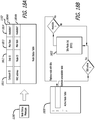
- Figure 1B is a block diagram of another example data center computer network 100B.
- the data center computer network 100B is similar to the data center computer network 100A of Figure 1A .
- the data center computer network 100B of Figure 1B includes a switch 110B that is located between the firewall 166 and two taps 400 and 400'.
- the network 100B includes a pair of intelligent load balancers ILB1 801 and ILB2 801', as well as a pair of high speed intelligent network recorders HSINR1 170 and HSINR2 170' respectively coupled to the pair of ILBs 801,801'.
- One or more local analyzers 156L with a query agent 2000 may be coupled to pair of high speed intelligent network recorders HSINR1 170 and HSINR2 170' to analyze the network traffic.
- a query agent 2000 may be included as part of each of the ILBs 801,801'.
- the switch 110B is coupled to the firewall 166, tap 400, tap 400', NGA 180, and NGA 180'.
- the first tap TAP1 400 is also coupled to the intelligent load balancer ILB1 801 which is in turn coupled to the high speed intelligent network recorder HSINR1 170.
- the second tap TAP2 400' is coupled to the intelligent load balancer ILB2 801' which is in turn coupled to the high speed intelligent network recorder HSINR2 170'.
- the NGA 180 is coupled to the tap 400, the switch 110B, and the NFC 162.
- NGA 180' is coupled to the tap 400', the switch 110B, and NFC 162'.
- NFC 162 and NFC 162' are coupled to the switch 110B and the central NFC 164.
- Other devices of the data center computer network 100B may be similar to the devices of the data center computer network 100A of Figure 1A .
- FIG. 1C is a diagram illustrating an example network data packet 1102, such as an Ethernet packet.
- the Ethernet packet 1102 includes a header field and a data field.
- the header field of the Ethernet packet 1102 includes a destination or receiver media access control (MAC) address, a source or sender MAC address, and a field for other header information such as ether-type.
- MAC media access control
- the data field of the Ethernet packet 1102 includes an IP packet 1104, which includes a header field and a data field.
- the header field of the IP packet 1104 includes a version field, a header length field, a type of service (ToS) field, a total length field, a packet identifier, a time to live (TTL) field, a protocol field 1108, a header checksum, a source IP address 1110, and a destination IP address 1112.
- ToS type of service
- TTL time to live
- additional fields may be inserted into the header field or data field of the Ethernet packet 1102; or the header field or data field of the IP packet 1104.
- a time stamp 1003, a flow hash 1005, and a record length 1004 may be pre-pended to the header of the Ethernet packet 1102 as shown.
- the Ethernet packet 1102 with this added information may be re-encapsulated to transmit one or more records over a network from one network device to another, for example, into the data field of the IP packet 1104.
- Further information may be added to the IP packet 1104 during processing of the record, such as a hot/cold flag 1090, and/or other meta data 1091 such as a logical unit number (LUN) or disk identifier of a storage device, for example.
- LUN logical unit number
- the data field of the IP packet 1104 may include one or more of transmission control protocol (TCP) packets, user datagram protocol (UDP) packets, or stream control transmission protocol (SCTP) packets.
- TCP transmission control protocol
- UDP user datagram protocol
- SCTP stream control transmission protocol
- Figure 1C illustrates a transmission control protocol (TCP) packet 1106 including a header field and a data field.
- the header field of the TCP packet 1106 includes a source port number 1114, a destination port number 1116, a send number, an acknowledgement number, one or more flags, and a checksum.
- a plurality of TCP packets between the same IP addresses and port numbers may be grouped together, to form a network flow.
- Network traffic into and out of a data center or local area network is organized into network flows of network packets forming conversations between processes or computers.
- a network flow is one or more network data packets sent over a period of time for a given communication session between two internet protocol (IP) addresses.
- IP internet protocol
- a network flow record may be generated to summarily identify the network flow of network data packets between two devices associated with the two internet protocol (IP) addresses.
- Devices which analyze these conversations require access primarily to the first group of N packets, perhaps twenty or thirty packets for example, in a network flow. Some analysis of conversations will find the first N packets sufficient (for example, application detection). However some analysis of conversations will require all the flow packets (for example, a SNORT analysis). Unfortunately, network flows are not uniform.
- Network flows vary widely in size from conversation to conversation.
- Network flows with a data bandwidth smaller than a certain bandwidth threshold are referred to herein as being a cold flow, cold traffic, or just cold.
- Network flows with a bandwidth greater than or equal to the bandwidth threshold are referred to herein as being a hot flow, hot traffic, or just hot.
- a hash is formed over the characterizing identifiers, referred to as a flowhash 1005.
- the flowhash is a pseudo-random number generated in response to the fields (e.g., a source IP address 1110, a destination IP address 1112, a source port number 1114, a destination port number 1116, in an Ethernet packet 1102, an IP packet 1104, and a TCP packet 1106, that are encapsulated together as one for example.
- U.S. Patent Application No. 14/459,748 describes a method of generating hash tags for netflow records, for example.
- the data bit width of a flowhash may be 24, 32 or 56 bits, for example.
- the timestamp 1003 added to each packet of the flows can in a uniform manner identify the different dates and times the packets are received by a network device, for example, such as at probe or tap in a data center or a local area network.
- High speed intelligent network recorders are a part of a network monitoring infrastructure. High speed intelligent network recorders can capture and store network traffic at wire speed without packet loss. A high speed intelligent network recorder can store days, or weeks of network flows of data between devices depending upon how much storage is available.
- High speed intelligent network recorders unobtrusively monitor every packet on network links, simultaneously adding a time/date stamp into each packet and storing a copy of each packet into memory and then into a hard drive. Similar to a database, network operators can query and search through the stored data packets in the high speed intelligent network recorder to quickly isolate issues that might be impacting network performance and security. A network flow of packets can be played back to analyze the traffic in greater detail.
- the high speed intelligent network recorder is a massively parallel distributed processor and data storage device.
- a data base of data fields may be stored in a high speed intelligent network recorder with an index to accelerates searches and function as a high speed data base server.
- An array of intelligent hard drives in the high speed intelligent network recorder can be used to perform data base operations on the data (or data packets) stored therein.
- One such data base operation is a network search for example.
- a high speed intelligent network recorder can accurately replay stored data while maintaining inter-packet delay intervals, guaranteeing recreation of the originally monitored network traffic.
- Network operators can replay the stored network traffic to see events on a network as it occurred, providing the ability to recreate real network scenarios, identify the cause and effect of alarm conditions, load and test networking and security equipment and actively study user experiences for services, such as live video on demand, for example.
- FIG. 2A illustrates a conceptual diagram of a high speed intelligent network recorder 200 with an intelligent storage array 220 of a plurality of intelligent storage nodes 260AA-260XY coupled in communication with a high speed switch 202.
- An intelligent storage node 260 is a system of storage resources including a connection device 262, a microcomputer 210 or portion of computer cycles thereof, and at least one hard drive 212 coupled together.
- the ratio of hard drive storage devices 212 to the microcomputer 210 may be one to one (1:1) or a plurality to one (e.g., N:1).
- One microcomputer 210 may be shared by a plurality of nodes 260 using a plurality of software processes.
- Each of the plurality of storage nodes 260AA-260XY are coupled in parallel to one or more high speed network switching devices 202 by one or more high speed networking cables 232 (e.g., Ethernet or Fibre Channel communication protocols over optical or wire cables).
- the one or more high speed network switching devices 202 are considered to be a part of the high speed intelligent network recorder 200.
- the one or more high speed network switching devices 202 may be coupled to a local storage area network by another set of one or more high speed networking cables 282 (e.g., Ethernet or Fibre Channel communication protocols over optical or wire cables).
- the high speed network switching device 202 is coupled to a network to receive a plurality of flows of network data packets to and from one or more network devices in the network.
- the high speed network switching device 202 may couple to the intelligent load balancer 801,801' (or the tap 400,400' without an ILB) shown in Figures 1A-1B by wire cables or optical cables 282.
- the high speed network switching device 202 may couple to one or more query agents, or analyzers by a plurality of wire cables or optical cables 252A,252B.
- Each of the plurality of intelligent hard drives 201 may include a micro-computer 210 and one or more hard drive storage devices 212, such as a magnetic disk drive or a solid state storage drive (SSD), coupled in communication together.
- the ratio (D to M ratio) of hard drive storage devices 212 to microcomputer devices 210 may be one to one (1:1); a plurality to one (e.g., D:1); or a plurality to two (e.g., D:2).
- the high speed intelligent network recorder may have different form factors, such as a two rack unit (2U) form factor, a three rack unit (3U) form factor, a four rack unit (4U) form factor, or a six rack unit (6U) form factor.
- the number of hard drive storage devices 212 in the array 220 ranges from 100 to 2000. In one embodiment, there are 350 hard drive storage devices in the array 220, each having a capacity of about two terabytes such that there is approximately 700 terabytes of storage capacity in the array of the plurality of intelligent hard drives 201AA-201XY. In some embodiments, the hard drive storage devices have a small form factor, such as a 2.5 inch form factor of laptop drives, and a SATA interface plug.
- the hard drive storage device 212 is a pluggable drive that plugs into a socket 211 such that the length of the hard drive is perpendicular to the printed circuit board 299.
- the socket 211 and microcomputer 210 are mounted to the printed circuit board 299.
- the socket 211 is coupled in communication to the microcomputer 210 through wire traces 251 of the PCB 299.
- the hard drive storage device 212 includes one or more driver controllers (see driver controller 313 in Figures 3A-3B ) that supports self-monitoring, analysis, and reporting technology (SMART).
- driver controller 313 in Figures 3A-3B
- SMART self-monitoring, analysis, and reporting technology
- the controller can report SMART attributes about the hard drive storage device such as head flying height, remapped sector quantity, corrected error counts, uncorrectable error counts, spin up time, temperature, and data throughput rate. Other SMART attributes can also be reported.
- Information may be used to predicted advanced failure. For example, a drop in head flying height often occurs before a head crashes onto the disk or platter. Remapped sectors occur due to internally detected errors. A large quantity of remapped sectors can indicate the drive is starting to fail. Correctable error counts if significant and increasing can indicate that the drive is failing. A change in spin-up time of a disk or platter, usually an increase, can indicate problems with a spindle motor that spins the disk or platter. Drive temperature increases may also indicate spindle motor failure. A reduction in data throughput, can indicate an internal problem with the hard drive. In any case, the controller can provide an indication of advance failure of writing and reading to a hard drive that is useful in an array of intelligent hard drives.
- Each storage processing unit 250 of the plurality may include one or more drive controllers 238 that are coupled to the one or more storage hard drives 212.
- Each storage processing unit 250 may further include one or more microcomputers 236 coupled to the one or more drive controllers 238 through a connector (e.g., Com Express 2.1 connector) plugged into a socket (e.g., a Com Express 2.1 socket) mounted on the backplane printed circuit board.
- the one or more drive controllers may be one or more SATA drive controllers 238 which are coupled to the one or more SATA storage hard drives 212.
- a plurality of storage processing units 250A-250T are coupled in parallel to one or more high speed network switching devices 202 by one or more high speed networking cables 232 (e.g., Ethernet cables or Fibre Channel cables).
- the one or more high speed network switching devices 202 are further coupled to a local area network by one or more high speed networking cables 282 (e.g., Ethernet or Fibre Channel).
- a plurality of microcomputers 236 couple to a gigabit switch 242 by a networking cable (e.g., Ethernet cable 257) for the management and control.
- the gigabit switch 242 is coupled to the high speed network switching device 202 by a high speed networking cable 240 and thereby coupled to the local area network. Queries may be multicasted in parallel to each of the microcomputers 236 in the high speed intelligent network recorder through the switch 242. Alternatively, unique queries may be made to a microcomputer 236 and data stored on a hard drive that is under its control.
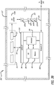
- FIG. 3A a block diagram of an intelligent hard drive 201 is illustrated that may be instantiated as the plurality of intelligent hard drives 201AA-201XY in the high speed intelligent network recorder (HSINR) 200,170,170'.
- HINR high speed intelligent network recorder
- the intelligent hard drive 201 includes a microcomputer 210 coupled to a hard drive storage device 212, a magnetic hard disk drive.
- the magnetic hard disk drive 212 includes a magnetic disk drive controller 313A and one or more read/write heads 315 coupled together.
- the magnetic hard disk drive 212 further includes one or more magnetic platters 317 that are rotated by an electric motor 318.
- the one or more read/write heads 315 are pivoted together over the one or more magnetic platters 317 by an electric motor 319.
- US Patent No. 6,895,500 issued on May 17, 2005 to Michael S. Rothberg discloses further exemplary information regarding a magnetic hard drive and is incorporated herein by reference.
- the mechanical motions of the magnetic disks and the read/write heads of a magnetic hard disk drive can cause the drive 212 to vibrate.
- the vibrations can be significant such that it may be desirable to dampen the vibrations to reduce the stress on the socket 211 (e.g. SATA socket) of the PCB and plug (e.g. SATA connector) of the hard drive as well as other components.
- Each intelligent hard drive 201,201' in the array may further include an elastic bumper 312 around a portion of the magnetic hard disk drive 212 to dampen vibrations from the one or more rotating magnetic platters and/or the one or more moveable read/write heads.
- each elastic bumper forms an array of elastic bumpers around the array of magnetic hard disk drives.
- the micro-computer 210 of the intelligent hard drive 201 includes a processor 301, a memory 302 coupled to the processor, a network interface adapter/controller 303 coupled to the processor, a SATA interface controller 304 coupled to the processor, and a storage device 305 coupled to the processor.
- the network interface adapter/controller 303 is coupled to the high speed network switching device 202 to send and receive network flows of network data packets.
- the network interface adapter/controller 303 is coupled to the processor 301 to pass network flows of network data packets to it. Upon a query, the processor 301 may pass network flows of network data packets to the network interface adapter/controller 303.
- the network interface adapter/controller 303 may optionally be a separate device coupled to and between each processor 301 of the plurality of intelligent hard drives 201 and the high speed network switching device 202.
- FIG. 3B a block diagram of an intelligent hard drive 201' that may be instantiated as the plurality of intelligent hard drives 201AA-201XY in the high speed intelligent network recorder (HSINR) 170,170'.
- HINR high speed intelligent network recorder
- the intelligent hard drive 201' includes a microcomputer 210 coupled to a hard drive storage device 212', a solid state storage drive (SSD) 212'.
- the hard drive storage devices 212 and 212' have the same form factor so they are interchangeable.
- the solid state storage drive 212' includes a solid state drive controller 313B coupled to a plug 311 and a non-volatile memory array 357 including a plurality non-volatile memory devices 327A-327N coupled to the solid state drive controller 313B.
- the plug 311 e.g., SATA connector
- the solid state storage drive (SSD) 212' couples to the socket 211 mounted to the printed circuit board 299.
- the solid state storage drive 212' has no moving parts, there are no vibrations generated by each. Accordingly, an elastic bumper around a solid state storage drive is not needed to dampen vibrations.
- the intelligent hard drive 201" of Figure 3C includes a plurality of hard drives 212A-212F and a micro-computer 210 coupled in communication together.
- the intelligent hard drive 201" may be instantiated multiple times as the plurality of intelligent hard drives 201AA-201XY in the high speed intelligent network recorder (HSINR) 170,170'.
- HINR high speed intelligent network recorder
- Each of the plurality of hard drives 212A-212F of the intelligent hard driver may be a magnetic disk drive 212 or a solid state storage drive 212'.
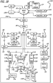
- FIG. 5 illustrates a block diagram of an instance of the high speed switch 202.
- the high speed switch 202 includes an N to N cross point switch 501, a controller 502 with a program memory 512, a plurality of network interfaces (NI) 503A-503N, 504A-504N, 505, 506, and a plurality of buffer memories 513, 514, 515, 516.
- the controller 502 is coupled to each to control the switching of packets in the switch and within the high speed intelligent network recorder (HSINR) 170,170'. Instructions stored in the program memory 512 cause the controller 502 to generate control signals and control the switch.
- HINR high speed intelligent network recorder
- the network interface 505 couples to other networking equipment in the data center computer network 100A,100B such as the intelligent load balancer 801, and/or tap 400,400' shown in Figures 1A-1B .
- the network interface 506 may couple to other networking equipment in the data center computer network 100A,100B such as the analyzers 156L shown in Figures 1A-1B .
- the N to N cross point switch 501 switches packets between the devices coupled to the network interfaces 503A-503N, 504A-504N.
- a packet such as a command packet for example, may be multicasted to network interfaces 503A-503N,504A-504N so that the plurality of intelligent hard drives 201AA-201XY in the high speed intelligent network recorder (HSINR) 170,170' may act together.
- HINR high speed intelligent network recorder
- Storage of the data packet communication into and out of a computer network can be useful in making a determination of what data was compromised, how the data was compromised, and whom performed the attack.
- stored data packet communications can become less relevant and useful over time. Accordingly, the more recent data packet communication is more desirable to store into the capacity of the array of the plurality of intelligent hard drives 201AA-201XY.
- the array of the plurality of intelligent hard drives 201AA-201XY shown in Figure 2B records a plurality of flows of network data packets, eventually filling the capacity of the aggregated plurality of the array of intelligent hard drives 201AA-201XY, without the need for data redundancy such as may be found in a redundant array of independent disks (RAID).
- the capacity of the array of intelligent hard drives 201AA-201XY defines a relevant data time window of network data packets (ingress and egress) associated with network flows.
- the network data packets stored in the array of intelligent hard drives 201AA-201XY are readily accessible for queries and analysis during the relevant data time window, which may be performed in a distributed manner by the processors or microcomputers 210. Generally, data need not be recovered by backup software before it can be used or analyzed.
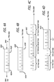
- Figures 4A-4D illustrate drawings of relevant data time windows 400A-400D for the array of intelligent hard drives 201AA-201XY along a data time axis.
- the capacity of the array of intelligent hard drives 201AA-201XY can be represented by the relevant data time windows 400A-400D along the data time axis Td.
- the network data flows that are stored into the array of intelligent hard drives 201AA-201XY, the relevant stored data, is represented by the data flows 402A-402B within the relevant data time windows 400A-400D.
- the more recent stored network data flows 402B are the youngest data packets stored into the array of intelligent hard drives represented by being nearest one end of a relevant data time window 400A.
- the earlier stored network data flows 402A are the oldest data packets stored into the array of intelligent hard drives represented by being nearest an opposite end of the relevant data time window 400A.
- relevant stored data 412 in the array of intelligent hard drives is represented by network data flows within the relevant data time window 400C.
- Past network data flows 413 that have been overwritten are shown outside the relevant data time window 400C at one end.
- Future expected network data flows 415 are shown outside the relevant data time window 400C at the opposite end.
- the capacity of the array of intelligent hard drives may change over time. Sectors within one or more hard drives may be mapped out from being written to. One or more sectors may have uncorrectable errors such that they are unreadable. One hard drive may completely fail so that its entire capacity may be unavailable and eliminated from the capacity of the array of intelligent hard drives.
- intelligent hard drives that fail within the array may not be replaced.
- advanced notice of failing sectors and hard drives may be obtained by self-monitoring, analysis and reporting technology (SMART) data for each intelligent hard drive in the array.
- SMART self-monitoring, analysis and reporting technology
- new network data flows that are to be stored in the network recorder can avoid being stored into failing sectors or failing hard drives.
- the failing sectors or failing hard drives may still be readable. In which case, older stored network data flows may be stored in the failing sectors or failing hard drives and become more and more irrelevant as time passes.
- the capacity of the array of intelligent hard drives may initially be sized to store days, weeks, or months worth of expected network data flows of data packets into and out of a computer network between devices.
- the number of intelligent hard drives in the array may number 960 for example and store two weeks worth of network data flows. If one hard drive is lost, only a portion of the two weeks of stored network data flows is lost, such as a few hours during a day. It may not be worth the maintenance costs and lost recording time to recover a few hours of lost data capacity. Accordingly, the failing or failed intelligent hard drives are not replaced, thereby lowering maintenance costs of the network recorder. If failed intelligent hard drives have reduced the capacity of the array of intelligent hard drives to an unacceptable level, a tray of hard drives may be replaced. Alternatively, the entire network recorder may be replaced.
- the hard drives that are available at a later time may be lower in costs and developed with greater density (fewer dollars per gigabyte), such that the network recorder may be larger in capacity and lower in costs when replaced.
- Figures 6A-6D and 7A-7C illustrate implementation details for an exemplary embodiment of the high speed intelligent network recorder 200 shown in Figures 2A-2C and 3B-3C .
- Figures 6A-6D and 7A-7C illustrate embodiments of a high speed intelligent network recorder 170,170', 170" with 350 storage drives 212,212' and 20 microcomputers 750 providing a drive D to microcomputer M (D to M) ratio of 35 to 2.
- the storage array 202 of storage drives 212,212' (as well as each drive tray) may be arranged into X columns and Y rows of hard drives in order to efficiently use the space and provide the appropriate drive D to microcomputer M (D to M) ratio for the high speed intelligent network recorder.
- the 350 storage drives in the intelligent storage array 202 may be arranged as 35 columns by 10 rows of storage drives 212,212' mounted perpendicular to a backplane printed circuit board (PCB).
- PCB backplane printed circuit board
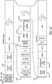
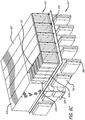
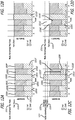
- Figure 6A illustrates a computer enclosure 614 for the high speed intelligent network recorder 170,170' viewed from the bottom.
- the computer enclosure 614 is a 6U sized metal computer enclosure.
- the metal computer enclosure 614 is utilized for mounting computing and storage resources into two bays, a top bay 615 and a bottom bay 617.
- a backplane printed circuit board (backplane PCB or backplane) 612 is mounted in the enclosure 614 between the top bay 615 and a bottom bay 617.
- the top bay 615 of the high speed intelligent network recorder receives hard drive trays 618.
- the bottom bay 617 of the high speed intelligent network recorder receives controller cards 608.
- Each side of the backplane PCB 612 includes a plurality of sockets 606.
- Sockets 606 on one side of the backplane 612 receive connectors of controller cards 608. Sockets 606 on the opposite side of the backplane PCB 612 receive connectors of hard drive trays 618 (see Figures 6C-6D ). Sockets 606 aligned with each other on opposing sides of the backplane are coupled in communication together so that controller cards 608 on one side are coupled in communication to hard drive trays 618 on the opposite side.
- the backplane PCB 612 provides power and ground to the each controller card 608 and hard drive tray 618.
- the backplane PCB 612 may further provide a communication connection to each processor of each controller card 608.
- one or more hard drive trays 618 plug into one or more sockets 606 of the backplane PCB 612 on the opposite side. When plugged in, the hard drive trays 618 are parallel with the backplane PCB 612.
- each of the one or more sockets 606 are a Com Express 2.1 connector mounted on the backplane 612.
- the controller cards 608 and the hard drive trays 618 have the same form factor and position of connectors 606 so that each may be interchangeable in the backplane 612 to provided different system configurations.
- the high speed intelligent network recorder 170,170' includes a high speed switch 202.
- the high speed switch 202 may be an integrated circuit chip mounted to the backplane printed circuit board 612.
- the high speed switch 202 may be a daughter card with a connector that plugs into a socket of the backplane printed circuit board 612.
- the high speed switch 202 may be a separate device that is mounted to the enclosure 614 or a separate device with its own 1U enclosure that is adjacent the array 220 and coupled in communication with the intelligent hard drives by wire cables or optical cables.
- the cables 282 from switch 202 couple the high speed intelligent network recorder 170,170' to the ILB or tap within the network.
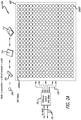
- Figure 6B illustrates the computer enclosure 614 viewed from the top.
- a drive tray 618 is plugged into the backplane PCB 612.
- a plurality of hard drives 212 are plugged into the SATA sockets 619 of the drive tray 618.
- Flows or network flows refers to bidirectional network conversations (e.g., conversation flows), identified by a flow hash tag (flow-hash) unless otherwise noted.
- the flow-hash function should be reasonably uniform, hash both directions of the same flow to the same key and a minimal collision rate.
- Broken flows refer to flows whose packet records have been sent to more than one destination node.
- a node refers to the logical unit of: a network interface or equivalent ingress construct (such as a shared memory buffer), compute, a memory and a storage device. Nodes act as endpoints for traffic from the load balancer.
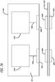
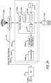
- FIG. 8A-8B and 10 a portion of the data center network is shown to describe the capture processing and intelligent load balancing of packets for the intelligent network recorder.
- FIG 8A shows an intelligent network recording system 800 including a probe (intelligent load balancing) network device 801 and a high speed intelligent network recorder coupled together.
- the intelligent network recording system 800 is coupled to the tap 400.
- the high speed intelligent network recorder (HSINR) 170, 170' includes a high speed switch 202 coupled to an intelligent storage array 220, or other suitable devices servicing as nodes of intelligent storage.
- the intelligent load balancing function of the intelligent load balancing network device 801 may be hardware implemented by one or more intelligent load balancing cards 900A-900N installed into an intelligent load balancing network device 801.
- the intelligent load balancing function provided by the ILB cards 900A-900N may be referred to as an intelligent load balancer 900.
- the intelligent load balancing network device 801 may include a query agent 2000.
- the query agent 2000 may be used to analyze the IP packets that are stored in the storage array 220 of the HSINR 170,170'.
- the intelligent load balancer 900 reads metadata (1003, 1004, 1005) from the packet record 1002, determines a destination node (e.g., a particular hard drive on an intelligent hard drive) based on the flow hash 1005 of each packet record 1002, and steers the packet record 1002 to one of N encapsulation buffers 1016 (e.g., steers packet record to buffer #0).
- Each flow hash 1005 is a uniquely calculated tag for each conversation flow.
- Each buffer may include, for example, 8 kilobytes of space.
- Each encapsulation buffer 1016 is associated with an active node (e.g., intelligent hard drive) in the intelligent network recorder 170, 170'.
- Each encapsulation buffer (buffer #0) may contain multiple packet records.
- each encapsulation buffer e.g., buffer #0
- One capture card 802 may contain multiple encapsulation buffers 1016, but encapsulation buffers 1016 are not necessarily on the capture card 802.
- the transmit stream 1018 of records is transmitted over the capture network fabric to the respective node (intelligent hard drive in the network recorder) to which they are addressed.
- the system then uses a new buffer, or reuses a buffer, for the node that received the packet 1000.
- the node address (destination address) information includes an identifier to identify the specific virtual node at the compute unit to which the record is addressed.
- the intelligent load balancer 900 assumes nodes are independent, but the intelligent load balancer 900 may take into account link bandwidth and locality when making load balancing decisions to ensure reliability and increase query performance. Note that the intelligent load balancer 900 can also be applied in a non-Ethernet situation, such as a virtual environment where the capture stream and encapsulation buffers are pipes directly connected to analysis applications.
- the intelligent load balancer 900 receives status messages 1030 from the nodes that are associated with a status update.
- a status message 1030 from a node informs the intelligent load balancer 900 of the node's capabilities, availability, and other changed events.
- the status messages 1030 may be stored into a node status and discovery buffer 1032 for continual use by the intelligent load balancer 900 to make informed load balancing decisions of the packet records to the nodes.
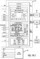
- Figure 11 illustrates details of the methods of intelligent load balancing by the intelligent load balancer 900.
- the packet processing subsystem 1101 of Figure 11 is basically the overall processes of Figure 10 .
- the hot detection and cold balancing processes 1102 and the cold balancing processes 1103 of Figure 11 are basically the processes of the intelligent load balancer 900 of Figure 10 .
- the hot detection and balancing subsystem 1102 determines whether a packet record should be considered part of a "hot” flow (and be randomly distributed) in this subsystem or considered to be part of a "cold” flow (and remain flow coherent) and further processed by the cold balancing subsystem.
- a "hot” flow is a conversation having a bandwidth that is greater than a given threshold; while a "cold” flow is a conversation having a bandwidth that is less than or equal to the given threshold.
- the system forms a record summary that includes the record timestamp 1003, the record length 1004, and the flow hash 1005.
- the system adds that record summary of the current packet record to the record summary queue 1114.
- Each record summary may also include other flags for tracking additional statistics, such as a flag for whether the record was considered part of a hot flow and the destination that the flow was assigned to.
- the length includes record overhead as the entire record is stored at the destination.
- the record summary queue 1114 has one entry of a fixed length (e.g., fixed bytes) for each packet record 1002.
- the queue 1114 may have a fixed number of records, but that is not a requirement. Accordingly, each entry in the record summary queue 114 effectively represents a period of time.
- the time periods enable the system to monitor the relative load of the different capture streams 1010 and different nodes.
- the size of the record summary queue 1114 represents the time period over which the system can measure the bandwidth for the network flow for each conversation.
- each entry is not a fixed unit of time by default, but each entry represents the time window between the packet and the next entry. Accordingly, the record summary queue 1114 provides a window for measuring approximate bandwidth for a transmission of each conversation. Accuracy of the measurement of the bandwidth tends to increase as the size of the record summary queue 1114 increases.
- the record length is inserted into a count-min sketch 1112 (or other space efficient table).
- a family of pairwise independent hash functions is used to generate the hashes for the sketch table, using the original record flow hash as the key.
- the flow hash may be provided to the load balancer, and if not, the flow hash may be computed by the load balancer.
- the count-min sketch 1112 is similar in concept to a counting bloom filter.
- the count-min sketch 1112 provides an accurate value estimate of entries above a threshold.
- the count-min sketch 1112 is known to have a low probability of false positive and is not proportional to the size of the input.
- the simplest count-min sketch 1112 variant includes a group of several pair-wise independent universal hashes which map to the same number of rows d of width w in a table. The value is inserted into each row of the table at the position computed by the hash function for that row. The value is estimated as the minimum of the values at the hash position of each row.
- Other variants exist and may be used to trade off computational complexity, accuracy and the introduction of false negatives.
- the intelligent load balancer may use the Count-Mean-Min variant of sketch that uses the mean of the row, excluding the current counter, as a noise estimate and returns the median of the counters as an unbiased estimate, finally returning the minimum of this and the minimum to reduce overestimation.
- the record length 1004 of the oldest record summary in the record summary queue 1114 is decremented (e.g., removed) from the counters in the count-min sketch 1112. Once the system decrements (e.g., removes) a record summary from the record summary queue 1114, the system forgets about that record summary.
- the count-min sketch 1112 decrement should occur before the insertion of the record summary at the record summary queue 1114. That way, the record summary does not affect the accuracy of the estimated flow queue bytes.
- the count-min sketch 1112 thereby keeps an approximate count of the number of bytes per flow hash. Accordingly, the count-min sketch 1112 is an approximate hash table or similar. The lookup (and hence counters) of the count-min sketch 1112 is approximate.
- the system can use the approximate bandwidth, the estimated byte threshold, or both, in order determine if the flow for a packet is hot (relatively high amount of traffic) or cold (relatively low amount of traffic). Once classified as hot or cold, a record is treated differently depending whether it is part of a hot flow or not.
- the system pseudo-randomly assigns the packet to the appropriate encapsulation buffer 1016 based on the load of the nodes. Accordingly, a hot flow may be spread across multiple encapsulation buffers 1016 for multiple nodes. Hot traffic generally makes up the majority of bandwidth but in a small number of flows on networks. Thus, the intelligent load balancer sends the vast majority of flows (e.g., cold flows) each to a single node, despite the low capability of the node.
- flows e.g., cold flows
- a feature of the system is a delay before a flow is detected as hot - the detection threshold is set such that at least the first N packets of the flow go to the same destination to allow deep packet inspection, such as application detection, even if the flow is later determined to be hot with its packets distributed to a plurality of nodes.
- Cold record bytes are tracked in per-node rate counters 1120 (see figures 15A-15C ), which informs the weighting of the hot balancing (see figure 14 ) and the triggering and weighting of cold balancing (see figures 15A-15C , 16 ). Additional statistics may be kept but are not strictly necessary for the operation of the system.
- the system updates the per-node cold byte rate counters 1120 by using the record length 1004 and the cold node selection.
- the counters 1120 provide an estimate of how many packets are going to a particular node. So, if a node is relatively busy, the system should not send more packets to that busy node.
- the system uses the per-node byte rate counters 1120 and the node status and discovery 1152 for cold rebalancing 1154 in the cold balancing processes 1103.
- the system is informed about the node status and discovery 1152 via the node status messages 1150.
- the node status messages 1150 can receive status messages a couple of different ways. One way is by each node periodically sending a node advertisement including static information (e.g., node exists, node is operational, node is not operational, node storage capacity, performance claim about maximum bandwidth, how full the node's receive buffer is, etc.). Another way is by each node periodically sending a node advertisement including dynamic information (e.g., the buffer is almost full, etc.).
- the load balancer 900 reassigns the buffer for that node to another encapsulation buffer 1016 for another node. If a node stops working, then the node stops sending status messages. Such a stop on advertisements informs the intelligent load balancer, via a timeout period, that the node is unavailable and cannot receive new traffic. The load balancer 900 reassigns the buffer for that inactive node to another encapsulation buffer 1016 for another node.
- the record flow hash is looked up in the cold node assignment lookup table 1156.
- the cold node assignment lookup table 1156 is updated infrequently by the cold rebalancing 1154.
- the flow hash 1005 is passed through a function (such as modulus) which uniformly maps the space of the flow hash to a smaller set of bins, each bin being associated with a node number.
- the number of bins is at least as many as the number of active destination nodes.
- Each bin is assigned to or associated with a node.
- the lookup table 1156 assigns the packet to the appropriate encapsulation buffer 1016 when the flow is determined to be cold.
- cold flows are assigned based on dynamic coarse hash-based binning by the cold node assignment lookup table 1156, similar to the hash lookup table in U.S. Patent Application No. 14/459,748 , incorporated herein by reference. It is intended that this binning of cold flows are adjusted as little as possible to avoid breaking flows. To this end there is a further mechanism where individual bins are redistributed away from a node only when it hits a threshold close to its maximum capacity. Until this point, hot redistribution maintains an even load by reducing hot traffic sent to the node.
- cold rebalancing may also be necessary with a dynamic number of nodes and should minimize the number of bin movements to minimize flow breakage.
- the cold balancer reassigns all of the bins previously assigned to the departing node in the cold node assignment lookup table 1156. Infrequent rebalancing for more even cold load based on binning and/or node statistics is also possible. However, this is likely unnecessary given the low total bandwidth at end nodes.
- the system informs the hot balancer 1118 by using the node status and discovery 1152 and the per-node cold byte rate counters 1120. Using such information, the system tends to assign a packet of a hot flow to an encapsulation buffer 1016 that is relatively less busy.
- packet records are accumulated into one of a plurality of encapsulation buffers 1016, where the plurality is the same as the number of active destination nodes.
- the buffer e.g., buffer #0
- MTU maximum supported frame size of the Ethernet network
- the content of the buffer is sent to the destination node through encapsulation into an Ethernet frame.
- the compute units attached to the internal switch fabric each have a number of attached nodes, but this detail is largely abstracted from load balancing decisions.
- the intelligent load balancer 900 is a software process running on a network capture device.
- the network capture device includes one or more data acquisition and generation (DAG) cards with Ethernet ingress capture ports and Ethernet egress ports.
- DAG data acquisition and generation
- the ingress capture ports are used to capture the network packets flowing into and out of the local area network or data center.
- the egress ports are connected via a high-speed Ethernet switch to a plurality of nodes to store the network packets.
- the high-speed Ethernet switch and the plurality of nodes may be referred to as the internal switch fabric.
- the core algorithm is expressly designed to be efficiently implementable in both software and hardware (FPGA).
- FPGA software and hardware
- a count-min sketch is used to allow high-performance implementation in high-speed SRAM, and the multiple hashes may be computed in parallel.
- the queue may use slower DRAM. However, only the linearly accessed insertion point (which is also the removal point) needs accessing per record so it could be pre-fetched.
- Periodic rebalancing operation may be implemented in software.
- the cold-node assignment lookup table may be implemented by adjusting the hardware hash tag load balancing table described in U.S. Patent Application No. 14/459,748 (using the destination node or encapsulation buffer index as the queue index).
- aspects described as "even” may also be weighted based on differing nominal bandwidth and compute capability of individual nodes.
- the pseudo-random assignment may be deterministic instead (e.g., choose node with minimum traffic).
- different policies can be applied to hot traffic, such as not balancing the hot flow unless the node is already overloaded (e.g., exceeding maximum advertised rate 1211).
- Nodes may be dynamically discovered and managed, advertising their maximum capture rate and capacity. They may also advise the intelligent load balancer of their buffer level and notify when their buffer reaches a critical level.
- the communication between nodes and ILB can occur via a multicast node advertisement system.
- the load balancer's node status and discovery subsystem may use this information in its load balancing decisions (such as in weighting the 'even' load).
- the load balancer's node status and discovery subsystem may check a destination node's status prior to sending an encapsulated record buffer, instead sending the buffer to a different node where possible if the first node has become unavailable.
- the load balancer's node status and discovery subsystem may exclude slow or unavailable nodes from further traffic distribution as well. This minimizes packet drop due to node storage or compute failure, which is more likely when using low cost hard drives.
- multiple instances of the intelligent load balancer may be executed by the probe/tap so that even higher data rates can be achieved.
- Hash-tag load balancing may be used to pre-distribute load amongst the multiple instances of the intelligent load balancer.
- the multiple instances of the intelligent load balancer may communicate, possibly via a central node manager process or system and share state about bandwidth and load, in order to maintain the correct distribution and to ensure each node in a pool of nodes is assigned to at most one intelligent load balancer to ensure timestamp ordering at the capture end.
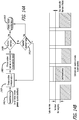
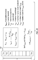
- FIG. 13 illustrates the process of cold node assignment by the cold node assignment lookup table 1156 is now described.
- the flow hash 1005 of the incoming record is passed through a mapping function f(n) that maps the packets of the flowhash consistently to a smaller number of bins (e.g., 1024 bins in Figure 13 ).
- the mapping function f(n) is a simple bit mask.
- Each bin in the cold node assignment lookup table 1156 is assigned a node.
- the cold rebalancing subsystem 1154 updates the mapping in the table 1156 when the number, or availability, of nodes changes.
- the cold rebalancing subsystem 1154 further handles cold bin movement, and may optionally perform arbitrary major rebalances for long term evenness. However, the arbitrary major rebalances should be performed infrequently by the cold rebalancing subsystem 1154 to minimize broken flows.
- the cold rebalancing subsystem 1154 would generally be in software, and the cold node assignment lookup table would be stored and updated with hardware.
- bandwidth charts are shown for a plurality of nodes to discuss traffic balancing by the intelligent load balancer 900.
- the bandwidth of the incoming stream of records for storage is divided into hot traffic and cold traffic across an arbitrary number N of nodes (six nodes A through F being depicted in the figures).
- a fair share bandwidth level 1210 and a node advertised maximum bandwidth rate level 1211 are depicted by a pair of lines in the chart with each node having the same but for Figure 12D .
- the fair share bandwidth level 1210C and the node advertised max rate level 1211C differ for node C from that of the fair share bandwidth level 1210 and the node advertised max rate level 1211 for the other nodes.
- Figure 12C illustrates a bandwidth threshold for each node by a line in the chart.
- Figure 12A illustrates a cross section of node bandwidth share (hot and cold traffic) for a plurality of nodes in a typical operation of the intelligent load balancing algorithm.
- the cold traffic may be assigned through a coarse hash-tag load balancing using the cold node assignment lookup table 1156. But for node D's cold traffic 1201D, the cold traffic 1201A-C,1201E-F is relatively well balanced amongst the nodes A-C and E-F but not exactly even. Cold traffic generally makes up a minority of the record bandwidth but the majority of flows on networks.
- the hot traffic undergoes hot traffic balancing by a hot balancer 1118.
- the hot balancer 1118 weights hot bandwidth such that each node receives an even share of the total bandwidth, referred to as a fair share 1210.
- Node D has a large exaggerated cold bandwidth share 1201D and a small hot bandwidth share 1202D but a total share that is substantially equal to the fair share bandwidth level 1210. This illustrates that random weighted hot balancing causes the percentage of hot traffic allocated to nodes to approach zero as the cold bandwidth for that node approaches the fair share amount.
- node D's cold bandwidth 1211D has exceeded the fair share 1210 of total bandwidth. In this case, node D receives no hot traffic at all. A rebalancing does not occur with the cold rebalancer 1154 at this point because it would unnecessarily break flows. However, it may be necessary to do a wider rebalancing eventually, if long term storage retention uniformity is desirable.
- the cold bandwidth assigned to node D rose beyond a threshold 1252 above the node's advertised maximum storage rate 1211.
- the cold balancer 1156 selects a single bin to reassign cold traffic to a different node, such as node E.
- the cold traffic 1223T that is to be reassigned should be reassigned to the bin (and thereby assigned to that associated node) with the most hot traffic (and thus lowest cold traffic).
- bin bandwidth statistics are not available, selecting the bin associated with the record at the time of trigger will tend towards bins with higher bandwidth.
- the cold traffic 1223T is reassigned to the node with the lowest cold flow bandwidth, in this case node E.
- the threshold 1252 could be set below or at fair share 1210 rather than above the advertised maximum rate 1211. Multiple bins could also be moved to resolve the cold traffic flow imbalance. Note that a similar number of network flows are broken when moving multiple bins individually or in a group.
- Figure 12D illustrates an example of how nodes with differing capability may be included in the weighting of the hot and cold balance algorithms, in order to distribute traffic according to node capabilities.
- node C has a lower maximum advertised storage rate 1211C than that of the higher maximum advertised storage rate 1211 for the other nodes.
- the cold bandwidth share 1231C in the cold balancing bin associated with node C is lower.
- the fair share 1210C of total bandwidth for node C is weighted lower than the fair share 1210 for the other nodes. Due to the lower fair share 1210C, the hot balancing algorithm may allocate a lower percentage of hot traffic to node C as indicated by the difference in the hot bandwidth share 1222C shown in Figure 12C and the hot bandwidth share 1232C shown in Figure 12D .
- Figures 14A illustrates a conventional process of hot balancing by using a hot balancing weighting algorithm.
- Cold byte rate counters shown in Figure 14B are used to determine the hot traffic weighting.
- the difference between current node current cold bandwidth and total bandwidth fair share is used to weight the node selection.
- the system chooses a random available node n (e.g., by using hot balancer 1118).
- the system then chooses a number m (which is random or deterministic) between 0 and a node fair share.
- the number m may be chosen once per comparison or may be chosen once per packet.
- the system determines if the number m is greater than a node cold bytes threshold. If the number m is greater, then at process 1410 the system steers the hot packet record to the node n buffer. However, if the number m is not greater than a node cold bytes threshold, then at process 1412, the system determines if the maximum number of retries has been reached for that packet record.
- the system goes to process 1410 and steers the hot packet record to the node n buffer. However, if the maximum number of retries has not been reached, then the system goes back to process 1404 and chooses another random available node n for the packet record.
- Figure 14B illustrates hot balancing by using cold byte rate counters or leaky bucket counters.
- the purpose of Figure 14B is similar to the purpose of Figure 14A .
- Figure 14A shows a "pressure based" buckets for nodes that the system "drains" at a constant rate.
- the shaded area represents the bandwidth at the nodes (e.g., nodes 1-5) for cold records.
- the system uses a bucket level in a similar way the system uses the number m for decision making in Figure 14A .
- fair share is equal to the current total bandwidth divided by the number of active nodes. Note that fair share is not a static value. The fair share value fluctuates with the current bandwidth of packets that are being stored.
- a specific algorithm flow is described but any weighted random algorithm can be used, but most require additional state. A limited number of retries is used to ensure the algorithm terminates in a timely manner, especially with unusually high cold traffic with a large number of nodes, as perfect weighting is not necessary.
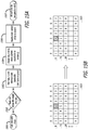
- Figures 15A and 15B describe Figure 12C in more detail.
- FIGs 15A and 15B illustrate the process of cold bin movement.
- a cold node check 1501 is triggered (such as periodically, or per cold record). Then a determination 1502 is made if the cold bandwidth of a node exceeds the node's advertised maximum capture rate (or a threshold). If the cold bandwidth of the node exceeds the threshold (yes), a bin is chosen to reassign cold traffic to another node.
- a search for a node with a minimum cold bandwidth share amongst the other available nodes is made.
- the node with the minimum cold bandwidth share is chosen to receive the reassigned cold traffic.
- the bin in the cold node assignment lookup table is rewritten by the cold balancer to be the recipient node.
- Figure 15B illustrates bin 3 being assigned from node 2 to node 4, for example. In this manner, the cold bandwidth of the overloaded node (e.g., Node 2) is reduced while breaking only one bin worth of flows.
- the overloaded node e.g., No
- a software implementation includes an extra "hot" bit 1510 in the record summary queue 1520.
- the record summary queue 1520 also includes the timestamp, the flow hash, and the record length.
- the hot bit 1510 is used to add and subtract from a per-node cold bandwidth counter (e.g., record summary queue 1114 of Figure 11 ).
- a per-node cold bandwidth counter e.g., record summary queue 1114 of Figure 11 .
- relative bandwidth can be estimated by using the queue bytes.
- absolute bandwidth can be estimated by using the queue size (e.g., queue bytes) and the queue time period.
- the system chooses the node with the lowest ratio of node cold bytes counter / (queue bytes • node max rate weight). This selection is an example of operation 1503 in Figure 15B .
- Figure 15D illustrates a leaky bucket counter that can be used for each node.
- Cold record bytes 1515 for a node are added into a bucket 1530.
- the bucket 1530 is drained of cold record bytes 1516 over time such that the level of the bucket represents node cold bandwidth (cold bandwidth of a node).
- the drain rate a fixed percentage per unit of time, is proportional to the level 1532 of cold record bytes 1517 remaining in the bucket 1530.
- Figure 16 illustrates cold bin movement rebalancing.
- Figure 16 provides additional detail for Figure 12C .
- a threshold usually just above maximum rate
- the node is sufficiently unbalanced to require a bin rebalance.
- the bin rebalance is triggered when the record that pushes the cold bandwidth over the threshold arrives, and assumes some buffering delay to limit the churn rate of very high bandwidth bins. Approximating bandwidth using a long queue also helps with this.
- Alternative methods of introducing stability such as requiring the node cold bandwidth to exceed its bandwidth for a period of time or delaying the rebalance trigger can be used.
- a bin from the overloaded node is moved by simple reassigning the bin in the cold node assignment lookup table to the node with the least bandwidth (e.g., least cold traffic).
- the system moves the bin from node 2 (overloaded node) to node 4 (node with least cold traffic).
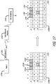
- Figure 17 pertains to moving all of the traffic off of an unavailable node
- Figure 16 above pertains to moving some traffic from an overloaded node.
- the cold balancer 1154 instead reassigns all of the bins previously assigned to the departing node (e.g., node 2) in the cold node assignment lookup table 1156 to other nodes.
- Figure 17 illustrates assigning bins 1702A-1702C associated with node 2 in table 1156A respectively to bins 1704,1706,1703 associated with nodes 4,6,3. This can be done without breaking other flows by assigning the orphaned bins to nodes with the lowest cold bandwidth, similar to the cold bin movement algorithm. A wider rebalancing over more or all nodes could also be done, if this is a rare event. However, a wider rebalancing will break more cold flows.
- the node status and discovery subsystem 1152 may be fully implemented by software executed by a processor, or implemented by a combination of software or dedicated hardware.
- the node status and discovery subsystem 1152 also maintains an active node table 1820 (e.g., pointers for nodes) and an idle node list table 1822 (e.g., first-in-first-out (FIFO) buffer for pointers).
- an active node table 1820 e.g., pointers for nodes
- an idle node list table 1822 e.g., first-in-first-out (FIFO) buffer for pointers.
- the process of Figure 18B helps determine what rebalancing can be done. If a status message 1150 indicates that an active node is becoming unavailable, an attempt is made to replace the node with an idle node from the idle node list 1822.
- the node status and discovery subsystem 1152 pops off idle nodes from the idle node list 1822 (e.g., pops off pointers) until an available idle node is found. It is preferred to use an idle node list to keep all flows from the departing node together.
- the status message 1150 causes the availability 1814 of the failing or departing node in the node status table 1820 to be updated to unavailable. Depending on the reason for unavailability and the failure history of the departing node, the departing node may be subsequently added back into the idle list 1822 for later re-use.
- the count-min sketch 1900 may be implemented with high-speed SRAM.
- the record summary queue 1902 may be implemented with slower DRAM.
- a sketch 1900 includes compact table of a plurality of counters.
- the sketch 1900 has depth d (Y-axis) with rows of width w (X-axis), such that there are (d • w) counters in the sketch.
- the size of the sketch may be related to the number of bins of flows that are to be processed by the nodes.
- each row j has a different associated pairwise-independent hash function which maps input flow hashes h( G ) (keys) onto the set of w counters Cj for that given row. Rows may be processed in parallel.
- a record with flowhash G1 is inserted into the top of the record summary queue 1902.
- the record summary queue 1902 can store N records that are shifted each time a new record is generated. With G1 being inserted into the top of the record summary queue 1902, the oldest record associated with the oldest packet(s)
- the record size S1 representing a count is added to a single counter for each row at positions h1(G1),h2(G1),...,hd(G1). Then, an estimate Estimate(G1) of the current total count for the flow hash G1 is returned as the minimum of the counters at positions h1(G1),h2(G1),...,hd(G1) within the sketch 1900.
- the estimate Estimate(G1) of the current total count for the most recent flow hash G1 is used to form an estimate of the byte threshold and the approximate bandwidth that is used to form the hot threshold 1116 and distinguish hot flows from cold flows.
- the record can be removed from the sketch 1900. For example, removal of the record with flowhash G N and record size S N is performed by subtracting the record size S N from a single counter in each row at positions h1(GN),h2(GN),...,hd(GN).
- the processor of each intelligent hard drive can quickly search through the data stored on the one or more hard drives to which it is coupled.
- a search request can be multicast out to the multicast group of intelligent hard drives so that each can search through the data stored therein.
- load balancing can be desirable in the storage of data into the array of the plurality of intelligent hard drives.
- the specific flow-coherent properties of the intelligent load balancer permit highly efficient distributed processing.
- One such distributed processing is a query process.
- Figure 20 shows a query process on the nodes in the system.
- a query agent 2000 is coupled to the intelligent network recording system 800 via the network.
- the query agent 2000 receives requests 2001 for packets from an outside or remote client.
- the requests 2001 include one or more combinations of time range, flow hash key and packet filter.
- the query agent 2000 multicasts these requests to all nodes 950.
- a node receives the multicast query 2004 from the query agent 2000, it begins the process of searching through the packets stored in its packet storage device based on timestamp and flow hash indexes. It is searching for the relevant packets to the request.
- the relevant packets that are found are passed through a query packet filter, if a query packet filter was provided with the query.
- the filtering is advantageously performed in a distributed but parallel manner at the nodes 950.
- packets are encapsulated by the node and sent back over the network 2082 to the query agent 2000 in timestamp order.
- the query agent 2000 maintains a connection with the nodes 950 that respond during the query process. Note that this is a simple multi-way merge as the nodes 950 respond in timestamp order.
- the query agent 2000 sorts them into a globally consistent timestamp order.
- the query agent 2000 then returns the packets to the requester as the response 2002.
- the packets may be returned to the requester in either a streaming manner or as a complete response capture file.
- the node During the packet storage process, the node has stored packets using indexes based on timestamp and flow hash key.
- sufficient analytic processing may be performed to determine if an arriving packet is likely to be from a broken flow.
- the presence of a "hot" indication attached to the record metadata by the intelligent load balancer confidently indicates the flow is broken.
- Additional detection heuristics for a broken flow may include, but are not limited to, protocol start and end signals and the use of full flow descriptors to check for flow hash collisions.
- a flow timeout may be used for non session-oriented flows, such as UDP.
- local query agent 2501 may use information from broken flow messages 2402 or stored in database 2012 to determine a priori which nodes contain records from the broken flow. Hot flows may be limited or excluded from flow reassembly to reduce east-west bandwidth or processed by a highly capable query agent. Broken flows residing on local node disks 212A,212B are also retrieved, although the query response embodiment may differ for efficiency reasons.
Landscapes
- Engineering & Computer Science (AREA)
- General Engineering & Computer Science (AREA)
- Theoretical Computer Science (AREA)
- Physics & Mathematics (AREA)
- Computer Hardware Design (AREA)
- Computer Security & Cryptography (AREA)
- Computer Networks & Wireless Communication (AREA)
- Signal Processing (AREA)
- General Physics & Mathematics (AREA)
- Computing Systems (AREA)
- Mathematical Physics (AREA)
- Health & Medical Sciences (AREA)
- General Health & Medical Sciences (AREA)
- Cardiology (AREA)
- Data Exchanges In Wide-Area Networks (AREA)
- Human Computer Interaction (AREA)
- Computer And Data Communications (AREA)
- Tests Of Electronic Circuits (AREA)
- Debugging And Monitoring (AREA)
- Power Sources (AREA)
- Combinations Of Printed Boards (AREA)
Claims (14)
- Procédé d'enregistrement et d'analyse d'une pluralité d'enregistrements de paquets pour des paquets de données de réseau entrant dans un réseau (100) pendant une fenêtre de temps de données (400) pertinente, ledit procédé comprenant :la réception d'une pluralité de paquets arrivants (1000) comprenant des paquets d'entrée et des paquets de sortie, chaque paquet arrivant faisant partie d'un flux d'une pluralité de flux de conversation ;la formation d'un flux de capture (1010) d'enregistrements de paquets pour les paquets arrivants, chaque enregistrement de paquets comprenant des métadonnées pourvues d'une estampille temporelle (1003), d'une longueur d'enregistrement (1004) et d'un hachage de flux (1005) ; etl'exécution d'un équilibrage de charge intelligent sur le flux de capture d'enregistrements de paquets, ledit équilibrage de charge comprenant l'extraction des métadonnées pour chaque enregistrement de paquets,la détermination si un enregistrement de paquets relève d'un flux chaud ou d'un flux froid, un flux chaud étant un flux de conversation à volume de trafic relativement élevé, et un flux froid étant un flux de conversation à volume de trafic relativement bas,la sélection d'un nœud de destination pour chaque enregistrement de paquets sur la base du hachage de flux, etle pilotage de l'enregistrement de paquets vers un tampon d'une pluralité de tampons d'encapsulation (1016) sur la base du nœud de destination, un flux froid étant dirigé de manière cohérente vers un seul nœud.
- Procédé selon la revendication 1, où :
chaque tampon d'encapsulation est prévu pour stocker temporairement une pluralité d'enregistrements de paquets pour un nœud actif particulier. - Procédé selon la revendication 1, où :
chaque hachage de flux est une étiquette calculée de manière unique pour chaque flux de conversation. - Procédé selon la revendication 1, où :
la sélection du nœud de destination pour chaque enregistrement de paquets est effectuée en réaction à la détermination que l'enregistrement de paquets relève d'un flux chaud ou d'un flux froid. - Procédé selon la revendication 1, où l'exécution d'un équilibrage de charge intelligent comprend en outre :la formation d'une pluralité de résumés d'enregistrement pour des enregistrements de paquets sur la base de l'estampille temporelle, de la longueur d'enregistrement et du hachage de flux ;l'ajout de la pluralité de résumés d'enregistrement à une file de résumés d'enregistrement ;l'application d'un croquis CM à la longueur d'enregistrement et au hachage de flux de chaque enregistrement de paquets, ledit croquis CM donnant une estimation de la longueur totale d'enregistrements représentés dans la file de résumés d'enregistrement pour un flux de conversation particulier ; etsur la base de la longueur totale d'enregistrements estimée, la détermination qu'un enregistrement de paquets relève d'un flux chaud ou d'un flux froid.
- Procédé selon la revendication 1, où l'exécution d'un équilibrage de charge intelligent comprend en outre :la formation d'une pluralité de résumés d'enregistrement pour des enregistrements de paquets sur la base de l'estampille temporelle, de la longueur d'enregistrement et du hachage de flux ;l'ajout de la pluralité de résumés d'enregistrement à une file de résumés d'enregistrement ;l'approximation d'une largeur de bande récente totale sur la base de la pluralité de résumés d'enregistrement dans la file de résumés d'enregistrement ; et,sur la base de la largeur de bande récente totale, la détermination qu'un enregistrement de paquets relève d'un flux chaud ou d'un flux froid.
- Procédé selon la revendication 1, où l'exécution d'un équilibrage de charge intelligent comprend en outre :
l'exécution d'un rééquilibrage à froid comprenant la réaffectation d'enregistrements de paquets pour un flux froid à un tampon différent de la pluralité de tampons d'encapsulation. - Procédé selon la revendication 1, où l'exécution d'un équilibrage de charge intelligent comprend en outre :la réception d'un message de statut de nœud d'au moins un nœud, ledit message de statut de nœud comprenant des informations statiques relatives au noeud ; etl'exécution d'un statut et d'une découverte de nœud au moyen des informations statiques relatives au nœud.
- Procédé selon la revendication 1, où l'exécution d'un équilibrage de charge intelligent comprend en outre :la réception d'un message de statut de nœud d'au moins un nœud, ledit message de statut de nœud comprenant des informations dynamiques relatives au noeud ; etl'exécution d'un statut et d'une découverte de nœud au moyen des informations dynamiques relatives au nœud.
- Procédé selon la revendication 1, où
une largeur de bande de capture du nœud de destination est inférieure à un dixième d'une largeur de bande entrante totale de la pluralité de flux de conversation. - Procédé selon la revendication 1, où
une largeur de bande de capture du nœud de destination est sensiblement inférieure à une largeur de bande admissible d'un seul flux chaud. - Produit lisible par ordinateur pour l'enregistrement et l'analyse d'une pluralité d'enregistrements de paquets pour des paquets de données de réseau entrant dans un réseau (100) pendant une fenêtre de temps de données (400) pertinente, ledit produit lisible par ordinateur comprenant un support de mémorisation non transitoire lisible par ordinateur stockant des instructions dont l'exécution lance les fonctions comprenant :la réception d'une pluralité de paquets arrivants (1000) comprenant des paquets d'entrée et des paquets de sortie, chaque paquet arrivant faisant partie d'un flux d'une pluralité de flux de conversation ;la formation d'un flux de capture (1010) d'enregistrements de paquets pour les paquets arrivants, chaque enregistrement de paquets comprenant des métadonnées pourvues d'une estampille temporelle (1003), d'une longueur d'enregistrement (1004) et d'un hachage de flux (1005) ; etl'exécution d'un équilibrage de charge intelligent sur le flux de capture d'enregistrements de paquets, ledit équilibrage de charge comprenant l'extraction des métadonnées pour chaque enregistrement de paquets,la détermination si un enregistrement de paquets relève d'un flux chaud ou d'un flux froid,la sélection d'un nœud de destination pour chaque enregistrement de paquets sur la base du hachage de flux, etle pilotage de l'enregistrement de paquets vers un tampon d'une pluralité de tampons d'encapsulation (1016) sur la base du nœud de destination, un flux froid étant dirigé de manière cohérente vers un seul noeud ;un flux chaud étant un flux de conversation à volume de trafic relativement élevé, et un flux froid étant un flux de conversation à volume de trafic relativement bas.
- Support lisible par ordinateur selon la revendication 12, où :
chaque tampon d'encapsulation est prévu pour stocker temporairement une pluralité d'enregistrements de paquets pour un nœud actif particulier. - Support lisible par ordinateur selon la revendication 12, où :
chaque hachage de flux est une étiquette calculée de manière unique pour chaque flux de conversation.
Applications Claiming Priority (3)
| Application Number | Priority Date | Filing Date | Title |
|---|---|---|---|
| US201562156885P | 2015-05-04 | 2015-05-04 | |
| US15/145,787 US10846257B2 (en) | 2014-04-01 | 2016-05-03 | Intelligent load balancing and high speed intelligent network recorders |
| PCT/US2016/030861 WO2016179332A1 (fr) | 2015-05-04 | 2016-05-04 | Équilibrage des charges intelligent et enregistreurs de réseau intelligents à haute vitesse |
Publications (3)
| Publication Number | Publication Date |
|---|---|
| EP3292676A1 EP3292676A1 (fr) | 2018-03-14 |
| EP3292676A4 EP3292676A4 (fr) | 2019-01-16 |
| EP3292676B1 true EP3292676B1 (fr) | 2020-02-26 |
Family
ID=57217794
Family Applications (1)
| Application Number | Title | Priority Date | Filing Date |
|---|---|---|---|
| EP16790048.9A Active EP3292676B1 (fr) | 2015-05-04 | 2016-05-04 | Équilibrage des charges intelligent et enregistreurs de réseau intelligents à haute vitesse |
Country Status (5)
| Country | Link |
|---|---|
| US (5) | US10846257B2 (fr) |
| EP (1) | EP3292676B1 (fr) |
| AU (5) | AU2016257995B2 (fr) |
| NZ (4) | NZ775606A (fr) |
| WO (1) | WO2016179332A1 (fr) |
Families Citing this family (90)
| Publication number | Priority date | Publication date | Assignee | Title |
|---|---|---|---|---|
| US8776207B2 (en) * | 2011-02-16 | 2014-07-08 | Fortinet, Inc. | Load balancing in a network with session information |
| US10454714B2 (en) | 2013-07-10 | 2019-10-22 | Nicira, Inc. | Method and system of overlay flow control |
| US10749711B2 (en) | 2013-07-10 | 2020-08-18 | Nicira, Inc. | Network-link method useful for a last-mile connectivity in an edge-gateway multipath system |
| US9680916B2 (en) * | 2013-08-01 | 2017-06-13 | Flowtraq, Inc. | Methods and systems for distribution and retrieval of network traffic records |
| US10110668B1 (en) * | 2015-03-31 | 2018-10-23 | Cisco Technology, Inc. | System and method for monitoring service nodes |
| US10498652B2 (en) | 2015-04-13 | 2019-12-03 | Nicira, Inc. | Method and system of application-aware routing with crowdsourcing |
| US10135789B2 (en) | 2015-04-13 | 2018-11-20 | Nicira, Inc. | Method and system of establishing a virtual private network in a cloud service for branch networking |
| US10425382B2 (en) | 2015-04-13 | 2019-09-24 | Nicira, Inc. | Method and system of a cloud-based multipath routing protocol |
| US9848120B2 (en) * | 2015-05-08 | 2017-12-19 | Fast Model Technology Llc | System and method for preserving video clips from a handheld device |
| US10003537B2 (en) * | 2015-10-01 | 2018-06-19 | Keysight Technologies Singapore (Holding) Pte Ltd | Egress port overload protection for network packet forwarding systems |
| WO2017214500A1 (fr) * | 2016-06-10 | 2017-12-14 | Vidscale, Inc. | Collecteur de données hiérarchiques devant être utilisé dans la collecte de données en temps réel, et techniques associées |
| US10334334B2 (en) * | 2016-07-22 | 2019-06-25 | Intel Corporation | Storage sled and techniques for a data center |
| EP3481099B1 (fr) * | 2016-08-19 | 2021-10-06 | Huawei Technologies Co., Ltd. | Procédé d'équilibrage de charge, et dispositif associé |
| US10261553B2 (en) * | 2016-08-31 | 2019-04-16 | Western Digital Technologies, Inc. | Data storage device enclosure |
| US10848432B2 (en) | 2016-12-18 | 2020-11-24 | Cisco Technology, Inc. | Switch fabric based load balancing |
| US10992568B2 (en) | 2017-01-31 | 2021-04-27 | Vmware, Inc. | High performance software-defined core network |
| US20200036624A1 (en) | 2017-01-31 | 2020-01-30 | The Mode Group | High performance software-defined core network |
| US11706127B2 (en) | 2017-01-31 | 2023-07-18 | Vmware, Inc. | High performance software-defined core network |
| US11252079B2 (en) | 2017-01-31 | 2022-02-15 | Vmware, Inc. | High performance software-defined core network |
| US20180219765A1 (en) | 2017-01-31 | 2018-08-02 | Waltz Networks | Method and Apparatus for Network Traffic Control Optimization |
| US10778528B2 (en) | 2017-02-11 | 2020-09-15 | Nicira, Inc. | Method and system of connecting to a multipath hub in a cluster |
| US10523539B2 (en) | 2017-06-22 | 2019-12-31 | Nicira, Inc. | Method and system of resiliency in cloud-delivered SD-WAN |
| US11778465B2 (en) * | 2017-06-23 | 2023-10-03 | 3M Innovative Properties Company | Wireless authentication systems |
| US10999100B2 (en) | 2017-10-02 | 2021-05-04 | Vmware, Inc. | Identifying multiple nodes in a virtual network defined over a set of public clouds to connect to an external SAAS provider |
| US10594516B2 (en) | 2017-10-02 | 2020-03-17 | Vmware, Inc. | Virtual network provider |
| US11115480B2 (en) | 2017-10-02 | 2021-09-07 | Vmware, Inc. | Layer four optimization for a virtual network defined over public cloud |
| US10965598B1 (en) | 2017-10-04 | 2021-03-30 | Cisco Technology, Inc. | Load balancing in a service chain |
| US10965596B2 (en) | 2017-10-04 | 2021-03-30 | Cisco Technology, Inc. | Hybrid services insertion |
| US11082312B2 (en) | 2017-10-04 | 2021-08-03 | Cisco Technology, Inc. | Service chaining segmentation analytics |
| CN107861565A (zh) * | 2017-10-23 | 2018-03-30 | 天津市英贝特航天科技有限公司 | 一种基于龙芯处理器的计算机控制系统 |
| US11223514B2 (en) | 2017-11-09 | 2022-01-11 | Nicira, Inc. | Method and system of a dynamic high-availability mode based on current wide area network connectivity |
| CN107979636B (zh) * | 2017-11-10 | 2020-10-16 | 上海华讯网络系统有限公司 | 冷热数据分介质存储平台设计系统及方法 |
| US10637756B2 (en) * | 2017-11-13 | 2020-04-28 | Cisco Technology, Inc. | Traffic analytics service for telemetry routers and monitoring systems |
| US10432539B2 (en) | 2017-12-13 | 2019-10-01 | Micro Focus Llc | Network traffic data summarization |
| US10756992B2 (en) | 2017-12-13 | 2020-08-25 | Micro Focus Llc | Display of network activity data |
| JP2019201342A (ja) * | 2018-05-17 | 2019-11-21 | 富士通株式会社 | 検証パケット生成装置、検証システム、および検証パケット生成プログラム |
| JP7081403B2 (ja) * | 2018-09-10 | 2022-06-07 | 富士フイルムビジネスイノベーション株式会社 | 情報処理装置及びプログラム |
| US11431829B2 (en) | 2019-03-06 | 2022-08-30 | Parsons Corporation | Multi-tiered packet processing |
| KR102898485B1 (ko) | 2019-03-21 | 2025-12-09 | 삼성전자주식회사 | 무선 통신 시스템에서 주파수 측정 방법 및 장치 |
| US11368524B1 (en) * | 2019-08-21 | 2022-06-21 | Meta Platforms, Inc. | Systems and methods for rate-based load balancing |
| US11310170B2 (en) | 2019-08-27 | 2022-04-19 | Vmware, Inc. | Configuring edge nodes outside of public clouds to use routes defined through the public clouds |
| CN110753000A (zh) * | 2019-10-21 | 2020-02-04 | 张丽媛 | 一种通信改进方法 |
| US11611507B2 (en) | 2019-10-28 | 2023-03-21 | Vmware, Inc. | Managing forwarding elements at edge nodes connected to a virtual network |
| CN110868333A (zh) * | 2019-10-28 | 2020-03-06 | 云深互联(北京)科技有限公司 | 一种用于网关的数据缓存方法及系统 |
| US11489783B2 (en) | 2019-12-12 | 2022-11-01 | Vmware, Inc. | Performing deep packet inspection in a software defined wide area network |
| US11394640B2 (en) * | 2019-12-12 | 2022-07-19 | Vmware, Inc. | Collecting and analyzing data regarding flows associated with DPI parameters |
| US20230099031A1 (en) * | 2019-12-17 | 2023-03-30 | Orionis Biosciences, Inc. | Bifunctional agents for protein recruitment and/or degradation |
| US11722925B2 (en) | 2020-01-24 | 2023-08-08 | Vmware, Inc. | Performing service class aware load balancing to distribute packets of a flow among multiple network links |
| US11245641B2 (en) | 2020-07-02 | 2022-02-08 | Vmware, Inc. | Methods and apparatus for application aware hub clustering techniques for a hyper scale SD-WAN |
| US11709710B2 (en) | 2020-07-30 | 2023-07-25 | Vmware, Inc. | Memory allocator for I/O operations |
| US11310297B2 (en) | 2020-08-25 | 2022-04-19 | Capital One Services, Llc | Computer-based systems configured to adjust data capacity in a data stream generated from multiple data producer applications and methods of use thereof |
| US11575591B2 (en) | 2020-11-17 | 2023-02-07 | Vmware, Inc. | Autonomous distributed forwarding plane traceability based anomaly detection in application traffic for hyper-scale SD-WAN |
| US11575600B2 (en) | 2020-11-24 | 2023-02-07 | Vmware, Inc. | Tunnel-less SD-WAN |
| US11929903B2 (en) | 2020-12-29 | 2024-03-12 | VMware LLC | Emulating packet flows to assess network links for SD-WAN |
| US12218845B2 (en) | 2021-01-18 | 2025-02-04 | VMware LLC | Network-aware load balancing |
| CN116783874A (zh) | 2021-01-18 | 2023-09-19 | Vm维尔股份有限公司 | 网络感知的负载平衡 |
| US11979325B2 (en) | 2021-01-28 | 2024-05-07 | VMware LLC | Dynamic SD-WAN hub cluster scaling with machine learning |
| US12368676B2 (en) | 2021-04-29 | 2025-07-22 | VMware LLC | Methods for micro-segmentation in SD-WAN for virtual networks |
| US12009987B2 (en) | 2021-05-03 | 2024-06-11 | VMware LLC | Methods to support dynamic transit paths through hub clustering across branches in SD-WAN |
| US11381499B1 (en) | 2021-05-03 | 2022-07-05 | Vmware, Inc. | Routing meshes for facilitating routing through an SD-WAN |
| US11729065B2 (en) | 2021-05-06 | 2023-08-15 | Vmware, Inc. | Methods for application defined virtual network service among multiple transport in SD-WAN |
| US12015536B2 (en) | 2021-06-18 | 2024-06-18 | VMware LLC | Method and apparatus for deploying tenant deployable elements across public clouds based on harvested performance metrics of types of resource elements in the public clouds |
| US11489720B1 (en) | 2021-06-18 | 2022-11-01 | Vmware, Inc. | Method and apparatus to evaluate resource elements and public clouds for deploying tenant deployable elements based on harvested performance metrics |
| US12250114B2 (en) | 2021-06-18 | 2025-03-11 | VMware LLC | Method and apparatus for deploying tenant deployable elements across public clouds based on harvested performance metrics of sub-types of resource elements in the public clouds |
| US12047282B2 (en) | 2021-07-22 | 2024-07-23 | VMware LLC | Methods for smart bandwidth aggregation based dynamic overlay selection among preferred exits in SD-WAN |
| US11375005B1 (en) | 2021-07-24 | 2022-06-28 | Vmware, Inc. | High availability solutions for a secure access service edge application |
| US12267364B2 (en) | 2021-07-24 | 2025-04-01 | VMware LLC | Network management services in a virtual network |
| US11943146B2 (en) | 2021-10-01 | 2024-03-26 | VMware LLC | Traffic prioritization in SD-WAN |
| US12603848B2 (en) | 2022-01-04 | 2026-04-14 | VMware LLC | Efficient mechanism for the transmission of multipath duplicate packets |
| US12184557B2 (en) | 2022-01-04 | 2024-12-31 | VMware LLC | Explicit congestion notification in a virtual environment |
| US12507120B2 (en) | 2022-01-12 | 2025-12-23 | Velocloud Networks, Llc | Heterogeneous hub clustering and application policy based automatic node selection for network of clouds |
| US12425395B2 (en) | 2022-01-15 | 2025-09-23 | VMware LLC | Method and system of securely adding an edge device operating in a public network to an SD-WAN |
| US12506678B2 (en) | 2022-01-25 | 2025-12-23 | VMware LLC | Providing DNS service in an SD-WAN |
| US11909815B2 (en) | 2022-06-06 | 2024-02-20 | VMware LLC | Routing based on geolocation costs |
| US20240022626A1 (en) | 2022-07-18 | 2024-01-18 | Vmware, Inc. | Dns-based gslb-aware sd-wan for low latency saas applications |
| US20240028378A1 (en) | 2022-07-20 | 2024-01-25 | Vmware, Inc. | Method for modifying an sd-wan using metric-based heat maps |
| US20240073743A1 (en) | 2022-08-28 | 2024-02-29 | Vmware, Inc. | Dynamic use of multiple wireless network links to connect a vehicle to an sd-wan |
| US20240126869A1 (en) * | 2022-10-17 | 2024-04-18 | Brian Keith Davidson | Human interface device firewall |
| US12425332B2 (en) | 2023-03-27 | 2025-09-23 | VMware LLC | Remediating anomalies in a self-healing network |
| US12034587B1 (en) | 2023-03-27 | 2024-07-09 | VMware LLC | Identifying and remediating anomalies in a self-healing network |
| US12057993B1 (en) | 2023-03-27 | 2024-08-06 | VMware LLC | Identifying and remediating anomalies in a self-healing network |
| US12507153B2 (en) | 2023-08-16 | 2025-12-23 | Velocloud Networks, Llc | Dynamic edge-to-edge across multiple hops in multi-regional large scale deployments with distributed gateways |
| US12507148B2 (en) | 2023-08-16 | 2025-12-23 | Velocloud Networks, Llc | Interconnecting clusters in multi-regional large scale deployments with distributed gateways |
| US12587468B2 (en) | 2023-08-16 | 2026-03-24 | Velocloud Networks, Llc | Route filtering for clusters in multi-regional large scale deployments with distributed gateways |
| US12261777B2 (en) | 2023-08-16 | 2025-03-25 | VMware LLC | Forwarding packets in multi-regional large scale deployments with distributed gateways |
| US12563438B2 (en) | 2023-08-16 | 2026-02-24 | Velocloud Networks, Llc | Distributed gateways for multi-regional large scale deployments |
| US12603827B2 (en) | 2023-08-16 | 2026-04-14 | Velocloud Networks, Llc | Asymmetric routing resolutions in multi-regional large scale deployments with distributed gateways |
| US12483968B2 (en) | 2023-08-16 | 2025-11-25 | Velocloud Networks, Llc | Distributed gateways for multi-regional large scale deployments |
| US12355655B2 (en) | 2023-08-16 | 2025-07-08 | VMware LLC | Forwarding packets in multi-regional large scale deployments with distributed gateways |
| US12432143B2 (en) | 2023-09-26 | 2025-09-30 | F5, Inc. | System and methods for selectively routing packets and devices thereof |
Family Cites Families (45)
| Publication number | Priority date | Publication date | Assignee | Title |
|---|---|---|---|---|
| US3069317A (en) | 1957-10-07 | 1962-12-18 | Upjohn Co | Terpin hydrate suspensions |
| US3880801A (en) | 1972-06-06 | 1975-04-29 | Michigan Chem Corp | Polyolefin plastic compositions containing halogenated aryl compounds as flame retardants |
| US6625161B1 (en) | 1999-12-14 | 2003-09-23 | Fujitsu Limited | Adaptive inverse multiplexing method and system |
| US7822967B2 (en) * | 2000-09-27 | 2010-10-26 | Huron Ip Llc | Apparatus, architecture, and method for integrated modular server system providing dynamically power-managed and work-load managed network devices |
| US7730077B2 (en) * | 2002-09-18 | 2010-06-01 | Netezza Corporation | Intelligent storage device controller |
| US7136638B2 (en) * | 2002-10-25 | 2006-11-14 | Nokia Corporation | Method and system for analyzing a network environment and network parameters |
| US20040093413A1 (en) * | 2002-11-06 | 2004-05-13 | Bean Timothy E. | Selecting and managing time specified segments from a large continuous capture of network data |
| US20050207098A1 (en) * | 2004-03-16 | 2005-09-22 | Malone Christopher G | Electrical equipment housings having a horizontally mounted connection plane |
| WO2005125116A1 (fr) | 2004-06-22 | 2005-12-29 | Telefonaktiebolaget Lm Ericsson (Publ) | Procede et dispositif de retroaction dans le reseau |
| JP4334419B2 (ja) | 2004-06-30 | 2009-09-30 | 富士通株式会社 | 伝送装置 |
| US7298612B2 (en) | 2005-10-25 | 2007-11-20 | Hewlett-Packard Development Company, L.P. | Server with vertical drive arrangement |
| US7804952B2 (en) | 2006-03-06 | 2010-09-28 | Alcatel Lucent | Prioritized call load balancing |
| US8254262B1 (en) * | 2006-03-31 | 2012-08-28 | Verint Americas, Inc. | Passive recording and load balancing |
| US8706914B2 (en) * | 2007-04-23 | 2014-04-22 | David D. Duchesneau | Computing infrastructure |
| DE102007022704B4 (de) | 2007-05-15 | 2010-12-09 | Siemens Ag | Verfahren zum Einrichten eines logischen Verbindungspfads in einem verbindungsorientierten paketvermittelten Kommunikationsnetzwerk |
| US8432796B2 (en) * | 2007-09-18 | 2013-04-30 | Verizon Patent And Licensing Inc. | Method, computer program product, and apparatus for providing automatic gain control via signal sampling and categorization |
| US8069317B2 (en) | 2007-10-12 | 2011-11-29 | International Business Machines Corporation | Providing and utilizing high performance block storage metadata |
| TWI350014B (en) * | 2008-02-21 | 2011-10-01 | Huga Optotech Inc | Light-emitting diode device and a fabrication method thereof |
| GB0823407D0 (en) | 2008-12-23 | 2009-01-28 | Nexan Technologies Ltd | Apparatus for storing data |
| US8713060B2 (en) | 2009-03-31 | 2014-04-29 | Amazon Technologies, Inc. | Control service for relational data management |
| US8508928B2 (en) * | 2009-09-24 | 2013-08-13 | Jabil Circuit, Inc. | Incorporation of multiple, 2.5-inch or smaller hard disk drives into a single drive carrier with a single midplane or baseboard connector |
| JP5271876B2 (ja) | 2009-11-12 | 2013-08-21 | 株式会社日立製作所 | パケット振り分け機能を有する装置及びパケット振り分け方式 |
| US8452932B2 (en) * | 2010-01-06 | 2013-05-28 | Storsimple, Inc. | System and method for efficiently creating off-site data volume back-ups |
| JPWO2012026040A1 (ja) * | 2010-08-27 | 2013-10-28 | 富士通株式会社 | 診断モジュール配信装置、診断モジュール配信方法、および診断モジュール配信プログラム |
| US8467175B2 (en) | 2011-02-07 | 2013-06-18 | Dell Products L.P. | System and method for an optimizable rack solution |
| US9203728B2 (en) | 2011-03-09 | 2015-12-01 | lxia | Metadata capture for testing TCP connections |
| US9019708B2 (en) | 2011-08-25 | 2015-04-28 | Lsi Corporation | Apparatus and systems having storage devices in a side accessible drive sled |
| US8880801B1 (en) * | 2011-09-28 | 2014-11-04 | Emc Corporation | Techniques for reliability and availability assessment of data storage configurations |
| US8929024B1 (en) * | 2012-03-26 | 2015-01-06 | Amazon Technologies, Inc. | Hard disk drive assembly with field-separable mechanical module and drive control |
| US9829935B2 (en) | 2012-04-23 | 2017-11-28 | Microsoft Technology Licensing, Llc | SAS integration with tray and midplane server architecture |
| US9191399B2 (en) * | 2012-09-11 | 2015-11-17 | The Boeing Company | Detection of infected network devices via analysis of responseless outgoing network traffic |
| US9300579B2 (en) | 2013-02-11 | 2016-03-29 | Cisco Technology, Inc. | Packet metadata channels carrying infrastructure metadata in networks |
| US9030814B2 (en) * | 2013-06-24 | 2015-05-12 | Aic Inc. | Screwless carrying frame for data access devices |
| US9319293B2 (en) | 2013-07-31 | 2016-04-19 | Calix, Inc. | Methods and apparatuses for network flow analysis and control |
| US9680916B2 (en) | 2013-08-01 | 2017-06-13 | Flowtraq, Inc. | Methods and systems for distribution and retrieval of network traffic records |
| US9331943B2 (en) * | 2013-09-10 | 2016-05-03 | Robin Systems, Inc. | Asynchronous scheduling informed by job characteristics and anticipatory provisioning of data for real-time, parallel processing |
| WO2015042171A1 (fr) * | 2013-09-18 | 2015-03-26 | Jolata, Inc. | Identification hautement probable de messages associés utilisant des ensembles de fonctions de hachage clairsemées |
| WO2015052171A1 (fr) | 2013-10-07 | 2015-04-16 | Saele Invest & Consulting As | Composition lipidique comestible comprenant de l'acide stéaridonique et de l'huile d'olive |
| US9231871B2 (en) * | 2013-11-25 | 2016-01-05 | Versa Networks, Inc. | Flow distribution table for packet flow load balancing |
| US20150188831A1 (en) | 2014-01-02 | 2015-07-02 | Futurewei Technologies, Inc. | System and Method for Traffic Engineering Using Link Buffer Status |
| GB2523839B (en) | 2014-03-07 | 2018-08-08 | Xyratex Tech Limited | A solid state storage carrier and a storage system |
| US10700950B2 (en) | 2014-04-15 | 2020-06-30 | Splunk Inc. | Adjusting network data storage based on event stream statistics |
| US9813528B2 (en) | 2014-07-31 | 2017-11-07 | Splunk Inc. | Priority-based processing of messages from multiple servers |
| US20160112287A1 (en) | 2014-10-16 | 2016-04-21 | WildPackets, Inc. | Storing and analyzing network traffic data |
| US9767856B2 (en) * | 2015-02-10 | 2017-09-19 | Netapp, Inc. | High density storage device system |
-
2016
- 2016-05-03 US US15/145,787 patent/US10846257B2/en active Active
- 2016-05-04 AU AU2016257995A patent/AU2016257995B2/en active Active
- 2016-05-04 EP EP16790048.9A patent/EP3292676B1/fr active Active
- 2016-05-04 NZ NZ775606A patent/NZ775606A/en unknown
- 2016-05-04 NZ NZ737993A patent/NZ737993A/en unknown
- 2016-05-04 WO PCT/US2016/030861 patent/WO2016179332A1/fr not_active Ceased
- 2016-05-04 NZ NZ775608A patent/NZ775608A/en unknown
- 2016-05-04 NZ NZ775610A patent/NZ775610A/en unknown
-
2017
- 2017-08-28 US US15/688,847 patent/US11416432B2/en active Active
-
2019
- 2019-04-30 US US16/400,022 patent/US11436175B2/en active Active
- 2019-05-02 US US16/401,396 patent/US11461265B2/en active Active
-
2020
- 2020-09-02 AU AU2020227035A patent/AU2020227035A1/en not_active Abandoned
-
2022
- 2022-01-26 US US17/585,514 patent/US12197372B2/en active Active
- 2022-05-13 AU AU2022203234A patent/AU2022203234A1/en not_active Abandoned
-
2024
- 2024-02-08 AU AU2024200791A patent/AU2024200791B2/en active Active
-
2026
- 2026-02-05 AU AU2026200851A patent/AU2026200851A1/en active Pending
Non-Patent Citations (1)
| Title |
|---|
| None * |
Also Published As
| Publication number | Publication date |
|---|---|
| AU2020227035A1 (en) | 2020-09-17 |
| NZ775608A (en) | 2023-05-26 |
| AU2016257995B2 (en) | 2020-09-17 |
| US11416432B2 (en) | 2022-08-16 |
| US20220253397A1 (en) | 2022-08-11 |
| WO2016179332A1 (fr) | 2016-11-10 |
| US20160328159A1 (en) | 2016-11-10 |
| AU2024200791A1 (en) | 2024-02-29 |
| US10846257B2 (en) | 2020-11-24 |
| US12197372B2 (en) | 2025-01-14 |
| EP3292676A4 (fr) | 2019-01-16 |
| AU2026200851A1 (en) | 2026-02-26 |
| US11461265B2 (en) | 2022-10-04 |
| EP3292676A1 (fr) | 2018-03-14 |
| NZ775606A (en) | 2023-05-26 |
| US20190324936A1 (en) | 2019-10-24 |
| AU2022203234A1 (en) | 2022-06-02 |
| NZ737993A (en) | 2022-04-29 |
| US20180004435A1 (en) | 2018-01-04 |
| NZ775610A (en) | 2023-06-30 |
| AU2016257995A1 (en) | 2017-12-21 |
| US20190324935A1 (en) | 2019-10-24 |
| US11436175B2 (en) | 2022-09-06 |
| AU2024200791B2 (en) | 2025-11-06 |
Similar Documents
| Publication | Publication Date | Title |
|---|---|---|
| AU2024200791B2 (en) | Intelligent load balancing and high speed intelligent network recorders | |
| US8059532B2 (en) | Data and control plane architecture including server-side triggered flow policy mechanism | |
| US20180253256A1 (en) | Storage area network based extended i/o metrics computation for deep insight into application performance | |
| US8843613B2 (en) | Information processing system, and management method for storage monitoring server | |
| US20130010613A1 (en) | Network switch with traffic generation capability | |
| US20080239956A1 (en) | Data and Control Plane Architecture for Network Application Traffic Management Device | |
| US20180285294A1 (en) | Quality of service based handling of input/output requests method and apparatus | |
| EP3066569B1 (fr) | Configuration de mise en réseau centralisée dans des systèmes distribués | |
| US9917762B2 (en) | Microburst monitoring system | |
| Panda et al. | SmartWatch: Accurate traffic analysis and flow-state tracking for intrusion prevention using SmartNICs | |
| TW201520770A (zh) | 用於取樣網路流之量測之埠鏡射 | |
| US20200136983A1 (en) | Microburst visibility system | |
| US8499074B2 (en) | Method and apparatus for accessing files stored in a storage access network (SAN) or network attached storage (NAS) | |
| US20190386906A1 (en) | Just-in-time identification of slow drain devices in a fibre channel network | |
| US20070053349A1 (en) | Network interface accessing multiple sized memory segments | |
| Sidoretti et al. | Dida: Distributed in-network intelligent data plane for machine learning applications | |
| Maqbool et al. | Virtual TCAM for data center switches | |
| Zhang et al. | MORS: Traffic-Aware Routing based on Temporal Attributes for Model Training Clusters | |
| US20260067310A1 (en) | System and method for detection of volumetric malicious attacks on datacenter networks | |
| Wu et al. | Edison: Event-driven Distributed System of Network Measurement | |
| Yang et al. | Per-flow state management technique for high-speed networks | |
| Kapoor | A Data Center End-host Stack for Predictable Low Latency and Dynamic Network Topologies |
Legal Events
| Date | Code | Title | Description |
|---|---|---|---|
| STAA | Information on the status of an ep patent application or granted ep patent |
Free format text: STATUS: THE INTERNATIONAL PUBLICATION HAS BEEN MADE |
|
| PUAI | Public reference made under article 153(3) epc to a published international application that has entered the european phase |
Free format text: ORIGINAL CODE: 0009012 |
|
| STAA | Information on the status of an ep patent application or granted ep patent |
Free format text: STATUS: REQUEST FOR EXAMINATION WAS MADE |
|
| 17P | Request for examination filed |
Effective date: 20171204 |
|
| AK | Designated contracting states |
Kind code of ref document: A1 Designated state(s): AL AT BE BG CH CY CZ DE DK EE ES FI FR GB GR HR HU IE IS IT LI LT LU LV MC MK MT NL NO PL PT RO RS SE SI SK SM TR |
|
| AX | Request for extension of the european patent |
Extension state: BA ME |
|
| DAV | Request for validation of the european patent (deleted) | ||
| DAX | Request for extension of the european patent (deleted) | ||
| A4 | Supplementary search report drawn up and despatched |
Effective date: 20181214 |
|
| RIC1 | Information provided on ipc code assigned before grant |
Ipc: H04L 12/26 20060101AFI20181210BHEP Ipc: H04L 29/06 20060101ALI20181210BHEP |
|
| REG | Reference to a national code |
Ref country code: DE Ref legal event code: R079 Ref document number: 602016030695 Country of ref document: DE Free format text: PREVIOUS MAIN CLASS: H04L0029060000 Ipc: H04L0012260000 |
|
| GRAP | Despatch of communication of intention to grant a patent |
Free format text: ORIGINAL CODE: EPIDOSNIGR1 |
|
| STAA | Information on the status of an ep patent application or granted ep patent |
Free format text: STATUS: GRANT OF PATENT IS INTENDED |
|
| RIC1 | Information provided on ipc code assigned before grant |
Ipc: G06F 13/40 20060101ALI20190823BHEP Ipc: G06F 13/42 20060101ALI20190823BHEP Ipc: H04L 29/06 20060101ALI20190823BHEP Ipc: H04L 12/26 20060101AFI20190823BHEP |
|
| INTG | Intention to grant announced |
Effective date: 20190920 |
|
| GRAS | Grant fee paid |
Free format text: ORIGINAL CODE: EPIDOSNIGR3 |
|
| GRAA | (expected) grant |
Free format text: ORIGINAL CODE: 0009210 |
|
| STAA | Information on the status of an ep patent application or granted ep patent |
Free format text: STATUS: THE PATENT HAS BEEN GRANTED |
|
| AK | Designated contracting states |
Kind code of ref document: B1 Designated state(s): AL AT BE BG CH CY CZ DE DK EE ES FI FR GB GR HR HU IE IS IT LI LT LU LV MC MK MT NL NO PL PT RO RS SE SI SK SM TR |
|
| REG | Reference to a national code |
Ref country code: GB Ref legal event code: FG4D |
|
| REG | Reference to a national code |
Ref country code: CH Ref legal event code: EP |
|
| REG | Reference to a national code |
Ref country code: DE Ref legal event code: R096 Ref document number: 602016030695 Country of ref document: DE |
|
| REG | Reference to a national code |
Ref country code: AT Ref legal event code: REF Ref document number: 1238989 Country of ref document: AT Kind code of ref document: T Effective date: 20200315 |
|
| REG | Reference to a national code |
Ref country code: IE Ref legal event code: FG4D |
|
| PG25 | Lapsed in a contracting state [announced via postgrant information from national office to epo] |
Ref country code: NO Free format text: LAPSE BECAUSE OF FAILURE TO SUBMIT A TRANSLATION OF THE DESCRIPTION OR TO PAY THE FEE WITHIN THE PRESCRIBED TIME-LIMIT Effective date: 20200526 Ref country code: FI Free format text: LAPSE BECAUSE OF FAILURE TO SUBMIT A TRANSLATION OF THE DESCRIPTION OR TO PAY THE FEE WITHIN THE PRESCRIBED TIME-LIMIT Effective date: 20200226 Ref country code: RS Free format text: LAPSE BECAUSE OF FAILURE TO SUBMIT A TRANSLATION OF THE DESCRIPTION OR TO PAY THE FEE WITHIN THE PRESCRIBED TIME-LIMIT Effective date: 20200226 |
|
| REG | Reference to a national code |
Ref country code: NL Ref legal event code: MP Effective date: 20200226 |
|
| REG | Reference to a national code |
Ref country code: LT Ref legal event code: MG4D |
|
| PG25 | Lapsed in a contracting state [announced via postgrant information from national office to epo] |
Ref country code: GR Free format text: LAPSE BECAUSE OF FAILURE TO SUBMIT A TRANSLATION OF THE DESCRIPTION OR TO PAY THE FEE WITHIN THE PRESCRIBED TIME-LIMIT Effective date: 20200527 Ref country code: BG Free format text: LAPSE BECAUSE OF FAILURE TO SUBMIT A TRANSLATION OF THE DESCRIPTION OR TO PAY THE FEE WITHIN THE PRESCRIBED TIME-LIMIT Effective date: 20200526 Ref country code: HR Free format text: LAPSE BECAUSE OF FAILURE TO SUBMIT A TRANSLATION OF THE DESCRIPTION OR TO PAY THE FEE WITHIN THE PRESCRIBED TIME-LIMIT Effective date: 20200226 Ref country code: IS Free format text: LAPSE BECAUSE OF FAILURE TO SUBMIT A TRANSLATION OF THE DESCRIPTION OR TO PAY THE FEE WITHIN THE PRESCRIBED TIME-LIMIT Effective date: 20200626 Ref country code: LV Free format text: LAPSE BECAUSE OF FAILURE TO SUBMIT A TRANSLATION OF THE DESCRIPTION OR TO PAY THE FEE WITHIN THE PRESCRIBED TIME-LIMIT Effective date: 20200226 Ref country code: SE Free format text: LAPSE BECAUSE OF FAILURE TO SUBMIT A TRANSLATION OF THE DESCRIPTION OR TO PAY THE FEE WITHIN THE PRESCRIBED TIME-LIMIT Effective date: 20200226 |
|
| PG25 | Lapsed in a contracting state [announced via postgrant information from national office to epo] |
Ref country code: NL Free format text: LAPSE BECAUSE OF FAILURE TO SUBMIT A TRANSLATION OF THE DESCRIPTION OR TO PAY THE FEE WITHIN THE PRESCRIBED TIME-LIMIT Effective date: 20200226 |
|
| PG25 | Lapsed in a contracting state [announced via postgrant information from national office to epo] |
Ref country code: ES Free format text: LAPSE BECAUSE OF FAILURE TO SUBMIT A TRANSLATION OF THE DESCRIPTION OR TO PAY THE FEE WITHIN THE PRESCRIBED TIME-LIMIT Effective date: 20200226 Ref country code: CZ Free format text: LAPSE BECAUSE OF FAILURE TO SUBMIT A TRANSLATION OF THE DESCRIPTION OR TO PAY THE FEE WITHIN THE PRESCRIBED TIME-LIMIT Effective date: 20200226 Ref country code: RO Free format text: LAPSE BECAUSE OF FAILURE TO SUBMIT A TRANSLATION OF THE DESCRIPTION OR TO PAY THE FEE WITHIN THE PRESCRIBED TIME-LIMIT Effective date: 20200226 Ref country code: DK Free format text: LAPSE BECAUSE OF FAILURE TO SUBMIT A TRANSLATION OF THE DESCRIPTION OR TO PAY THE FEE WITHIN THE PRESCRIBED TIME-LIMIT Effective date: 20200226 Ref country code: SM Free format text: LAPSE BECAUSE OF FAILURE TO SUBMIT A TRANSLATION OF THE DESCRIPTION OR TO PAY THE FEE WITHIN THE PRESCRIBED TIME-LIMIT Effective date: 20200226 Ref country code: EE Free format text: LAPSE BECAUSE OF FAILURE TO SUBMIT A TRANSLATION OF THE DESCRIPTION OR TO PAY THE FEE WITHIN THE PRESCRIBED TIME-LIMIT Effective date: 20200226 Ref country code: LT Free format text: LAPSE BECAUSE OF FAILURE TO SUBMIT A TRANSLATION OF THE DESCRIPTION OR TO PAY THE FEE WITHIN THE PRESCRIBED TIME-LIMIT Effective date: 20200226 Ref country code: PT Free format text: LAPSE BECAUSE OF FAILURE TO SUBMIT A TRANSLATION OF THE DESCRIPTION OR TO PAY THE FEE WITHIN THE PRESCRIBED TIME-LIMIT Effective date: 20200719 Ref country code: SK Free format text: LAPSE BECAUSE OF FAILURE TO SUBMIT A TRANSLATION OF THE DESCRIPTION OR TO PAY THE FEE WITHIN THE PRESCRIBED TIME-LIMIT Effective date: 20200226 |
|
| REG | Reference to a national code |
Ref country code: AT Ref legal event code: MK05 Ref document number: 1238989 Country of ref document: AT Kind code of ref document: T Effective date: 20200226 |
|
| REG | Reference to a national code |
Ref country code: DE Ref legal event code: R097 Ref document number: 602016030695 Country of ref document: DE |
|
| PLBE | No opposition filed within time limit |
Free format text: ORIGINAL CODE: 0009261 |
|
| STAA | Information on the status of an ep patent application or granted ep patent |
Free format text: STATUS: NO OPPOSITION FILED WITHIN TIME LIMIT |
|
| PG25 | Lapsed in a contracting state [announced via postgrant information from national office to epo] |
Ref country code: IT Free format text: LAPSE BECAUSE OF FAILURE TO SUBMIT A TRANSLATION OF THE DESCRIPTION OR TO PAY THE FEE WITHIN THE PRESCRIBED TIME-LIMIT Effective date: 20200226 Ref country code: AT Free format text: LAPSE BECAUSE OF FAILURE TO SUBMIT A TRANSLATION OF THE DESCRIPTION OR TO PAY THE FEE WITHIN THE PRESCRIBED TIME-LIMIT Effective date: 20200226 Ref country code: LI Free format text: LAPSE BECAUSE OF NON-PAYMENT OF DUE FEES Effective date: 20200531 Ref country code: MC Free format text: LAPSE BECAUSE OF FAILURE TO SUBMIT A TRANSLATION OF THE DESCRIPTION OR TO PAY THE FEE WITHIN THE PRESCRIBED TIME-LIMIT Effective date: 20200226 Ref country code: CH Free format text: LAPSE BECAUSE OF NON-PAYMENT OF DUE FEES Effective date: 20200531 |
|
| 26N | No opposition filed |
Effective date: 20201127 |
|
| PG25 | Lapsed in a contracting state [announced via postgrant information from national office to epo] |
Ref country code: PL Free format text: LAPSE BECAUSE OF FAILURE TO SUBMIT A TRANSLATION OF THE DESCRIPTION OR TO PAY THE FEE WITHIN THE PRESCRIBED TIME-LIMIT Effective date: 20200226 Ref country code: SI Free format text: LAPSE BECAUSE OF FAILURE TO SUBMIT A TRANSLATION OF THE DESCRIPTION OR TO PAY THE FEE WITHIN THE PRESCRIBED TIME-LIMIT Effective date: 20200226 |
|
| REG | Reference to a national code |
Ref country code: BE Ref legal event code: MM Effective date: 20200531 |
|
| PG25 | Lapsed in a contracting state [announced via postgrant information from national office to epo] |
Ref country code: LU Free format text: LAPSE BECAUSE OF NON-PAYMENT OF DUE FEES Effective date: 20200504 |
|
| PG25 | Lapsed in a contracting state [announced via postgrant information from national office to epo] |
Ref country code: BE Free format text: LAPSE BECAUSE OF NON-PAYMENT OF DUE FEES Effective date: 20200531 |
|
| REG | Reference to a national code |
Ref country code: DE Ref legal event code: R079 Ref document number: 602016030695 Country of ref document: DE Free format text: PREVIOUS MAIN CLASS: H04L0012260000 Ipc: H04L0043000000 |
|
| PG25 | Lapsed in a contracting state [announced via postgrant information from national office to epo] |
Ref country code: TR Free format text: LAPSE BECAUSE OF FAILURE TO SUBMIT A TRANSLATION OF THE DESCRIPTION OR TO PAY THE FEE WITHIN THE PRESCRIBED TIME-LIMIT Effective date: 20200226 Ref country code: MT Free format text: LAPSE BECAUSE OF FAILURE TO SUBMIT A TRANSLATION OF THE DESCRIPTION OR TO PAY THE FEE WITHIN THE PRESCRIBED TIME-LIMIT Effective date: 20200226 Ref country code: CY Free format text: LAPSE BECAUSE OF FAILURE TO SUBMIT A TRANSLATION OF THE DESCRIPTION OR TO PAY THE FEE WITHIN THE PRESCRIBED TIME-LIMIT Effective date: 20200226 |
|
| PG25 | Lapsed in a contracting state [announced via postgrant information from national office to epo] |
Ref country code: MK Free format text: LAPSE BECAUSE OF FAILURE TO SUBMIT A TRANSLATION OF THE DESCRIPTION OR TO PAY THE FEE WITHIN THE PRESCRIBED TIME-LIMIT Effective date: 20200226 Ref country code: AL Free format text: LAPSE BECAUSE OF FAILURE TO SUBMIT A TRANSLATION OF THE DESCRIPTION OR TO PAY THE FEE WITHIN THE PRESCRIBED TIME-LIMIT Effective date: 20200226 |
|
| PGFP | Annual fee paid to national office [announced via postgrant information from national office to epo] |
Ref country code: DE Payment date: 20250530 Year of fee payment: 10 |
|
| PGFP | Annual fee paid to national office [announced via postgrant information from national office to epo] |
Ref country code: FR Payment date: 20250527 Year of fee payment: 10 |
|
| PGFP | Annual fee paid to national office [announced via postgrant information from national office to epo] |
Ref country code: IE Payment date: 20250522 Year of fee payment: 10 |
|
| PGFP | Annual fee paid to national office [announced via postgrant information from national office to epo] |
Ref country code: GB Payment date: 20260331 Year of fee payment: 11 |