EP3292794A1 - Lit pliant - Google Patents
Lit pliant Download PDFInfo
- Publication number
- EP3292794A1 EP3292794A1 EP17184247.9A EP17184247A EP3292794A1 EP 3292794 A1 EP3292794 A1 EP 3292794A1 EP 17184247 A EP17184247 A EP 17184247A EP 3292794 A1 EP3292794 A1 EP 3292794A1
- Authority
- EP
- European Patent Office
- Prior art keywords
- fixing
- rod
- supporting
- folding bed
- frame
- Prior art date
- Legal status (The legal status is an assumption and is not a legal conclusion. Google has not performed a legal analysis and makes no representation as to the accuracy of the status listed.)
- Granted
Links
Images


Classifications
-
- A—HUMAN NECESSITIES
- A47—FURNITURE; DOMESTIC ARTICLES OR APPLIANCES; COFFEE MILLS; SPICE MILLS; SUCTION CLEANERS IN GENERAL
- A47C—CHAIRS; SOFAS; BEDS
- A47C27/00—Spring, stuffed or fluid mattresses or cushions specially adapted for chairs, beds or sofas
- A47C27/08—Fluid mattresses
- A47C27/081—Fluid mattresses of pneumatic type
-
- A—HUMAN NECESSITIES
- A47—FURNITURE; DOMESTIC ARTICLES OR APPLIANCES; COFFEE MILLS; SPICE MILLS; SUCTION CLEANERS IN GENERAL
- A47C—CHAIRS; SOFAS; BEDS
- A47C17/00—Sofas; Couches; Beds
- A47C17/64—Travelling or camp beds
- A47C17/70—Travelling or camp beds the bed frame being foldable about a horizontal axis
-
- A—HUMAN NECESSITIES
- A47—FURNITURE; DOMESTIC ARTICLES OR APPLIANCES; COFFEE MILLS; SPICE MILLS; SUCTION CLEANERS IN GENERAL
- A47C—CHAIRS; SOFAS; BEDS
- A47C19/00—Bedsteads
- A47C19/12—Folding bedsteads
- A47C19/122—Folding bedsteads foldable head to foot only
Definitions
- the present invention relates to the technical field of bedding, and particularly to a folding bed.
- a folding bed is usually made by tying canvas to a wood frame or a metal frame, mostly for marching or field work. It has a small volume after being folded into a bag, and has the characteristics of being easy to carry.
- the folding beds in the prior art include a bed frame and a bed cloth. When needed, the user unfolds the bed frame, and then ties the bed cloth to the bed frame, and the human body lies on the bed cloth.
- An object of the present invention is to provide a folding bed so as to resolve the technical problem that the comfort degree of the folding beds is relatively low in the prior art.
- the folding bed provided in the present invention includes a support frame and an air mattress; the air mattress is arranged on the support frame; the support frame is used to support the air mattress.
- the support frame includes a fixing frame, a movable frame and a first fixing structure; the fixing frame is rotationally connected with the movable frame; the first fixing structure is arranged on the fixing frame and the movable frame for fixing the movable frame with the fixing frame after the movable frame is rotated relative to the fixing frame by a predetermined angle.
- the first fixing structure includes a fixing part provided with a fixing hole and a first fixing protrusion used to be snapped in the fixing hole; the first fixing protrusion is provided on the movable frame; the fixing part is provided on the fixing frame.
- the first fixing structure further includes a spring; the movable frame is provided with a groove; the first fixing protrusion has one end arranged in the groove, and the other end used to be snapped in the fixing hole; the spring has one end connected with a bottom wall of the groove, and the other end connected with the first fixing protrusion.
- the fixing part includes a first side wall and a second side wall provided in parallel at an interval; the first fixing protrusion is in number of two; the movable frame includes a movable rod; both the first side wall and the second side wall are provided with a plurality of the fixing holes; the movable rod is rotationally connected with the first side wall and the second side wall via a rotation shaft; all of the plurality of fixing holes on the first side wall and the second side wall are distributed in a circular arc shape with the rotation shaft as a circle center; the two first fixing protrusions are symmetrically arranged on both sides of the movable rod, and one of the two first fixing protrusions is used to be snapped in the fixing hole on the first side wall, and the other is used to be snapped in the fixing hole on the second side wall.
- a supporting bracket is further included; the supporting bracket is arranged on one side of the support frame away from the air mattress for supporting the support frame.
- the supporting bracket includes a connecting rod and two supporting parts; the two supporting parts are oppositely arranged on two sides of the support frame respectively; and two ends of the connecting rod are connected with one of the supporting parts respectively.
- the air mattress is detachably connected with the support frame.
- the air mattress is provided with a hook for hanging on the support frame.
- the support frame includes: a supporting body and a fixing mechanism; the fixing mechanism includes an adjusting portion and a second supporting rod; the second supporting rod is used to fix the air mattress; the adjusting portion is arranged on the supporting body; the second supporting rod is fixed on the adjusting portion; the adjusting portion is used to adjust a position of the second supporting rod and unfold the air mattress.
- the adjusting portion includes an adjusting part and a second fixing structure; the adjusting part is rotationally connected with the supporting body; the second supporting rod is fixedly connected with the adjusting part; the second fixing structure is able to have the adjusting part fixed with the supporting body after the adjusting part unfolds the air mattress.
- the adjusting part includes an adjusting plate; the adjusting plate is provided with an arc-shaped slot for the second supporting rod to snap in.
- the adjusting part includes a handle; and the handle is fixedly connected with the adjusting plate.
- the fixing mechanism is in number of two; the two fixing mechanisms are arranged at an interval on the supporting body; and the two supporting rods are used to be fixedly connected with two opposite ends of the air mattress respectively.
- the supporting body includes a U-shape rod; and the adjusting portion is connected with an upper end of the U-shape rod.
- the supporting body includes a first sub-rod, a second sub-rod and a third sub-rod; the first sub-rod, the second sub-rod and the third sub-rod are detachably fixed and connected in sequence so as to form the U-shape rod; and the adjusting portion is arranged on an upper end of the first sub-rod.
- the supporting body includes a third connector, a fourth connector and an elastic element;
- the third connector is provided with a first connecting hole and a second connecting hole;
- the fourth connector is provided with a third connecting hole and a fourth connecting hole; a lower end of the first sub-rod is inserted in the first connecting hole; both ends of the second sub-rod are respectively inserted in the second connecting hole and the third connecting hole; a lower end of the third sub-rod is inserted in the fourth connecting hole; one end of the elastic element is fixedly connected with an inner wall of the second connecting hole, and the other end passes through the second sub-rod and fixedly connected with an inner wall of the third connecting hole.
- the air mattress is made from a composite fabric consisting of TPU, PVC or EVA
- the folding bed provided in the present invention includes the support frame and the air mattress, the air mattress being arranged on the support frame, and the support frame supporting the air mattress.
- the air mattress touches the back of the human body. Since the air mattress is internally filled with air, the air mattress is relatively soft when supporting the back of the human body, thus the comfort degree of the folding bed is improved.
- orientational or positional relationships indicated by terms such as “upper”, “lower”, “inner”, and “outer” are based on orientational or positional relationships as shown in the figures, merely for facilitating describing the present invention and simplifying the description, rather than indicating or suggesting that related devices or elements have to be in the specific orientation or configured and operated in specific orientation, therefore, they should not be construed as limiting the present invention.
- terms such as “first”, “second” and “third” are merely for descriptive purpose, but should not be construed as indicating or implying relative importance.
- mount should be understood in a broad sense, for example, it can be a fixed connection, a detachable connection, or an integrated connection; it can be a mechanical connection or an electrical connection; and it can be a direct connection or an indirect connection through an intermediate medium; and also can be an inner communication between two elements.
- mount can be a fixed connection, a detachable connection, or an integrated connection; it can be a mechanical connection or an electrical connection; and it can be a direct connection or an indirect connection through an intermediate medium; and also can be an inner communication between two elements.
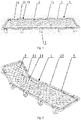
- Fig. 1 is a structural schematic diagram of a folding bed provided in a first example of the present invention.
- the folding bed provided in the present example includes: a support frame 1 and an air mattress 2; the air mattress 2 is arranged on the support frame 1; the support frame 1 is used to support the air mattress 2.
- the air mattress 2 is a cushion internally filled with air.
- the air mattress 2 also can be provided with a plurality of connecting portions. There is no air at the connecting portions so as to form recessed portions.
- the plurality of connecting portions separate the air mattress 2 into a plurality of protruded portions.
- the material of the support frame 1 can be of multiple types, for example, plastic, stainless steel and aluminum alloy.
- the material of the support frame 1 is aluminum alloy which has high intensity and light weight, so that the user can conveniently carry the support frame 1.
- the support frame 1 also can be assembled by air-filled pipes.
- the support frame 1 also can be provided with straps, and the user lifts up a fixing frame via the straps, which is convenient to exert force.
- the folding bed provided in the present example includes the support frame 1 and the air mattress 2, the air mattress 2 is arranged on the support frame 1, and the support frame 1 supports the air mattress 2.
- the air mattress 2 is in touch with the back of the human body. Since the air mattress 2 is internally filled with air, the air mattress 2 is relatively soft when supporting the back of the human body, thus the comfort degree of the folding bed is improved.
- Fig. 2 is another structural schematic diagram of the folding bed provided in the first example of the present invention
- Fig. 3 is a structural schematic diagram of the support frame 1 of the folding bed provided in the first example of the present invention.
- the support frame 1 includes a fixing frame 12, a movable frame 11 and a first fixing structure 13; the fixing frame 12 is rotationally connected with the movable frame 11; the first fixing structure 13 is arranged on the fixing frame 12 and the movable frame 11 for fixing the movable frame 11 with the fixing frame 12 after the movable frame 11 is rotated relative to the fixing frame 12 by a predetermined angle.
- the structural form of the first fixing structure 13 can be of multiple types, for example, as shown in Fig. 6 , the first fixing structure 13 includes an adjusting rod 9 and a fixing part, and the adjusting rod 9 is provided with a notch 10 for snapping with the fixing part.
- the adjusting rod 9 is arranged on the movable frame 11, and one end of the fixing part is connected with the fixing frame 12. After the user rotates the movable frame 11 by a predetermined angle, the fixing part is snapped in the notch 10, and the fixing part supports the movable frame 11 via the adjusting rod 9.
- there are a plurity of notches 10 are arranged in sequence on the adjusting rod 9 at intervals along an extending direction of the adjusting rod 9.
- the user can choose to snap fit the fixing part in one of the notches 10.
- the angle between the movable frame 11 and the horizontal plane is different, so that the movable frame 11 can be rotated by a plurality of angles.
- the first fixing structure 13 includes a hook 5 and a hook hole.
- the hook hole is provided on the fixing frame 12, and the hook 5 is provided on the movable frame 11. After the user rotates the movable frame 11 by a predetermined angle, the hook 5 will be hanged in the hook hole so as to fix the movable frame 11 with the fixing frame 12.
- Fig. 7 is another structural schematic diagram of the first fixing structure 13 of the folding bed provided in the first example of the present invention.
- the first fixing structure 13 further can include a movable tube 135 open at one end and a fixing tube 136 open at one end.
- a plurality of engagement protrusions 137 are provided in sequence at intervals along a circumferential direction of the movable tube 135; on an edge of the opening end of the fixing tube 136, a plurality of grooves 138 are provided in sequence at intervals along a circumferential direction of the fixing tube 136; each engagement protrusion 137 is engaged in one groove 138, and the movable tube 135 is detachably fixed and connected with the fixing tube 136.
- the movable tube 135 is connected with the movable frame, and the fixing tube 136 is connected with the fixing frame.
- the user separates the movable tube 135 from the fixing tube 136, and then rotates the movable tube 135 relative to the fixing tube 136 by a predetermined angle, so that the movable frame is rotated relative to the fixing frame by the predetermined angle, and then the engagement protrusions 137 on the movable tube 135 are engaged in the grooves 138 on the fixing tube 136, then the movable tube 135 is fixed with the fixing tube 136, so as to realize the rotation of the movable frame.
- a spring can be further provided, and one end of the spring abuts against an inner bottom wall of the movable tube 135, and the other end abuts against an inner bottom wall of the fixing tube 136.
- the elastic force of the spring can make it easy for the user to separate the movable tube 135 from the fixing tube 136.
- a first connector 139 can be further provided on the movable tube 135, and the movable tube 135 is connected with the movable frame via the first connector 139.
- a second connector 1310 is provided on the fixing tube 136, and the fixing tube 136 is connected with the fixing frame via the second connector 1310.
- Both the first connector 139 and the second connector 1310 are in a tubular shape, and one end of the first connector 139 is connected with the movable tube 135; one end of the second connector 1310 is connected with the fixing tube 136; both the movable frame and the fixing frame are U-shape rods, and the movable tubes 135, the fixing tubes 136, the first connectors 139 and the second connectors 1310 are in number of two, respectively. Both opening ends of the movable frame are respectively snapped in one first connector 139, and both opening ends of the fixing frame are respectively snapped in one second connector 1310.
- An adjusting handle 1311 can be further provided, one end of the adjusting handle 1311 is fixedly connected with the movable tube 135, and the other end is detachably fixed and connected with the fixing tube 136. Firstly, the user detaches and separates the adjusting handle 1311 from the fixing tube 136, then rotates the adjusting handle 1311, so that the movable tube 135 is rotated relative to the fixing tube 136 by a predetermined angle. When adjusting the angle of the movable frame, the adjusting handle 1311 can make it easy for the user to exert force on the movable frame.
- both the fixing frame 12 and the movable frame 11 are in a U shape, and the opening end of the fixing frame 12 is rotationally connected with the opening end of the movable frame 11.
- a holding portion 14 can be further provided on the movable frame 11, and the user can hold the holding portion 14 with a hand to rotate the movable frame 11 to increase the friction between the hand of the human body and the support frame 1, and making it easy for the user to exert force.
- the material of the holding portion 14 can be a rubber, so that the holding portion 14 is relatively soft, and the comfort degree is improved when the user rotates the movable frame 11.
- the support frame 1 includes the fixing frame 12 and the movable frame 11, and the movable frame can be rotated relative to the fixing frame 12.
- the user can rotate the movable frame 11 by a predetermined angle, so that the movable frame 11 and the fixing frame 12 are arranged with an angle therebetween. Then, the user sits on the fixing frame 12, with the user's back leaning on the movable frame 11, which further improves the comfort degree of the folding bed.
- Fig. 4 is an enlarged view of the first fixing structure of the folding bed provided in the first example of the present invention.
- the first fixing structure 13 includes a fixing part 132 provided with a fixing hole 133 and a first fixing protrusion 131 used to be snapped in the fixing hole 133; the first fixing protrusion 131 is provided on the movable frame 11; the fixing part 132 is provided on the fixing frame 12.
- the first fixing protrusion 131 and the fixing hole 133 can be in number of one or two, respectively.
- the first fixing protrusions 131 and the fixing holes 133 are in number of two respectively, and the two first fixing protrusions 131 are arranged at an interval along a width direction of the fixing frame 12, and optimally, the two first fixing protrusions 131 are symmetrically arranged on both sides of the fixing frame 12, thus the movable frame 11 can be supported by the two first fixing protrusions 131, so that the movable frame 11 is under balanced forces.
- the first fixing protrusion 131 is snapped in the fixing hole 133, so that the movable frame 11 is fixed with the fixing frame 12.
- the structure is simple, and it is easy for the user to operate.
- the first fixing structure 13 further includes a spring; the movable frame 11 is provided with a groove; one end of the first fixing protrusion 131 is arranged in the groove, and the other end is used to be snapped in the fixing hole 133; one end of the spring is connected with a bottom wall 1321 of the groove, and the other end is connected with the first fixing protrusion 131.
- the first fixing protrusion 131 abuts against the fixing part 132, when the first fixing protrusion 131 is rotated to the fixing hole 133, the spring presses the first fixing protrusion 131 towards the outside of the groove, so that the first fixing protrusion 131 is snapped in the fixing hole 133, at which time the movable frame 11 is fixed with the fixing frame 12.
- the user can press the first fixing protrusion 131, so that the first fixing protrusion 131 moves out from the fixing hole 133, and then the user rotates the movable frame 11.
- the spring is arranged in the groove, and the first fixing protrusion 131 is snapped in the fixing hole 133 via a compression of the spring, which facilitates the user's operation.
- the fixing part 132 includes a first side wall 1322 and a second side wall 1323 provided in parallel at an interval; the first fixing protrusions 131 is in number of two; the movable frame 11 includes a movable rod 111.
- Both the first side wall 1322 and the second side wall 1323 are provided with a plurality of fixing holes 133; the movable rod 111 is rotationally connected with the first side wall 1322 and the second side wall 1323 via a rotation shaft 134; all of the plurality of fixing holes 133 on the first side wall 1322 and the second side wall 1323 are distributed in a circular arc shape with the rotation shaft 134 as a center.
- the two first fixing protrusions 131 are symmetrically arranged on both sides of the movable rod, and one of the two first fixing protrusions 131 is used to be snapped in the fixing hole 133 on the first side wall 1322, and the other is used to be snapped in the fixing hole 133 on the second side wall 1323.
- a bottom wall 1321 further can be provided, and the first side wall 1322 and the second side wall 1323 can be perpendicularly connected with the bottom wall 1321, and also can be connected with an acute angle therebetween.
- the first side wall 1322 and the second side wall 1323 are perpendicularly connected with the bottom wall 1321, so that a gap between the first side wall 1322 and the second side wall 1323 can be reduced, further a space occupied by the fixing part 132 is reduced.
- a radian of a circular arc formed by the plurality of fixing holes 133 can be of any degree.
- this radian is of 90°, that is, this circular arc is an one-fourth circle.
- a plurality of fixing holes 133 are distributed in a circular arc shape.
- the user can choose to snap the first fixing protrusion 131 in one of the fixing holes 133, so that the movable frame 11 can be rotated by a plurality of angles, facilitating the user's use.
- the folding bed further includes a supporting bracket; the supporting bracket is arranged on the side of the support frame 1 away from the air mattress 2 for supporting the support frame 1.
- the structural form of the supporting bracket can be of multiple types, for example, as shown in Fig. 5 , the supporting bracket includes a plurality of supporting portions; the plurality of supporting portions are arranged at equal intervals along the width and length directions of the support frame 1.
- Each supporting portion includes two first supporting rods 6 arranged with an acute angle therebetween, where one end of one first supporting rod 6 is connected with one end of the other supporting rod 6, and the other ends of the two first supporting rods 6 are connected with the support frame 1.
- the supporting bracket further can include a plurality of fixing rods 7, both ends of each fixing rod 7 are respectively connected with two supporting portions, and both ends of each fixing rod 7 are respectively connected with one end of the first supporting rod 6 away from the support frame 1.
- the supporting bracket further can include a plurality of U-shape first supporting rods 8, and the plurality of U-shape first supporting rods 8 are arranged in sequence at intervals along the length direction of the support frame 1. An opening end of each U-shape first supporting rod 8 is connected with the support frame 1.
- each U-shape first supporting rod 8 is arranged to have an acute angle with the support frame 1, thus the stability of the supporting bracket can be further improved, preventing the support frame 1 from toppling over.
- the supporting bracket is arranged on the side of the support frame 1 away from the air mattress 2, and the supporting bracket is used to support the support frame 1, so that there is a distance between the air mattress 2 and the ground.
- the supporting bracket is used to support the support frame 1, so that there is a distance between the air mattress 2 and the ground.
- the supporting bracket includes a connecting rod 4 and two supporting parts 3; the two supporting parts 3 are oppositely arranged on both sides of the support frame 1; both ends of the connecting rod 4 are connected with one supporting part 3 respectively.
- the two supporting parts 3 can be arranged at an interval along the width direction of the support frame 1.
- the connecting rods 4 can be in number of more than one.
- the plurality of groups of supporting parts 3 and more than one of connecting rods 4 are arranged in sequence at intervals along the length direction of the support frame 1. Thus, the stability of the supporting bracket can be improved when supporting the support frame 1.
- the connecting rods 4 are arranged between the two supporting parts 3. After the user lies on the air mattress 2, the gravity of the user is exerted on the support frame 1, at this time, since the supporting parts 3 are located on both sides of the support frame 1, the supporting parts 3 tend to move towards a direction away from the support frame 1. However, at this time, the connecting rods 4 apply acting forces to the supporting parts 3 to get close to the support frame 1, so that the supporting parts 3 are fixed in situ, which further improves the stability of the supporting bracket.
- the air mattress 2 is detachably connected with the support frame 1.
- the user can detach the air mattress 2 from the support frame 1, so that the air mattress 2 can be used separately, further facilitating the user's use.
- the air mattress 2 is provided with a hook 5 for hanging on the support frame 2.
- the hooks 5 is in number of more than one. All of the hooks 5 are arranged in sequence at intervals along an edge of the air mattress 2.
- the air mattress 2 is made from a composite fabric consisting of TPU, PVC or EVA.
- the material of the air mattress can be TPU (thermoplastic polyurethane), PVC (polyvinyl chloride) or EVA (ethylenevinyl acetate copolymer), that is, the material of the air mattress can be a TPU composite fabric, a PVC composite fabric or an EVA composite fabric, so that the tensile property of the air mattress is relatively strong, and the service life of the air mattress 2 is prolonged.
- TPU thermoplastic polyurethane
- PVC polyvinyl chloride
- EVA ethylenevinyl acetate copolymer
- a second example of the present invention provides a folding bed, including a support frame and a mattress, the support frame being used to support this mattress. Only the structure of the support frame is illustrated in the figure. Below the structure of the support frame is explained.
- Fig. 8 is a structural schematic diagram of the support frame of the folding bed provided in the second example of the present invention
- Fig. 9 is another structural schematic diagram of the support frame of the folding bed provided in the second example of the present invention.
- the support frame includes: a supporting body 30 and a fixing mechanism 20; the fixing mechanism 20 includes an adjusting portion 21 and a second supporting rod 22; the second supporting rod 22 is used to fix the mattress; the adjusting portion 21 is arranged on the supporting body 30; the second supporting rod 22 is fixed on the adjusting portion 21; the adjusting portion 21 is used to adjust the position of the second supporting rod 22 so as to unfold the mattress.
- the support frame includes the supporting body 30 and the fixing mechanism 20, and the fixing mechanism 20 includes the adjusting portion 21 and the second supporting rod 22.
- the user fixes one end of the mattress on the second supporting rod 22, and fixes the other end on the supporting body 30, then adjusts the position of the second supporting rod 22 via the adjusting portion 21, so as to increase the interval between both ends of the mattress, and further unfold the mattress.
- the mattress is unfolded via the adjusting portion 21 and the second supporting rod 22 provided to the support frame, so as to avoid looseness of the mattress, and improve the comfort degree when people lie thereon.
- the structural form of the adjusting portion 21 can be of multiple types, for example, the adjusting portion 21 includes a slider and a supporting block, the supporting block being provided with a plurality of sliding grooves for snapping with the slider.
- the slider is snap fitted in a corresponding sliding groove by the user so as to adjust the second supporting rod 22 to a corresponding position.
- the support frame is used in cooperation with the mattress.
- the mattress can be a separate single layer of cloth, a separate single layer of mesh, an inflatable bed or an automatic inflatable sponge bed.
- this mattress is an air mattress 2.
- the air mattress 2 When the user lies on the air mattress 2, the air mattress 2 is in touch with the back of the human body. Since the air mattress 2 is internally filled with air, the air mattress 2 is relatively soft when supporting the back of the human body, thus the comfort degree of the folding bed is improved.
- the adjusting portion 21 includes an adjusting part and a second fixing structure; the adjusting part is rotationally connected with the supporting body 30; the second supporting rod 22 is fixedly connected with the adjusting part; after the adjusting part unfolds the mattress, the second fixing structure can fix the adjusting part with the supporting body 30.
- the adjusting part is rotated relative to the supporting body 30 to adjust the position of the second supporting rod 22, so that the mattress is unfolded, at this time, the adjusting part is fixed with the supporting body 30 via the second fixing structure, to prevent the adjusting part from rotating reversely, and ensure the stability of the support frame.
- the shape of the adjusting part can be of multiple types, for example, a square shape, a circular shape, and an irregular shape.
- the structural form of the second fixing structure can be of multiple type, for example, the second fixing structure includes a second fixing protrusion 25 and a fixing groove; the second fixing protrusion 25 is arranged on the adjusting part; the fixing groove is arranged on the supporting body 30.
- the second fixing protrusion 25 is snapped in the fixing groove, so as to fix the adjusting part with the supporting body 30.
- Fig. 10 is a structural schematic diagram showing that the adjusting portion of the support frame shown in Fig. 8 is in a first position
- Fig. 11 is a structural schematic diagram showing that the adjusting portion of the support frame shown in Fig. 8 is in a second position
- Fig. 12 is a structural schematic diagram showing that the adjusting portion of the support frame shown in Fig. 8 is in a third position.
- the adjusting part includes an adjusting plate 211; the adjusting plate 211 is provided with an arc-shaped slot 23 for snapping with the second supporting rod 22.
- the user snaps the second supporting rod 22 in the arc-shaped slot 23, the adjusting plate 211 is rotated, and thereby driving the second supporting rod 22 to move, so as to adjust the position of the second supporting rod 22, the structure is simple, facilitating the installation of the second supporting rod 22.
- the arc-shaped slot 23 has a shape of semi-circular.
- the adjusting part includes a handle 24; the handle 24 is fixedly connected with the adjusting plate 211.
- the user holds the handle 24 with a hand, and then rotates the adjusting plate 211 to adjust the position of the second supporting rod 22.
- the provision of the handle 24 makes it convenient for the user to exert force.
- the fixing mechanisms 20 is in number of two; the two fixing mechanisms 20 are arranged at an interval on the supporting body 30; the two supporting rods 22 are used to be fixedly connected with two opposite ends of the mattress respectively.
- each adjusting portion 21 is fixed with one second supporting rod 22, and the user can enable the two supporting rods 22 to move towards directions away from each other via the two adjusting portions 21, that is, increase the interval between the two second supporting rods 22, so as to unfold the mattress.
- the adjusting portion 21 includes the adjusting plate 211 and the handle 24, the two supporting rods 22 are respectively snapped in one arc-shaped slot 23, the user fixes both ends of the mattress on one second supporting rod 22, then rotates the adjusting plate 211 in turn, so that the second supporting rod 22 is moved towards a direction away from the other second supporting rod 22, thus increasing the distance between the two supporting rods 22, and unfolding the mattress.
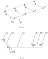
- Fig. 13 is another structural schematic diagram of the support frame of the folding bed provided in the second example of the present invention.
- the supporting bodies 30 can be in number of more than one, all of the supporting bodies 30 are arranged in sequence at intervals along the length direction of the second supporting rod 22, both ends of each supporting body 30 are connected with one fixing portion, where one second supporting rod 22 is fixed on a plurality of adjusting portions 21 on one side of the supporting body 30, and the other second supporting rod 22 is fixed on a plurality of adjusting portions 21 on the other side of the supporting body 30.
- the supporting body 30 includes a U-shape rod 31; the adjusting portion 21 is connected with an upper end of the U-shape rod 31.
- the supporting body 30 is provided as the U-shape rod 31, which is of a simple structure and subjected to force stably, and makes it easy to be moved by the user.
- the U-shape rods 31 is in number of two, the two U-shape rods 31 are arranged in parallel, and the two U-shape rods 31 are fixedly connected. Furthermore, the supporting body 30 further includes two fixing parts, both ends of the two U-shape rods 31 are respectively fixed together via one fixing part.
- the adjusting plate 211 is hinged with the fixing part.
- the fixing groove is arranged on the fixing part.
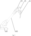
- the supporting body 30 includes a first sub-rod 110, a second sub-rod 112 and a third sub-rod 113, the first sub-rod 110, the second sub-rod 112 and the third sub-rod 113 are detachably fixed and connected in sequence so as to form the U-shape rod 31; the adjusting portion 21 is arranged on an upper end of the first sub-rod 110.
- the first sub-rod 110, the second sub-rod 112 and the third sub-rod 113 are detachably fixed and connected in sequence so as to form the U-shape rod 31. After the user completes the use, the first sub-rod 110, the second sub-rod 112 and the third sub-rod 113 can be detached and placed, which reduces the volume of the support frame and facilitates the user's transportation.
- Fig. 14 is a third structural schematic diagram of the support frame of the folding bed provided in the second example of the present invention.
- the supporting body 30 includes a third connector 114, a fourth connector 115 and an elastic element 32;
- the third connector 114 is provided with a first connecting hole and a second connecting hole;
- the fourth connector 115 is provided with a third connecting hole and a fourth connecting hole;
- a lower end of the first sub-rod 110 is snapped in the first connecting hole; both ends of the second sub-rod 112 are respectively inserted in the second connecting hole and the third connecting hole;
- a lower end of the third sub-rod 113 is snapped in the fourth connecting hole;
- the elastic element 32 has one end fixedly connected with an inner wall of the second connecting hole, and the other end passing through the second sub-rod 112 and fixedly connected with an inner wall of the third connecting hole.
- the user after completing the use, moves the second sub-rod 112 out from the second connecting hole and the third connecting hole. Due to the elastic force of the elastic element 32, the first sub-rod 110, the second sub-rod 112 and the third sub-rod 113 can be tightly pressed together, realizing the folding of the U-shape rod 31. With the provision of the elastic element 32, the first sub-rod 110, the second sub-rod 112 and the third sub-rod 113 can be still fixed together after being detached, making it convenient for the user to move and store the U-shape rod 31.
- the elastic element 32 can be an elastic rope and so on.
- the air mattress 2 is fixedly connected with the second supporting rod 22.
- the principle of the support frame is the same as the above, and unnecessary details will not be given herein.
- the folding bed provided in the examples of the present invention includes the support frame and the air mattress, the air mattress being arranged on the support frame, and the support frame supporting the air mattress.
- the air mattress touches the back of the human body. Since the air mattress is internally filled with air, the air mattress is relatively soft when supporting the back of the human body, thus the comfort degree of the folding bed is improved.
Landscapes
- Health & Medical Sciences (AREA)
- General Health & Medical Sciences (AREA)
- Nursing (AREA)
- Mattresses And Other Support Structures For Chairs And Beds (AREA)
Applications Claiming Priority (2)
| Application Number | Priority Date | Filing Date | Title |
|---|---|---|---|
| CN201610813198.4A CN106213877A (zh) | 2016-09-09 | 2016-09-09 | 多功能行军床 |
| CN201710398927.9A CN107028409A (zh) | 2017-05-31 | 2017-05-31 | 行军床架及行军床 |
Publications (2)
| Publication Number | Publication Date |
|---|---|
| EP3292794A1 true EP3292794A1 (fr) | 2018-03-14 |
| EP3292794B1 EP3292794B1 (fr) | 2019-05-15 |
Family
ID=59856335
Family Applications (1)
| Application Number | Title | Priority Date | Filing Date |
|---|---|---|---|
| EP17184247.9A Active EP3292794B1 (fr) | 2016-09-09 | 2017-08-01 | Lit pliant |
Country Status (2)
| Country | Link |
|---|---|
| US (1) | US10888172B2 (fr) |
| EP (1) | EP3292794B1 (fr) |
Cited By (1)
| Publication number | Priority date | Publication date | Assignee | Title |
|---|---|---|---|---|
| CN111839075A (zh) * | 2019-04-30 | 2020-10-30 | 深圳市云和床垫有限公司 | 垫体结构 |
Families Citing this family (9)
| Publication number | Priority date | Publication date | Assignee | Title |
|---|---|---|---|---|
| USD846915S1 (en) * | 2017-06-28 | 2019-04-30 | Quzhou Hua'ao Outdoor Products Co., Ltd | Air mattress |
| CN108577339B (zh) * | 2018-04-24 | 2025-01-17 | 湖北玥研科技有限公司 | 共享折叠床 |
| CN210748300U (zh) * | 2019-11-04 | 2020-06-16 | 金兴方 | 一种组装简便的折叠床 |
| CN111870014B (zh) * | 2020-07-20 | 2022-05-13 | 安徽省乐悠悠户外用品有限公司 | 一种户外运动用的可拆装、可折叠吊床支架 |
| GB2598767A (en) * | 2020-09-11 | 2022-03-16 | Tentbox Ltd | A camping mattress and a roof tent comprising a camping mattress |
| CN112107440B (zh) * | 2020-11-03 | 2021-08-20 | 佳木斯大学 | 一种医疗护理床的床垫限位装置 |
| CN112716195A (zh) * | 2021-01-20 | 2021-04-30 | 宁波华宇户外用品有限公司 | 休闲床的床布绷紧机构及休闲床 |
| USD1076528S1 (en) * | 2022-07-01 | 2025-05-27 | Ninghai Innovation Travel Articles Co., Ltd. | Camp bed |
| CN115153257B (zh) * | 2022-08-04 | 2023-07-25 | 慕思健康睡眠股份有限公司 | 一种床垫的智能控制方法及相关产品 |
Citations (3)
| Publication number | Priority date | Publication date | Assignee | Title |
|---|---|---|---|---|
| DE2027671A1 (de) * | 1970-06-05 | 1972-04-20 | Kurz Gmbh, 7120 Bietigheim | Gepolsterte Unterlage |
| US4594743A (en) * | 1984-07-10 | 1986-06-17 | Siesta Corp. | Air support bed |
| GB2239592A (en) * | 1989-12-20 | 1991-07-10 | Alan Silverstein | Removable-adjustable legged chair |
Family Cites Families (20)
| Publication number | Priority date | Publication date | Assignee | Title |
|---|---|---|---|---|
| FR750628A (fr) * | 1933-02-13 | 1933-08-14 | Lit de camp | |
| CH263612A (it) * | 1946-11-18 | 1949-09-15 | Vendramin Rosa | Branda scomponibile, facilmente trasportabile sotto forma di bagaglio a mano. |
| US3045257A (en) * | 1959-01-12 | 1962-07-24 | Knapp Monarch Co | Folding cot |
| GB1511227A (en) * | 1975-05-09 | 1978-05-17 | May W | Beds |
| US3967330A (en) * | 1975-05-21 | 1976-07-06 | Lawrence Peska Associates, Inc. | Folding bed |
| US4894877A (en) * | 1988-09-15 | 1990-01-23 | Marsh William C | Mobile lounge |
| CN2115705U (zh) | 1992-01-18 | 1992-09-16 | 王宗福 | 多用旅行床 |
| US5598593A (en) * | 1995-02-10 | 1997-02-04 | Aqua-Leisure Industries, Inc. | Inflatable air bed |
| CN2295395Y (zh) | 1997-04-30 | 1998-10-28 | 封加钊 | 多功能折迭式睡床 |
| USD407575S (en) * | 1997-08-11 | 1999-04-06 | Meoli Jr Rudy B | Collapsible cot |
| CN2446880Y (zh) | 2000-09-21 | 2001-09-12 | 厦门进雄企业有限公司 | 一种带有气垫的轻便折叠床 |
| US7537187B2 (en) * | 2005-11-03 | 2009-05-26 | Frederick K. Park | Collapsible frame structures |
| CN201219708Y (zh) | 2008-06-03 | 2009-04-15 | 厦门革新金属制造有限公司 | 气垫床架配合结构 |
| CN202874606U (zh) | 2012-09-19 | 2013-04-17 | 浙江泰普森休闲用品有限公司 | 角度调节器和折叠床 |
| KR101381295B1 (ko) * | 2012-11-01 | 2014-04-04 | 라제건 | 간이 침대 |
| CN203969837U (zh) | 2014-06-18 | 2014-12-03 | 广州亚帝实业有限公司 | 躺床 |
| US10034551B2 (en) * | 2014-09-22 | 2018-07-31 | L&P Property Management Company | Foldable bedding foundation having L-shaped spacers |
| CN204683098U (zh) | 2015-04-07 | 2015-10-07 | 张勇 | 一种床头可调的折叠床 |
| CN205125648U (zh) | 2015-11-19 | 2016-04-06 | 刘廷聪 | 可折叠式多功能床桌椅 |
| CN205728855U (zh) * | 2016-04-15 | 2016-11-30 | 客贝利(厦门)休闲用品有限公司 | 一种折叠铁架床 |
-
2017
- 2017-06-20 US US15/627,794 patent/US10888172B2/en active Active
- 2017-08-01 EP EP17184247.9A patent/EP3292794B1/fr active Active
Patent Citations (3)
| Publication number | Priority date | Publication date | Assignee | Title |
|---|---|---|---|---|
| DE2027671A1 (de) * | 1970-06-05 | 1972-04-20 | Kurz Gmbh, 7120 Bietigheim | Gepolsterte Unterlage |
| US4594743A (en) * | 1984-07-10 | 1986-06-17 | Siesta Corp. | Air support bed |
| GB2239592A (en) * | 1989-12-20 | 1991-07-10 | Alan Silverstein | Removable-adjustable legged chair |
Cited By (2)
| Publication number | Priority date | Publication date | Assignee | Title |
|---|---|---|---|---|
| CN111839075A (zh) * | 2019-04-30 | 2020-10-30 | 深圳市云和床垫有限公司 | 垫体结构 |
| CN111839075B (zh) * | 2019-04-30 | 2022-12-06 | 深圳市云和床垫有限公司 | 垫体结构 |
Also Published As
| Publication number | Publication date |
|---|---|
| US10888172B2 (en) | 2021-01-12 |
| EP3292794B1 (fr) | 2019-05-15 |
| US20180070735A1 (en) | 2018-03-15 |
Similar Documents
| Publication | Publication Date | Title |
|---|---|---|
| US10888172B2 (en) | Folding bed | |
| CN106714619B (zh) | 折叠椅子 | |
| KR101227644B1 (ko) | 두루마리형 플렉서블 디스플레이 장치 | |
| US7996935B1 (en) | Credible and light foldable hanging bed | |
| US9375095B2 (en) | Reversible child holding accessory | |
| US12302858B2 (en) | Bath rack | |
| JP2017508547A (ja) | 硬さが調節可能なベッド等のマットレス構造 | |
| US10330247B2 (en) | Frame structure, and structure | |
| US9850681B2 (en) | Portable bed apparatus and method of use | |
| US10012007B2 (en) | Tent frame and tent with slidably coupled top poles | |
| KR20130028453A (ko) | 유압식펌프를 구비한 두루마리형 플렉서블 디스플레이 장치 | |
| CN215874026U (zh) | 一种折叠椅 | |
| US20140346818A1 (en) | Folding chair | |
| JP6284689B2 (ja) | ジョイントロック装置及びそのジョイントロック装置を備えるステッキチェア | |
| WO2016120512A1 (fr) | Meuble multifonctions | |
| US9408473B2 (en) | Portable sun shaded folding chair | |
| CN207784761U (zh) | 行军床架及行军床 | |
| KR101485133B1 (ko) | 휴대용 이동 탈의실 | |
| CN114947446B (zh) | 一种双姿态电动储物床架 | |
| KR200474929Y1 (ko) | 면적이 확장되는 다기능 매트리스 커버 | |
| CN106213877A (zh) | 多功能行军床 | |
| CN102525770A (zh) | 床靠架 | |
| JP4156011B2 (ja) | 簡易風呂及びその組み立て方法 | |
| CN107174028B (zh) | 一种改进型折叠椅 | |
| CN111588211B (zh) | 一种操作方便的折叠椅用折叠结构及折叠椅 |
Legal Events
| Date | Code | Title | Description |
|---|---|---|---|
| PUAI | Public reference made under article 153(3) epc to a published international application that has entered the european phase |
Free format text: ORIGINAL CODE: 0009012 |
|
| STAA | Information on the status of an ep patent application or granted ep patent |
Free format text: STATUS: THE APPLICATION HAS BEEN PUBLISHED |
|
| AK | Designated contracting states |
Kind code of ref document: A1 Designated state(s): AL AT BE BG CH CY CZ DE DK EE ES FI FR GB GR HR HU IE IS IT LI LT LU LV MC MK MT NL NO PL PT RO RS SE SI SK SM TR |
|
| AX | Request for extension of the european patent |
Extension state: BA ME |
|
| STAA | Information on the status of an ep patent application or granted ep patent |
Free format text: STATUS: REQUEST FOR EXAMINATION WAS MADE |
|
| 17P | Request for examination filed |
Effective date: 20180913 |
|
| RBV | Designated contracting states (corrected) |
Designated state(s): AL AT BE BG CH CY CZ DE DK EE ES FI FR GB GR HR HU IE IS IT LI LT LU LV MC MK MT NL NO PL PT RO RS SE SI SK SM TR |
|
| GRAP | Despatch of communication of intention to grant a patent |
Free format text: ORIGINAL CODE: EPIDOSNIGR1 |
|
| STAA | Information on the status of an ep patent application or granted ep patent |
Free format text: STATUS: GRANT OF PATENT IS INTENDED |
|
| INTG | Intention to grant announced |
Effective date: 20181213 |
|
| GRAS | Grant fee paid |
Free format text: ORIGINAL CODE: EPIDOSNIGR3 |
|
| GRAA | (expected) grant |
Free format text: ORIGINAL CODE: 0009210 |
|
| STAA | Information on the status of an ep patent application or granted ep patent |
Free format text: STATUS: THE PATENT HAS BEEN GRANTED |
|
| RAP1 | Party data changed (applicant data changed or rights of an application transferred) |
Owner name: ZHEJIANG NATURAL OUTDOOR GOODS INC. |
|
| AK | Designated contracting states |
Kind code of ref document: B1 Designated state(s): AL AT BE BG CH CY CZ DE DK EE ES FI FR GB GR HR HU IE IS IT LI LT LU LV MC MK MT NL NO PL PT RO RS SE SI SK SM TR |
|
| REG | Reference to a national code |
Ref country code: CH Ref legal event code: EP |
|
| REG | Reference to a national code |
Ref country code: IE Ref legal event code: FG4D |
|
| REG | Reference to a national code |
Ref country code: DE Ref legal event code: R096 Ref document number: 602017003874 Country of ref document: DE |
|
| REG | Reference to a national code |
Ref country code: NL Ref legal event code: MP Effective date: 20190515 |
|
| REG | Reference to a national code |
Ref country code: LT Ref legal event code: MG4D |
|
| PG25 | Lapsed in a contracting state [announced via postgrant information from national office to epo] |
Ref country code: FI Free format text: LAPSE BECAUSE OF FAILURE TO SUBMIT A TRANSLATION OF THE DESCRIPTION OR TO PAY THE FEE WITHIN THE PRESCRIBED TIME-LIMIT Effective date: 20190515 Ref country code: NO Free format text: LAPSE BECAUSE OF FAILURE TO SUBMIT A TRANSLATION OF THE DESCRIPTION OR TO PAY THE FEE WITHIN THE PRESCRIBED TIME-LIMIT Effective date: 20190815 Ref country code: LT Free format text: LAPSE BECAUSE OF FAILURE TO SUBMIT A TRANSLATION OF THE DESCRIPTION OR TO PAY THE FEE WITHIN THE PRESCRIBED TIME-LIMIT Effective date: 20190515 Ref country code: NL Free format text: LAPSE BECAUSE OF FAILURE TO SUBMIT A TRANSLATION OF THE DESCRIPTION OR TO PAY THE FEE WITHIN THE PRESCRIBED TIME-LIMIT Effective date: 20190515 Ref country code: ES Free format text: LAPSE BECAUSE OF FAILURE TO SUBMIT A TRANSLATION OF THE DESCRIPTION OR TO PAY THE FEE WITHIN THE PRESCRIBED TIME-LIMIT Effective date: 20190515 Ref country code: PT Free format text: LAPSE BECAUSE OF FAILURE TO SUBMIT A TRANSLATION OF THE DESCRIPTION OR TO PAY THE FEE WITHIN THE PRESCRIBED TIME-LIMIT Effective date: 20190915 Ref country code: HR Free format text: LAPSE BECAUSE OF FAILURE TO SUBMIT A TRANSLATION OF THE DESCRIPTION OR TO PAY THE FEE WITHIN THE PRESCRIBED TIME-LIMIT Effective date: 20190515 Ref country code: SE Free format text: LAPSE BECAUSE OF FAILURE TO SUBMIT A TRANSLATION OF THE DESCRIPTION OR TO PAY THE FEE WITHIN THE PRESCRIBED TIME-LIMIT Effective date: 20190515 Ref country code: AL Free format text: LAPSE BECAUSE OF FAILURE TO SUBMIT A TRANSLATION OF THE DESCRIPTION OR TO PAY THE FEE WITHIN THE PRESCRIBED TIME-LIMIT Effective date: 20190515 |
|
| PG25 | Lapsed in a contracting state [announced via postgrant information from national office to epo] |
Ref country code: LV Free format text: LAPSE BECAUSE OF FAILURE TO SUBMIT A TRANSLATION OF THE DESCRIPTION OR TO PAY THE FEE WITHIN THE PRESCRIBED TIME-LIMIT Effective date: 20190515 Ref country code: GR Free format text: LAPSE BECAUSE OF FAILURE TO SUBMIT A TRANSLATION OF THE DESCRIPTION OR TO PAY THE FEE WITHIN THE PRESCRIBED TIME-LIMIT Effective date: 20190816 Ref country code: RS Free format text: LAPSE BECAUSE OF FAILURE TO SUBMIT A TRANSLATION OF THE DESCRIPTION OR TO PAY THE FEE WITHIN THE PRESCRIBED TIME-LIMIT Effective date: 20190515 Ref country code: BG Free format text: LAPSE BECAUSE OF FAILURE TO SUBMIT A TRANSLATION OF THE DESCRIPTION OR TO PAY THE FEE WITHIN THE PRESCRIBED TIME-LIMIT Effective date: 20190815 |
|
| REG | Reference to a national code |
Ref country code: AT Ref legal event code: MK05 Ref document number: 1132408 Country of ref document: AT Kind code of ref document: T Effective date: 20190515 |
|
| PG25 | Lapsed in a contracting state [announced via postgrant information from national office to epo] |
Ref country code: CZ Free format text: LAPSE BECAUSE OF FAILURE TO SUBMIT A TRANSLATION OF THE DESCRIPTION OR TO PAY THE FEE WITHIN THE PRESCRIBED TIME-LIMIT Effective date: 20190515 Ref country code: SK Free format text: LAPSE BECAUSE OF FAILURE TO SUBMIT A TRANSLATION OF THE DESCRIPTION OR TO PAY THE FEE WITHIN THE PRESCRIBED TIME-LIMIT Effective date: 20190515 Ref country code: AT Free format text: LAPSE BECAUSE OF FAILURE TO SUBMIT A TRANSLATION OF THE DESCRIPTION OR TO PAY THE FEE WITHIN THE PRESCRIBED TIME-LIMIT Effective date: 20190515 Ref country code: EE Free format text: LAPSE BECAUSE OF FAILURE TO SUBMIT A TRANSLATION OF THE DESCRIPTION OR TO PAY THE FEE WITHIN THE PRESCRIBED TIME-LIMIT Effective date: 20190515 Ref country code: DK Free format text: LAPSE BECAUSE OF FAILURE TO SUBMIT A TRANSLATION OF THE DESCRIPTION OR TO PAY THE FEE WITHIN THE PRESCRIBED TIME-LIMIT Effective date: 20190515 |
|
| REG | Reference to a national code |
Ref country code: DE Ref legal event code: R097 Ref document number: 602017003874 Country of ref document: DE |
|
| PG25 | Lapsed in a contracting state [announced via postgrant information from national office to epo] |
Ref country code: SM Free format text: LAPSE BECAUSE OF FAILURE TO SUBMIT A TRANSLATION OF THE DESCRIPTION OR TO PAY THE FEE WITHIN THE PRESCRIBED TIME-LIMIT Effective date: 20190515 Ref country code: IT Free format text: LAPSE BECAUSE OF FAILURE TO SUBMIT A TRANSLATION OF THE DESCRIPTION OR TO PAY THE FEE WITHIN THE PRESCRIBED TIME-LIMIT Effective date: 20190515 |
|
| PLBE | No opposition filed within time limit |
Free format text: ORIGINAL CODE: 0009261 |
|
| STAA | Information on the status of an ep patent application or granted ep patent |
Free format text: STATUS: NO OPPOSITION FILED WITHIN TIME LIMIT |
|
| PG25 | Lapsed in a contracting state [announced via postgrant information from national office to epo] |
Ref country code: TR Free format text: LAPSE BECAUSE OF FAILURE TO SUBMIT A TRANSLATION OF THE DESCRIPTION OR TO PAY THE FEE WITHIN THE PRESCRIBED TIME-LIMIT Effective date: 20190515 |
|
| 26N | No opposition filed |
Effective date: 20200218 |
|
| PG25 | Lapsed in a contracting state [announced via postgrant information from national office to epo] |
Ref country code: PL Free format text: LAPSE BECAUSE OF FAILURE TO SUBMIT A TRANSLATION OF THE DESCRIPTION OR TO PAY THE FEE WITHIN THE PRESCRIBED TIME-LIMIT Effective date: 20190515 |
|
| PG25 | Lapsed in a contracting state [announced via postgrant information from national office to epo] |
Ref country code: MC Free format text: LAPSE BECAUSE OF FAILURE TO SUBMIT A TRANSLATION OF THE DESCRIPTION OR TO PAY THE FEE WITHIN THE PRESCRIBED TIME-LIMIT Effective date: 20190515 Ref country code: LU Free format text: LAPSE BECAUSE OF NON-PAYMENT OF DUE FEES Effective date: 20190801 Ref country code: SI Free format text: LAPSE BECAUSE OF FAILURE TO SUBMIT A TRANSLATION OF THE DESCRIPTION OR TO PAY THE FEE WITHIN THE PRESCRIBED TIME-LIMIT Effective date: 20190515 |
|
| REG | Reference to a national code |
Ref country code: BE Ref legal event code: MM Effective date: 20190831 |
|
| PG25 | Lapsed in a contracting state [announced via postgrant information from national office to epo] |
Ref country code: IE Free format text: LAPSE BECAUSE OF NON-PAYMENT OF DUE FEES Effective date: 20190801 |
|
| PG25 | Lapsed in a contracting state [announced via postgrant information from national office to epo] |
Ref country code: BE Free format text: LAPSE BECAUSE OF NON-PAYMENT OF DUE FEES Effective date: 20190831 |
|
| REG | Reference to a national code |
Ref country code: CH Ref legal event code: PL |
|
| PG25 | Lapsed in a contracting state [announced via postgrant information from national office to epo] |
Ref country code: CH Free format text: LAPSE BECAUSE OF NON-PAYMENT OF DUE FEES Effective date: 20200831 Ref country code: RO Free format text: LAPSE BECAUSE OF FAILURE TO SUBMIT A TRANSLATION OF THE DESCRIPTION OR TO PAY THE FEE WITHIN THE PRESCRIBED TIME-LIMIT Effective date: 20190515 Ref country code: LI Free format text: LAPSE BECAUSE OF NON-PAYMENT OF DUE FEES Effective date: 20200831 |
|
| PG25 | Lapsed in a contracting state [announced via postgrant information from national office to epo] |
Ref country code: CY Free format text: LAPSE BECAUSE OF FAILURE TO SUBMIT A TRANSLATION OF THE DESCRIPTION OR TO PAY THE FEE WITHIN THE PRESCRIBED TIME-LIMIT Effective date: 20190515 |
|
| PG25 | Lapsed in a contracting state [announced via postgrant information from national office to epo] |
Ref country code: IS Free format text: LAPSE BECAUSE OF FAILURE TO SUBMIT A TRANSLATION OF THE DESCRIPTION OR TO PAY THE FEE WITHIN THE PRESCRIBED TIME-LIMIT Effective date: 20190915 |
|
| PG25 | Lapsed in a contracting state [announced via postgrant information from national office to epo] |
Ref country code: HU Free format text: LAPSE BECAUSE OF FAILURE TO SUBMIT A TRANSLATION OF THE DESCRIPTION OR TO PAY THE FEE WITHIN THE PRESCRIBED TIME-LIMIT; INVALID AB INITIO Effective date: 20170801 Ref country code: MT Free format text: LAPSE BECAUSE OF FAILURE TO SUBMIT A TRANSLATION OF THE DESCRIPTION OR TO PAY THE FEE WITHIN THE PRESCRIBED TIME-LIMIT Effective date: 20190515 |
|
| GBPC | Gb: european patent ceased through non-payment of renewal fee |
Effective date: 20210801 |
|
| PG25 | Lapsed in a contracting state [announced via postgrant information from national office to epo] |
Ref country code: MK Free format text: LAPSE BECAUSE OF FAILURE TO SUBMIT A TRANSLATION OF THE DESCRIPTION OR TO PAY THE FEE WITHIN THE PRESCRIBED TIME-LIMIT Effective date: 20190515 |
|
| PG25 | Lapsed in a contracting state [announced via postgrant information from national office to epo] |
Ref country code: GB Free format text: LAPSE BECAUSE OF NON-PAYMENT OF DUE FEES Effective date: 20210801 |
|
| PGFP | Annual fee paid to national office [announced via postgrant information from national office to epo] |
Ref country code: DE Payment date: 20250819 Year of fee payment: 9 |
|
| PGFP | Annual fee paid to national office [announced via postgrant information from national office to epo] |
Ref country code: FR Payment date: 20250818 Year of fee payment: 9 |